EP2713669A1 - Mobile communication devices and methods for physical downlink control channel (PDCCH) monitoring - Google Patents
Mobile communication devices and methods for physical downlink control channel (PDCCH) monitoring Download PDFInfo
- Publication number
- EP2713669A1 EP2713669A1 EP13186132.0A EP13186132A EP2713669A1 EP 2713669 A1 EP2713669 A1 EP 2713669A1 EP 13186132 A EP13186132 A EP 13186132A EP 2713669 A1 EP2713669 A1 EP 2713669A1
- Authority
- EP
- European Patent Office
- Prior art keywords
- sps
- mobile communication
- communication device
- pdcch
- enabled
- Prior art date
- Legal status (The legal status is an assumption and is not a legal conclusion. Google has not performed a legal analysis and makes no representation as to the accuracy of the status listed.)
- Granted
Links
Images


Classifications
-
- H—ELECTRICITY
- H04—ELECTRIC COMMUNICATION TECHNIQUE
- H04W—WIRELESS COMMUNICATION NETWORKS
- H04W72/00—Local resource management
- H04W72/04—Wireless resource allocation
- H04W72/044—Wireless resource allocation based on the type of the allocated resource
- H04W72/0446—Resources in time domain, e.g. slots or frames
-
- H—ELECTRICITY
- H04—ELECTRIC COMMUNICATION TECHNIQUE
- H04W—WIRELESS COMMUNICATION NETWORKS
- H04W72/00—Local resource management
- H04W72/04—Wireless resource allocation
Definitions
- the invention generally relates to Physical Downlink Control Channel (PDCCH) monitoring, and more particularly, to PDCCH monitoring for a downlink assignment reception and an uplink grant reception when the User Equipment (UE) has a Semi-Persistent Scheduling (SPS) Cell Radio Network Temporary Identifier (C-RNTI).
- PDCCH Physical Downlink Control Channel
- SPS Semi-Persistent Scheduling
- C-RNTI Cell Radio Network Temporary Identifier
- WLAN Wireless Local Area Network
- WiFi Wireless Fidelity
- Bluetooth Bluetooth technology
- ZigBee ZigBee technology
- cellular technologies including Global System for Mobile communications (GSM) technology, General Packet Radio Service (GPRS) technology, Enhanced Data rates for Global Evolution (EDGE) technology, Wideband Code Division Multiple Access (WCDMA) technology, Code Division Multiple Access 2000 (CDMA2000) technology, Time Division-Synchronous Code Division Multiple Access (TD-SCDMA) technology, Worldwide Interoperability for Microwave Access (WiMAX) technology, Long Term Evolution (LTE) technology, Time- Division LTE (TD-LTE) technology, and LTE-Advanced technology, etc.
- GSM Global System for Mobile communications
- GPRS General Packet Radio Service
- EDGE Enhanced Data rates for Global Evolution
- WCDMA Wideband Code Division Multiple Access
- CDMA2000 Code Division Multiple Access 2000
- TD-SCDMA Time Division-Synchronous Code Division Multiple Access
- WiMAX Worldwide Interoperability for Micro
- SPS Semi-Persistent Scheduling
- DL and UL downlink
- DL and UL traffic channels are dynamically shared channels.
- the PDCCH must provide access grant information to indicate which user device(s) should decode the Physical Downlink Shared Channel (PDSCH) in each subframe and to indicate which user device(s) is(are) allowed to transmit on the Physical Uplink Shared Channel (PUSCH) in each subframe.
- PDSCH Physical Downlink Shared Channel
- PUSCH Physical Uplink Shared Channel
- every DL or UL Physical Resource Block (PRB) allocation must be granted via an access grant message on the PDCCH. This is sufficient for most bursty best-effort types of applications which generally have large packet sizes and thus typically only a few users must be scheduled in each subframe.
- PRB Physical Resource Block
- the access grant control channel overhead can be greatly reduced with SPS.
- a mobile communication device having an SPS C-RNTI comprises a wireless module and a controller module.
- the wireless module performs wireless transmission and reception to and from a cellular station.
- the controller module performs operations for communication controls, wherein the operations comprise: determining whether SPS has been enabled for DL, and instructing the wireless module to monitor a PDCCH for a DL assignment reception from the cellular station for a Transmission Time Interval (TTI), in response to the mobile communication device having the SPS C-RNTI and SPS having been enabled for DL.
- TTI Transmission Time Interval
- a method for monitoring a PDCCH by a mobile communication device having an SPS C-RNTI configured by a cellular station comprises the steps of: determining whether SPS has been enabled for DL; and monitoring the PDCCH for a DL assignment reception from the cellular station for a TTI, in response to the mobile communication device having the SPS C-RNTI and SPS having been enabled for DL.
- a mobile communication device having an SPS C-RNTI comprises a wireless module and a controller module.
- the wireless module performs wireless transmission and reception to and from a cellular station.
- the controller module performs operations for communication controls, wherein the operations comprise: determining whether SPS has been enabled for UL, and instructing the wireless module to monitor a PDCCH for an UL grant reception from the cellular station for a TTI, in response to the mobile communication device having the SPS C-RNTI and SPS having been enabled for UL.
- a method for monitoring a PDCCH by a mobile communication device having an SPS C-RNTI configured by a cellular station comprises the steps of: determining whether SPS has been enabled for UL; and monitoring the PDCCH for an UL grant reception from the cellular station for a TTI, in response to the mobile communication device having the SPS C-RNTI and SPS having been enabled for UL.
- a UE having a Semi-Persistent Scheduling Cell Radio Network Temporary Identifier (referred to herein as SPS C-RNTI for brevity) should always monitor the PDCCH for a DL assignment reception for a TTI.
- SPS C-RNTI Semi-Persistent Scheduling Cell Radio Network Temporary Identifier
- a UE having an SPS C-RNTI should always monitor the PDCCH for an UL grant reception for a TTI.
- the cellular station configures SPS with the UE for DL only.
- the PDCCH monitoring for the non-configured UL or DL may cause unnecessary power consumption.
- the invention proposes solutions for a UE to avoid unnecessary PDCCH monitoring when it is configured with an SPS C-RNTI.
- Fig. 1 is a block diagram illustrating a mobile communication environment according to an embodiment of the invention.
- the mobile communication device 10 wirelessly communicates with the service network 20 via an air interface.
- the mobile communication device 10 may be a smart phone, a panel Personal Computer (PC), a laptop computer, or any computing device supporting at least the wireless technology utilized by the service network 20.
- the service network 20 comprises a cellular access network 210 and a core network 220, wherein the cellular access network 210 is responsible for processing radio signals, terminating radio protocols, and connecting the mobile communication device 10 with the core network 220.
- the cellular access network 210 may comprise one or more cellular stations, such as base stations, Node-Bs, or evolved Node-B (eNB), depending on the wireless technology in use.
- eNB evolved Node-B
- the core network 220 is responsible for performing mobility management and network-side authentication. Although not shown, the core network 220 may further enable interfacing with external networks, such as the Public Switched Telephone Network (PSTN), which is called the Circuit Switched (CS) domain functionality, and/or interfacing with the Internet Protocol (IP) based Network, such as the Internet, which is called the Packet Switched (PS) domain functionality.
- PSTN Public Switched Telephone Network
- IP Internet Protocol
- PS Packet Switched
- the service network 20 may be an LTE network
- the cellular access network 210 may be an Evolved Universal Terrestrial Radio Access Network (E-UTRAN) which comprises at least one eNB
- the core network 220 may be an Evolved Packet Core (EPC) which includes a Home Subscriber Server (HSS), Mobility Management Entity (MME), Serving Gateway (S-GW), and Packet Data Network Gateway (PDN-GW or P-GW).
- EPC Evolved Packet Core
- HSS Home Subscriber Server
- MME Mobility Management Entity
- S-GW Serving Gateway
- PDN-GW Packet Data Network Gateway
- a different wireless technology such as the LTE-Advanced technology or any future evolution of the LTE technology family, may be utilized by the service network 20 and the mobile communication device 10, and the invention is not limited thereto.
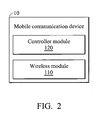
- Fig. 2 is a block diagram illustrating the mobile communication device 10 according to an embodiment of the invention.
- the mobile communication device 10 comprises a wireless module 110 and a controller module 120.
- the wireless module 110 is responsible for performing the functionality of wireless transmission and reception to and from the service network 20.
- the controller module 120 is responsible for controlling the operations of the wireless module 110 for communication controls with the service network 20, and other functional components (not shown), such as a display unit and/or keypad serving as the Man-Machine Interface (MMI), a storage unit storing the program codes of applications or communication protocols, or others.
- the controller module 120 controls the wireless module 110 for performing the method for monitoring the PDCCH when the mobile communication device 10 has an SPS C-RNTI.
- the wireless module 110 may be a Radio Frequency (RF) unit (not shown), and the controller module 120 may be a general-purpose processor or a Micro Control Unit (MCU) of a baseband unit (not shown) (which may be called a baseband processor).
- the baseband unit may contain multiple hardware devices to perform baseband signal processing, including analog to digital conversion (ADC)/digital to analog conversion (DAC), gain adjusting, modulation/demodulation, encoding/decoding, and so on.
- the RF unit may receive RF wireless signals, convert the received RF wireless signals to baseband signals, which are processed by the baseband unit, or receive baseband signals from the baseband unit and convert the received baseband signals to RF wireless signals, which are later transmitted.
- the RF unit may also contain multiple hardware devices to perform radio frequency conversion.
- the RF unit may comprise a mixer to multiply the baseband signals with a carrier oscillated in the radio frequency of the mobile communication system, wherein the radio frequency may be 900MHz, 2100MHz, or 2.6GHz utilized in LTE technology, or others depending on the wireless technology in use.
- each cellular station in the cellular access network 210 may comprise a wireless module (not shown) and a controller module (not shown), wherein the wireless module is configured to perform the functionality of wireless transceiving for the service network 120 and the controller module is configured to control the operation of the wireless module.
- Fig. 3 is a flow chart illustrating the method for monitoring the PDCCH according to an embodiment of the invention.
- the method for monitoring the PDCCH is applied to a mobile communication device having an SPS C-RNTI configured by a cellular station.
- the mobile communication device determines whether SPS has been enabled for DL (step S310), and then monitors the PDCCH for a DL assignment reception from the cellular station for a TTI, in response to the mobile communication device having the SPS C-RNTI and SPS having been enabled for DL (step S320).
- the monitoring of the PDCCH for the DL assignment reception from the cellular station may be performed for each serving cell, including Primary Cell (PCell) and Secondary Cell(s) (SCell(s)).
- PCell Primary Cell
- SCell(s) Secondary Cell
- the monitoring of the PDCCH for the DL assignment reception from the cellular station may be performed for PCell only.
- the mobile communication device of the invention checks to see if SPS has been enabled for DL before monitoring the PDCCH for a DL assignment reception, and only performs the PDCCH monitoring when SPS has been enabled for DL. That is, the mobile communication device does not monitor the PDCCH for the DL assignment reception from the cellular station for each TTI and each serving cell, in response to the mobile communication device having the SPS C-RNTI and SPS not having been enabled for DL.
- the mobile communication device of the invention advantageously avoids unnecessary PDCCH monitoring for a DL assignment reception when SPS has not been enabled for DL.
- the SPS for DL is enabled by the Radio Resource Control (RRC) layer of the communication protocol for the LTE technology, and steps S310 and S320 may be performed in compliance with the Media Access Control (MAC) layer of the communication protocol for the LTE technology.
- RRC Radio Resource Control
- MAC Media Access Control
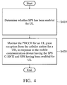
- Fig. 4 is a flow chart illustrating the method for monitoring the PDCCH according to another embodiment of the invention.
- the method for monitoring the PDCCH is applied to a mobile communication device having an SPS C-RNTI configured by a cellular station.
- the mobile communication device determines whether SPS has been enabled for UL (step S410), and then monitors the PDCCH for a UL grant reception from the cellular station for a TTI, in response to the mobile communication device having the SPS C-RNTI and SPS having been enabled for UL (step S420).
- the monitoring of the PDCCH for the UL grant reception from the cellular station may be performed for each serving cell, including Primary Cell (PCell) and Secondary Cell(s) (SCell(s)).
- PCell Primary Cell
- SCell(s) Secondary Cell
- the monitoring of the PDCCH for the UL grant reception from the cellular station may be performed for PCell only.
- the mobile communication device of the invention checks to see if SPS has been enabled for UL before monitoring the PDCCH for an UL grant reception, and only performs the PDCCH monitoring when SPS has been enabled for UL. That is, the mobile communication device does not monitor the PDCCH for the UL grant reception from the cellular station for each TTI and each serving cell, in response to the mobile communication device having the SPS C-RNTI and SPS not having been enabled for UL.
- the mobile communication device of the invention advantageously avoids unnecessary PDCCH monitoring for an UL grant reception when SPS has not been enabled for UL.
- the SPS for UL is enabled by the RRC layer of the communication protocol for the LTE technology, and steps S410 and S420 may be performed in compliance with the MAC layer of the communication protocol for the LTE technology.
Landscapes
- Engineering & Computer Science (AREA)
- Computer Networks & Wireless Communication (AREA)
- Signal Processing (AREA)
- Mobile Radio Communication Systems (AREA)
Abstract
Description
- This Application claims priority of
U.S. Application No. 14/020,457, filed on September 06, 2013 , which claims priority ofU.S. Provisional Application No. 61/707,173, filed on September 28, 2012 - The invention generally relates to Physical Downlink Control Channel (PDCCH) monitoring, and more particularly, to PDCCH monitoring for a downlink assignment reception and an uplink grant reception when the User Equipment (UE) has a Semi-Persistent Scheduling (SPS) Cell Radio Network Temporary Identifier (C-RNTI).
- With growing demand for ubiquitous computing and networking, various wireless technologies have been developed, such as the Wireless Local Area Network (WLAN) technologies, including the Wireless Fidelity (WiFi) technology, Bluetooth technology, and the ZigBee technology, etc., as well as cellular technologies including Global System for Mobile communications (GSM) technology, General Packet Radio Service (GPRS) technology, Enhanced Data rates for Global Evolution (EDGE) technology, Wideband Code Division Multiple Access (WCDMA) technology, Code Division Multiple Access 2000 (CDMA2000) technology, Time Division-Synchronous Code Division Multiple Access (TD-SCDMA) technology, Worldwide Interoperability for Microwave Access (WiMAX) technology, Long Term Evolution (LTE) technology, Time- Division LTE (TD-LTE) technology, and LTE-Advanced technology, etc.
- Taking the LTE technology as an example, a feature called Semi-Persistent Scheduling (SPS) has been proposed to reduce control channel overhead for applications that require persistent radio resource allocations such as Voice over Internet Protocol (VoIP). For the LTE technology, both downlink (DL) and uplink (UL) are fully scheduled since the DL and UL traffic channels are dynamically shared channels. This means that the PDCCH must provide access grant information to indicate which user device(s) should decode the Physical Downlink Shared Channel (PDSCH) in each subframe and to indicate which user device(s) is(are) allowed to transmit on the Physical Uplink Shared Channel (PUSCH) in each subframe. Without SPS, every DL or UL Physical Resource Block (PRB) allocation must be granted via an access grant message on the PDCCH. This is sufficient for most bursty best-effort types of applications which generally have large packet sizes and thus typically only a few users must be scheduled in each subframe. However, for applications that require persistent allocations of small packets (e.g. VoIP), the access grant control channel overhead can be greatly reduced with SPS.
- In a first aspect of the invention, a mobile communication device having an SPS C-RNTI is provided. The mobile communication device comprises a wireless module and a controller module. The wireless module performs wireless transmission and reception to and from a cellular station. The controller module performs operations for communication controls, wherein the operations comprise: determining whether SPS has been enabled for DL, and instructing the wireless module to monitor a PDCCH for a DL assignment reception from the cellular station for a Transmission Time Interval (TTI), in response to the mobile communication device having the SPS C-RNTI and SPS having been enabled for DL.
- In a second aspect of the invention, a method for monitoring a PDCCH by a mobile communication device having an SPS C-RNTI configured by a cellular station is provided. The method comprises the steps of: determining whether SPS has been enabled for DL; and monitoring the PDCCH for a DL assignment reception from the cellular station for a TTI, in response to the mobile communication device having the SPS C-RNTI and SPS having been enabled for DL.
- In a third aspect of the invention, a mobile communication device having an SPS C-RNTI is provided. The mobile communication device comprises a wireless module and a controller module. The wireless module performs wireless transmission and reception to and from a cellular station. The controller module performs operations for communication controls, wherein the operations comprise: determining whether SPS has been enabled for UL, and instructing the wireless module to monitor a PDCCH for an UL grant reception from the cellular station for a TTI, in response to the mobile communication device having the SPS C-RNTI and SPS having been enabled for UL.
- In a fourth aspect of the invention, a method for monitoring a PDCCH by a mobile communication device having an SPS C-RNTI configured by a cellular station is provided. The method comprises the steps of: determining whether SPS has been enabled for UL; and monitoring the PDCCH for an UL grant reception from the cellular station for a TTI, in response to the mobile communication device having the SPS C-RNTI and SPS having been enabled for UL.
- Other aspects and features of the present invention will become apparent to those with ordinarily skill in the art upon review of the following descriptions of specific embodiments of the mobile communication devices and the methods for monitoring the PDCCH.
- The invention can be more fully understood by reading the subsequent detailed description and examples with references made to the accompanying drawings, wherein:
-
Fig. 1 is a block diagram illustrating a mobile communication environment according to an embodiment of the invention; -
Fig. 2 is a block diagram illustrating themobile communication device 10 according to an embodiment of the invention; -
Fig. 3 is a flow chart illustrating the method for monitoring the PDCCH according to an embodiment of the invention; and -
Fig. 4 is a flow chart illustrating the method for monitoring the PDCCH according to another embodiment of the invention. - The following description is of the best-contemplated mode of carrying out the invention. This description is made for the purpose of illustrating the general principles of the invention and should not be taken in a limiting sense. It should be understood that the embodiments may be realized in software, hardware, firmware, or any combination thereof.
- It is noted that, according to the 3rd Generation Partnership Project (3GPP) Technical Specification (TS) 36.321 v10.0.0, a UE having a Semi-Persistent Scheduling Cell Radio Network Temporary Identifier (referred to herein as SPS C-RNTI for brevity) should always monitor the PDCCH for a DL assignment reception for a TTI. However, there may be a situation where the cellular station configures SPS with the UE for UL only. Similarly, according to the 3GGP TS 36.321 v10.0.0, a UE having an SPS C-RNTI should always monitor the PDCCH for an UL grant reception for a TTI. However, there may be a situation where the cellular station configures SPS with the UE for DL only. As a result, the PDCCH monitoring for the non-configured UL or DL may cause unnecessary power consumption.
- In order to solve the aforementioned problems, the invention proposes solutions for a UE to avoid unnecessary PDCCH monitoring when it is configured with an SPS C-RNTI.
-
Fig. 1 is a block diagram illustrating a mobile communication environment according to an embodiment of the invention. In the mobile communication environment, themobile communication device 10 wirelessly communicates with theservice network 20 via an air interface. Themobile communication device 10 may be a smart phone, a panel Personal Computer (PC), a laptop computer, or any computing device supporting at least the wireless technology utilized by theservice network 20. Theservice network 20 comprises acellular access network 210 and acore network 220, wherein thecellular access network 210 is responsible for processing radio signals, terminating radio protocols, and connecting themobile communication device 10 with thecore network 220. Thecellular access network 210 may comprise one or more cellular stations, such as base stations, Node-Bs, or evolved Node-B (eNB), depending on the wireless technology in use. Thecore network 220 is responsible for performing mobility management and network-side authentication. Although not shown, thecore network 220 may further enable interfacing with external networks, such as the Public Switched Telephone Network (PSTN), which is called the Circuit Switched (CS) domain functionality, and/or interfacing with the Internet Protocol (IP) based Network, such as the Internet, which is called the Packet Switched (PS) domain functionality. - In one embodiment, the
service network 20 may be an LTE network, thecellular access network 210 may be an Evolved Universal Terrestrial Radio Access Network (E-UTRAN) which comprises at least one eNB, and thecore network 220 may be an Evolved Packet Core (EPC) which includes a Home Subscriber Server (HSS), Mobility Management Entity (MME), Serving Gateway (S-GW), and Packet Data Network Gateway (PDN-GW or P-GW). Please note that, in another embodiment, a different wireless technology, such as the LTE-Advanced technology or any future evolution of the LTE technology family, may be utilized by theservice network 20 and themobile communication device 10, and the invention is not limited thereto. -
Fig. 2 is a block diagram illustrating themobile communication device 10 according to an embodiment of the invention. Themobile communication device 10 comprises awireless module 110 and acontroller module 120. Thewireless module 110 is responsible for performing the functionality of wireless transmission and reception to and from theservice network 20. Thecontroller module 120 is responsible for controlling the operations of thewireless module 110 for communication controls with theservice network 20, and other functional components (not shown), such as a display unit and/or keypad serving as the Man-Machine Interface (MMI), a storage unit storing the program codes of applications or communication protocols, or others. Also, thecontroller module 120 controls thewireless module 110 for performing the method for monitoring the PDCCH when themobile communication device 10 has an SPS C-RNTI. - To further clarify, the
wireless module 110 may be a Radio Frequency (RF) unit (not shown), and thecontroller module 120 may be a general-purpose processor or a Micro Control Unit (MCU) of a baseband unit (not shown) (which may be called a baseband processor). The baseband unit may contain multiple hardware devices to perform baseband signal processing, including analog to digital conversion (ADC)/digital to analog conversion (DAC), gain adjusting, modulation/demodulation, encoding/decoding, and so on. The RF unit may receive RF wireless signals, convert the received RF wireless signals to baseband signals, which are processed by the baseband unit, or receive baseband signals from the baseband unit and convert the received baseband signals to RF wireless signals, which are later transmitted. The RF unit may also contain multiple hardware devices to perform radio frequency conversion. For example, the RF unit may comprise a mixer to multiply the baseband signals with a carrier oscillated in the radio frequency of the mobile communication system, wherein the radio frequency may be 900MHz, 2100MHz, or 2.6GHz utilized in LTE technology, or others depending on the wireless technology in use. - Similar to the
mobile communication device 10, each cellular station in thecellular access network 210 may comprise a wireless module (not shown) and a controller module (not shown), wherein the wireless module is configured to perform the functionality of wireless transceiving for theservice network 120 and the controller module is configured to control the operation of the wireless module. -
Fig. 3 is a flow chart illustrating the method for monitoring the PDCCH according to an embodiment of the invention. In this embodiment, the method for monitoring the PDCCH is applied to a mobile communication device having an SPS C-RNTI configured by a cellular station. To begin, the mobile communication device determines whether SPS has been enabled for DL (step S310), and then monitors the PDCCH for a DL assignment reception from the cellular station for a TTI, in response to the mobile communication device having the SPS C-RNTI and SPS having been enabled for DL (step S320). In one embodiment, the monitoring of the PDCCH for the DL assignment reception from the cellular station may be performed for each serving cell, including Primary Cell (PCell) and Secondary Cell(s) (SCell(s)). In another embodiment, the monitoring of the PDCCH for the DL assignment reception from the cellular station may be performed for PCell only. Unlike the conventional UE, the mobile communication device of the invention checks to see if SPS has been enabled for DL before monitoring the PDCCH for a DL assignment reception, and only performs the PDCCH monitoring when SPS has been enabled for DL. That is, the mobile communication device does not monitor the PDCCH for the DL assignment reception from the cellular station for each TTI and each serving cell, in response to the mobile communication device having the SPS C-RNTI and SPS not having been enabled for DL. Thus, the mobile communication device of the invention advantageously avoids unnecessary PDCCH monitoring for a DL assignment reception when SPS has not been enabled for DL. - In one embodiment, the SPS for DL is enabled by the Radio Resource Control (RRC) layer of the communication protocol for the LTE technology, and steps S310 and S320 may be performed in compliance with the Media Access Control (MAC) layer of the communication protocol for the LTE technology.
-
Fig. 4 is a flow chart illustrating the method for monitoring the PDCCH according to another embodiment of the invention. In this embodiment, the method for monitoring the PDCCH is applied to a mobile communication device having an SPS C-RNTI configured by a cellular station. To begin, the mobile communication device determines whether SPS has been enabled for UL (step S410), and then monitors the PDCCH for a UL grant reception from the cellular station for a TTI, in response to the mobile communication device having the SPS C-RNTI and SPS having been enabled for UL (step S420). In one embodiment, the monitoring of the PDCCH for the UL grant reception from the cellular station may be performed for each serving cell, including Primary Cell (PCell) and Secondary Cell(s) (SCell(s)). In another embodiment, the monitoring of the PDCCH for the UL grant reception from the cellular station may be performed for PCell only. Unlike the conventional UE, the mobile communication device of the invention checks to see if SPS has been enabled for UL before monitoring the PDCCH for an UL grant reception, and only performs the PDCCH monitoring when SPS has been enabled for UL. That is, the mobile communication device does not monitor the PDCCH for the UL grant reception from the cellular station for each TTI and each serving cell, in response to the mobile communication device having the SPS C-RNTI and SPS not having been enabled for UL. Thus, the mobile communication device of the invention advantageously avoids unnecessary PDCCH monitoring for an UL grant reception when SPS has not been enabled for UL. - In one embodiment, the SPS for UL is enabled by the RRC layer of the communication protocol for the LTE technology, and steps S410 and S420 may be performed in compliance with the MAC layer of the communication protocol for the LTE technology.
- While the invention has been described by way of example and in terms of preferred embodiment, it is to be understood that the invention is not limited thereto. Those who are skilled in this technology can still make various alterations and modifications without departing from the scope and spirit of this invention. Therefore, the scope of the invention shall be defined and protected by the following claims and their equivalents.
Claims (16)
- A mobile communication device, having a Semi-Persistent Scheduling (SPS) Cell Radio Network Temporary Identifier (C-RNTI), comprising:a wireless module performing wireless transmission and reception to and from
a cellular station; anda controller module performing operations for communication controls,
wherein the operations comprise: determining whether SPS has been enabled for downlink (DL), and instructing the wireless module to monitor a Physical Downlink Control Channel (PDCCH) for a DL assignment reception from the cellular station for a Transmission Time Interval (TTI), in response to the mobile communication device having the SPS C-RNTI and SPS having been enabled for DL. - The mobile communication device of claim 1, wherein the operations further comprise: instructing the wireless module not to monitor the PDCCH for the DL assignment reception from the cellular station for the TTI, in response to the mobile communication device having the SPS C-RNTI and SPS not having been enabled for DL.
- The mobile communication device of claim 1 or 2, wherein the monitoring of the PDCCH for the DL assignment reception from the cellular station may be performed for a Primary Cell (PCell) only.
- A method for monitoring a Physical Downlink Control Channel (PDCCH) by a mobile communication device having a Semi-Persistent Scheduling (SPS) Cell Radio Network Temporary Identifier (C-RNTI) configured by a cellular station, the method comprising:determining whether SPS has been enabled for downlink (DL); andmonitoring the PDCCH for a DL assignment reception from the cellular
station for a Transmission Time Interval (TTI), in response to the mobile communication device having the SPS C-RNTI and SPS having been enabled for DL. - The method of claim 4, further comprising:not monitoring the PDCCH for the DL assignment reception from the cellular
station for the TTI, in response to the mobile communication device having the SPS C-RNTI and SPS not having been enabled for DL. - The method of claim 4 or 5, wherein the monitoring of the PDCCH for the DL assignment reception from the cellular station may be performed for a Primary Cell (PCell) only.
- A mobile communication device, having a Semi-Persistent Scheduling (SPS) Cell Radio Network Temporary Identifier (C-RNTI), comprising:a wireless module performing wireless transmission and reception to and from
a cellular station; anda controller module performing operations for communication controls,
wherein the operations comprise: determining whether SPS has been enabled for uplink (UL), and instructing the wireless module to monitor a Physical Downlink Control Channel (PDCCH) for an UL grant reception from the cellular station for a Transmission Time Interval (TTI), in response to the mobile communication device having the SPS C-RNTI and SPS having been enabled for UL. - The mobile communication device of claim 7, wherein the operations further comprise: instructing the wireless module not to monitor the PDCCH for the UL grant reception from the cellular station for the TTI, in response to the mobile communication device having the SPS C-RNTI and SPS not having been enabled for UL.
- The mobile communication device of claim 7 or 8, wherein the monitoring of the PDCCH for the UL grant reception from the cellular station may be performed for a Primary Cell (PCell) only.
- The mobile communication device of any of claims 1-3 or 7-9, wherein the operations are performed in compliance with a Media Access Control (MAC) layer of a communication protocol for a Long Term Evolution (LTE) technology.
- The mobile communication device of any of claims 1-3 or 7-10, wherein the SPS for UL is enabled by a Radio Resource Control (RRC) layer of a communication protocol for a Long Term Evolution (LTE) technology in use between the mobile communication device and the cellular station.
- A method for monitoring a Physical Downlink Control Channel (PDCCH) by a mobile communication device having a Semi-Persistent Scheduling (SPS) Cell Radio Network Temporary Identifier (C-RNTI) configured by a cellular station, the method comprising:determining whether SPS has been enabled for uplink (UL); andmonitoring the PDCCH for an UL grant reception from the cellular station for
a Transmission Time Interval (TTI), in response to the mobile communication device having the SPS C-RNTI and SPS having been enabled for UL. - The method of claim 12, further comprising:not monitoring the PDCCH for the UL grant reception from the cellular station
for the TTI, in response to the mobile communication device having the SPS C-RNTI and SPS not having been enabled for UL. - The method of claim 11 or 12, wherein the monitoring of the PDCCH for the UL grant reception from the cellular station may be performed for a Primary Cell (PCell) only.
- The method of any of claims 4-6 or 11-14, wherein the determining step and the monitoring step are performed in compliance with a Media Access Control (MAC) layer of a communication protocol for a Long Term Evolution (LTE) technology.
- The method of any of claims 4-6 or 11-15, wherein the SPS for UL is enabled by a Radio Resource Control (RRC) layer of a communication protocol for a Long Term Evolution (LTE) technology in use between the mobile communication device and the cellular station.
Applications Claiming Priority (2)
| Application Number | Priority Date | Filing Date | Title |
|---|---|---|---|
| US201261707173P | 2012-09-28 | 2012-09-28 | |
| US14/020,457 US9210706B2 (en) | 2012-09-28 | 2013-09-06 | Mobile communication devices and methods for physical downlink control channel (PDCCH) monitoring |
Publications (2)
| Publication Number | Publication Date |
|---|---|
| EP2713669A1 true EP2713669A1 (en) | 2014-04-02 |
| EP2713669B1 EP2713669B1 (en) | 2018-11-07 |
Family
ID=49301304
Family Applications (1)
| Application Number | Title | Priority Date | Filing Date |
|---|---|---|---|
| EP13186132.0A Active EP2713669B1 (en) | 2012-09-28 | 2013-09-26 | Mobile communication devices and methods for physical downlink control channel (PDCCH) monitoring |
Country Status (4)
| Country | Link |
|---|---|
| US (1) | US9210706B2 (en) |
| EP (1) | EP2713669B1 (en) |
| CN (1) | CN103716889B (en) |
| TW (1) | TWI531196B (en) |
Cited By (1)
| Publication number | Priority date | Publication date | Assignee | Title |
|---|---|---|---|---|
| WO2016064534A1 (en) * | 2014-10-24 | 2016-04-28 | Qualcomm Incorporated | Mac enhancements for concurrent legacy and ecc operation |
Families Citing this family (4)
| Publication number | Priority date | Publication date | Assignee | Title |
|---|---|---|---|---|
| US11212147B2 (en) | 2015-10-23 | 2021-12-28 | Huawei Technologies Co., Ltd. | Systems and methods for configuring carriers using overlapping sets of candidate numerologies |
| CN108270536B (en) * | 2017-01-03 | 2020-10-20 | 电信科学技术研究院 | Monitoring indication and monitoring method and device |
| CN116391342B (en) * | 2020-10-19 | 2025-11-28 | 高通股份有限公司 | Techniques for identifying falsely triggered semi-persistent scheduling grants in frequency division duplex traffic associated with transmission time interval bundling |
| EP4566387A4 (en) * | 2022-09-23 | 2025-10-08 | Apple Inc | PLANNING REQUEST FOR RESOURCE ALLOCATION IN DOWNLINK DIRECTION |
Citations (1)
| Publication number | Priority date | Publication date | Assignee | Title |
|---|---|---|---|---|
| EP2166804A1 (en) * | 2008-09-17 | 2010-03-24 | Panasonic Corporation | Deactivation of semi-persistent resource allocations in a mobile communication network |
Family Cites Families (16)
| Publication number | Priority date | Publication date | Assignee | Title |
|---|---|---|---|---|
| EP2112845A1 (en) * | 2008-04-25 | 2009-10-28 | Panasonic Corporation | Activation of semi-persistent resource allocations in a mobile communication network |
| US20090289524A1 (en) | 2008-05-21 | 2009-11-26 | Michelangelo Rossetto | Colloid motor: a mechanical mechanism that harnesses colloid forces to serve as a memory, oscillator, or amplifier in the mechanical domain; a hair cell mimesis |
| EP2131624A1 (en) * | 2008-06-03 | 2009-12-09 | Innovative Sonic Limited | Method and apparatus for handling semi-persistent transmission resource |
| US8649320B2 (en) * | 2008-09-22 | 2014-02-11 | Htc Corporation | Method and related device of scheduling request behavior in a wireless communication system |
| US8295240B2 (en) * | 2009-02-02 | 2012-10-23 | Research In Motion Limited | Discontinuous reception start offset coordinated with semi-persistent scheduling system and method |
| CN101998636B (en) * | 2009-08-14 | 2013-07-31 | 电信科学技术研究院 | Using method, system and equipment of terminal identification |
| US9107190B2 (en) * | 2009-08-17 | 2015-08-11 | Nokia Technologies Oy | Discontinuous reception for multi-component carrier system |
| JP5124028B2 (en) * | 2010-01-08 | 2013-01-23 | 創新音▲速▼股▲ふん▼有限公司 | Method and apparatus for processing semi-persistent transmission resources in a wireless communication system |
| CN102158973B (en) * | 2010-02-11 | 2013-11-20 | 电信科学技术研究院 | Method, system and equipment for semi-duration dispatching, transmitting and processing |
| US20120113831A1 (en) * | 2010-04-30 | 2012-05-10 | Interdigital Patent Holdings, Inc. | Determination of Carriers and Multiplexing for Uplink Control Information Transmission |
| CN102387595A (en) * | 2010-08-28 | 2012-03-21 | 华为技术有限公司 | Access link semi-persistent scheduling resource configuration method, device and system for relay system |
| KR101497851B1 (en) * | 2011-01-02 | 2015-03-02 | 엘지전자 주식회사 | Method and device for ack/nack transmission in tdd-based wireless communication system |
| EP3249996A1 (en) * | 2011-04-01 | 2017-11-29 | InterDigital Patent Holdings, Inc. | Method and apparatus for controlling connectivity to a network |
| WO2013009068A2 (en) * | 2011-07-11 | 2013-01-17 | 엘지전자 주식회사 | Method and apparatus for performing random access in wireless communication system |
| EP2836050B1 (en) * | 2013-08-09 | 2017-07-19 | HTC Corporation | Method, device and network for radio network temporary identifier allocation in dual connectivity |
| US9526112B2 (en) * | 2013-09-30 | 2016-12-20 | Apple Inc. | Control signaling optimization for LTE communications |
-
2013
- 2013-09-06 US US14/020,457 patent/US9210706B2/en active Active
- 2013-09-26 EP EP13186132.0A patent/EP2713669B1/en active Active
- 2013-09-27 CN CN201310451358.1A patent/CN103716889B/en not_active Expired - Fee Related
- 2013-09-27 TW TW102134950A patent/TWI531196B/en active
Patent Citations (1)
| Publication number | Priority date | Publication date | Assignee | Title |
|---|---|---|---|---|
| EP2166804A1 (en) * | 2008-09-17 | 2010-03-24 | Panasonic Corporation | Deactivation of semi-persistent resource allocations in a mobile communication network |
Non-Patent Citations (6)
| Title |
|---|
| "3rd Generation Partnership Project; Technical Specification Group Radio Access Network; Evolved Universal Terrestrial Radio Access (E-UTRA) Medium Access Control (MAC) protocol specification (Release 8)", 3GPP STANDARD; 3GPP TS 36.321, 3RD GENERATION PARTNERSHIP PROJECT (3GPP), MOBILE COMPETENCE CENTRE ; 650, ROUTE DES LUCIOLES ; F-06921 SOPHIA-ANTIPOLIS CEDEX ; FRANCE, no. V8.2.0, 1 May 2008 (2008-05-01), pages 1 - 31, XP050377618 * |
| "3rd Generation Partnership Project; Technical Specification Group Radio Access Network; Evolved Universal Terrestrial Radio Access (E-UTRA); Medium Access Control (MAC) protocol specification (Release 11)", 3GPP STANDARD; 3GPP TS 36.321, 3RD GENERATION PARTNERSHIP PROJECT (3GPP), MOBILE COMPETENCE CENTRE ; 650, ROUTE DES LUCIOLES ; F-06921 SOPHIA-ANTIPOLIS CEDEX ; FRANCE, vol. RAN WG2, no. V11.0.0, 21 September 2012 (2012-09-21), pages 1 - 55, XP050649832 * |
| ACER INCORPORATED: "Clarification on PDCCH monitoring", vol. RAN WG2, no. Bratislava, Slovakia; 20121008 - 20121012, 28 September 2012 (2012-09-28), XP050666258, Retrieved from the Internet <URL:http://www.3gpp.org/ftp/tsg_ran/WG2_RL2/TSGR2_79bis/Docs/> [retrieved on 20120928] * |
| ACER INCORPORATED: "Clarification on PDCCH monitoring", vol. RAN WG2, no. Bratislava, Slovakia; 20121008 - 20121012, 28 September 2012 (2012-09-28), XP050666266, Retrieved from the Internet <URL:http://www.3gpp.org/ftp/tsg_ran/WG2_RL2/TSGR2_79bis/Docs/> [retrieved on 20120928] * |
| ACER INCORPORATED: "Clarification on PDCCH monitoring", vol. RAN WG2, no. Bratislava, Slovakia; 20121008 - 20121012, 28 September 2012 (2012-09-28), XP050666270, Retrieved from the Internet <URL:http://www.3gpp.org/ftp/tsg_ran/WG2_RL2/TSGR2_79bis/Docs/> [retrieved on 20120928] * |
| ACER INCORPORATED: "Clarification on PDCCH monitoring", vol. RAN WG2, no. Bratislava, Slovakia; 20121008 - 20121012, 28 September 2012 (2012-09-28), XP050666272, Retrieved from the Internet <URL:http://www.3gpp.org/ftp/tsg_ran/WG2_RL2/TSGR2_79bis/Docs/> [retrieved on 20120928] * |
Cited By (1)
| Publication number | Priority date | Publication date | Assignee | Title |
|---|---|---|---|---|
| WO2016064534A1 (en) * | 2014-10-24 | 2016-04-28 | Qualcomm Incorporated | Mac enhancements for concurrent legacy and ecc operation |
Also Published As
| Publication number | Publication date |
|---|---|
| EP2713669B1 (en) | 2018-11-07 |
| TW201414256A (en) | 2014-04-01 |
| US20140092834A1 (en) | 2014-04-03 |
| CN103716889B (en) | 2017-03-01 |
| US9210706B2 (en) | 2015-12-08 |
| TWI531196B (en) | 2016-04-21 |
| CN103716889A (en) | 2014-04-09 |
Similar Documents
| Publication | Publication Date | Title |
|---|---|---|
| EP4169199B1 (en) | Power efficient pdcch monitoring | |
| CN112970304B (en) | Method for avoiding transmission conflicts for NR V2X and LTE V2X within the same device | |
| CN113711678B (en) | Network node, user equipment (UE) and related method for scheduling UE by the network node | |
| US10206225B2 (en) | Control signaling optimization for LTE communications | |
| EP4290967B1 (en) | Method and ue for managing in-device co-existence (idc) issue | |
| CN113228544B (en) | Retransmission scheme and optimization for preconfigured uplink resources | |
| KR102763043B1 (en) | Communication method and device | |
| EP3110228B1 (en) | Terminal device and its method | |
| US9832762B2 (en) | Terminal apparatus, base station apparatus, communication system, notification method, and integrated circuit | |
| US20220006602A1 (en) | Discontinuous Reception for Carrier Aggregation | |
| CN111277396B (en) | A transmission method of physical downlink control channel, base station equipment and user equipment | |
| US11197313B2 (en) | Method and user equipment for transmitting data unit | |
| EP3637932A1 (en) | Information transmitting and information receiving method and device | |
| CN116471699A (en) | User equipment for system information request and method thereof | |
| US9210706B2 (en) | Mobile communication devices and methods for physical downlink control channel (PDCCH) monitoring | |
| US12323849B2 (en) | Method and apparatus for indicating QoS flow information | |
| CN109804675B (en) | Applying minimum radio frequency performance requirements to uplink transmissions | |
| EP3393072B1 (en) | Wireless frame transmission method and wireless network device | |
| US10405343B2 (en) | Radio frame transmission method and wireless network device | |
| US20180343624A1 (en) | Power limit determination for carrier aggregation with shortened transmission time intervals | |
| CN117917151A (en) | Method for uplink control channel carrier switching | |
| US20140071816A1 (en) | Apparatuses and methods for switching data traffic between heterogeneous networks | |
| CN110178391B (en) | Wireless communication method, terminal equipment and network equipment | |
| US11382108B2 (en) | Data transmission method, and apparatus | |
| CN117999830A (en) | Dynamic uplink control channel carrier switching |
Legal Events
| Date | Code | Title | Description |
|---|---|---|---|
| PUAI | Public reference made under article 153(3) epc to a published international application that has entered the european phase |
Free format text: ORIGINAL CODE: 0009012 |
|
| AK | Designated contracting states |
Kind code of ref document: A1 Designated state(s): AL AT BE BG CH CY CZ DE DK EE ES FI FR GB GR HR HU IE IS IT LI LT LU LV MC MK MT NL NO PL PT RO RS SE SI SK SM TR |
|
| AX | Request for extension of the european patent |
Extension state: BA ME |
|
| 17P | Request for examination filed |
Effective date: 20140925 |
|
| RBV | Designated contracting states (corrected) |
Designated state(s): AL AT BE BG CH CY CZ DE DK EE ES FI FR GB GR HR HU IE IS IT LI LT LU LV MC MK MT NL NO PL PT RO RS SE SI SK SM TR |
|
| GRAP | Despatch of communication of intention to grant a patent |
Free format text: ORIGINAL CODE: EPIDOSNIGR1 |
|
| STAA | Information on the status of an ep patent application or granted ep patent |
Free format text: STATUS: GRANT OF PATENT IS INTENDED |
|
| RIC1 | Information provided on ipc code assigned before grant |
Ipc: H04W 72/04 20090101AFI20180502BHEP |
|
| INTG | Intention to grant announced |
Effective date: 20180605 |
|
| GRAS | Grant fee paid |
Free format text: ORIGINAL CODE: EPIDOSNIGR3 |
|
| GRAA | (expected) grant |
Free format text: ORIGINAL CODE: 0009210 |
|
| STAA | Information on the status of an ep patent application or granted ep patent |
Free format text: STATUS: THE PATENT HAS BEEN GRANTED |
|
| AK | Designated contracting states |
Kind code of ref document: B1 Designated state(s): AL AT BE BG CH CY CZ DE DK EE ES FI FR GB GR HR HU IE IS IT LI LT LU LV MC MK MT NL NO PL PT RO RS SE SI SK SM TR |
|
| REG | Reference to a national code |
Ref country code: GB Ref legal event code: FG4D |
|
| REG | Reference to a national code |
Ref country code: CH Ref legal event code: EP Ref country code: AT Ref legal event code: REF Ref document number: 1063633 Country of ref document: AT Kind code of ref document: T Effective date: 20181115 |
|
| REG | Reference to a national code |
Ref country code: IE Ref legal event code: FG4D |
|
| REG | Reference to a national code |
Ref country code: DE Ref legal event code: R096 Ref document number: 602013046242 Country of ref document: DE |
|
| REG | Reference to a national code |
Ref country code: NL Ref legal event code: MP Effective date: 20181107 |
|
| REG | Reference to a national code |
Ref country code: LT Ref legal event code: MG4D |
|
| REG | Reference to a national code |
Ref country code: AT Ref legal event code: MK05 Ref document number: 1063633 Country of ref document: AT Kind code of ref document: T Effective date: 20181107 |
|
| PG25 | Lapsed in a contracting state [announced via postgrant information from national office to epo] |
Ref country code: LV Free format text: LAPSE BECAUSE OF FAILURE TO SUBMIT A TRANSLATION OF THE DESCRIPTION OR TO PAY THE FEE WITHIN THE PRESCRIBED TIME-LIMIT Effective date: 20181107 Ref country code: ES Free format text: LAPSE BECAUSE OF FAILURE TO SUBMIT A TRANSLATION OF THE DESCRIPTION OR TO PAY THE FEE WITHIN THE PRESCRIBED TIME-LIMIT Effective date: 20181107 Ref country code: LT Free format text: LAPSE BECAUSE OF FAILURE TO SUBMIT A TRANSLATION OF THE DESCRIPTION OR TO PAY THE FEE WITHIN THE PRESCRIBED TIME-LIMIT Effective date: 20181107 Ref country code: NO Free format text: LAPSE BECAUSE OF FAILURE TO SUBMIT A TRANSLATION OF THE DESCRIPTION OR TO PAY THE FEE WITHIN THE PRESCRIBED TIME-LIMIT Effective date: 20190207 Ref country code: AT Free format text: LAPSE BECAUSE OF FAILURE TO SUBMIT A TRANSLATION OF THE DESCRIPTION OR TO PAY THE FEE WITHIN THE PRESCRIBED TIME-LIMIT Effective date: 20181107 Ref country code: FI Free format text: LAPSE BECAUSE OF FAILURE TO SUBMIT A TRANSLATION OF THE DESCRIPTION OR TO PAY THE FEE WITHIN THE PRESCRIBED TIME-LIMIT Effective date: 20181107 Ref country code: IS Free format text: LAPSE BECAUSE OF FAILURE TO SUBMIT A TRANSLATION OF THE DESCRIPTION OR TO PAY THE FEE WITHIN THE PRESCRIBED TIME-LIMIT Effective date: 20190307 Ref country code: BG Free format text: LAPSE BECAUSE OF FAILURE TO SUBMIT A TRANSLATION OF THE DESCRIPTION OR TO PAY THE FEE WITHIN THE PRESCRIBED TIME-LIMIT Effective date: 20190207 Ref country code: HR Free format text: LAPSE BECAUSE OF FAILURE TO SUBMIT A TRANSLATION OF THE DESCRIPTION OR TO PAY THE FEE WITHIN THE PRESCRIBED TIME-LIMIT Effective date: 20181107 |
|
| PG25 | Lapsed in a contracting state [announced via postgrant information from national office to epo] |
Ref country code: GR Free format text: LAPSE BECAUSE OF FAILURE TO SUBMIT A TRANSLATION OF THE DESCRIPTION OR TO PAY THE FEE WITHIN THE PRESCRIBED TIME-LIMIT Effective date: 20190208 Ref country code: RS Free format text: LAPSE BECAUSE OF FAILURE TO SUBMIT A TRANSLATION OF THE DESCRIPTION OR TO PAY THE FEE WITHIN THE PRESCRIBED TIME-LIMIT Effective date: 20181107 Ref country code: NL Free format text: LAPSE BECAUSE OF FAILURE TO SUBMIT A TRANSLATION OF THE DESCRIPTION OR TO PAY THE FEE WITHIN THE PRESCRIBED TIME-LIMIT Effective date: 20181107 Ref country code: SE Free format text: LAPSE BECAUSE OF FAILURE TO SUBMIT A TRANSLATION OF THE DESCRIPTION OR TO PAY THE FEE WITHIN THE PRESCRIBED TIME-LIMIT Effective date: 20181107 Ref country code: PT Free format text: LAPSE BECAUSE OF FAILURE TO SUBMIT A TRANSLATION OF THE DESCRIPTION OR TO PAY THE FEE WITHIN THE PRESCRIBED TIME-LIMIT Effective date: 20190307 Ref country code: AL Free format text: LAPSE BECAUSE OF FAILURE TO SUBMIT A TRANSLATION OF THE DESCRIPTION OR TO PAY THE FEE WITHIN THE PRESCRIBED TIME-LIMIT Effective date: 20181107 |
|
| PG25 | Lapsed in a contracting state [announced via postgrant information from national office to epo] |
Ref country code: DK Free format text: LAPSE BECAUSE OF FAILURE TO SUBMIT A TRANSLATION OF THE DESCRIPTION OR TO PAY THE FEE WITHIN THE PRESCRIBED TIME-LIMIT Effective date: 20181107 Ref country code: PL Free format text: LAPSE BECAUSE OF FAILURE TO SUBMIT A TRANSLATION OF THE DESCRIPTION OR TO PAY THE FEE WITHIN THE PRESCRIBED TIME-LIMIT Effective date: 20181107 Ref country code: IT Free format text: LAPSE BECAUSE OF FAILURE TO SUBMIT A TRANSLATION OF THE DESCRIPTION OR TO PAY THE FEE WITHIN THE PRESCRIBED TIME-LIMIT Effective date: 20181107 Ref country code: CZ Free format text: LAPSE BECAUSE OF FAILURE TO SUBMIT A TRANSLATION OF THE DESCRIPTION OR TO PAY THE FEE WITHIN THE PRESCRIBED TIME-LIMIT Effective date: 20181107 |
|
| REG | Reference to a national code |
Ref country code: DE Ref legal event code: R097 Ref document number: 602013046242 Country of ref document: DE |
|
| PG25 | Lapsed in a contracting state [announced via postgrant information from national office to epo] |
Ref country code: RO Free format text: LAPSE BECAUSE OF FAILURE TO SUBMIT A TRANSLATION OF THE DESCRIPTION OR TO PAY THE FEE WITHIN THE PRESCRIBED TIME-LIMIT Effective date: 20181107 Ref country code: SM Free format text: LAPSE BECAUSE OF FAILURE TO SUBMIT A TRANSLATION OF THE DESCRIPTION OR TO PAY THE FEE WITHIN THE PRESCRIBED TIME-LIMIT Effective date: 20181107 Ref country code: EE Free format text: LAPSE BECAUSE OF FAILURE TO SUBMIT A TRANSLATION OF THE DESCRIPTION OR TO PAY THE FEE WITHIN THE PRESCRIBED TIME-LIMIT Effective date: 20181107 Ref country code: SK Free format text: LAPSE BECAUSE OF FAILURE TO SUBMIT A TRANSLATION OF THE DESCRIPTION OR TO PAY THE FEE WITHIN THE PRESCRIBED TIME-LIMIT Effective date: 20181107 |
|
| PLBE | No opposition filed within time limit |
Free format text: ORIGINAL CODE: 0009261 |
|
| STAA | Information on the status of an ep patent application or granted ep patent |
Free format text: STATUS: NO OPPOSITION FILED WITHIN TIME LIMIT |
|
| 26N | No opposition filed |
Effective date: 20190808 |
|
| PG25 | Lapsed in a contracting state [announced via postgrant information from national office to epo] |
Ref country code: SI Free format text: LAPSE BECAUSE OF FAILURE TO SUBMIT A TRANSLATION OF THE DESCRIPTION OR TO PAY THE FEE WITHIN THE PRESCRIBED TIME-LIMIT Effective date: 20181107 |
|
| PG25 | Lapsed in a contracting state [announced via postgrant information from national office to epo] |
Ref country code: TR Free format text: LAPSE BECAUSE OF FAILURE TO SUBMIT A TRANSLATION OF THE DESCRIPTION OR TO PAY THE FEE WITHIN THE PRESCRIBED TIME-LIMIT Effective date: 20181107 |
|
| PG25 | Lapsed in a contracting state [announced via postgrant information from national office to epo] |
Ref country code: MC Free format text: LAPSE BECAUSE OF FAILURE TO SUBMIT A TRANSLATION OF THE DESCRIPTION OR TO PAY THE FEE WITHIN THE PRESCRIBED TIME-LIMIT Effective date: 20181107 |
|
| REG | Reference to a national code |
Ref country code: CH Ref legal event code: PL |
|
| PG25 | Lapsed in a contracting state [announced via postgrant information from national office to epo] |
Ref country code: CH Free format text: LAPSE BECAUSE OF NON-PAYMENT OF DUE FEES Effective date: 20190930 Ref country code: LI Free format text: LAPSE BECAUSE OF NON-PAYMENT OF DUE FEES Effective date: 20190930 Ref country code: IE Free format text: LAPSE BECAUSE OF NON-PAYMENT OF DUE FEES Effective date: 20190926 Ref country code: LU Free format text: LAPSE BECAUSE OF NON-PAYMENT OF DUE FEES Effective date: 20190926 |
|
| REG | Reference to a national code |
Ref country code: BE Ref legal event code: MM Effective date: 20190930 |
|
| PG25 | Lapsed in a contracting state [announced via postgrant information from national office to epo] |
Ref country code: BE Free format text: LAPSE BECAUSE OF NON-PAYMENT OF DUE FEES Effective date: 20190930 |
|
| PG25 | Lapsed in a contracting state [announced via postgrant information from national office to epo] |
Ref country code: CY Free format text: LAPSE BECAUSE OF FAILURE TO SUBMIT A TRANSLATION OF THE DESCRIPTION OR TO PAY THE FEE WITHIN THE PRESCRIBED TIME-LIMIT Effective date: 20181107 |
|
| PG25 | Lapsed in a contracting state [announced via postgrant information from national office to epo] |
Ref country code: HU Free format text: LAPSE BECAUSE OF FAILURE TO SUBMIT A TRANSLATION OF THE DESCRIPTION OR TO PAY THE FEE WITHIN THE PRESCRIBED TIME-LIMIT; INVALID AB INITIO Effective date: 20130926 Ref country code: MT Free format text: LAPSE BECAUSE OF FAILURE TO SUBMIT A TRANSLATION OF THE DESCRIPTION OR TO PAY THE FEE WITHIN THE PRESCRIBED TIME-LIMIT Effective date: 20181107 |
|
| PG25 | Lapsed in a contracting state [announced via postgrant information from national office to epo] |
Ref country code: MK Free format text: LAPSE BECAUSE OF FAILURE TO SUBMIT A TRANSLATION OF THE DESCRIPTION OR TO PAY THE FEE WITHIN THE PRESCRIBED TIME-LIMIT Effective date: 20181107 |
|
| PGFP | Annual fee paid to national office [announced via postgrant information from national office to epo] |
Ref country code: DE Payment date: 20250730 Year of fee payment: 13 |
|
| PGFP | Annual fee paid to national office [announced via postgrant information from national office to epo] |
Ref country code: GB Payment date: 20250807 Year of fee payment: 13 |
|
| PGFP | Annual fee paid to national office [announced via postgrant information from national office to epo] |
Ref country code: FR Payment date: 20250808 Year of fee payment: 13 |