EP2713621A2 - Fault tolerant system with equivalence processsing driving fault detection and backup activation - Google Patents
Fault tolerant system with equivalence processsing driving fault detection and backup activation Download PDFInfo
- Publication number
- EP2713621A2 EP2713621A2 EP13168197.5A EP13168197A EP2713621A2 EP 2713621 A2 EP2713621 A2 EP 2713621A2 EP 13168197 A EP13168197 A EP 13168197A EP 2713621 A2 EP2713621 A2 EP 2713621A2
- Authority
- EP
- European Patent Office
- Prior art keywords
- functionality
- equivalence
- backup
- parameter values
- operational parameter
- Prior art date
- Legal status (The legal status is an assumption and is not a legal conclusion. Google has not performed a legal analysis and makes no representation as to the accuracy of the status listed.)
- Granted
Links
Images
Classifications
-
- H—ELECTRICITY
- H04—ELECTRIC COMMUNICATION TECHNIQUE
- H04N—PICTORIAL COMMUNICATION, e.g. TELEVISION
- H04N21/00—Selective content distribution, e.g. interactive television or video on demand [VOD]
- H04N21/40—Client devices specifically adapted for the reception of or interaction with content, e.g. set-top-box [STB]; Operations thereof
- H04N21/43—Processing of content or additional data, e.g. demultiplexing additional data from a digital video stream; Elementary client operations, e.g. monitoring of home network or synchronising decoder's clock; Client middleware
- H04N21/442—Monitoring of processes or resources, e.g. detecting the failure of a recording device, monitoring the downstream bandwidth, the number of times a movie has been viewed, the storage space available from the internal hard disk
- H04N21/4425—Monitoring of client processing errors or hardware failure
-
- H—ELECTRICITY
- H04—ELECTRIC COMMUNICATION TECHNIQUE
- H04H—BROADCAST COMMUNICATION
- H04H20/00—Arrangements for broadcast or for distribution combined with broadcast
- H04H20/12—Arrangements for observation, testing or troubleshooting
-
- H—ELECTRICITY
- H04—ELECTRIC COMMUNICATION TECHNIQUE
- H04H—BROADCAST COMMUNICATION
- H04H40/00—Arrangements specially adapted for receiving broadcast information
- H04H40/18—Arrangements characterised by circuits or components specially adapted for receiving
- H04H40/27—Arrangements characterised by circuits or components specially adapted for receiving specially adapted for broadcast systems covered by groups H04H20/53 - H04H20/95
- H04H40/90—Arrangements characterised by circuits or components specially adapted for receiving specially adapted for broadcast systems covered by groups H04H20/53 - H04H20/95 specially adapted for satellite broadcast receiving
-
- H—ELECTRICITY
- H04—ELECTRIC COMMUNICATION TECHNIQUE
- H04N—PICTORIAL COMMUNICATION, e.g. TELEVISION
- H04N21/00—Selective content distribution, e.g. interactive television or video on demand [VOD]
- H04N21/40—Client devices specifically adapted for the reception of or interaction with content, e.g. set-top-box [STB]; Operations thereof
- H04N21/41—Structure of client; Structure of client peripherals
- H04N21/426—Internal components of the client ; Characteristics thereof
- H04N21/42607—Internal components of the client ; Characteristics thereof for processing the incoming bitstream
-
- H—ELECTRICITY
- H04—ELECTRIC COMMUNICATION TECHNIQUE
- H04N—PICTORIAL COMMUNICATION, e.g. TELEVISION
- H04N21/00—Selective content distribution, e.g. interactive television or video on demand [VOD]
- H04N21/60—Network structure or processes for video distribution between server and client or between remote clients; Control signalling between clients, server and network components; Transmission of management data between server and client, e.g. sending from server to client commands for recording incoming content stream; Communication details between server and client
- H04N21/61—Network physical structure; Signal processing
- H04N21/6106—Network physical structure; Signal processing specially adapted to the downstream path of the transmission network
- H04N21/6112—Network physical structure; Signal processing specially adapted to the downstream path of the transmission network involving terrestrial transmission, e.g. DVB-T
-
- H—ELECTRICITY
- H04—ELECTRIC COMMUNICATION TECHNIQUE
- H04N—PICTORIAL COMMUNICATION, e.g. TELEVISION
- H04N21/00—Selective content distribution, e.g. interactive television or video on demand [VOD]
- H04N21/60—Network structure or processes for video distribution between server and client or between remote clients; Control signalling between clients, server and network components; Transmission of management data between server and client, e.g. sending from server to client commands for recording incoming content stream; Communication details between server and client
- H04N21/61—Network physical structure; Signal processing
- H04N21/6106—Network physical structure; Signal processing specially adapted to the downstream path of the transmission network
- H04N21/6143—Network physical structure; Signal processing specially adapted to the downstream path of the transmission network involving transmission via a satellite
-
- G—PHYSICS
- G06—COMPUTING OR CALCULATING; COUNTING
- G06F—ELECTRIC DIGITAL DATA PROCESSING
- G06F11/00—Error detection; Error correction; Monitoring
- G06F11/07—Responding to the occurrence of a fault, e.g. fault tolerance
- G06F11/16—Error detection or correction of the data by redundancy in hardware
- G06F11/18—Error detection or correction of the data by redundancy in hardware using passive fault-masking of the redundant circuits
- G06F11/183—Error detection or correction of the data by redundancy in hardware using passive fault-masking of the redundant circuits by voting, the voting not being performed by the redundant components
- G06F11/184—Error detection or correction of the data by redundancy in hardware using passive fault-masking of the redundant circuits by voting, the voting not being performed by the redundant components where the redundant components implement processing functionality
Definitions
- the present invention relates to systems implementing fault tolerance and, in particular but not exclusively, to a method and apparatus for monitoring system operation and activating alternate functionality in response to a detected fault.
- Some embodiments may be directed to a means for making the fault, failure or mal-performance detection.
- the operation of a primary functionality of a complex system is characterized by a set of parameters and, considering an ideal or nominal (or reference) representation of the primary functionality, an expected value for each of those parameters.
- the expected value is derived from an applicable distribution of possible (acceptable) values indicative of proper operation.
- Measured values of the parameters for the primary functionality are then obtained, and a mean equivalence level is calculated between the measured operation of the primary functionality and the ideal representation of the primary functionality. If the mean equivalence indicates that the primary functionality is not operating consistent with the ideal representation, a fault, failure or mal-performance detection is made.
- the complex system may then respond to that detection by replacing the primary functionality of the complex system with the backup or alternate functionality.
- a system comprises: a primary functionality; a backup functionality for said primary functionality; a measurement circuit configured to measure a plurality of operational parameter values of the primary functionality; and a fault detection circuit configured to determine a level of equivalence between the operation of the primary functionality and a reference functionality based on a weighted comparison of said measured plurality of operational parameter values of the primary functionality to a corresponding plurality of reference operational parameter values for the reference functionality, said fault detection circuit further configured to identify a fault in said primary functionality based on the equivalence determination and activate the backup functionality in response thereto.
- an apparatus comprises: a system under test; a measurement circuit configured to measure a plurality of values for operational parameters of a system under test, said operational parameters corresponding to a plurality of values for operational parameters of a reference system; and a control circuit configured to calculate an equivalence metric as a sum of relative percentages of the operational parameter values for the system under test versus the operational parameter values for the reference system and further control operation of the system under test in response to the calculated equivalence metric.
- a method comprises: measuring a plurality of operational parameter values of a primary functionality; determining a level of equivalence between the operation of the primary functionality and a reference functionality based on a weighted comparison of said measured plurality of operational parameter values of the primary functionality to a corresponding plurality of reference operational parameter values for the reference functionality; detecting a fault in said primary functionality based on the equivalence determination; and activating a backup functionality in response to the detected fault.
- a method for determining an equivalence level to a reference system defined by a plurality of values for operational parameters comprises: measuring a plurality of values for corresponding operational parameters of a system under test; calculating an equivalence metric as a sum of relative percentages of the operational parameter values for the system under test versus the operational parameter values for the reference system; and controlling operation of the system under test in response to the calculated equivalence metric.
- a system comprising: a primary functionality; a backup functionality for said primary functionality; a measurement circuit configured to measure a plurality of operational parameter values of the primary functionality; and a fault detection circuit configured to determine a level of equivalence between the operation of the primary functionality and a reference functionality based on a weighted comparison of said measured plurality of operational parameter values of the primary functionality to a corresponding plurality of reference operational parameter values for the reference functionality, said fault detection circuit further configured to identify a fault in said primary functionality based on the equivalence determination and activate the backup functionality in response thereto.
- no fault is identified if EqVal meets or exceeds a threshold.
- a fault is identified if EqVal is less than a threshold.
- no fault is identified if operation of the primary functionality and the reference functionality are determined to be equivalent.
- a fault is identified if operation of the primary functionality and the reference functionality are determined not to be equivalent.
- the measurement circuit may further be configured to measure the plurality of operational parameter values of the backup functionality; and wherein the fault detection circuit is further configured to determine a level of equivalence between the operation of the backup functionality and the reference functionality based on a weighted comparison of said measured plurality of operational parameter values of the backup functionality to the corresponding plurality of reference operational parameter values for the reference functionality, and wherein said fault detection circuit is further configured to identify a fault in said backup functionality based on the equivalence determination.
- the primary functionality may be a front end circuit
- the backup functionality may be a backup front end circuit, said front end circuit having operational parameters selected from the group consisting of Insertion Loss, Return Loss, ACI Performance, Low RF performance, and High RF performance.
- a method comprising: measuring a plurality of operational parameter values of a primary functionality; determining a level of equivalence between the operation of the primary functionality and a reference functionality based on a weighted comparison of said measured plurality of operational parameter values of the primary functionality to a corresponding plurality of reference operational parameter values for the reference functionality; detecting a fault in said primary functionality based on the equivalence determination; and activating a backup functionality in response to the detected fault.
- the detecting the fault may comprise identifying no fault if EqVal meets or exceeds a threshold.
- the detecting the fault may comprise identifying a fault if EqVal is less than a threshold.
- the detecting the fault may comprise determining whether the operation of the primary functionality is equivalent to operation of the reference functionality.
- the method may comprise measuring a plurality of operational parameter values of the backup functionality; determining a level of equivalence between the operation of the backup functionality and the reference functionality based on a weighted comparison of said measured plurality of operational parameter values of the backup functionality to a corresponding plurality of reference operational parameter values for the reference functionality; detecting a fault in said backup functionality based on the equivalence determination.
- the primary functionality may be a front end circuit
- the backup functionality may be a backup front end circuit, said front end circuit having operational parameters selected from the group consisting of Insertion Loss, Return Loss, ACI Performance, Low RF performance, and High RF performance.
- a method for determining an equivalence level to a reference system defined by a plurality of values for operational parameters comprising: measuring a plurality of values for corresponding operational parameters of a system under test; calculating an equivalence metric as a sum of relative percentages of the operational parameter values for the system under test versus the operational parameter values for the reference system; and controlling operation of the system under test in response to the calculated equivalence metric.
- the controlling may comprise switching to a backup system if the calculated equivalence metric indicates a failure of the system under test.
- the sum of relative percentages may be a weighted sum of relative percentages.
- the method may further comprise comparing the calculated equivalence metric against a threshold, and wherein controlling comprises enabling operation of the system under test if the calculated equivalence metric meets or exceeds the threshold.
- the controlling may comprise disabling operation of the system under test and enabling a backup system if the calculated equivalence metric is less than the threshold.
- an apparatus comprising: a system under test; a measurement circuit configured to measure a plurality of values for operational parameters of a system under test, said operational parameters corresponding to a plurality of values for operational parameters of a reference system; and a control circuit configured to calculate an equivalence metric as a sum of relative percentages of the operational parameter values for the system under test versus the operational parameter values for the reference system and further control operation of the system under test in response to the calculated equivalence metric.
- the apparatus may comprise a backup system selectable to replace the system under test, said control circuit configured to switch to the backup system if the calculated equivalence metric indicates a failure of the system under test.
- the sum of relative percentages may be a weighted sum of relative percentages.
- the control circuit may further be configured to compare the calculated equivalence metric against a threshold, and wherein controlling operation comprises enabling operation of the system under test if the calculated equivalence metric meets or exceeds the threshold.
- the controlling may comprise disabling operation of the system under test and enabling a backup system if the calculated equivalence metric is less than the threshold.
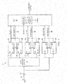
- FIG. 1 shows a block diagram of digital video signal receiver 10 (commonly known in the art as a "set-top box") supporting fault tolerance through the provision of backup or alternate functionalities.
- the receiver 10 includes an input 12 that, for example, comprises a coaxial connection 14 for a free air antenna or satellite dish or combination thereof.
- the RF audio/video signal received through connection 14 is processed by a splitter 16 (for example, a four-way wideband splitter known in the art).
- the splitter 16 includes a plurality of outputs including two terrestrial signal outputs 18 and 20 and two satellite signal outputs 22 and 24.
- the first terrestrial signal output 18 is connected to a first terrestrial front end receiver circuit 26.
- the second terrestrial signal output 20 is connected to a second terrestrial front end receiver circuit 28.
- the second terrestrial front end receiver circuit 28 may comprise a backup or alternate circuit for the first terrestrial front end receiver circuit 26.
- the first terrestrial front end receiver circuit 26 is the primary front end circuit functionality and the second terrestrial front end receiver circuit 28 is a secondary or redundant front end circuit functionality.
- the first and second terrestrial front end receiver circuits 26 and 28 each include an enable control input 30 fed by a terrestrial enable signal (Chip_Enable_T) 32.
- the first and second terrestrial front end receiver circuits 26 and 28 are enabled in a mutually exclusive manner. The enabled one of the first and second terrestrial front end receiver circuits 26 and 28 generates a received signal TS_Terr for further processing.
- the first satellite signal output 22 is connected to a first satellite front end receiver circuit 34.
- the second satellite signal output 24 is connected to a second satellite front end receiver circuit 36.
- the second satellite front end receiver circuit 36 may comprise a backup or alternate circuit for the first satellite front end receiver circuit 34.
- the first satellite front end receiver circuit 34 is the primary front end circuit functionality and the second satellite front end receiver circuit 36 is a secondary or redundant front end circuit functionality.
- the first and second satellite front end receiver circuits 34 and 36 each include an enable control input 38 fed by a satellite enable signal (Chip_Enable_S) 40.
- the first and second satellite front end receiver circuits 34 and 36 are enabled in a mutually exclusive manner. The enabled one of the first and second satellite front end receiver circuits 34 and 36 generates a received signal TS_Sat for further processing.
- Antenna control such as that known in the art as smart-antenna or satellite multi-switch, is exemplified here with low-noise block (LNB) control.
- the digital video signal received through connection 14 is further received by a first LNB downconverter control circuit 42 and a second LNB downconverter control circuit 44.
- the second LNB downconverter control circuit 44 may comprise a backup or alternate circuit for the first LNB downconverter control circuit 42.
- the first LNB downconverter control circuit 42 the primary downconverter circuit and the second LNB downconverter control circuit 44 is a secondary or redundant downconverter circuit functionality.
- the first and second LNB downconverter control circuits 42 and 44 each include an enable control input 46 fed by a downconverter enable signal (Chip_Enable_L) 48.
- the first and second LNB downconverter control circuits 42 and 44 are enabled in a mutually exclusive manner with the SoC using an antenna bi-directional control protocol (e.g., DiSEqC 2.0) to identify the LNBs uniquely.
- the enabled one of the first and second LNB downconverter control circuits 42 and 44 generates a received signal LNB_Controt for further processing.
- the received TS_Terr signal, TS_Sat signal and LNB_Control signal are passed to a System on Chip (SoC) 50 which functions to process the signals and generate an audio/video output signal.
- SoC System on Chip
- the audio/video signal processing performed by the System on Chip (SoC) 50 is well known to those skilled in the art and will not be discussed in detail herein.
- SoC System on Chip
- the System on Chip (SoC) 50 performs the standard signal processing functions with respect to the received TS_Terr signal and TS_Sat signal to generate the output audio/video signal.
- the System on Chip (SoC) 50 further comprises a fault detection circuit (Fault) 52 which determines whether there is a fault in, failure of, or mal-performance by a primary functionality of the system 10, and in response to such a determination activate the provided backup or alternate functionality.
- the fault detection circuit 52 operates to process sensed values for operational parameters of the receiver 10, and in particular sensed values concerning operation of the first and second terrestrial front end receiver circuits 26 and 28, the first and second satellite front end receiver circuits 34 and 36 and the first and second LNB downconverter control circuits 42 and 44.
- the processing performed by the fault detection circuit 52 makes a fault, failure or mal-performance determination based on the sensed values for operational parameters and controls the generation of the terrestrial enable signal (Chip_Enable_T) 32, satellite enable signal (Chip_Enable_S) 40 and downconverter enable signal (Chip_Enable_L) 48 so as to selectively enable one of the first and second terrestrial front end receiver circuits 26 and 28, one of the first and second satellite front end receiver circuits 34 and 36 and one of the first and second LNB downconverter control circuits 42 and 44.
- the terrestrial enable signal Chip_Enable_T
- satellite enable signal Chip_Enable_S
- downconverter enable signal Chip_Enable_L
- the logic state of the terrestrial enable signal (Chip_Enable_T) 32 is switched to enable operation of the second terrestrial front end receiver circuit 28.
- the fault detection circuit 52 may comprise a microprocessor or microcontroller circuit within the SoC 50 that is configured, for example, through an appropriate programming, to process received operational parameter data as discussed herein and make a fault detection determination.
- the System on Chip (SoC) 50 further includes measurement circuitry 54 which is configured to measure operational parameters of the first and second terrestrial front end receiver circuits 26 and 28, the first and second satellite front end receiver circuits 34 and 36 and the first and second LNB downconverter control circuits 42 and 44.
- operational parameters measured by the measurement circuitry 54 include Carrier to Noise ratio (C/N), Bit Error Rate (BER), Tuner frequency offset, Polarity Voltage level, DiSEqC delay, and the like.
- C/N Carrier to Noise ratio
- BER Bit Error Rate
- Tuner frequency offset Polarity Voltage level
- DiSEqC delay DiSEqC delay
- the measured values of the operational parameters are reported to the fault detection circuit 52 which, as described generally above, processes the values, makes a fault, failure or mal-performance determination, and controls generation of the enable signals to make a selection between primary and backup or alternate functionalities supported by the system 10.
- the measurement circuit 54 may comprise any circuit configured to sense operation of the system 10 and its component parts and through such sensing make a measurement concerning performance with respect to desired operational parameters. Examples of the circuitry and functions of the measurement circuit 54 include Ts_Ter Error, Ts_Sat Error, Video Treshold of Visibility (ToV) error, maximum or minimum Automatic Gain Control (AGC), and the like.
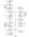
- FIG. 2 illustrates a flow diagram for operation of the fault detection circuit 52.
- This flow may, for example, represent the programming of the fault detection circuit 52 when implemented in the form of a microprocessor or microcontroller circuit within the SoC 50.
- step 100 initialization is made with respect to verifying the operation of primary functionality provided by the first LNB downconverter control circuit 42.
- This initialization includes using the measurement circuitry 54 to measure values for certain predefined operational parameters of the first LNB downconverter control circuit 42.
- measureable operational parameters for a LNB downconverter control circuit include DiSEqC delay, DiSEqC Transmission error, Polarity voltage level, and the like.
- a mean equivalence value (EqVal) is calculated from the measured operational parameter values in a weighted comparison with ideal or nominal or expected parameter values for the LNB downconverter control circuit (i.e., a reference circuit).
- the fault detection circuit 52 moves to step 106 and an initialization is made with respect to verifying the operation of the second LNB downconverter control circuit 44.
- This initialization includes measuring values for certain predefined operational parameters of the second LNB downconverter control circuit 44. Examples of measureable operational parameters for a LNB downconverter control circuit include DiSEqC delay, DiSEqC Transmission error, Polarity voltage level, and the like.
- a mean equivalence value (EqVal) is calculated from the measured operational parameter values in a weighted comparison with ideal or nominal or expected parameter values for the LNB downconverter control circuit (i.e., a reference circuit).
- a set mean equivalence (Reference SME) value for an idealized representation of the second LNB
- the fault detection circuit 52 moves to step 114 where initialization is made with respect to verifying the operation of primary functionality provided by the first satellite front end receiver circuit 34.
- This initialization includes measuring values for certain predefined operational parameters of the first satellite front end receiver circuit 34. Examples of measureable operational parameters for a satellite front end receiver circuit include Insertion Loss (IL), Return Loss (RL), Adjacent Channel Interferance (ACI), Low RF Bit Error Rate (BER), High RF BER, and the like.
- a mean equivalence value (EqVal) is calculated from the measured operational parameter values in a weighted comparison with ideal or nominal or expected parameter values for the satellite front end receiver circuit (i.e., a reference circuit).
- the fault detection circuit 52 moves to step 120 and an initialization is made with respect to verifying the operation of the second satellite front end receiver circuit 36.
- This initialization includes measuring values for certain predefined operational parameters of the second satellite front end receiver circuit 36. Examples of measureable operational parameters for a satellite front end receiver circuit include Insertion Loss (IL), Return Loss (RL), Adjacent Channel Interferance (ACI), Low RF Bit Error Rate (BER), High RF BER, and the like.
- a mean equivalence value (EqVal) is calculated from the measured operational parameter values in a weighted comparison with ideal or nominal or expected parameter values for the satellite front end receiver circuit (i.e., a reference circuit).
- a set mean equivalence (Reference SME) value for an idealized representation of the second satellite front end receiver circuit 36 (which may, for example, be
- the fault detection circuit 52 moves to step 126 where initialization is made with respect to verifying the operation of the first terrestrial front end receiver circuit 26.
- This initialization includes measuring values for certain predefined operational parameters of the first terrestrial front end receiver circuit 26. Examples of measureable operational parameters for a terrestrial front end receiver circuit include Insertion Loss (IL), Return Loss (RL), Adjacent Channel Interferance (ACI), Low RF Bit Error Rate (BER), High RF BER, and the like.
- a mean equivalence value (EqVal) is calculated from the measured operational parameter values in a weighted comparison with ideal or nominal or expected parameter values for the terrestrial front end receiver circuit (i.e., a reference circuit).
- the fault detection circuit 52 moves to step 132 and an initialization is made with respect to verifying the operation of the second terrestrial front end receiver circuit 28.
- This initialization includes measuring values for certain predefined operational parameters of the second terrestrial front end receiver circuit 28. Examples of measureable operational parameters for a terrestrial front end receiver circuit include Insertion Loss (IL), Return Loss (RL), Adjacent Channel Interferance (ACI), Low RF Bit Error Rate (BER), High RF BER.
- a mean equivalence value (EqVal) is calculated from the measured operational parameter values in a weighted comparison with ideal or nominal or expected parameter values for the terrestrial front end receiver circuit (i.e., a reference circuit).
- a set mean equivalence (Reference SME) value for an idealized representation of the second terrestrial front end receiver circuit 28 (which may, for example,
- the fault detection circuit 52 ends at step 138 with a completed verification and selective enabling of the primary and backup or alternate functionalities supported by the system 10.
- the process of Figure 2 may be performed at system configuration or initialization, such as at start-up. Alternatively, the process of Figure 2 may be performed during system operation. The process of Figure 2 may be performed one time for each system activation, or alternatively performed multiple times, including being performed periodically, if desired.
- the order of testing the various functionalities of the system 10 is exemplary only.
- steps 100, 102, 16, 108, 114, 116, 120, 122, 126, 128, 132 and 134 comprise processes for identifying equivalence between systems.
- the processes determine equivalence between the system functionality and an idealized (or nominal) functionality based on a predetermined set of parameters, measured and expected values for those parameters, and a relative weighting of those parameters.
- the system functionality may then be identified as being negligibly dissimilar from the idealized (or nominal) functionality (and thus enabled for operation) or reasonably unlike the idealized (or nominal) functionality (and thus indicating the presence of a fault).
- the system functionality may be disabled from operation and, if supported by the system, replaced by a backup or alternate functionality.
- the system 10 accordingly may perform, as a consistency/verification check using its driver software or embedded firmware in the form of the fault detection circuit 52, for example as part of an initialization/configuration process for the SoC 50, an equivalence test to verify that functionalities, devices and blocks within the system 10 are working as expected.
- the fault detection circuit 52 can also use this equivalence testing to enable fault tolerance on key system functionalities, devices and blocks; that is, if a functionality, device or block of the system seems to have failed in view of the equivalence testing, an available alternate functionality, device or block may be activated in its place.
- the program flow for such a system may be described in accordance with the following pseudo code (see, also Figure 2 ):
- a reference system functionality is identified by a basis set of parameters.
- the ideal (or nominal) representation of that reference system functionality has an expected value associated for each of these parameters.
- the expected value of any parameter is derived from the applicable distribution of possible values associated with correct (or permissible) operation of the reference functionality.
- typical distributions used in this context include: a NORMAL distribution which is defined by Mean, Standard Deviation parameter values, a POISSON distribution which is defined by Mean parameter values, a TRIANGULAR distribution which is defined by Minimum, Mode, and Maximum parameter values, and a UNIFORM distribution which is defined by Minimum and Maximum parameter values.
- Other distributions known in the art could also be used with respect to a given parameter value.
- Three sets are used for defining the reference system functionality and calculating equivalence.
- a first set is referred to as the Parameter Set and is designated as follows:
- the membership of the Parameter Set includes desired reference system functionality parameters (such as, for example, operational parameters).
- a second set is referred to as the Normative Value Set and is designated as follows:
- the membership of the Normative Value Set includes the expected value of the parameter identified in the Parameter Set.
- the expected value is a single value for the identified parameter.
- the expected value is expressed by a distribution.
- examples of distributions for use in the Normative Value Set include: a NORMAL distribution, a POISSON distribution, a TRIANGULAR distribution, and a UNIFORM distribution.
- a third set is referred to as the Weighting Set and is designated as follows:
- the membership of the Weighting Set includes a weight value assigned to each parameter identified in the Parameter Set.
- the weight value reflects the fraction that functionality parameter and its value contributes to the equivalence determination.
- a weight value of 4 for example, for Param1 in a Weighting Set: ⁇ 4,1,1,4 ⁇ indicates that the analysis of ExpectedVal1 contributes 40% (4/ ⁇ 4+1+1+4 ⁇ ) to the equivalence determination.
- the value of P represents a percentage value which must be equaled or exceeded in order for equivalence between the system functionality under test and the reference system functionality to be found.
- certain operational parameters for the functionalities of the system 10 are identified to define, for each such functionality, a Parameter Set: ⁇ Param1, Param2, ... , ParamN ⁇ .
- an expected value is provided for each parameter to define the Normative Value Set: ⁇ ExpectedVal1, ExpectedVal2, ... , ExpectedValN ⁇ .
- a weight value is assigned to each parameter identified in the Parameter Set to define the Weighting Set: ⁇ W1, W2, ... , WN ⁇ .
- a Set Mean Equivalence percentage P value is assigned.
- the parameters are measured by the measurement circuitry 54 of the SoC 50 and a measured parameter set, referred to as the A Set, for the functionality under test is designated as follows:
- the actual functionality in system 10 is considered to have equivalence with the ideal or nominal operation of that system (reference) functionality. In other words, there is no instance of a fault, failure or mal-performance.
- the tests in steps 102, 108, 116, 122, 128 or 134 would be satisfied and the given functionality would be enabled for operation.
- the calculated EqVal does not meet or exceed the Set Mean Equivalence percentage P value
- the actual functionality in system 10 is considered to not have equivalence with the ideal or nominal operation of that system (reference) functionality. In other words, there is an instance of a fault, failure or mal-performance.
- the tests in steps 102, 108, 116, 122, 128 or 134 would be failed and the given functionality would be not be enabled for operation.
- Weight values are assigned to each parameter identified in the Parameter Set to produce a Weighting Set defined as:
- This particular weighting set indicates that a greater weight for correspondence between the measured values of the system under test to the expected values is being given to the Low RF performance (LRF) and High RF performance (HRF) than the other parameters.
- the measurement circuitry 54 of the SoC 50 is configured to make measurements on the Insertion Loss (IL), Return Loss (RL), ACI Performance (ACI), Low RF performance (LRF), and High RF performance (HRF) on the primary functionality of the system 10 (the functionality under test).
- a measured parameter set referred to as the A Set, is thus obtained from measurement circuitry 54 parameter measurements as follows:
- EqVal SUM 0.92 * 1 / 30 , 0.92 * 4 / 30 , 0.75 * 5 / 30 , 0.91 * 10 / 30 , 0.93 * 10 / 30 * 100
- EqVal 0.031 + 0.123 + 0.125 + 0.303 + 0.310
- EqVal 89.2 %
- the fault detection circuit 52 would instead activate the backup or alternate functionality if available. If no backup or alternate functionality is available, then a system fault may be indicated.
- the measurement circuitry 54 of the SoC 50 would further be configured to make measurements on the Insertion Loss (IL), Return Loss (RL), ACI Performance (ACI), Low RF performance (LRF), and High RF performance (HRF) on the backup or alternate functionality of the system 10.
- a measured parameter set referred to as the A Set, is thus obtained from measurement circuitry 54 parameter measurements as follows:
- EqVal SUM 0.96 * 1 / 30 , 0.96 * 4 / 30 , 0.76 * 5 / 30 , 0.95 * 10 / 30 , 0.97 * 10 / 30 * 100
Landscapes
- Engineering & Computer Science (AREA)
- Signal Processing (AREA)
- Multimedia (AREA)
- Physics & Mathematics (AREA)
- Astronomy & Astrophysics (AREA)
- General Physics & Mathematics (AREA)
- Computer Networks & Wireless Communication (AREA)
- Databases & Information Systems (AREA)
- Monitoring And Testing Of Transmission In General (AREA)
- Hardware Redundancy (AREA)
Abstract
Description
- The present invention relates to systems implementing fault tolerance and, in particular but not exclusively, to a method and apparatus for monitoring system operation and activating alternate functionality in response to a detected fault.
- It is common in complex systems, such as electric circuits, for certain critical functionalities to be supported by a backup or alternate functionality. In response to a detected fault in, failure of, or mal-performance by a primary functionality of the system, the provided backup or alternate functionality is activated. In this way, continued operation of the complex system is supported in spite of the primary functionality's fault, failure or mal-performance.
- Some embodiments may be directed to a means for making the fault, failure or mal-performance detection. The operation of a primary functionality of a complex system is characterized by a set of parameters and, considering an ideal or nominal (or reference) representation of the primary functionality, an expected value for each of those parameters. The expected value is derived from an applicable distribution of possible (acceptable) values indicative of proper operation. Measured values of the parameters for the primary functionality are then obtained, and a mean equivalence level is calculated between the measured operation of the primary functionality and the ideal representation of the primary functionality. If the mean equivalence indicates that the primary functionality is not operating consistent with the ideal representation, a fault, failure or mal-performance detection is made. The complex system may then respond to that detection by replacing the primary functionality of the complex system with the backup or alternate functionality.
- In an embodiment, a system comprises: a primary functionality; a backup functionality for said primary functionality; a measurement circuit configured to measure a plurality of operational parameter values of the primary functionality; and a fault detection circuit configured to determine a level of equivalence between the operation of the primary functionality and a reference functionality based on a weighted comparison of said measured plurality of operational parameter values of the primary functionality to a corresponding plurality of reference operational parameter values for the reference functionality, said fault detection circuit further configured to identify a fault in said primary functionality based on the equivalence determination and activate the backup functionality in response thereto.
- In an embodiment, an apparatus comprises: a system under test; a measurement circuit configured to measure a plurality of values for operational parameters of a system under test, said operational parameters corresponding to a plurality of values for operational parameters of a reference system; and a control circuit configured to calculate an equivalence metric as a sum of relative percentages of the operational parameter values for the system under test versus the operational parameter values for the reference system and further control operation of the system under test in response to the calculated equivalence metric.
- In an embodiment, a method comprises: measuring a plurality of operational parameter values of a primary functionality; determining a level of equivalence between the operation of the primary functionality and a reference functionality based on a weighted comparison of said measured plurality of operational parameter values of the primary functionality to a corresponding plurality of reference operational parameter values for the reference functionality; detecting a fault in said primary functionality based on the equivalence determination; and activating a backup functionality in response to the detected fault.
- In an embodiment, a method for determining an equivalence level to a reference system defined by a plurality of values for operational parameters comprises: measuring a plurality of values for corresponding operational parameters of a system under test; calculating an equivalence metric as a sum of relative percentages of the operational parameter values for the system under test versus the operational parameter values for the reference system; and controlling operation of the system under test in response to the calculated equivalence metric.
- According to an aspect, there is provided a system, comprising: a primary functionality; a backup functionality for said primary functionality; a measurement circuit configured to measure a plurality of operational parameter values of the primary functionality; and a fault detection circuit configured to determine a level of equivalence between the operation of the primary functionality and a reference functionality based on a weighted comparison of said measured plurality of operational parameter values of the primary functionality to a corresponding plurality of reference operational parameter values for the reference functionality, said fault detection circuit further configured to identify a fault in said primary functionality based on the equivalence determination and activate the backup functionality in response thereto.
- The determined level of equivalence may be calculated based on the following formula:

wherein ExpectedVal is the reference operational parameter value;
A is the measured operational parameter value;
W is the weight; and
R(x,y)= min {x/y, y/x}. - In some embodiments, no fault is identified if EqVal meets or exceeds a threshold.
- In some embodiments, a fault is identified if EqVal is less than a threshold.
- In some embodiments, no fault is identified if operation of the primary functionality and the reference functionality are determined to be equivalent.
- In some embodiments, a fault is identified if operation of the primary functionality and the reference functionality are determined not to be equivalent.
- The measurement circuit may further be configured to measure the plurality of operational parameter values of the backup functionality; and wherein the fault detection circuit is further configured to determine a level of equivalence between the operation of the backup functionality and the reference functionality based on a weighted comparison of said measured plurality of operational parameter values of the backup functionality to the corresponding plurality of reference operational parameter values for the reference functionality, and wherein said fault detection circuit is further configured to identify a fault in said backup functionality based on the equivalence determination.
- The primary functionality may be a front end circuit, and wherein the backup functionality may be a backup front end circuit, said front end circuit having operational parameters selected from the group consisting of Insertion Loss, Return Loss, ACI Performance, Low RF performance, and High RF performance.
- According to another aspect, there is provided a method, comprising: measuring a plurality of operational parameter values of a primary functionality; determining a level of equivalence between the operation of the primary functionality and a reference functionality based on a weighted comparison of said measured plurality of operational parameter values of the primary functionality to a corresponding plurality of reference operational parameter values for the reference functionality; detecting a fault in said primary functionality based on the equivalence determination; and activating a backup functionality in response to the detected fault.
- The determining the level of equivalence may comprise calculating an equivalence value based on the following formula:

wherein ExpectedVal is the reference operational parameter value;
A is the measured operational parameter value;
W is the weight; and
R(x,y)= min {x/y, y/x}. - The detecting the fault may comprise identifying no fault if EqVal meets or exceeds a threshold.
- The detecting the fault may comprise identifying a fault if EqVal is less than a threshold.
- The detecting the fault may comprise determining whether the operation of the primary functionality is equivalent to operation of the reference functionality.
- The method may comprise measuring a plurality of operational parameter values of the backup functionality; determining a level of equivalence between the operation of the backup functionality and the reference functionality based on a weighted comparison of said measured plurality of operational parameter values of the backup functionality to a corresponding plurality of reference operational parameter values for the reference functionality; detecting a fault in said backup functionality based on the equivalence determination.
- The primary functionality may be a front end circuit, and wherein the backup functionality may be a backup front end circuit, said front end circuit having operational parameters selected from the group consisting of Insertion Loss, Return Loss, ACI Performance, Low RF performance, and High RF performance.
- According to another aspect, there is provided a method for determining an equivalence level to a reference system defined by a plurality of values for operational parameters, comprising: measuring a plurality of values for corresponding operational parameters of a system under test; calculating an equivalence metric as a sum of relative percentages of the operational parameter values for the system under test versus the operational parameter values for the reference system; and controlling operation of the system under test in response to the calculated equivalence metric.
- The controlling may comprise switching to a backup system if the calculated equivalence metric indicates a failure of the system under test.
- The equivalence metric may be calculated in accordance with the following formula:

wherein ExpectedVal is the operational parameter value for the reference system;
A is the measured operational parameter value for the system under test;
W is a weight; and
R(x,y)= min {x/y, y/x}. - The sum of relative percentages may be a weighted sum of relative percentages.
- The method may further comprise comparing the calculated equivalence metric against a threshold, and wherein controlling comprises enabling operation of the system under test if the calculated equivalence metric meets or exceeds the threshold.
- The controlling may comprise disabling operation of the system under test and enabling a backup system if the calculated equivalence metric is less than the threshold.
- According to another aspect, there is provided an apparatus, comprising: a system under test; a measurement circuit configured to measure a plurality of values for operational parameters of a system under test, said operational parameters corresponding to a plurality of values for operational parameters of a reference system; and a control circuit configured to calculate an equivalence metric as a sum of relative percentages of the operational parameter values for the system under test versus the operational parameter values for the reference system and further control operation of the system under test in response to the calculated equivalence metric.
- The apparatus may comprise a backup system selectable to replace the system under test, said control circuit configured to switch to the backup system if the calculated equivalence metric indicates a failure of the system under test.
- The equivalence metric may be calculated in accordance with the following formula:

wherein ExpectedVal is the operational parameter value for the reference system;
A is the measured operational parameter value for the system under test;
W is a weight; and
R(x,y)= min {x/y, y/x}. - The sum of relative percentages may be a weighted sum of relative percentages.
- The control circuit may further be configured to compare the calculated equivalence metric against a threshold, and wherein controlling operation comprises enabling operation of the system under test if the calculated equivalence metric meets or exceeds the threshold.
- The controlling may comprise disabling operation of the system under test and enabling a backup system if the calculated equivalence metric is less than the threshold.
- For a better understanding of the embodiments, reference will now be made by way of example only to the accompanying figures in which:
-
Figure 1 is a block diagram of digital video signal receiver supporting fault tolerance through the provision of backup or alternate functionalities; and -
Figure 2 is a flow diagram illustrating operation of a fault detection circuit for the receiver ofFigure 1 . -
Figure 1 shows a block diagram of digital video signal receiver 10 (commonly known in the art as a "set-top box") supporting fault tolerance through the provision of backup or alternate functionalities. Thereceiver 10 includes aninput 12 that, for example, comprises acoaxial connection 14 for a free air antenna or satellite dish or combination thereof. The RF audio/video signal received throughconnection 14 is processed by a splitter 16 (for example, a four-way wideband splitter known in the art). Thesplitter 16 includes a plurality of outputs including two terrestrial signal outputs 18 and 20 and two satellite signal outputs 22 and 24. - The first
terrestrial signal output 18 is connected to a first terrestrial frontend receiver circuit 26. The secondterrestrial signal output 20 is connected to a second terrestrial frontend receiver circuit 28. The second terrestrial frontend receiver circuit 28 may comprise a backup or alternate circuit for the first terrestrial frontend receiver circuit 26. In other words, the first terrestrial frontend receiver circuit 26 is the primary front end circuit functionality and the second terrestrial frontend receiver circuit 28 is a secondary or redundant front end circuit functionality. The first and second terrestrial frontend receiver circuits control input 30 fed by a terrestrial enable signal (Chip_Enable_T) 32. In the illustrated implementation, the first and second terrestrial frontend receiver circuits end receiver circuits - The first
satellite signal output 22 is connected to a first satellite frontend receiver circuit 34. The secondsatellite signal output 24 is connected to a second satellite frontend receiver circuit 36. The second satellite frontend receiver circuit 36 may comprise a backup or alternate circuit for the first satellite frontend receiver circuit 34. In other words, the first satellite frontend receiver circuit 34 is the primary front end circuit functionality and the second satellite frontend receiver circuit 36 is a secondary or redundant front end circuit functionality. The first and second satellite frontend receiver circuits control input 38 fed by a satellite enable signal (Chip_Enable_S) 40. In the illustrated implementation, the first and second satellite frontend receiver circuits end receiver circuits - Antenna control, such as that known in the art as smart-antenna or satellite multi-switch, is exemplified here with low-noise block (LNB) control. The digital video signal received through
connection 14 is further received by a first LNBdownconverter control circuit 42 and a second LNBdownconverter control circuit 44. The second LNBdownconverter control circuit 44 may comprise a backup or alternate circuit for the first LNBdownconverter control circuit 42. In other words, the first LNBdownconverter control circuit 42 the primary downconverter circuit and the second LNBdownconverter control circuit 44 is a secondary or redundant downconverter circuit functionality. The first and second LNBdownconverter control circuits control input 46 fed by a downconverter enable signal (Chip_Enable_L) 48. In the illustrated implementation, the first and second LNBdownconverter control circuits downconverter control circuits - The received TS_Terr signal, TS_Sat signal and LNB_Control signal are passed to a System on Chip (SoC) 50 which functions to process the signals and generate an audio/video output signal. The audio/video signal processing performed by the System on Chip (SoC) 50 is well known to those skilled in the art and will not be discussed in detail herein. Generally speaking, the System on Chip (SoC) 50 performs the standard signal processing functions with respect to the received TS_Terr signal and TS_Sat signal to generate the output audio/video signal.
- The System on Chip (SoC) 50 further comprises a fault detection circuit (Fault) 52 which determines whether there is a fault in, failure of, or mal-performance by a primary functionality of the
system 10, and in response to such a determination activate the provided backup or alternate functionality. Thefault detection circuit 52 operates to process sensed values for operational parameters of thereceiver 10, and in particular sensed values concerning operation of the first and second terrestrial frontend receiver circuits end receiver circuits downconverter control circuits fault detection circuit 52 makes a fault, failure or mal-performance determination based on the sensed values for operational parameters and controls the generation of the terrestrial enable signal (Chip_Enable_T) 32, satellite enable signal (Chip_Enable_S) 40 and downconverter enable signal (Chip_Enable_L) 48 so as to selectively enable one of the first and second terrestrial frontend receiver circuits end receiver circuits downconverter control circuits fault detection circuit 52 detects a failure of the first terrestrial frontend receiver circuit 26 as indicated by processing of the sensed values forcircuit 26 operational parameters, the logic state of the terrestrial enable signal (Chip_Enable_T) 32 is switched to enable operation of the second terrestrial frontend receiver circuit 28. - The
fault detection circuit 52 may comprise a microprocessor or microcontroller circuit within theSoC 50 that is configured, for example, through an appropriate programming, to process received operational parameter data as discussed herein and make a fault detection determination. - The System on Chip (SoC) 50 further includes
measurement circuitry 54 which is configured to measure operational parameters of the first and second terrestrial frontend receiver circuits end receiver circuits downconverter control circuits measurement circuitry 54 include Carrier to Noise ratio (C/N), Bit Error Rate (BER), Tuner frequency offset, Polarity Voltage level, DiSEqC delay, and the like. The measured values of the operational parameters are reported to thefault detection circuit 52 which, as described generally above, processes the values, makes a fault, failure or mal-performance determination, and controls generation of the enable signals to make a selection between primary and backup or alternate functionalities supported by thesystem 10. - The
measurement circuit 54 may comprise any circuit configured to sense operation of thesystem 10 and its component parts and through such sensing make a measurement concerning performance with respect to desired operational parameters. Examples of the circuitry and functions of themeasurement circuit 54 include Ts_Ter Error, Ts_Sat Error, Video Treshold of Visibility (ToV) error, maximum or minimum Automatic Gain Control (AGC), and the like. - Reference is now made to
Figure 2 which illustrates a flow diagram for operation of thefault detection circuit 52. This flow may, for example, represent the programming of thefault detection circuit 52 when implemented in the form of a microprocessor or microcontroller circuit within theSoC 50. - In
step 100, initialization is made with respect to verifying the operation of primary functionality provided by the first LNBdownconverter control circuit 42. This initialization includes using themeasurement circuitry 54 to measure values for certain predefined operational parameters of the first LNBdownconverter control circuit 42. Examples of measureable operational parameters for a LNB downconverter control circuit include DiSEqC delay, DiSEqC Transmission error, Polarity voltage level, and the like. A mean equivalence value (EqVal) is calculated from the measured operational parameter values in a weighted comparison with ideal or nominal or expected parameter values for the LNB downconverter control circuit (i.e., a reference circuit). - The calculated mean equivalence value (LNB SME = EqVal) is then compared in
step 102 with a set mean equivalence (Reference SME) value for an idealized representation of the first LNBdownconverter control circuit 42. If the mean equivalence value exceeds the reference SME value, the first LNBdownconverter control circuit 42 is considered to be operating properly and thefault detection circuit 52 moves to step 104 and enables the first LNBdownconverter control circuit 42, for example, by setting Chip_Enable_L to a first logic state. - If the mean equivalence value (LNB SME) does not exceed the reference SME value, the
fault detection circuit 52 moves to step 106 and an initialization is made with respect to verifying the operation of the second LNBdownconverter control circuit 44. This initialization includes measuring values for certain predefined operational parameters of the second LNBdownconverter control circuit 44. Examples of measureable operational parameters for a LNB downconverter control circuit include DiSEqC delay, DiSEqC Transmission error, Polarity voltage level, and the like. A mean equivalence value (EqVal) is calculated from the measured operational parameter values in a weighted comparison with ideal or nominal or expected parameter values for the LNB downconverter control circuit (i.e., a reference circuit). - The calculated mean equivalence value (LNB_ALT SME = EqVal) is then compared in
step 108 with a set mean equivalence (Reference SME) value for an idealized representation of the second LNB downconverter control circuit 44 (which may, for example, be identical to the idealized representation of the first LNB downconverter control circuit 42). If the calculated mean equivalence value exceeds the reference SME value, the second LNBdownconverter control circuit 44 is considered to be operating properly and thefault detection circuit 52 moves to step 110 and enables the second LNB downconverter control circuit 44 (as a backup or alternate functionality to the first LNB downconverter control circuit 42), for example, by setting Chip_Enable_L to a second logic state. If the calculated mean equivalence value does not exceed the reference SME value, thefault detection circuit 52 moves to step 112 to issue a system fault notice. - From step 110 (or alternatively from step 112), the
fault detection circuit 52 moves to step 114 where initialization is made with respect to verifying the operation of primary functionality provided by the first satellite frontend receiver circuit 34. This initialization includes measuring values for certain predefined operational parameters of the first satellite frontend receiver circuit 34. Examples of measureable operational parameters for a satellite front end receiver circuit include Insertion Loss (IL), Return Loss (RL), Adjacent Channel Interferance (ACI), Low RF Bit Error Rate (BER), High RF BER, and the like. A mean equivalence value (EqVal) is calculated from the measured operational parameter values in a weighted comparison with ideal or nominal or expected parameter values for the satellite front end receiver circuit (i.e., a reference circuit). - The calculated mean equivalence value (Sat FE SME = EqVal) is then compared in
step 116 with a set mean equivalence (Reference SME) value for an idealized representation of the first satellite frontend receiver circuit 34. If the calculated mean equivalence value exceeds the reference SME value, the first satellite frontend receiver circuit 34 is considered to be operating properly and thefault detection circuit 52 moves to step 118 and enables the first satellite frontend receiver circuit 34, for example, by setting Chip_Enable_S to a first logic state. - If the calculated mean equivalence value does not exceed the reference SME value, the
fault detection circuit 52 moves to step 120 and an initialization is made with respect to verifying the operation of the second satellite frontend receiver circuit 36. This initialization includes measuring values for certain predefined operational parameters of the second satellite frontend receiver circuit 36. Examples of measureable operational parameters for a satellite front end receiver circuit include Insertion Loss (IL), Return Loss (RL), Adjacent Channel Interferance (ACI), Low RF Bit Error Rate (BER), High RF BER, and the like. A mean equivalence value (EqVal) is calculated from the measured operational parameter values in a weighted comparison with ideal or nominal or expected parameter values for the satellite front end receiver circuit (i.e., a reference circuit). - The calculated mean equivalence value (Sat FE_ALT SME = EqVal) is then compared in
step 122 with a set mean equivalence (Reference SME) value for an idealized representation of the second satellite front end receiver circuit 36 (which may, for example, be identical to the idealized representation of the first satellite front end receiver circuit 34). If the calculated mean equivalence value exceeds the reference SME value, the second satellite frontend receiver circuit 36 is considered to be operating properly and thefault detection circuit 52 moves to step 124 and enables the second satellite front end receiver circuit 36 (as a backup or alternate functionality to the first satellite front end receiver circuit 34), for example, by setting Chip_Enable_S to a second logic state. If the calculated mean equivalence value does not exceed the reference SME value, thefault detection circuit 52 moves to step 112 to issue a system fault notice. - From step 122 (or alternatively from step 112), the
fault detection circuit 52 moves to step 126 where initialization is made with respect to verifying the operation of the first terrestrial frontend receiver circuit 26. This initialization includes measuring values for certain predefined operational parameters of the first terrestrial frontend receiver circuit 26. Examples of measureable operational parameters for a terrestrial front end receiver circuit include Insertion Loss (IL), Return Loss (RL), Adjacent Channel Interferance (ACI), Low RF Bit Error Rate (BER), High RF BER, and the like. A mean equivalence value (EqVal) is calculated from the measured operational parameter values in a weighted comparison with ideal or nominal or expected parameter values for the terrestrial front end receiver circuit (i.e., a reference circuit). - The calculated mean equivalence value (Terr FE SME = EqVal) is then compared in
step 128 with a set mean equivalence (Reference SME) value for an idealized representation of the first terrestrial frontend receiver circuit 26. If the calculated mean equivalence value exceeds the reference SME value, the first terrestrial frontend receiver circuit 26 is considered to be operating properly and thefault detection circuit 52 moves to step 130 and enables the first terrestrial frontend receiver circuit 26, for example, by setting Chip_Enable_T to a first logic state. - If the calculated mean equivalence value does not exceed the reference SME value, the
fault detection circuit 52 moves to step 132 and an initialization is made with respect to verifying the operation of the second terrestrial frontend receiver circuit 28. This initialization includes measuring values for certain predefined operational parameters of the second terrestrial frontend receiver circuit 28. Examples of measureable operational parameters for a terrestrial front end receiver circuit include Insertion Loss (IL), Return Loss (RL), Adjacent Channel Interferance (ACI), Low RF Bit Error Rate (BER), High RF BER. A mean equivalence value (EqVal) is calculated from the measured operational parameter values in a weighted comparison with ideal or nominal or expected parameter values for the terrestrial front end receiver circuit (i.e., a reference circuit). - The calculated mean equivalence value (Terr FE_ALT SME = EqVal) is then compared in
step 134 with a set mean equivalence (Reference SME) value for an idealized representation of the second terrestrial front end receiver circuit 28 (which may, for example, be identical to the idealized representation of the first terrestrial front end receiver circuit 26). If the calculated mean equivalence value exceeds the reference SME value, the second terrestrial frontend receiver circuit 28 is considered to be operating properly and thefault detection circuit 52 moves to step 136 and enables the second terrestrial front end receiver circuit 28 (as a backup or alternate functionality to the first terrestrial front end receiver circuit 26), for example, by setting Chip_Enable_T to a second logic state. If the calculated mean equivalence value does not exceed the reference SME value, thefault detection circuit 52 moves to step 112 to issue a system fault notice. - After testing each of the functionalities as described above, the
fault detection circuit 52 ends atstep 138 with a completed verification and selective enabling of the primary and backup or alternate functionalities supported by thesystem 10. - The process of
Figure 2 may be performed at system configuration or initialization, such as at start-up. Alternatively, the process ofFigure 2 may be performed during system operation. The process ofFigure 2 may be performed one time for each system activation, or alternatively performed multiple times, including being performed periodically, if desired. The order of testing the various functionalities of thesystem 10 is exemplary only. - The operations performed in
steps - The
system 10 accordingly may perform, as a consistency/verification check using its driver software or embedded firmware in the form of thefault detection circuit 52, for example as part of an initialization/configuration process for theSoC 50, an equivalence test to verify that functionalities, devices and blocks within thesystem 10 are working as expected. Thefault detection circuit 52 can also use this equivalence testing to enable fault tolerance on key system functionalities, devices and blocks; that is, if a functionality, device or block of the system seems to have failed in view of the equivalence testing, an available alternate functionality, device or block may be activated in its place. The program flow for such a system may be described in accordance with the following pseudo code (see, alsoFigure 2 ): - 0) SoC system has N systems (System); each with 0 or more alternates (AltSystem)
- 1) Initialize system matrix (array of parameter set values and weights as well as the respective reference value sets); identify the Set Mean Equivalence (SME) value,
- 2) For i=1;N;i++
               if !(EqVal of System(i) ≥ Mean Set Equivalence)
                      {
                             Set System(i) inactive)
                                     if AltSystem (i)
                                            if !(EqVal of AltSystem(i) ≥ Mean Set Equivalence)
                                                   return SoC failure
                                    else set AltSystem(i) active
                      }
               else set System(i) active
- Parameter Set: {Param1, Param2, ... , ParamN}
- Normative Value Set: {ExpectedVal1, ExpectedVal2, ... , ExpectedValN}
- Weighting Set: {W1, W2, ... , WN}
- Set Mean Equivalence >= P%
- A Set: {A1, A2, ... , AN}

wherein:

- Parameter Set: {IL, RL, ACI, LRF, HRF}
- Normative Value Set: {0.25 dB, -13dB, BER of 2.2e-9, BER of 2.1e-9, BER of 2.9e-9}.
- Weighting Set: {1, 4, 5, 10, 10}.
- A Set: {0.23, -12.0, 2.9e-9, 2.3e-9, 3.1e-9}


- A Set: {0.24, -12.5, 2.9e-9, 2.2e-9, 3.0e-9}


Claims (15)
- A system, comprising:a primary functionality;a backup functionality for said primary functionality;a measurement circuit configured to measure a plurality of operational parameter values of the primary functionality; anda fault detection circuit configured to determine a level of equivalence between the operation of the primary functionality and a reference functionality based on a weighted comparison of said measured plurality of operational parameter values of the primary functionality to a corresponding plurality of reference operational parameter values for the reference functionality, said fault detection circuit further configured to identify a fault in said primary functionality based on the equivalence determination and activate the backup functionality in response thereto.
- A method, comprising:measuring a plurality of operational parameter values of a primary functionality;determining a level of equivalence between the operation of the primary functionality and a reference functionality based on a weighted comparison of said measured plurality of operational parameter values of the primary functionality to a corresponding plurality of reference operational parameter values for the reference functionality;detecting a fault in said primary functionality based on the equivalence determination; andactivating a backup functionality in response to the detected fault.
- Apparatus, comprising:a system under test;a measurement circuit configured to measure a plurality of values for operational parameters of a system under test, said operational parameters corresponding to a plurality of values for operational parameters of a reference system; anda control circuit configured to calculate an equivalence metric as a sum of relative percentages of the operational parameter values for the system under test versus the operational parameter values for the reference system and further control operation of the system under test in response to the calculated equivalence metric.
- A method for determining an equivalence level to a reference system defined by a plurality of values for operational parameters, comprising:measuring a plurality of values for corresponding operational parameters of a system under test;calculating an equivalence metric as a sum of relative percentages of the operational parameter values for the system under test versus the operational parameter values for the reference system; andcontrolling operation of the system under test in response to the calculated equivalence metric.
- A method, system or apparatus as claimed in any preceding claim wherein
the equivalence metric or level is calculated based on the following formula:
wherein ExpectedVal is the reference operational parameter value;
A is the measured operational parameter value;
W is the weight; and
R(x,y)= min {x/y, y/x}. - A method, system or apparatus as claimed in claim 5, wherein no fault is identified if EqVal meets or exceeds a threshold.
- A method, system or apparatus as claimed in claim 5 or 6, wherein a fault is identified if EqVal is less than a threshold.
- A system or method as claimed in claim 1 or 2 or any claim appended thereto, wherein a fault or no fault is identified in dependence on if operation of the primary functionality and the reference functionality are determined to be equivalent.
- The system of claim 1 or any claim appended thereto, wherein said measurement circuit is further configured to measure the plurality of operational parameter values of the backup functionality; and wherein the fault detection circuit is further configured to determine a level of equivalence between the operation of the backup functionality and the reference functionality based on a weighted comparison of said measured plurality of operational parameter values of the backup functionality to the corresponding plurality of reference operational parameter values for the reference functionality, and wherein said fault detection circuit is further configured to identify a fault in said backup functionality based on the equivalence determination.
- The method of claim 2 or any claim appended thereto, further comprising:measuring a plurality of operational parameter values of the backup functionality;determining a level of equivalence between the operation of the backup functionality and the reference functionality based on a weighted comparison of said measured plurality of operational parameter values of the backup functionality to a corresponding plurality of reference operational parameter values for the reference functionality;detecting a fault in said backup functionality based on the equivalence determination.
- The system of claim 1 or method of claim 2 or any claim appended thereto, wherein the primary functionality is a front end circuit, and wherein the backup functionality is a backup front end circuit, said front end circuit having operational parameters selected from the group consisting of Insertion Loss, Return Loss, ACI Performance, Low RF performance, and High RF performance.
- The method of claim 4 or any claim appended thereto, wherein controlling comprises switching to a backup system if the calculated equivalence metric indicates a failure of the system under test.
- The apparatus or method of claim 3 or 4 or any claim appended thereto, wherein the sum of relative percentages is a weighted sum of relative percentages.
- The method of claim 4 or any claim appended thereto, further comprising comparing the calculated equivalence metric against a threshold, and wherein controlling comprises enabling operation of the system under test if the calculated equivalence metric meets or exceeds the threshold.
- The method of claim 4 or any claim appended thereto, wherein controlling comprises disabling operation of the system under test and enabling a backup system if the calculated equivalence metric is less than the threshold.
Applications Claiming Priority (1)
| Application Number | Priority Date | Filing Date | Title |
|---|---|---|---|
| US13/474,286 US9197934B2 (en) | 2012-05-17 | 2012-05-17 | Fault tolerant system with equivalence processing driving fault detection and backup activation |
Publications (3)
| Publication Number | Publication Date |
|---|---|
| EP2713621A2 true EP2713621A2 (en) | 2014-04-02 |
| EP2713621A3 EP2713621A3 (en) | 2015-07-22 |
| EP2713621B1 EP2713621B1 (en) | 2021-06-30 |
Family
ID=48626258
Family Applications (1)
| Application Number | Title | Priority Date | Filing Date |
|---|---|---|---|
| EP13168197.5A Active EP2713621B1 (en) | 2012-05-17 | 2013-05-17 | Fault tolerant system with equivalence processsing driving fault detection and backup activation |
Country Status (2)
| Country | Link |
|---|---|
| US (1) | US9197934B2 (en) |
| EP (1) | EP2713621B1 (en) |
Families Citing this family (4)
| Publication number | Priority date | Publication date | Assignee | Title |
|---|---|---|---|---|
| DE102014118293A1 (en) * | 2014-12-10 | 2016-06-16 | Océ Printing Systems GmbH & Co. KG | System and method for monitoring a production system |
| US9934873B2 (en) | 2016-06-21 | 2018-04-03 | International Business Machines Corporation | Delayed equivalence identification |
| WO2018193590A1 (en) * | 2017-04-20 | 2018-10-25 | ヤマハ株式会社 | Information processing device and information processing method |
| US20180332338A1 (en) * | 2017-05-10 | 2018-11-15 | Kevin M. Hardee | Method and apparatus for satellite path protection for ip video networks |
Family Cites Families (13)
| Publication number | Priority date | Publication date | Assignee | Title |
|---|---|---|---|---|
| DE19743124B4 (en) | 1997-09-30 | 2004-08-26 | Harman Becker Automotive Systems (Xsys Division) Gmbh | Method for determining the quality of a video signal and / or a television picture |
| US6208296B1 (en) * | 1998-07-24 | 2001-03-27 | Sony Corporation | Method and apparatus for training a receiver on a source |
| US6996057B2 (en) * | 2001-10-05 | 2006-02-07 | Adtran, Inc. | Integrated RF loopback test apparatus for redundant data radio transceiver system |
| US8505063B2 (en) * | 2002-02-22 | 2013-08-06 | Qwest Communications International Inc. | Systems and methods for providing redundant back-up to a video transmission system |
| US6906526B2 (en) * | 2003-03-14 | 2005-06-14 | General Instrument Corporation | Non-intrusive cable connection monitoring for use in HFC networks |
| CA2481141A1 (en) * | 2003-09-10 | 2005-04-03 | Robert J. Robson | Audio broadcasting signal disruption sensor and backup program source |
| DE102004029421A1 (en) | 2004-06-18 | 2006-01-05 | Rohde & Schwarz Gmbh & Co. Kg | Method and device for evaluating the quality of a signal |
| US7647044B2 (en) * | 2005-08-24 | 2010-01-12 | Atx Networks Corp. | RF switching device |
| CA2637331A1 (en) * | 2006-01-17 | 2007-07-26 | Gulfstream Aerospace Corporation | System and method for an integrated backup control system |
| EP1857934B1 (en) * | 2006-05-16 | 2009-07-15 | Saab Ab | Fault tolerant control system |
| WO2009020861A1 (en) * | 2007-08-03 | 2009-02-12 | Smartsignal Corporation | Fuzzy classification approach to fault pattern matching |
| CN103609049B (en) * | 2011-02-16 | 2016-09-07 | 熵敏通讯公司 | The optical converter with channelization device based on ADC and method for optics LNB system |
| US8660980B2 (en) * | 2011-07-19 | 2014-02-25 | Smartsignal Corporation | Monitoring system using kernel regression modeling with pattern sequences |
-
2012
- 2012-05-17 US US13/474,286 patent/US9197934B2/en active Active
-
2013
- 2013-05-17 EP EP13168197.5A patent/EP2713621B1/en active Active
Non-Patent Citations (1)
| Title |
|---|
| None |
Also Published As
| Publication number | Publication date |
|---|---|
| US20130312051A1 (en) | 2013-11-21 |
| US9197934B2 (en) | 2015-11-24 |
| EP2713621B1 (en) | 2021-06-30 |
| EP2713621A3 (en) | 2015-07-22 |
Similar Documents
| Publication | Publication Date | Title |
|---|---|---|
| EP2713621B1 (en) | Fault tolerant system with equivalence processsing driving fault detection and backup activation | |
| CN104101831A (en) | Relay failure detection system | |
| US20180031635A1 (en) | Methods for switch health determination | |
| US20110248790A1 (en) | Apparatus and method for an a/b rf redundant sensing switch | |
| JP3139440B2 (en) | Antenna and its receiving circuit abnormality detecting device | |
| KR100720555B1 (en) | DM terminal having a reception sensitivity display function and a reception sensitivity display method using the same | |
| CN114217258A (en) | Error self-monitoring method of intelligent electric meter | |
| US11408917B2 (en) | Redundant current-measuring arrangement with detection of interruptions of an electric circuit | |
| US8225646B2 (en) | Throttle body sweep diagnostic system and method | |
| US7376404B2 (en) | System and method for detecting a fault in a multiple receiver system | |
| US9424118B2 (en) | Change message broadcast error detection | |
| US10284073B2 (en) | Power supply built-in testing | |
| EP2017541A1 (en) | Electric device and communication function normality judging method in the electric device | |
| WO2016132660A1 (en) | Monitoring device, wireless communication system, failure factor determination method and non-temporary computer-readable medium in which program is stored | |
| CN1893339B (en) | Continuous median failure control system and method | |
| JP7572140B2 (en) | Zero-phase current transformer health diagnostic method and power conditioner | |
| KR102304748B1 (en) | A method for sending Trip Information Packet at the Protective Relay Test | |
| US9092315B2 (en) | Method and software program product for determining the quality of an information technology system | |
| CN116755024A (en) | Test methods, test equipment and readable storage media for electric energy meter communication interfaces | |
| KR20220115342A (en) | Communication module | |
| JP4804151B2 (en) | Abnormality diagnosis apparatus for receiver, receiver, abnormality diagnosis method for receiver, and program | |
| US9698834B2 (en) | Intelligent RF redundancy switch | |
| CN222319343U (en) | A relay self-test circuit and function test system | |
| US20150036520A1 (en) | Monitoring of a differential multichannel transmission link | |
| CN111524341A (en) | RTU data acquisition method for gas industry |
Legal Events
| Date | Code | Title | Description |
|---|---|---|---|
| PUAI | Public reference made under article 153(3) epc to a published international application that has entered the european phase |
Free format text: ORIGINAL CODE: 0009012 |
|
| AK | Designated contracting states |
Kind code of ref document: A2 Designated state(s): AL AT BE BG CH CY CZ DE DK EE ES FI FR GB GR HR HU IE IS IT LI LT LU LV MC MK MT NL NO PL PT RO RS SE SI SK SM TR |
|
| AX | Request for extension of the european patent |
Extension state: BA ME |
|
| PUAL | Search report despatched |
Free format text: ORIGINAL CODE: 0009013 |
|
| AK | Designated contracting states |
Kind code of ref document: A3 Designated state(s): AL AT BE BG CH CY CZ DE DK EE ES FI FR GB GR HR HU IE IS IT LI LT LU LV MC MK MT NL NO PL PT RO RS SE SI SK SM TR |
|
| AX | Request for extension of the european patent |
Extension state: BA ME |
|
| RIC1 | Information provided on ipc code assigned before grant |
Ipc: H04N 21/426 20110101ALI20150616BHEP Ipc: H04N 17/00 20060101ALI20150616BHEP Ipc: H04H 40/90 20080101ALI20150616BHEP Ipc: H04N 21/61 20110101ALI20150616BHEP Ipc: H04L 1/22 20060101ALI20150616BHEP Ipc: H04N 21/4425 20110101AFI20150616BHEP Ipc: H04H 20/12 20080101ALI20150616BHEP |
|
| 17P | Request for examination filed |
Effective date: 20160121 |
|
| RBV | Designated contracting states (corrected) |
Designated state(s): AL AT BE BG CH CY CZ DE DK EE ES FI FR GB GR HR HU IE IS IT LI LT LU LV MC MK MT NL NO PL PT RO RS SE SI SK SM TR |
|
| STAA | Information on the status of an ep patent application or granted ep patent |
Free format text: STATUS: EXAMINATION IS IN PROGRESS |
|
| 17Q | First examination report despatched |
Effective date: 20170531 |
|
| GRAP | Despatch of communication of intention to grant a patent |
Free format text: ORIGINAL CODE: EPIDOSNIGR1 |
|
| STAA | Information on the status of an ep patent application or granted ep patent |
Free format text: STATUS: GRANT OF PATENT IS INTENDED |
|
| INTG | Intention to grant announced |
Effective date: 20200707 |
|
| GRAJ | Information related to disapproval of communication of intention to grant by the applicant or resumption of examination proceedings by the epo deleted |
Free format text: ORIGINAL CODE: EPIDOSDIGR1 |
|
| STAA | Information on the status of an ep patent application or granted ep patent |
Free format text: STATUS: EXAMINATION IS IN PROGRESS |
|
| INTC | Intention to grant announced (deleted) | ||
| GRAP | Despatch of communication of intention to grant a patent |
Free format text: ORIGINAL CODE: EPIDOSNIGR1 |
|
| STAA | Information on the status of an ep patent application or granted ep patent |
Free format text: STATUS: GRANT OF PATENT IS INTENDED |
|
| INTG | Intention to grant announced |
Effective date: 20210118 |
|
| GRAS | Grant fee paid |
Free format text: ORIGINAL CODE: EPIDOSNIGR3 |
|
| GRAA | (expected) grant |
Free format text: ORIGINAL CODE: 0009210 |
|
| STAA | Information on the status of an ep patent application or granted ep patent |
Free format text: STATUS: THE PATENT HAS BEEN GRANTED |
|
| AK | Designated contracting states |
Kind code of ref document: B1 Designated state(s): AL AT BE BG CH CY CZ DE DK EE ES FI FR GB GR HR HU IE IS IT LI LT LU LV MC MK MT NL NO PL PT RO RS SE SI SK SM TR |
|
| REG | Reference to a national code |
Ref country code: GB Ref legal event code: FG4D Ref country code: CH Ref legal event code: EP |
|
| REG | Reference to a national code |
Ref country code: AT Ref legal event code: REF Ref document number: 1407503 Country of ref document: AT Kind code of ref document: T Effective date: 20210715 |
|
| REG | Reference to a national code |
Ref country code: DE Ref legal event code: R096 Ref document number: 602013078118 Country of ref document: DE |
|
| REG | Reference to a national code |
Ref country code: IE Ref legal event code: FG4D |
|
| REG | Reference to a national code |
Ref country code: LT Ref legal event code: MG9D |
|
| PG25 | Lapsed in a contracting state [announced via postgrant information from national office to epo] |
Ref country code: FI Free format text: LAPSE BECAUSE OF FAILURE TO SUBMIT A TRANSLATION OF THE DESCRIPTION OR TO PAY THE FEE WITHIN THE PRESCRIBED TIME-LIMIT Effective date: 20210630 Ref country code: HR Free format text: LAPSE BECAUSE OF FAILURE TO SUBMIT A TRANSLATION OF THE DESCRIPTION OR TO PAY THE FEE WITHIN THE PRESCRIBED TIME-LIMIT Effective date: 20210630 Ref country code: BG Free format text: LAPSE BECAUSE OF FAILURE TO SUBMIT A TRANSLATION OF THE DESCRIPTION OR TO PAY THE FEE WITHIN THE PRESCRIBED TIME-LIMIT Effective date: 20210930 |
|
| REG | Reference to a national code |
Ref country code: NL Ref legal event code: MP Effective date: 20210630 |
|
| REG | Reference to a national code |
Ref country code: AT Ref legal event code: MK05 Ref document number: 1407503 Country of ref document: AT Kind code of ref document: T Effective date: 20210630 |
|
| PG25 | Lapsed in a contracting state [announced via postgrant information from national office to epo] |
Ref country code: RS Free format text: LAPSE BECAUSE OF FAILURE TO SUBMIT A TRANSLATION OF THE DESCRIPTION OR TO PAY THE FEE WITHIN THE PRESCRIBED TIME-LIMIT Effective date: 20210630 Ref country code: SE Free format text: LAPSE BECAUSE OF FAILURE TO SUBMIT A TRANSLATION OF THE DESCRIPTION OR TO PAY THE FEE WITHIN THE PRESCRIBED TIME-LIMIT Effective date: 20210630 Ref country code: GR Free format text: LAPSE BECAUSE OF FAILURE TO SUBMIT A TRANSLATION OF THE DESCRIPTION OR TO PAY THE FEE WITHIN THE PRESCRIBED TIME-LIMIT Effective date: 20211001 Ref country code: LV Free format text: LAPSE BECAUSE OF FAILURE TO SUBMIT A TRANSLATION OF THE DESCRIPTION OR TO PAY THE FEE WITHIN THE PRESCRIBED TIME-LIMIT Effective date: 20210630 Ref country code: NO Free format text: LAPSE BECAUSE OF FAILURE TO SUBMIT A TRANSLATION OF THE DESCRIPTION OR TO PAY THE FEE WITHIN THE PRESCRIBED TIME-LIMIT Effective date: 20210930 |
|
| PG25 | Lapsed in a contracting state [announced via postgrant information from national office to epo] |
Ref country code: SM Free format text: LAPSE BECAUSE OF FAILURE TO SUBMIT A TRANSLATION OF THE DESCRIPTION OR TO PAY THE FEE WITHIN THE PRESCRIBED TIME-LIMIT Effective date: 20210630 Ref country code: SK Free format text: LAPSE BECAUSE OF FAILURE TO SUBMIT A TRANSLATION OF THE DESCRIPTION OR TO PAY THE FEE WITHIN THE PRESCRIBED TIME-LIMIT Effective date: 20210630 Ref country code: CZ Free format text: LAPSE BECAUSE OF FAILURE TO SUBMIT A TRANSLATION OF THE DESCRIPTION OR TO PAY THE FEE WITHIN THE PRESCRIBED TIME-LIMIT Effective date: 20210630 Ref country code: EE Free format text: LAPSE BECAUSE OF FAILURE TO SUBMIT A TRANSLATION OF THE DESCRIPTION OR TO PAY THE FEE WITHIN THE PRESCRIBED TIME-LIMIT Effective date: 20210630 Ref country code: PT Free format text: LAPSE BECAUSE OF FAILURE TO SUBMIT A TRANSLATION OF THE DESCRIPTION OR TO PAY THE FEE WITHIN THE PRESCRIBED TIME-LIMIT Effective date: 20211102 Ref country code: RO Free format text: LAPSE BECAUSE OF FAILURE TO SUBMIT A TRANSLATION OF THE DESCRIPTION OR TO PAY THE FEE WITHIN THE PRESCRIBED TIME-LIMIT Effective date: 20210630 Ref country code: NL Free format text: LAPSE BECAUSE OF FAILURE TO SUBMIT A TRANSLATION OF THE DESCRIPTION OR TO PAY THE FEE WITHIN THE PRESCRIBED TIME-LIMIT Effective date: 20210630 Ref country code: ES Free format text: LAPSE BECAUSE OF FAILURE TO SUBMIT A TRANSLATION OF THE DESCRIPTION OR TO PAY THE FEE WITHIN THE PRESCRIBED TIME-LIMIT Effective date: 20210630 Ref country code: AT Free format text: LAPSE BECAUSE OF FAILURE TO SUBMIT A TRANSLATION OF THE DESCRIPTION OR TO PAY THE FEE WITHIN THE PRESCRIBED TIME-LIMIT Effective date: 20210630 |
|
| PG25 | Lapsed in a contracting state [announced via postgrant information from national office to epo] |
Ref country code: PL Free format text: LAPSE BECAUSE OF FAILURE TO SUBMIT A TRANSLATION OF THE DESCRIPTION OR TO PAY THE FEE WITHIN THE PRESCRIBED TIME-LIMIT Effective date: 20210630 |
|
| REG | Reference to a national code |
Ref country code: DE Ref legal event code: R097 Ref document number: 602013078118 Country of ref document: DE |
|
| PG25 | Lapsed in a contracting state [announced via postgrant information from national office to epo] |
Ref country code: DK Free format text: LAPSE BECAUSE OF FAILURE TO SUBMIT A TRANSLATION OF THE DESCRIPTION OR TO PAY THE FEE WITHIN THE PRESCRIBED TIME-LIMIT Effective date: 20210630 |
|
| PLBE | No opposition filed within time limit |
Free format text: ORIGINAL CODE: 0009261 |
|
| STAA | Information on the status of an ep patent application or granted ep patent |
Free format text: STATUS: NO OPPOSITION FILED WITHIN TIME LIMIT |
|
| PG25 | Lapsed in a contracting state [announced via postgrant information from national office to epo] |
Ref country code: AL Free format text: LAPSE BECAUSE OF FAILURE TO SUBMIT A TRANSLATION OF THE DESCRIPTION OR TO PAY THE FEE WITHIN THE PRESCRIBED TIME-LIMIT Effective date: 20210630 |
|
| 26N | No opposition filed |
Effective date: 20220331 |
|
| PG25 | Lapsed in a contracting state [announced via postgrant information from national office to epo] |
Ref country code: IT Free format text: LAPSE BECAUSE OF FAILURE TO SUBMIT A TRANSLATION OF THE DESCRIPTION OR TO PAY THE FEE WITHIN THE PRESCRIBED TIME-LIMIT Effective date: 20210630 |
|
| REG | Reference to a national code |
Ref country code: CH Ref legal event code: PL |
|
| REG | Reference to a national code |
Ref country code: BE Ref legal event code: MM Effective date: 20220531 |
|
| GBPC | Gb: european patent ceased through non-payment of renewal fee |
Effective date: 20220517 |
|
| PG25 | Lapsed in a contracting state [announced via postgrant information from national office to epo] |
Ref country code: MC Free format text: LAPSE BECAUSE OF FAILURE TO SUBMIT A TRANSLATION OF THE DESCRIPTION OR TO PAY THE FEE WITHIN THE PRESCRIBED TIME-LIMIT Effective date: 20210630 Ref country code: LU Free format text: LAPSE BECAUSE OF NON-PAYMENT OF DUE FEES Effective date: 20220517 Ref country code: LI Free format text: LAPSE BECAUSE OF NON-PAYMENT OF DUE FEES Effective date: 20220531 Ref country code: CH Free format text: LAPSE BECAUSE OF NON-PAYMENT OF DUE FEES Effective date: 20220531 |
|
| PG25 | Lapsed in a contracting state [announced via postgrant information from national office to epo] |
Ref country code: LT Free format text: LAPSE BECAUSE OF FAILURE TO SUBMIT A TRANSLATION OF THE DESCRIPTION OR TO PAY THE FEE WITHIN THE PRESCRIBED TIME-LIMIT Effective date: 20210630 Ref country code: IE Free format text: LAPSE BECAUSE OF NON-PAYMENT OF DUE FEES Effective date: 20220517 Ref country code: FR Free format text: LAPSE BECAUSE OF NON-PAYMENT OF DUE FEES Effective date: 20220531 |
|
| PG25 | Lapsed in a contracting state [announced via postgrant information from national office to epo] |
Ref country code: GB Free format text: LAPSE BECAUSE OF NON-PAYMENT OF DUE FEES Effective date: 20220517 Ref country code: BE Free format text: LAPSE BECAUSE OF NON-PAYMENT OF DUE FEES Effective date: 20220531 |
|
| PG25 | Lapsed in a contracting state [announced via postgrant information from national office to epo] |
Ref country code: HU Free format text: LAPSE BECAUSE OF FAILURE TO SUBMIT A TRANSLATION OF THE DESCRIPTION OR TO PAY THE FEE WITHIN THE PRESCRIBED TIME-LIMIT; INVALID AB INITIO Effective date: 20130517 |
|
| PG25 | Lapsed in a contracting state [announced via postgrant information from national office to epo] |
Ref country code: MK Free format text: LAPSE BECAUSE OF FAILURE TO SUBMIT A TRANSLATION OF THE DESCRIPTION OR TO PAY THE FEE WITHIN THE PRESCRIBED TIME-LIMIT Effective date: 20210630 Ref country code: CY Free format text: LAPSE BECAUSE OF FAILURE TO SUBMIT A TRANSLATION OF THE DESCRIPTION OR TO PAY THE FEE WITHIN THE PRESCRIBED TIME-LIMIT Effective date: 20210630 |
|
| PG25 | Lapsed in a contracting state [announced via postgrant information from national office to epo] |
Ref country code: TR Free format text: LAPSE BECAUSE OF FAILURE TO SUBMIT A TRANSLATION OF THE DESCRIPTION OR TO PAY THE FEE WITHIN THE PRESCRIBED TIME-LIMIT Effective date: 20210630 |
|
| REG | Reference to a national code |
Ref country code: DE Ref legal event code: R081 Ref document number: 602013078118 Country of ref document: DE Owner name: STMICROELECTRONICS INTERNATIONAL N.V., PLAN-LE, CH Free format text: FORMER OWNER: STMICROELECTRONICS, INC., COPPELL, TEX., US |
|
| PG25 | Lapsed in a contracting state [announced via postgrant information from national office to epo] |
Ref country code: MT Free format text: LAPSE BECAUSE OF FAILURE TO SUBMIT A TRANSLATION OF THE DESCRIPTION OR TO PAY THE FEE WITHIN THE PRESCRIBED TIME-LIMIT Effective date: 20210630 |
|
| PGFP | Annual fee paid to national office [announced via postgrant information from national office to epo] |
Ref country code: DE Payment date: 20250423 Year of fee payment: 13 |
|
| REG | Reference to a national code |
Ref country code: DE Ref legal event code: R082 Ref document number: 602013078118 Country of ref document: DE Representative=s name: WESTPHAL, MUSSGNUG & PARTNER PATENTANWAELTE MI, DE |