EP2713417A1 - Assembled battery - Google Patents
Assembled battery Download PDFInfo
- Publication number
- EP2713417A1 EP2713417A1 EP13185851.6A EP13185851A EP2713417A1 EP 2713417 A1 EP2713417 A1 EP 2713417A1 EP 13185851 A EP13185851 A EP 13185851A EP 2713417 A1 EP2713417 A1 EP 2713417A1
- Authority
- EP
- European Patent Office
- Prior art keywords
- projection
- case
- abutment member
- electric cells
- rib
- Prior art date
- Legal status (The legal status is an assumption and is not a legal conclusion. Google has not performed a legal analysis and makes no representation as to the accuracy of the status listed.)
- Granted
Links
Images






Classifications
-
- H—ELECTRICITY
- H01—ELECTRIC ELEMENTS
- H01M—PROCESSES OR MEANS, e.g. BATTERIES, FOR THE DIRECT CONVERSION OF CHEMICAL ENERGY INTO ELECTRICAL ENERGY
- H01M50/00—Constructional details or processes of manufacture of the non-active parts of electrochemical cells other than fuel cells, e.g. hybrid cells
- H01M50/20—Mountings; Secondary casings or frames; Racks, modules or packs; Suspension devices; Shock absorbers; Transport or carrying devices; Holders
- H01M50/204—Racks, modules or packs for multiple batteries or multiple cells
- H01M50/207—Racks, modules or packs for multiple batteries or multiple cells characterised by their shape
-
- H—ELECTRICITY
- H01—ELECTRIC ELEMENTS
- H01M—PROCESSES OR MEANS, e.g. BATTERIES, FOR THE DIRECT CONVERSION OF CHEMICAL ENERGY INTO ELECTRICAL ENERGY
- H01M50/00—Constructional details or processes of manufacture of the non-active parts of electrochemical cells other than fuel cells, e.g. hybrid cells
- H01M50/10—Primary casings; Jackets or wrappings
- H01M50/102—Primary casings; Jackets or wrappings characterised by their shape or physical structure
- H01M50/103—Primary casings; Jackets or wrappings characterised by their shape or physical structure prismatic or rectangular
-
- H—ELECTRICITY
- H01—ELECTRIC ELEMENTS
- H01M—PROCESSES OR MEANS, e.g. BATTERIES, FOR THE DIRECT CONVERSION OF CHEMICAL ENERGY INTO ELECTRICAL ENERGY
- H01M50/00—Constructional details or processes of manufacture of the non-active parts of electrochemical cells other than fuel cells, e.g. hybrid cells
- H01M50/20—Mountings; Secondary casings or frames; Racks, modules or packs; Suspension devices; Shock absorbers; Transport or carrying devices; Holders
- H01M50/204—Racks, modules or packs for multiple batteries or multiple cells
- H01M50/207—Racks, modules or packs for multiple batteries or multiple cells characterised by their shape
- H01M50/209—Racks, modules or packs for multiple batteries or multiple cells characterised by their shape adapted for prismatic or rectangular cells
-
- H—ELECTRICITY
- H01—ELECTRIC ELEMENTS
- H01M—PROCESSES OR MEANS, e.g. BATTERIES, FOR THE DIRECT CONVERSION OF CHEMICAL ENERGY INTO ELECTRICAL ENERGY
- H01M50/00—Constructional details or processes of manufacture of the non-active parts of electrochemical cells other than fuel cells, e.g. hybrid cells
- H01M50/20—Mountings; Secondary casings or frames; Racks, modules or packs; Suspension devices; Shock absorbers; Transport or carrying devices; Holders
- H01M50/262—Mountings; Secondary casings or frames; Racks, modules or packs; Suspension devices; Shock absorbers; Transport or carrying devices; Holders with fastening means, e.g. locks
- H01M50/264—Mountings; Secondary casings or frames; Racks, modules or packs; Suspension devices; Shock absorbers; Transport or carrying devices; Holders with fastening means, e.g. locks for cells or batteries, e.g. straps, tie rods or peripheral frames
-
- H—ELECTRICITY
- H01—ELECTRIC ELEMENTS
- H01M—PROCESSES OR MEANS, e.g. BATTERIES, FOR THE DIRECT CONVERSION OF CHEMICAL ENERGY INTO ELECTRICAL ENERGY
- H01M50/00—Constructional details or processes of manufacture of the non-active parts of electrochemical cells other than fuel cells, e.g. hybrid cells
- H01M50/20—Mountings; Secondary casings or frames; Racks, modules or packs; Suspension devices; Shock absorbers; Transport or carrying devices; Holders
- H01M50/271—Lids or covers for the racks or secondary casings
-
- H—ELECTRICITY
- H01—ELECTRIC ELEMENTS
- H01M—PROCESSES OR MEANS, e.g. BATTERIES, FOR THE DIRECT CONVERSION OF CHEMICAL ENERGY INTO ELECTRICAL ENERGY
- H01M50/00—Constructional details or processes of manufacture of the non-active parts of electrochemical cells other than fuel cells, e.g. hybrid cells
- H01M50/20—Mountings; Secondary casings or frames; Racks, modules or packs; Suspension devices; Shock absorbers; Transport or carrying devices; Holders
- H01M50/289—Mountings; Secondary casings or frames; Racks, modules or packs; Suspension devices; Shock absorbers; Transport or carrying devices; Holders characterised by spacing elements or positioning means within frames, racks or packs
- H01M50/291—Mountings; Secondary casings or frames; Racks, modules or packs; Suspension devices; Shock absorbers; Transport or carrying devices; Holders characterised by spacing elements or positioning means within frames, racks or packs characterised by their shape
-
- H—ELECTRICITY
- H01—ELECTRIC ELEMENTS
- H01M—PROCESSES OR MEANS, e.g. BATTERIES, FOR THE DIRECT CONVERSION OF CHEMICAL ENERGY INTO ELECTRICAL ENERGY
- H01M50/00—Constructional details or processes of manufacture of the non-active parts of electrochemical cells other than fuel cells, e.g. hybrid cells
- H01M50/20—Mountings; Secondary casings or frames; Racks, modules or packs; Suspension devices; Shock absorbers; Transport or carrying devices; Holders
- H01M50/267—Mountings; Secondary casings or frames; Racks, modules or packs; Suspension devices; Shock absorbers; Transport or carrying devices; Holders having means for adapting to batteries or cells of different types or different sizes
-
- Y—GENERAL TAGGING OF NEW TECHNOLOGICAL DEVELOPMENTS; GENERAL TAGGING OF CROSS-SECTIONAL TECHNOLOGIES SPANNING OVER SEVERAL SECTIONS OF THE IPC; TECHNICAL SUBJECTS COVERED BY FORMER USPC CROSS-REFERENCE ART COLLECTIONS [XRACs] AND DIGESTS
- Y02—TECHNOLOGIES OR APPLICATIONS FOR MITIGATION OR ADAPTATION AGAINST CLIMATE CHANGE
- Y02E—REDUCTION OF GREENHOUSE GAS [GHG] EMISSIONS, RELATED TO ENERGY GENERATION, TRANSMISSION OR DISTRIBUTION
- Y02E60/00—Enabling technologies; Technologies with a potential or indirect contribution to GHG emissions mitigation
- Y02E60/10—Energy storage using batteries
Definitions
- the present invention relates to an assembled battery (battery module) including a plurality of electric cells (battery cells) electrically connected to each other so as to be modularized.
- An assembled battery disclosed in each of JP 2012-128982 A ( Figs. 9 and 10 ) and JP 4638528 B1 ( Figs. 1 and 10 ) includes a case in which a plurality of electric cells are accommodated and an abutment member attached to an upper end opening of the case. The plurality of electric cells abuts against a lower side of the abutment member so as to be positioned in a height direction with respect to the case.
- This kind of conventional assembled battery including those disclosed in JP 2012-128982 A and JP 4638528 B1 requires precise alignment of the abutment member with respect to the case and the electric cells accommodated in the case when the abutment member is attached to the case.
- the requirement for the precise alignment deteriorates operability of attaching operation of the abutment member.
- the automatic attaching apparatus is required to align the abutment member precisely.
- An aspect of the present invention provides an assembled battery comprising, a case in which a plurality of electric cells are accommodated and an abutment member which abuts against the electric cells accommodated in the case to position the electric cells with respect to the case.
- the abutment member includes a first projection inserted into a first gap defined by the case and the mutually adjacent electric cells to align the abutment member.
- An embodiment of the present invention provides an assembled battery comprising, a case in which a plurality of electric cells are accommodated and an abutment member which abuts against the electric cells accommodated in the case to position the electric cells with respect to the case.
- the abutment member includes a first projection inserted into a first gap defined by the case and the mutually adjacent electric cells to align the abutment member.
- the abutment member is aligned by inserting the first projection into the first gap defined by the electric cells and the case. This enables attachment of the abutment member without precisely aligning thereof. In other words, since the first projection guides the abutment member to the aligned position, the attaching operability of the abutment member is enhanced.
- the first projection is tapered from its proximal end toward its distal end. This achieves easy insertion of the first projection into the first gap, thereby further enhancing the attaching operability of the abutment member.
- the abutment member includes a body which abuts against the electric cells and a rib which projects from the body so as to be inserted into the case, and that a length from the body to a distal end of the first projection is longer than a length from the body to a distal end of the rib. Since the distal end of the first projection projects more than the distal end of the rib, the first projection is reliably inserted into the first gap when the abutment member is attached.
- a gap is provided between the first projection and the rib.
- the gap allows the first projection itself to deform to some extent independently from the rib. Therefore, by providing the gap, it is possible to prevent the external force applied to the first projection from being transmitted to other portion of the abutment member through the rib.
- the case includes a sidewall which surrounds the plurality of electric cells.
- the rib includes a main rib which projects from the body so as to be inserted between the electric cells and the sidewall. Furthermore, the first projection projects from a distal end of the main rib.
- the first projection includes a pair of first inclined surfaces, the distance between the first inclined surfaces in an arraying direction of the mutually adjacent electric cells being gradually reduced from the proximal end toward the distal end.
- the pair of first inclined surfaces respectively comes into contact with the electric cells.
- the abutment member is guided by the contact of the first inclined surfaces with the corresponding electric cells so as to be aligned with respect to the opening.
- the electric cell is provided at its corner portion with an arc portion on a side of the sidewall and a straight portion connected to the arc portion and extending in a direction away from the sidewall.
- the proximal end of the first projection inserted into the first gap is located closer to the sidewall than a connected portion between the arc portion and the straight portion.
- the rib may include a partition rib inserted between the mutually adjacent electric cells.
- the first projection is provided at a position of the main rib corresponding to an end of the partition rib.
- the first projection includes a second inclined surface which is provided on an extension line of the partition rib and gradually approaches the main rib from the proximal end toward the distal end.
- the case may include an angle portion formed on a connected portion between the two sidewalls.
- the abutment member may include a second projection tapered from its proximal end toward its distal end and inserted between a second gap defined by the angle portion and the electric cell so that the abutment member is aligned with respect to the opening of the case.
- the abutment member is aligned by inserting the projection (first projection) provided on the abutment member into the gap (first gap) defined by the electric cells and the case. Therefore, it is possible to attach the abutment member without precisely aligning the abutment member. In other words, since the first projection guides the abutment member to the aligned position, the attaching operability of the abutment member is enhanced.
- Figs. 1 and 2 show an assembled battery (battery module) 1 according to an embodiment of the present invention.
- the assembled battery 1 includes eight angle type electric cells (battery cells) 2 which are non-aqueous electrolyte secondary batteries.
- Each of the electric cells 2 includes a body 2a (having a flat rectangular parallelepiped shape in this embodiment) in which an electrode assembly and the like are accommodated, and a cover 2b which closes an upper end opening of the body 2a.
- a pair of terminals 2c projects from both ends of the cover 2b.
- the terminal 2c of each of the electric cells 2 is electrically connected to the terminal 2c of the adjacent electric cell 2 via a bus bar 3.
- the one of two terminals 2c of the electric cells 2 located on left and right ends respectively functions as a positive electrode and a negative electrode for the entire assembled battery 1.
- the electric cells 2 are accommodated in a case 4 made of resin in this embodiment.
- the case 4 is of a rectangular parallelepiped as a whole and has a box-shape including an upper end opening 4a.
- the electric cells 2 accommodated in the case 4 are arrayed in line so that their long sides as viewed from above are opposed to each other.
- a bottom wall 4b of the case 4 on which the electric cells 2 are placed is provided with a plurality of (seven in this embodiment) partition walls 4c which are inserted into bottoms of the mutually adjacent two electric cells 2.
- a spacer 5 is interposed between the mutually adjacent electric cells 2.
- the case 4 includes sidewalls 4d and 4e elongated in a long side direction.
- the sidewalls 4d and 4e upwardly extend from the bottom wall 4b.
- the sidewalls 4d and 4e are opposed to a pair of short sides of the respective arrayed electric cells 2 as viewed from above.
- the case 4 includes sidewalls 4f and 4g elongated in a short side direction.
- the sidewalls 4f and 4g upwardly extend from the bottom wall 4b.
- the sidewalls 4f and 4g are opposed to the long sides of the two electric cells 2 located on both ends of the arrayed electric cells 2 (the electric cells 2 disposed on right and left ends in Fig. 1 ).
- the upper end opening 4a is defined by upper ends of the sidewalls 4d, 4e and the sidewalls 4f, 4g.
- An abutment member (intermediate cover) 7 made of resin in this embodiment is attached to the upper end opening 4a of the case 4 accommodating the electric cells 2.
- a cover (outer cover) 8 made of metal in this embodiment is attached to the abutment member 7.
- Sidewalls of the cover 8 elongated in its long side direction are provided with a plurality of engaging pieces 8a.
- the abutment member 7 includes a body 7b of substantially rectangular configuration as a whole. In a state where the abutment member 7 is attached to the upper end opening 4a of the case 4, the body 7b abuts against top portions of the plurality of (eight in this embodiment) electric cells 2. Through holes 7c are formed in the body 7b. Terminals 2c of the electric cells 2 are respectively exposed from the through holes 7c.
- the body 7b is provided at its corners with notches 7d and 7e for exposing the above-described terminals 2c functioning as positive and negative electrodes for the entire assembled battery 1.
- the abutment member 7 includes two pairs of flat plate-shaped main ribs 7f to 7i projecting downward from side edges of the body 7b.
- One pair of main ribs 7f and 7g elongated in the long side direction are inserted from above between the side walls 4d, 4e of the case 4 and pairs of short sides as viewed from above of respective electric cells 2 arrayed in line.
- the other pair of main ribs 7h and 7i elongated in the short side direction are inserted from above between the side walls 4f, 4g of the case 4 and the two electric cells 2 located on both ends of the arrayed electric cells 2 as viewed from above.
- the main ribs 7f to 7i are provided with a plurality of engaging projections 7j.
- a lower surface of the abutment member 7 is provided with a plurality of (seven in the embodiment) thin and long flat plate-shaped partition ribs 7k extending from the main rib 7f to the main rib 7g.
- Each of the partition ribs 7k is inserted from above between mutually adjacent two electric cells 2.
- Both surfaces of each of the partition ribs 7k are provided with a plurality of fixing ribs 7m which abut against sides of upper ends of the electric cells 2 when the partition ribs 7k are inserted between the electric cells 2.
- lower ends of the main ribs 7f and 7g of the abutment member 7 are provided with a plurality of first projections 11.
- the first projections 11 are provided at positions where ends of the most left and right side two partition ribs 7k of the seven partition ribs 7k in Fig. 5 are connected the ends of the main rib 7g. Further, the first projection 11 are provided at positions where both ends of the remaining five partition ribs 7k are connected to the main ribs 7f and 7g.
- the first projections 11 are provided at positions of the main ribs 7f and 7g corresponding to the ends of the partition ribs 7k.
- the first projections 11 project further downwardly from lower ends of the main ribs 7f and 7g. Specifically, a length from the body 7b of the abutment member 7 to a distal end of the first projection 11 is longer than a length from the body 7b to distal ends of the main ribs 7f and 7g and the partition ribs 7k.
- Each of the first projections 11 has a shape which is tapered from its upper end (proximal end) connected to the main ribs 7f and 7g toward its lower end (distal end). The first projection 11 is inserted from above into a first gap 12 defined by the upper ends of the mutually adjacent electric cells 2 and the sidewalls 4d and 4e of the case 4.
- Each of the first projection 11 includes a first isosceles triangular plate portion 11a located substantially on the same plane with the main rib 7f or 7g. Both side surfaces of the first triangular plate portion 11a configure a pair of first inclined surfaces 11b and 11c. A distance between the first inclined surfaces 11b and 11c in an arrangement direction of the mutually adjacent electric cells 2 (see arrows B1 and B2 in Fig. 11 ) is gradually reduced from the upper end toward the lower end. As shown in Fig. 11 , each of the first triangular plate portions 11a is inserted into a part of the first gap 12, i.e., a gap defined between the mutually adjacent electric cells 2 and the sidewall 4d or 4e of the case 4.
- Each of the first projections 11 includes a second rectangular triangular plate portion 11d on the side of an inner surface of the first triangular plate portion 11a.
- One of two sides of the second triangular plate portion 11d forming a right angle extends along a symmetric line of the first triangular plate portion 11a.
- a hypotenuse of the second triangular plate portion 11d is provided on an extension line of the partition rib 7k and configures a second inclined surface 11e which gradually approaches the main ribs 7f and 7g from its upper end toward its lower end.
- the second triangular plate portion 11d is inserted into other part of the first gap 12, i.e., a gap defined by the mutually adjacent electric cells 2.
- the first projection 11 is provided so that a gap "G" is formed between the first triangular plate portion 11a and the partition rib 7k.
- the first projection 11 of the main rib 7g is provided at its most proximal end with a substantially trapezoidal columnar pedestal 11f, but the first projection 11 of the main rib 7f is not provided with a pedestal.
- angle portions 7n of the abutment member 7 are formed at connected portions between both ends of the main rib 7g and one ends of the main ribs 7h and 7i, and angle portions 7p are formed at connected portions between both ends of the main rib 7f and the partition rib 7k.
- the angle portions 7n and 7p are provided with second projections 14.
- the second projections 14 project further downward from lower ends of the main ribs 7h and 7i. Each of the second projections 14 is inserted from above into a second gap 15 defined by the electric cells 2 and the angle portions 7n or 7p.
- the second projection 14 includes first and second rectangular triangular plate portions 14a and 14b located substantially on the same planes with two wall portions configuring the angle portions 7n or 7p.
- Each of the first and second triangular plate portions 14a and 14b includes inclined surface 14c or 14d and has a shape which is tapered from its upper end toward its lower end.
- This attaching operation may be carried out manually or by an automatic attaching apparatus.
- the attaching operation of the abutment member 7 to the upper end opening 4a of the case 4 is carried out after all of the electric cells 2 (eight in this embodiment) are accommodated in the case 4 and the terminals 2c of the adjacent electric cells 2 are connected to each other via the bus bars 3.
- the abutment member 7 is put on the electric cells 2 in the case 4 from above so that the main ribs 7f to 7i of the abutment member 7 are inserted between the electric cells 2 and the sidewalls 4d to 4g of the case 4.
- the engaging projection 7j of the abutment member 7 is fitted into the engaging hole 4h of the case 4, and thereby the abutment member 7 is fixed to the case 4 and the attaching operation is completed.
- the body 7b of the abutment member 7 abuts against the top portions of the electric cells 2 accommodated in the case 4 so as to determine vertical positions of the electric cells 2.
- the terminals 2c of the electric cell 2 are exposed upward from the body 7b through the through holes 7c (see Fig. 2 ).
- the insertion of the first and second projections 11 and 14 into the first and second gaps 12 and 15 aligns the abutment member 7 in position as viewed from above with respect to the upper end opening 4a.
- the main ribs 7f to 7i of the abutment member 7 are smoothly inserted between the case 4 and the electric cells 2.
- the lengths (projecting amount from abutment member 7b) of the first and second projections 11 and 14 are set longer than those of the main ribs 7f to 7i and the partition ribs 7k. Further, the first and second projections 11 and 14 are tapered. These configurations enable reliable and smooth insertion of the first and second projections 11 and 14 into the first and second gaps 12 and 15.
- the gap "G” is provided between the first projection 11 and the partition rib 7k. Therefore, even if an external force is applied to the first projection 11 due to interference between the first projection 11 and the case 4 or the electric cell 2 when the abutment member 7 is attached, the gap “G” allows the first projection 11 itself to deform to some extent independently from the partition rib 7k. Especially, the first projection 11 relatively and easily deforms in a direction intersecting with the arraying direction of the electric cells 2, i.e., in the vertical direction in Figs. 7 and 9 . Therefore, providing the gap "G” can prevent the external force applied to the first projection 11 from being transmitted to other portions of the abutment member 7 through the partition rib 7k.
- each of the electric cells 2 is provided at its corners with arc portions 2e on the side of sidewall 7f or 7g and a straight portions 2f connected to the arc portions 2e and extending in a direction way from the sidewall 7f or 7g.
- the proximal end of the first projection 11 inserted into the first gap 12 is located closer to the sidewall 7f or 7g than connected portion between the arc portions 2e and the straight portion 2f.
- Such positional relation between the proximal end of the first projection 11 and the electric cell 2 allows the maximum width of the first projection 11, i.e., a distance between the first inclined surfaces 11b and 11c at the proximal end, to be set wide. This results in that the strength of the first projection 11 can be enhanced.
- the arc portion 2e may be of a curved shape not included in an arc shape and may be of a shape composed of a curve and a straight line.
- the first projection 11 is inserted into the first gap 12
- the position of the abutment member 7 with respect to the case 4 as viewed from above is aligned, and the main ribs 7f to 7i of the abutment member 7 are smoothly inserted between the case 4 and the electric cells 2 without interfering with the electric cells 2 or the sidewalls 4d to 4g of the case 4.
- the partition ribs 7k of the abutment member 7 are inserted into the gaps between the adjacent electric cells 2.
- the position of the abutment member 7 with respect to the case 4 as viewed from above is displaced so that the positional deviations in the directions of the arrows A, B1, and B2 are resolved.
- the main ribs 7f to 7i of the abutment member 7 are smoothly inserted between the case 4 and the electric cells 2 without interfering with the electric cells 2 and the sidewalls 4d, 4e, 4f, and 4g of the case 4.
- the partition ribs 7k of the abutment member 7 are inserted into the gaps between the adjacent electric cells 2.
- the second triangular plate portion 11d including the second inclined surface 11e is provided on the extension line of the partition rib 7k as described above. Further the second inclined surface 11e is provided in addition to the first inclined surfaces 11b and 11c of the first triangular plate portion 11a. These arrangements enable the partition ribs 7k to be more smoothly inserted between the adjacent electric cells 2.
- the first projection 11 is provided, even if the position of the abutment member 7 with respect to the upper end opening 4a of the case 4 as viewed from above is deviated when the abutment member 7 is attached to the upper end opening 4a of the case 4, the first projection 11 is inserted into the first gap 12 so that the abutment member 7 is aligned in position with respect to the case 4. Therefore, the abutment member 7 is not necessary to be precisely aligned with respect to the upper end opening 4a of the case 4, enabling easy attachment of the abutment member 7. In other words, since the first projection 11 is guided by the edge 2d of the electric cell 2, the abutment member 7 can be smoothly attached to the case 4.
- the attaching operability of the abutment member 7 with respect to the case 4 is enhanced. Further, in case that the attaching operation of the abutment member 7 to the case 4 is carried out by the automatic attaching apparatus, the automatic attaching apparatus is not required to exert excessive aligning precision of the abutment member 7 with respect to the case 4.
- the inclined surfaces 14c and 14d of the first and second triangular plate portions 14a and 14b are guided by the edge 2d of the electric cell 2. Therefore, as the abutment member 7 descends, the position of the abutment member 7 as viewed from above is displaced in the direction where the positional deviation is resolved. By this lateral displacement of the abutment member 7, the second projection 14 is inserted into the second gap 15, and thereby the position of the abutment member 7 with respect to the case 4 as viewed from above is aligned. Therefore, the main ribs 7f to 7i of the abutment member 7 are smoothly inserted between the case 4 and the electric cells 2 without interfering with the electric cells 2 or the sidewalls 4d to 4g of the case 4.
- the partition ribs 7k of the abutment member 7 are smoothly inserted into gaps between the adjacent electric cells 2.
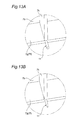
- Figs. 13A to 13C show modifications of the first projection 11.
- a first projection 11 is a columnar member projecting from main ribs 7g and 7f. If the first projection 11 can be inserted into the first gap 12 (see Fig. 11 ) in this manner, it is not necessary that the first projection 11 is tapered.
- a first projection 11 is a thin and long circular truncated cone projecting from main ribs 7g and 7f.
- Fig. 13A shows modifications of the first projection 11.
- a first projection 11 is a columnar member projecting from main ribs 7g and 7f. If the first projection 11 can be inserted into the first gap 12 (see Fig. 11 ) in this manner, it is not necessary that the first projection 11 is tapered.
- a first projection 11 is a thin and long circular truncated cone projecting from main ribs 7g and 7f.
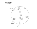
- a first projection 11 is a thin and long circular truncated cone, and the first projection 11 projects not from the main ribs 7g and 7f but from a lower surface of a body 7b of an abutment member 7. If the first projection 11 can be inserted into the first gap 12 (see Fig. 11 ) in this manner, it is not always necessary that the first projection 11 is provided at the main rib 7g or 7f.
- the configurations as shown in Figs. 13A to 13C can be applied to the second gap 15 also.
- positions of the electric cells 2 in the case 4 are held by the partition walls 4c of the case 4, the spacers 5 disposed between the electric cells 2, and the partition ribs 7k having the fixing ribs 7m.
- positions of electric cells 2 in the case 4 are held by the partition walls 4c of the case 4, the spacers 5 disposed between the electric cells 2, and the partition ribs 7k having the fixing ribs 7m.
Landscapes
- Chemical & Material Sciences (AREA)
- Chemical Kinetics & Catalysis (AREA)
- Electrochemistry (AREA)
- General Chemical & Material Sciences (AREA)
- Battery Mounting, Suspending (AREA)
- Sealing Battery Cases Or Jackets (AREA)
Abstract
Description
- The present invention relates to an assembled battery (battery module) including a plurality of electric cells (battery cells) electrically connected to each other so as to be modularized.
- An assembled battery disclosed in each of
JP 2012-128982 A Figs. 9 and10 ) andJP 4638528 B1 Figs. 1 and10 ) includes a case in which a plurality of electric cells are accommodated and an abutment member attached to an upper end opening of the case. The plurality of electric cells abuts against a lower side of the abutment member so as to be positioned in a height direction with respect to the case. - This kind of conventional assembled battery including those disclosed in
JP 2012-128982 A JP 4638528 B1 - However, in the conventional assembled battery including those disclosed in
JP 2012-128982 A JP 4638528 B1 - It is an object of the present invention to enhance attaching operability of an abutment member of the assembled battery including a plurality of electric cells accommodated therein.
- An aspect of the present invention provides an assembled battery comprising, a case in which a plurality of electric cells are accommodated and an abutment member which abuts against the electric cells accommodated in the case to position the electric cells with respect to the case. The abutment member includes a first projection inserted into a first gap defined by the case and the mutually adjacent electric cells to align the abutment member.
-
-
Fig. 1 is an exploded perspective view of an assembled battery according to an embodiment of the present invention; -
Fig. 2 is a perspective view of the assembled battery of the embodiment of the invention (a cover is not illustrated.); -
Fig. 3 is a perspective view of a case; -
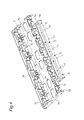
Fig. 4 is a perspective view of an abutment member as viewed from above; -
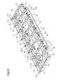
Fig. 5 is a perspective view of the abutment member as viewed from below; -
Fig. 6 is a perspective view of a first projection (with a pedestal) as viewed from below; -
Fig. 7 is a bottom view of the first projection (with a pedestal); -
Fig. 8 is a perspective view of the first projection (without a pedestal) as viewed from below; -
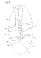
Fig. 9 is a bottom view of the first projection (without a pedestal); -
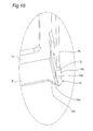
Fig. 10 is a perspective view of a second projection as viewed from below; -
Fig. 11 is a schematic plan view of a first gap into which the first projection (without a pedestal) is inserted; -
Fig. 12 is a schematic plan view of a second gap into which the second projection is inserted; -
Fig. 13A is a perspective view showing a first modification of the first projection; -
Fig. 13B is a perspective view showing a second modification of the first projection; and -
Fig. 13C is a perspective view showing a third modification of the first projection. - An embodiment of the present invention provides an assembled battery comprising, a case in which a plurality of electric cells are accommodated and an abutment member which abuts against the electric cells accommodated in the case to position the electric cells with respect to the case. The abutment member includes a first projection inserted into a first gap defined by the case and the mutually adjacent electric cells to align the abutment member.
- The abutment member is aligned by inserting the first projection into the first gap defined by the electric cells and the case. This enables attachment of the abutment member without precisely aligning thereof. In other words, since the first projection guides the abutment member to the aligned position, the attaching operability of the abutment member is enhanced.
- It is preferable that the first projection is tapered from its proximal end toward its distal end. This achieves easy insertion of the first projection into the first gap, thereby further enhancing the attaching operability of the abutment member.
- It is preferable that the abutment member includes a body which abuts against the electric cells and a rib which projects from the body so as to be inserted into the case, and that a length from the body to a distal end of the first projection is longer than a length from the body to a distal end of the rib. Since the distal end of the first projection projects more than the distal end of the rib, the first projection is reliably inserted into the first gap when the abutment member is attached.
- It is preferable that a gap is provided between the first projection and the rib. When an external force is applied to the first projection due to interference between the first projection and the case or the electric cells at during the attaching operation of the abutment member, the gap allows the first projection itself to deform to some extent independently from the rib. Therefore, by providing the gap, it is possible to prevent the external force applied to the first projection from being transmitted to other portion of the abutment member through the rib.
- Specifically, the case includes a sidewall which surrounds the plurality of electric cells. Further, the rib includes a main rib which projects from the body so as to be inserted between the electric cells and the sidewall. Furthermore, the first projection projects from a distal end of the main rib.
- More specifically, the first projection includes a pair of first inclined surfaces, the distance between the first inclined surfaces in an arraying direction of the mutually adjacent electric cells being gradually reduced from the proximal end toward the distal end.
- As the abutment member approaches the opening of the case, the pair of first inclined surfaces respectively comes into contact with the electric cells. The abutment member is guided by the contact of the first inclined surfaces with the corresponding electric cells so as to be aligned with respect to the opening.
- It is preferable that as viewed from a direction in which the first projection is inserted, the electric cell is provided at its corner portion with an arc portion on a side of the sidewall and a straight portion connected to the arc portion and extending in a direction away from the sidewall. The proximal end of the first projection inserted into the first gap is located closer to the sidewall than a connected portion between the arc portion and the straight portion. By widely setting the maximum width of the first projection, i.e., a distance between the first inclined surfaces in the proximal end, the strength of the first projection can be enhanced. By locating the maximum width portion of the first projection at a position closer to the sidewall than the arc portion and the straight portion, it is unnecessary to excessively largely set a distance between mutually adjacent electric cells.
- The rib may include a partition rib inserted between the mutually adjacent electric cells. In this case, it is preferable that the first projection is provided at a position of the main rib corresponding to an end of the partition rib. Further, in the case of this configuration, it is preferable that the first projection includes a second inclined surface which is provided on an extension line of the partition rib and gradually approaches the main rib from the proximal end toward the distal end. By providing the second inclined surface, the partition rib can is more smoothly inserted between mutually adjacent electrical cells. As a result, since the first projection is more smoothly inserted by the first gap, it is possible to more easily attach the abutment member to the opening of the case.
- The case may include an angle portion formed on a connected portion between the two sidewalls. The abutment member may include a second projection tapered from its proximal end toward its distal end and inserted between a second gap defined by the angle portion and the electric cell so that the abutment member is aligned with respect to the opening of the case.
- The abutment member is aligned by inserting the projection (first projection) provided on the abutment member into the gap (first gap) defined by the electric cells and the case. Therefore, it is possible to attach the abutment member without precisely aligning the abutment member. In other words, since the first projection guides the abutment member to the aligned position, the attaching operability of the abutment member is enhanced.
-
Figs. 1 and2 show an assembled battery (battery module) 1 according to an embodiment of the present invention. The assembledbattery 1 includes eight angle type electric cells (battery cells) 2 which are non-aqueous electrolyte secondary batteries. Each of theelectric cells 2 includes abody 2a (having a flat rectangular parallelepiped shape in this embodiment) in which an electrode assembly and the like are accommodated, and acover 2b which closes an upper end opening of thebody 2a. A pair ofterminals 2c projects from both ends of thecover 2b. The terminal 2c of each of theelectric cells 2 is electrically connected to the terminal 2c of the adjacentelectric cell 2 via abus bar 3. InFig. 1 , the one of twoterminals 2c of theelectric cells 2 located on left and right ends respectively functions as a positive electrode and a negative electrode for the entire assembledbattery 1. - The
electric cells 2 are accommodated in acase 4 made of resin in this embodiment. Referring also toFig. 3 , thecase 4 is of a rectangular parallelepiped as a whole and has a box-shape including anupper end opening 4a. Theelectric cells 2 accommodated in thecase 4 are arrayed in line so that their long sides as viewed from above are opposed to each other. Abottom wall 4b of thecase 4 on which theelectric cells 2 are placed is provided with a plurality of (seven in this embodiment)partition walls 4c which are inserted into bottoms of the mutually adjacent twoelectric cells 2. As shown inFig. 3 in which only one pair of theelectric cells 2 are depicted, aspacer 5 is interposed between the mutually adjacentelectric cells 2. - The
case 4 includessidewalls sidewalls bottom wall 4b. Thesidewalls electric cells 2 as viewed from above. Thecase 4 includessidewalls sidewalls bottom wall 4b. As viewed from above, the sidewalls 4f and 4g are opposed to the long sides of the twoelectric cells 2 located on both ends of the arrayed electric cells 2 (theelectric cells 2 disposed on right and left ends inFig. 1 ). Theupper end opening 4a is defined by upper ends of thesidewalls - An abutment member (intermediate cover) 7 made of resin in this embodiment is attached to the upper end opening 4a of the
case 4 accommodating theelectric cells 2. A cover (outer cover) 8 made of metal in this embodiment is attached to theabutment member 7. Sidewalls of thecover 8 elongated in its long side direction are provided with a plurality of engagingpieces 8a. When thecover 8 is put on theabutment member 7 attached to the upper end opening 4a of thecase 4, the engagingpieces 8a are engaged from inside of the sidewalls with engagingholes 7a provided in theabutment member 7, and thereby theabutment member 7 and thecover 8 are fixed with each other. - Referring also to
Figs. 4 and5 , theabutment member 7 includes abody 7b of substantially rectangular configuration as a whole. In a state where theabutment member 7 is attached to the upper end opening 4a of thecase 4, thebody 7b abuts against top portions of the plurality of (eight in this embodiment)electric cells 2. Throughholes 7c are formed in thebody 7b.Terminals 2c of theelectric cells 2 are respectively exposed from the throughholes 7c. Thebody 7b is provided at its corners withnotches terminals 2c functioning as positive and negative electrodes for the entire assembledbattery 1. - The
abutment member 7 includes two pairs of flat plate-shapedmain ribs 7f to 7i projecting downward from side edges of thebody 7b. One pair ofmain ribs side walls case 4 and pairs of short sides as viewed from above of respectiveelectric cells 2 arrayed in line. The other pair ofmain ribs side walls case 4 and the twoelectric cells 2 located on both ends of the arrayedelectric cells 2 as viewed from above. Themain ribs 7f to 7i are provided with a plurality of engagingprojections 7j. When thecover 8 is attached to the upper end opening 4a of thecase 4, insertion of themain ribs 7f to 7i between thecase 4 and theelectric cells 2 causes the engagingprojections 7j to be fitted into engagingholes 4h formed in thesidewalls 4d to 4g of thecase 4, and thereby theabutment member 7 and thecase 4 are fixed with each other. - As shown in
Fig. 5 , a lower surface of theabutment member 7 is provided with a plurality of (seven in the embodiment) thin and long flat plate-shapedpartition ribs 7k extending from themain rib 7f to themain rib 7g. Each of thepartition ribs 7k is inserted from above between mutually adjacent twoelectric cells 2. Both surfaces of each of thepartition ribs 7k are provided with a plurality of fixingribs 7m which abut against sides of upper ends of theelectric cells 2 when thepartition ribs 7k are inserted between theelectric cells 2. - As most clearly shown in
Fig. 5 , lower ends of themain ribs abutment member 7 are provided with a plurality offirst projections 11. Specifically, thefirst projections 11 are provided at positions where ends of the most left and right side twopartition ribs 7k of the sevenpartition ribs 7k inFig. 5 are connected the ends of themain rib 7g. Further, thefirst projection 11 are provided at positions where both ends of the remaining fivepartition ribs 7k are connected to themain ribs first projections 11 are provided at positions of themain ribs partition ribs 7k. - With reference to
Figs. 6 to 9 , thefirst projections 11 project further downwardly from lower ends of themain ribs body 7b of theabutment member 7 to a distal end of thefirst projection 11 is longer than a length from thebody 7b to distal ends of themain ribs partition ribs 7k. Each of thefirst projections 11 has a shape which is tapered from its upper end (proximal end) connected to themain ribs first projection 11 is inserted from above into afirst gap 12 defined by the upper ends of the mutually adjacentelectric cells 2 and thesidewalls case 4. - Each of the
first projection 11 includes a first isoscelestriangular plate portion 11a located substantially on the same plane with themain rib triangular plate portion 11a configure a pair of firstinclined surfaces inclined surfaces Fig. 11 ) is gradually reduced from the upper end toward the lower end. As shown inFig. 11 , each of the firsttriangular plate portions 11a is inserted into a part of thefirst gap 12, i.e., a gap defined between the mutually adjacentelectric cells 2 and thesidewall case 4. - Each of the
first projections 11 includes a second rectangulartriangular plate portion 11d on the side of an inner surface of the firsttriangular plate portion 11a. One of two sides of the secondtriangular plate portion 11d forming a right angle extends along a symmetric line of the firsttriangular plate portion 11a. A hypotenuse of the secondtriangular plate portion 11d is provided on an extension line of thepartition rib 7k and configures a secondinclined surface 11e which gradually approaches themain ribs Fig. 11 , the secondtriangular plate portion 11d is inserted into other part of thefirst gap 12, i.e., a gap defined by the mutually adjacentelectric cells 2. - As most clearly shown in
Figs. 7 and9 , thefirst projection 11 is provided so that a gap "G" is formed between the firsttriangular plate portion 11a and thepartition rib 7k. As most clearly shown inFigs. 6 and8 , thefirst projection 11 of themain rib 7g is provided at its most proximal end with a substantially trapezoidalcolumnar pedestal 11f, but thefirst projection 11 of themain rib 7f is not provided with a pedestal. - As most clearly shown in
Fig. 5 ,angle portions 7n of theabutment member 7 are formed at connected portions between both ends of themain rib 7g and one ends of themain ribs angle portions 7p are formed at connected portions between both ends of themain rib 7f and thepartition rib 7k. Theangle portions second projections 14. - With reference to
Figs. 10 and12 , thesecond projections 14 project further downward from lower ends of themain ribs second projections 14 is inserted from above into asecond gap 15 defined by theelectric cells 2 and theangle portions - The
second projection 14 includes first and second rectangulartriangular plate portions angle portions triangular plate portions inclined surface - Next, an attaching operation of the
abutment member 7 to thecase 4 will be described. This attaching operation may be carried out manually or by an automatic attaching apparatus. - The attaching operation of the
abutment member 7 to the upper end opening 4a of thecase 4 is carried out after all of the electric cells 2 (eight in this embodiment) are accommodated in thecase 4 and theterminals 2c of the adjacentelectric cells 2 are connected to each other via the bus bars 3. Theabutment member 7 is put on theelectric cells 2 in thecase 4 from above so that themain ribs 7f to 7i of theabutment member 7 are inserted between theelectric cells 2 and thesidewalls 4d to 4g of thecase 4. The engagingprojection 7j of theabutment member 7 is fitted into the engaginghole 4h of thecase 4, and thereby theabutment member 7 is fixed to thecase 4 and the attaching operation is completed. In the attaching operation-completed state, thebody 7b of theabutment member 7 abuts against the top portions of theelectric cells 2 accommodated in thecase 4 so as to determine vertical positions of theelectric cells 2. Theterminals 2c of theelectric cell 2 are exposed upward from thebody 7b through the throughholes 7c (seeFig. 2 ). - Even if the
abutment member 7 descends toward the upper end opening 4a with positional deviation of theabutment member 7 to the upper end opening 4a of thecase 4 as viewed from above, the insertion of the first andsecond projections second gaps abutment member 7 in position as viewed from above with respect to theupper end opening 4a. As a result, themain ribs 7f to 7i of theabutment member 7 are smoothly inserted between thecase 4 and theelectric cells 2. The lengths (projecting amount fromabutment member 7b) of the first andsecond projections main ribs 7f to 7i and thepartition ribs 7k. Further, the first andsecond projections second projections second gaps - The gap "G" is provided between the
first projection 11 and thepartition rib 7k. Therefore, even if an external force is applied to thefirst projection 11 due to interference between thefirst projection 11 and thecase 4 or theelectric cell 2 when theabutment member 7 is attached, the gap "G" allows thefirst projection 11 itself to deform to some extent independently from thepartition rib 7k. Especially, thefirst projection 11 relatively and easily deforms in a direction intersecting with the arraying direction of theelectric cells 2, i.e., in the vertical direction inFigs. 7 and9 . Therefore, providing the gap "G" can prevent the external force applied to thefirst projection 11 from being transmitted to other portions of theabutment member 7 through thepartition rib 7k. - With reference to
Figs. 7 and9 , as viewed from the bottom (in an inserting direction of the first gap 12), each of theelectric cells 2 is provided at its corners witharc portions 2e on the side ofsidewall straight portions 2f connected to thearc portions 2e and extending in a direction way from thesidewall first projection 11 inserted into thefirst gap 12 is located closer to thesidewall arc portions 2e and thestraight portion 2f. Such positional relation between the proximal end of thefirst projection 11 and theelectric cell 2 allows the maximum width of thefirst projection 11, i.e., a distance between the firstinclined surfaces first projection 11 can be enhanced. By locating the maximum width portion of thefirst projection 11 closer to thesidewall arc portion 2e and thestraight portion 2f, it is not necessary to excessively and largely set a distance between the adjacentelectric cells 2. Thearc portion 2e may be of a curved shape not included in an arc shape and may be of a shape composed of a curve and a straight line. - With reference to
Fig. 11 , if a position of theabutment member 7 with respect to the upper end opening 4a of thecase 4 as viewed from above is deviated inward of thecase 4 as shown by an arrow A, the firstinclined surfaces triangular plate portion 11a of thefirst projection 11 abut against anedge 2d (also seeFig. 3 ) which is composed of a connected portion between thebody 7b and the battery cover 8 (also seeFig. 6 ). As theabutment member 7 descends toward the upper end opening 4a of thecase 4, the firstinclined surfaces first projection 11 are guided by theedges 2d of theelectric cells 2, and a position of theabutment member 7 with respect to thecase 4 as viewed from above is displaced so that the positional deviation in the direction of the arrow A is resolved. By this lateral displacement of theabutment member 7, thefirst projection 11 is inserted into thefirst gap 12, the position of theabutment member 7 with respect to thecase 4 as viewed from above is aligned, and themain ribs 7f to 7i of theabutment member 7 are smoothly inserted between thecase 4 and theelectric cells 2 without interfering with theelectric cells 2 or thesidewalls 4d to 4g of thecase 4. Thepartition ribs 7k of theabutment member 7 are inserted into the gaps between the adjacentelectric cells 2. - If the position of the
abutment member 7 with respect to thecase 4 as viewed from above is deviated also in the arraying direction of theelectric cells 2 shown by arrows B1 and B2 in addition to the positional deviation in the direction shown by the arrow A inFig. 11 , not only the firstinclined surfaces triangular plate portion 11a of thefirst projection 11, but also the secondinclined surface 11e of the secondtriangular plate portion 11d abut against theedge 2d of theelectric cell 2. Due to that the firstinclined surfaces inclined surface 11e are guided by theedge 2d of theelectric cell 2, the position of theabutment member 7 with respect to thecase 4 as viewed from above is displaced so that the positional deviations in the directions of the arrows A, B1, and B2 are resolved. By this displacement, themain ribs 7f to 7i of theabutment member 7 are smoothly inserted between thecase 4 and theelectric cells 2 without interfering with theelectric cells 2 and thesidewalls case 4. Thepartition ribs 7k of theabutment member 7 are inserted into the gaps between the adjacentelectric cells 2. The secondtriangular plate portion 11d including the secondinclined surface 11e is provided on the extension line of thepartition rib 7k as described above. Further the secondinclined surface 11e is provided in addition to the firstinclined surfaces triangular plate portion 11a. These arrangements enable thepartition ribs 7k to be more smoothly inserted between the adjacentelectric cells 2. - As described above, since the
first projection 11 is provided, even if the position of theabutment member 7 with respect to the upper end opening 4a of thecase 4 as viewed from above is deviated when theabutment member 7 is attached to the upper end opening 4a of thecase 4, thefirst projection 11 is inserted into thefirst gap 12 so that theabutment member 7 is aligned in position with respect to thecase 4. Therefore, theabutment member 7 is not necessary to be precisely aligned with respect to the upper end opening 4a of thecase 4, enabling easy attachment of theabutment member 7. In other words, since thefirst projection 11 is guided by theedge 2d of theelectric cell 2, theabutment member 7 can be smoothly attached to thecase 4. As a result, the attaching operability of theabutment member 7 with respect to thecase 4 is enhanced. Further, in case that the attaching operation of theabutment member 7 to thecase 4 is carried out by the automatic attaching apparatus, the automatic attaching apparatus is not required to exert excessive aligning precision of theabutment member 7 with respect to thecase 4. - With reference to
Fig. 12 , when the position of theabutment member 7 with respect to the upper end opening 4a of thecase 4 as viewed from above is deviated in the direction shown by the arrow A, theinclined surface 14c of the firsttriangular plate portion 14a of thesecond projection 14 abuts against theedge 2d of theelectric cell 2. Similarly, when the position of theabutment member 7 with respect to the upper end opening 4a of thecase 4 as viewed from above is deviated in the direction shown by the arrow B, theinclined surface 14d of the secondtriangular plate portion 14b of thesecond projection 14 abuts against theedge 2d of theelectric cell 2. Theinclined surfaces triangular plate portions edge 2d of theelectric cell 2. Therefore, as theabutment member 7 descends, the position of theabutment member 7 as viewed from above is displaced in the direction where the positional deviation is resolved. By this lateral displacement of theabutment member 7, thesecond projection 14 is inserted into thesecond gap 15, and thereby the position of theabutment member 7 with respect to thecase 4 as viewed from above is aligned. Therefore, themain ribs 7f to 7i of theabutment member 7 are smoothly inserted between thecase 4 and theelectric cells 2 without interfering with theelectric cells 2 or thesidewalls 4d to 4g of thecase 4. Thepartition ribs 7k of theabutment member 7 are smoothly inserted into gaps between the adjacentelectric cells 2. By providing thesecond projection 14 in addition to thefirst projection 11 in this manner, it is possible to more easily and smoothly attach theabutment member 7 to the upper end opening 4a of thecase 4. -
Figs. 13A to 13C show modifications of thefirst projection 11. In the modification shown inFig. 13A , afirst projection 11 is a columnar member projecting frommain ribs first projection 11 can be inserted into the first gap 12 (seeFig. 11 ) in this manner, it is not necessary that thefirst projection 11 is tapered. In the modification shown inFig. 13B , afirst projection 11 is a thin and long circular truncated cone projecting frommain ribs Fig. 13C , afirst projection 11 is a thin and long circular truncated cone, and thefirst projection 11 projects not from themain ribs body 7b of anabutment member 7. If thefirst projection 11 can be inserted into the first gap 12 (seeFig. 11 ) in this manner, it is not always necessary that thefirst projection 11 is provided at themain rib Figs. 13A to 13C can be applied to thesecond gap 15 also. - The present invention is not limited to the embodiment, and the invention can variously be modified. For example, positions of the
electric cells 2 in thecase 4 are held by thepartition walls 4c of thecase 4, thespacers 5 disposed between theelectric cells 2, and thepartition ribs 7k having the fixingribs 7m. However, as long as the positions ofelectric cells 2 are reliably held, it is possible to employ such a configuration as that one or two of thepartition walls 4c, thespacers 5, and thepartition ribs 7k having the fixingribs 7m are omitted.
Claims (10)
- An assembled battery comprising:a case in which a plurality of electric cells are accommodated; andan abutment member which abuts against the electric cells accommodated in the case to position the electric cells with respect to the case,wherein the abutment member includes a first projection inserted into a first gap defined by the case and the mutually adjacent electric cells to align the abutment member.
- The assembled battery according to claim 1, wherein the first projection is tapered from its proximal end toward its distal end.
- The assembled battery according to claim 1 or 2, wherein the abutment member includes a body which abuts against the electric cells and a rib which projects from the body so as to be inserted into the case,
wherein a length from the body to a distal end of the first projection is longer than a length from the body to a distal end of the rib. - The assembled battery according to claim 3, wherein a gap is provided between the first projection and the rib.
- The assembled battery according to claim 3 or 4, wherein the case includes a sidewall which surrounds the plurality of electric cells,
wherein the rib includes a main rib which projects from the body so as to be inserted between the electric cells and the sidewall, and
wherein the first projection projects from a distal end of the main rib. - The assembled battery according to claim 5, wherein the first projection includes a pair of first inclined surfaces, the distance between the first inclined surfaces in an arraying direction of the mutually adjacent electric cells being gradually reduced from the proximal end toward the distal end.
- The assembled battery according to claim 6, wherein, as viewed from a direction in which the first projection is inserted, the electric cell is provided at its corner portion with an arc portion on a side of the sidewall and a straight portion connected to the arc portion and extending in a direction away from the sidewall, and
wherein the proximal end of the first projection inserted into the first gap is located closer to the sidewall than a connected portion between the arc portion and the straight portion. - The assembled battery according to claim 6 or 7, wherein the rib includes a partition rib inserted between the mutually adjacent electric cells, and
wherein the first projection is provided at a position of the main rib corresponding to an end of the partition rib. - The assembled battery according to claim 8, wherein the first projection includes a second inclined surface which is provided on an extension line of the partition rib and gradually approaches the main rib from the proximal end toward the distal end.
- The assembled battery according to any one of claims 1 to 9, wherein the case includes an angle portion formed on a connected portion between the two sidewalls, and
wherein the abutment member includes a second projection inserted between a second gap defined by the angle portion and the electric cell so that the abutment member is aligned with respect to an opening of the case.
Applications Claiming Priority (1)
| Application Number | Priority Date | Filing Date | Title |
|---|---|---|---|
| JP2012213277A JP6036095B2 (en) | 2012-09-26 | 2012-09-26 | Assembled battery |
Publications (2)
| Publication Number | Publication Date |
|---|---|
| EP2713417A1 true EP2713417A1 (en) | 2014-04-02 |
| EP2713417B1 EP2713417B1 (en) | 2023-11-22 |
Family
ID=49230628
Family Applications (1)
| Application Number | Title | Priority Date | Filing Date |
|---|---|---|---|
| EP13185851.6A Active EP2713417B1 (en) | 2012-09-26 | 2013-09-25 | Assembled battery |
Country Status (5)
| Country | Link |
|---|---|
| US (1) | US9425446B2 (en) |
| EP (1) | EP2713417B1 (en) |
| JP (1) | JP6036095B2 (en) |
| KR (1) | KR102096912B1 (en) |
| CN (1) | CN103682201B (en) |
Cited By (1)
| Publication number | Priority date | Publication date | Assignee | Title |
|---|---|---|---|---|
| CN109659463A (en) * | 2019-01-02 | 2019-04-19 | 南京创源天地动力科技有限公司 | A kind of square power battery group block structure |
Families Citing this family (16)
| Publication number | Priority date | Publication date | Assignee | Title |
|---|---|---|---|---|
| JP5974918B2 (en) * | 2013-02-01 | 2016-08-23 | 株式会社オートネットワーク技術研究所 | Wiring module |
| KR101737489B1 (en) | 2014-06-05 | 2017-05-18 | 주식회사 엘지화학 | Battery pack having improved structure for supporting torque of terminal bolt |
| US10020534B2 (en) | 2014-09-26 | 2018-07-10 | Johnson Controls Technology Company | Free floating battery cell assembly techniques for lithium ion battery module |
| US10103367B2 (en) | 2014-09-26 | 2018-10-16 | Johnson Controls Technology Company | Lithium ion battery module with free floating prismatic battery cells |
| KR101953759B1 (en) * | 2015-09-25 | 2019-03-04 | 주식회사 엘지화학 | Battery module, battery pack comprising the battery module and vehicle comprising the battery pack |
| JP6685760B2 (en) * | 2016-02-19 | 2020-04-22 | 株式会社Gsユアサ | Power storage device |
| JP2018056093A (en) * | 2016-09-30 | 2018-04-05 | 日立オートモティブシステムズ株式会社 | Power storage device |
| CN106784509A (en) * | 2017-03-10 | 2017-05-31 | 江苏索尔新能源科技股份有限公司 | The battery component that a kind of battery core is longitudinally arranged |
| JP2019145459A (en) * | 2018-02-23 | 2019-08-29 | 株式会社東芝 | Battery pack |
| WO2019176560A1 (en) | 2018-03-16 | 2019-09-19 | 株式会社Gsユアサ | Power storage device |
| US11342620B2 (en) * | 2019-03-04 | 2022-05-24 | Chongqing Jinkang Powertrain New Energy Co., Ltd. | Battery module scalable in three dimensions |
| CN110224090A (en) * | 2019-04-24 | 2019-09-10 | 合肥国轩高科动力能源有限公司 | A thermally conductive prismatic battery pack |
| CN210743992U (en) | 2019-10-21 | 2020-06-12 | 宁德时代新能源科技股份有限公司 | Battery modules, battery packs, and devices using battery cells as power sources |
| US12603400B2 (en) | 2019-10-23 | 2026-04-14 | Gs Yuasa International Ltd. | Energy storage apparatus |
| KR102903479B1 (en) * | 2020-04-01 | 2025-12-22 | 삼성에스디아이 주식회사 | Battery pack |
| DE102023119176A1 (en) * | 2023-07-20 | 2025-01-23 | Audi Aktiengesellschaft | side panel for a battery module and battery module |
Citations (4)
| Publication number | Priority date | Publication date | Assignee | Title |
|---|---|---|---|---|
| JP2005150055A (en) * | 2003-11-20 | 2005-06-09 | Sony Corp | Battery tray |
| US20080286640A1 (en) * | 2007-05-16 | 2008-11-20 | Sony Corporation | Battery pack |
| JP4638528B2 (en) | 2008-07-02 | 2011-02-23 | 株式会社Gsユアサ | Assembled battery and assembled battery assembly method |
| JP2012128982A (en) | 2010-12-13 | 2012-07-05 | Lithium Energy Japan:Kk | Battery module |
Family Cites Families (7)
| Publication number | Priority date | Publication date | Assignee | Title |
|---|---|---|---|---|
| KR100560483B1 (en) * | 2004-05-04 | 2006-03-13 | 삼성에스디아이 주식회사 | Secondary battery |
| JP5056155B2 (en) | 2007-05-16 | 2012-10-24 | ソニー株式会社 | Battery pack |
| JP5155772B2 (en) * | 2008-08-19 | 2013-03-06 | 三菱重工業株式会社 | Battery pack structure |
| US20110059365A1 (en) * | 2009-09-09 | 2011-03-10 | Gm Global Technology Operations, Inc. | Process for manufacture and assembly of battery modules and sections |
| JP5644086B2 (en) * | 2009-10-29 | 2014-12-24 | 三洋電機株式会社 | Battery module, power supply device, and vehicle including the same |
| US9263713B2 (en) * | 2010-05-26 | 2016-02-16 | Samsung Sdi Co., Ltd. | Battery pack |
| US20120244397A1 (en) * | 2010-07-12 | 2012-09-27 | Coda Automotive, Inc. | Battery assembly |
-
2012
- 2012-09-26 JP JP2012213277A patent/JP6036095B2/en active Active
-
2013
- 2013-08-21 KR KR1020130099065A patent/KR102096912B1/en active Active
- 2013-09-05 CN CN201310399920.0A patent/CN103682201B/en active Active
- 2013-09-24 US US14/034,655 patent/US9425446B2/en active Active
- 2013-09-25 EP EP13185851.6A patent/EP2713417B1/en active Active
Patent Citations (4)
| Publication number | Priority date | Publication date | Assignee | Title |
|---|---|---|---|---|
| JP2005150055A (en) * | 2003-11-20 | 2005-06-09 | Sony Corp | Battery tray |
| US20080286640A1 (en) * | 2007-05-16 | 2008-11-20 | Sony Corporation | Battery pack |
| JP4638528B2 (en) | 2008-07-02 | 2011-02-23 | 株式会社Gsユアサ | Assembled battery and assembled battery assembly method |
| JP2012128982A (en) | 2010-12-13 | 2012-07-05 | Lithium Energy Japan:Kk | Battery module |
Cited By (1)
| Publication number | Priority date | Publication date | Assignee | Title |
|---|---|---|---|---|
| CN109659463A (en) * | 2019-01-02 | 2019-04-19 | 南京创源天地动力科技有限公司 | A kind of square power battery group block structure |
Also Published As
| Publication number | Publication date |
|---|---|
| CN103682201B (en) | 2018-04-20 |
| CN103682201A (en) | 2014-03-26 |
| JP6036095B2 (en) | 2016-11-30 |
| KR102096912B1 (en) | 2020-04-03 |
| US20140087229A1 (en) | 2014-03-27 |
| US9425446B2 (en) | 2016-08-23 |
| JP2014067648A (en) | 2014-04-17 |
| KR20140040629A (en) | 2014-04-03 |
| EP2713417B1 (en) | 2023-11-22 |
Similar Documents
| Publication | Publication Date | Title |
|---|---|---|
| EP2713417B1 (en) | Assembled battery | |
| US9196984B2 (en) | Substrate connection structure using substrate connector | |
| US8105112B2 (en) | Electrical connector | |
| US10665887B2 (en) | Energy storage apparatus including aligning projection contacting energy storage devices | |
| JP5716857B2 (en) | Battery connector | |
| US9054370B2 (en) | Electric cell and battery assembly | |
| EP2958167A1 (en) | Battery module | |
| US11545717B2 (en) | Energy storage apparatus | |
| EP3187237A1 (en) | Illuminating building block with high light transmission having positioning structure for sheet-shaped electric connection member and method of assembling the same | |
| US10593913B2 (en) | Energy storage apparatus for suppressing adverse effects exerted on circuit boards | |
| US9257687B2 (en) | Battery assembly | |
| JP2015049932A (en) | In-battery wiring module of battery pack | |
| US11978927B2 (en) | Battery module and isolating member | |
| EP3591733A1 (en) | Cover assembly and battery module comprising same | |
| CN104067402A (en) | Terminal fixing structure and power supply device using the terminal fixing structure | |
| KR20140046847A (en) | Battery pack | |
| KR20140064619A (en) | Electric storage device | |
| US11211659B2 (en) | Battery module comprising housing with connector | |
| EP3675298A1 (en) | Electrical connection box | |
| US12300841B2 (en) | Battery module | |
| EP2677605B1 (en) | Electrical connector and electrical connector combination | |
| EP3933960B1 (en) | Secondary battery | |
| JP6962344B2 (en) | Terminal block | |
| JP7719613B2 (en) | Energy storage element unit and building | |
| WO2007013262A1 (en) | Terminal box for solar cell module |
Legal Events
| Date | Code | Title | Description |
|---|---|---|---|
| PUAI | Public reference made under article 153(3) epc to a published international application that has entered the european phase |
Free format text: ORIGINAL CODE: 0009012 |
|
| AK | Designated contracting states |
Kind code of ref document: A1 Designated state(s): AL AT BE BG CH CY CZ DE DK EE ES FI FR GB GR HR HU IE IS IT LI LT LU LV MC MK MT NL NO PL PT RO RS SE SI SK SM TR |
|
| AX | Request for extension of the european patent |
Extension state: BA ME |
|
| 17P | Request for examination filed |
Effective date: 20140925 |
|
| RBV | Designated contracting states (corrected) |
Designated state(s): AL AT BE BG CH CY CZ DE DK EE ES FI FR GB GR HR HU IE IS IT LI LT LU LV MC MK MT NL NO PL PT RO RS SE SI SK SM TR |
|
| RAP1 | Party data changed (applicant data changed or rights of an application transferred) |
Owner name: GS YUASA INTERNATIONAL LTD. |
|
| STAA | Information on the status of an ep patent application or granted ep patent |
Free format text: STATUS: EXAMINATION IS IN PROGRESS |
|
| 17Q | First examination report despatched |
Effective date: 20170410 |
|
| REG | Reference to a national code |
Ref country code: DE Ref legal event code: R079 Free format text: PREVIOUS MAIN CLASS: H01M0002100000 Ipc: H01M0050291000 Ref country code: DE Ref legal event code: R079 Ref document number: 602013084960 Country of ref document: DE Free format text: PREVIOUS MAIN CLASS: H01M0002100000 Ipc: H01M0050291000 |
|
| RIC1 | Information provided on ipc code assigned before grant |
Ipc: H01M 50/267 20210101ALN20230220BHEP Ipc: H01M 50/209 20210101ALI20230220BHEP Ipc: H01M 50/103 20210101ALI20230220BHEP Ipc: H01M 50/271 20210101ALI20230220BHEP Ipc: H01M 50/291 20210101AFI20230220BHEP |
|
| RIC1 | Information provided on ipc code assigned before grant |
Ipc: H01M 50/267 20210101ALN20230321BHEP Ipc: H01M 50/209 20210101ALI20230321BHEP Ipc: H01M 50/103 20210101ALI20230321BHEP Ipc: H01M 50/271 20210101ALI20230321BHEP Ipc: H01M 50/291 20210101AFI20230321BHEP |
|
| GRAP | Despatch of communication of intention to grant a patent |
Free format text: ORIGINAL CODE: EPIDOSNIGR1 |
|
| STAA | Information on the status of an ep patent application or granted ep patent |
Free format text: STATUS: GRANT OF PATENT IS INTENDED |
|
| RIC1 | Information provided on ipc code assigned before grant |
Ipc: H01M 50/267 20210101ALN20230523BHEP Ipc: H01M 50/209 20210101ALI20230523BHEP Ipc: H01M 50/103 20210101ALI20230523BHEP Ipc: H01M 50/271 20210101ALI20230523BHEP Ipc: H01M 50/291 20210101AFI20230523BHEP |
|
| INTG | Intention to grant announced |
Effective date: 20230620 |
|
| P01 | Opt-out of the competence of the unified patent court (upc) registered |
Effective date: 20230721 |
|
| GRAS | Grant fee paid |
Free format text: ORIGINAL CODE: EPIDOSNIGR3 |
|
| GRAA | (expected) grant |
Free format text: ORIGINAL CODE: 0009210 |
|
| STAA | Information on the status of an ep patent application or granted ep patent |
Free format text: STATUS: THE PATENT HAS BEEN GRANTED |
|
| AK | Designated contracting states |
Kind code of ref document: B1 Designated state(s): AL AT BE BG CH CY CZ DE DK EE ES FI FR GB GR HR HU IE IS IT LI LT LU LV MC MK MT NL NO PL PT RO RS SE SI SK SM TR |
|
| REG | Reference to a national code |
Ref country code: GB Ref legal event code: FG4D |
|
| REG | Reference to a national code |
Ref country code: CH Ref legal event code: EP Ref country code: DE Ref legal event code: R096 Ref document number: 602013084960 Country of ref document: DE |
|
| REG | Reference to a national code |
Ref country code: IE Ref legal event code: FG4D |
|
| REG | Reference to a national code |
Ref country code: LT Ref legal event code: MG9D |
|
| REG | Reference to a national code |
Ref country code: NL Ref legal event code: MP Effective date: 20231122 |
|
| PG25 | Lapsed in a contracting state [announced via postgrant information from national office to epo] |
Ref country code: GR Free format text: LAPSE BECAUSE OF FAILURE TO SUBMIT A TRANSLATION OF THE DESCRIPTION OR TO PAY THE FEE WITHIN THE PRESCRIBED TIME-LIMIT Effective date: 20240223 |
|
| PG25 | Lapsed in a contracting state [announced via postgrant information from national office to epo] |
Ref country code: IS Free format text: LAPSE BECAUSE OF FAILURE TO SUBMIT A TRANSLATION OF THE DESCRIPTION OR TO PAY THE FEE WITHIN THE PRESCRIBED TIME-LIMIT Effective date: 20240322 |
|
| PG25 | Lapsed in a contracting state [announced via postgrant information from national office to epo] |
Ref country code: LT Free format text: LAPSE BECAUSE OF FAILURE TO SUBMIT A TRANSLATION OF THE DESCRIPTION OR TO PAY THE FEE WITHIN THE PRESCRIBED TIME-LIMIT Effective date: 20231122 |
|
| REG | Reference to a national code |
Ref country code: AT Ref legal event code: MK05 Ref document number: 1634698 Country of ref document: AT Kind code of ref document: T Effective date: 20231122 |
|
| PG25 | Lapsed in a contracting state [announced via postgrant information from national office to epo] |
Ref country code: NL Free format text: LAPSE BECAUSE OF FAILURE TO SUBMIT A TRANSLATION OF THE DESCRIPTION OR TO PAY THE FEE WITHIN THE PRESCRIBED TIME-LIMIT Effective date: 20231122 |
|
| PG25 | Lapsed in a contracting state [announced via postgrant information from national office to epo] |
Ref country code: AT Free format text: LAPSE BECAUSE OF FAILURE TO SUBMIT A TRANSLATION OF THE DESCRIPTION OR TO PAY THE FEE WITHIN THE PRESCRIBED TIME-LIMIT Effective date: 20231122 |
|
| PG25 | Lapsed in a contracting state [announced via postgrant information from national office to epo] |
Ref country code: ES Free format text: LAPSE BECAUSE OF FAILURE TO SUBMIT A TRANSLATION OF THE DESCRIPTION OR TO PAY THE FEE WITHIN THE PRESCRIBED TIME-LIMIT Effective date: 20231122 |
|
| PG25 | Lapsed in a contracting state [announced via postgrant information from national office to epo] |
Ref country code: NL Free format text: LAPSE BECAUSE OF FAILURE TO SUBMIT A TRANSLATION OF THE DESCRIPTION OR TO PAY THE FEE WITHIN THE PRESCRIBED TIME-LIMIT Effective date: 20231122 Ref country code: LT Free format text: LAPSE BECAUSE OF FAILURE TO SUBMIT A TRANSLATION OF THE DESCRIPTION OR TO PAY THE FEE WITHIN THE PRESCRIBED TIME-LIMIT Effective date: 20231122 Ref country code: IS Free format text: LAPSE BECAUSE OF FAILURE TO SUBMIT A TRANSLATION OF THE DESCRIPTION OR TO PAY THE FEE WITHIN THE PRESCRIBED TIME-LIMIT Effective date: 20240322 Ref country code: GR Free format text: LAPSE BECAUSE OF FAILURE TO SUBMIT A TRANSLATION OF THE DESCRIPTION OR TO PAY THE FEE WITHIN THE PRESCRIBED TIME-LIMIT Effective date: 20240223 Ref country code: ES Free format text: LAPSE BECAUSE OF FAILURE TO SUBMIT A TRANSLATION OF THE DESCRIPTION OR TO PAY THE FEE WITHIN THE PRESCRIBED TIME-LIMIT Effective date: 20231122 Ref country code: BG Free format text: LAPSE BECAUSE OF FAILURE TO SUBMIT A TRANSLATION OF THE DESCRIPTION OR TO PAY THE FEE WITHIN THE PRESCRIBED TIME-LIMIT Effective date: 20240222 Ref country code: AT Free format text: LAPSE BECAUSE OF FAILURE TO SUBMIT A TRANSLATION OF THE DESCRIPTION OR TO PAY THE FEE WITHIN THE PRESCRIBED TIME-LIMIT Effective date: 20231122 Ref country code: PT Free format text: LAPSE BECAUSE OF FAILURE TO SUBMIT A TRANSLATION OF THE DESCRIPTION OR TO PAY THE FEE WITHIN THE PRESCRIBED TIME-LIMIT Effective date: 20240322 |
|
| PG25 | Lapsed in a contracting state [announced via postgrant information from national office to epo] |
Ref country code: SE Free format text: LAPSE BECAUSE OF FAILURE TO SUBMIT A TRANSLATION OF THE DESCRIPTION OR TO PAY THE FEE WITHIN THE PRESCRIBED TIME-LIMIT Effective date: 20231122 Ref country code: RS Free format text: LAPSE BECAUSE OF FAILURE TO SUBMIT A TRANSLATION OF THE DESCRIPTION OR TO PAY THE FEE WITHIN THE PRESCRIBED TIME-LIMIT Effective date: 20231122 Ref country code: PL Free format text: LAPSE BECAUSE OF FAILURE TO SUBMIT A TRANSLATION OF THE DESCRIPTION OR TO PAY THE FEE WITHIN THE PRESCRIBED TIME-LIMIT Effective date: 20231122 Ref country code: NO Free format text: LAPSE BECAUSE OF FAILURE TO SUBMIT A TRANSLATION OF THE DESCRIPTION OR TO PAY THE FEE WITHIN THE PRESCRIBED TIME-LIMIT Effective date: 20240222 Ref country code: LV Free format text: LAPSE BECAUSE OF FAILURE TO SUBMIT A TRANSLATION OF THE DESCRIPTION OR TO PAY THE FEE WITHIN THE PRESCRIBED TIME-LIMIT Effective date: 20231122 Ref country code: HR Free format text: LAPSE BECAUSE OF FAILURE TO SUBMIT A TRANSLATION OF THE DESCRIPTION OR TO PAY THE FEE WITHIN THE PRESCRIBED TIME-LIMIT Effective date: 20231122 |
|
| PG25 | Lapsed in a contracting state [announced via postgrant information from national office to epo] |
Ref country code: DK Free format text: LAPSE BECAUSE OF FAILURE TO SUBMIT A TRANSLATION OF THE DESCRIPTION OR TO PAY THE FEE WITHIN THE PRESCRIBED TIME-LIMIT Effective date: 20231122 |
|
| PG25 | Lapsed in a contracting state [announced via postgrant information from national office to epo] |
Ref country code: CZ Free format text: LAPSE BECAUSE OF FAILURE TO SUBMIT A TRANSLATION OF THE DESCRIPTION OR TO PAY THE FEE WITHIN THE PRESCRIBED TIME-LIMIT Effective date: 20231122 |
|
| PG25 | Lapsed in a contracting state [announced via postgrant information from national office to epo] |
Ref country code: SK Free format text: LAPSE BECAUSE OF FAILURE TO SUBMIT A TRANSLATION OF THE DESCRIPTION OR TO PAY THE FEE WITHIN THE PRESCRIBED TIME-LIMIT Effective date: 20231122 |
|
| PG25 | Lapsed in a contracting state [announced via postgrant information from national office to epo] |
Ref country code: SM Free format text: LAPSE BECAUSE OF FAILURE TO SUBMIT A TRANSLATION OF THE DESCRIPTION OR TO PAY THE FEE WITHIN THE PRESCRIBED TIME-LIMIT Effective date: 20231122 Ref country code: SK Free format text: LAPSE BECAUSE OF FAILURE TO SUBMIT A TRANSLATION OF THE DESCRIPTION OR TO PAY THE FEE WITHIN THE PRESCRIBED TIME-LIMIT Effective date: 20231122 Ref country code: RO Free format text: LAPSE BECAUSE OF FAILURE TO SUBMIT A TRANSLATION OF THE DESCRIPTION OR TO PAY THE FEE WITHIN THE PRESCRIBED TIME-LIMIT Effective date: 20231122 Ref country code: IT Free format text: LAPSE BECAUSE OF FAILURE TO SUBMIT A TRANSLATION OF THE DESCRIPTION OR TO PAY THE FEE WITHIN THE PRESCRIBED TIME-LIMIT Effective date: 20231122 Ref country code: EE Free format text: LAPSE BECAUSE OF FAILURE TO SUBMIT A TRANSLATION OF THE DESCRIPTION OR TO PAY THE FEE WITHIN THE PRESCRIBED TIME-LIMIT Effective date: 20231122 Ref country code: DK Free format text: LAPSE BECAUSE OF FAILURE TO SUBMIT A TRANSLATION OF THE DESCRIPTION OR TO PAY THE FEE WITHIN THE PRESCRIBED TIME-LIMIT Effective date: 20231122 Ref country code: CZ Free format text: LAPSE BECAUSE OF FAILURE TO SUBMIT A TRANSLATION OF THE DESCRIPTION OR TO PAY THE FEE WITHIN THE PRESCRIBED TIME-LIMIT Effective date: 20231122 |
|
| REG | Reference to a national code |
Ref country code: DE Ref legal event code: R097 Ref document number: 602013084960 Country of ref document: DE |
|
| PLBE | No opposition filed within time limit |
Free format text: ORIGINAL CODE: 0009261 |
|
| STAA | Information on the status of an ep patent application or granted ep patent |
Free format text: STATUS: NO OPPOSITION FILED WITHIN TIME LIMIT |
|
| PG25 | Lapsed in a contracting state [announced via postgrant information from national office to epo] |
Ref country code: SI Free format text: LAPSE BECAUSE OF FAILURE TO SUBMIT A TRANSLATION OF THE DESCRIPTION OR TO PAY THE FEE WITHIN THE PRESCRIBED TIME-LIMIT Effective date: 20231122 |
|
| 26N | No opposition filed |
Effective date: 20240823 |
|
| PG25 | Lapsed in a contracting state [announced via postgrant information from national office to epo] |
Ref country code: SI Free format text: LAPSE BECAUSE OF FAILURE TO SUBMIT A TRANSLATION OF THE DESCRIPTION OR TO PAY THE FEE WITHIN THE PRESCRIBED TIME-LIMIT Effective date: 20231122 |
|
| PG25 | Lapsed in a contracting state [announced via postgrant information from national office to epo] |
Ref country code: MC Free format text: LAPSE BECAUSE OF FAILURE TO SUBMIT A TRANSLATION OF THE DESCRIPTION OR TO PAY THE FEE WITHIN THE PRESCRIBED TIME-LIMIT Effective date: 20231122 |
|
| REG | Reference to a national code |
Ref country code: CH Ref legal event code: PL |
|
| PG25 | Lapsed in a contracting state [announced via postgrant information from national office to epo] |
Ref country code: LU Free format text: LAPSE BECAUSE OF NON-PAYMENT OF DUE FEES Effective date: 20240925 |
|
| GBPC | Gb: european patent ceased through non-payment of renewal fee |
Effective date: 20240925 |
|
| PG25 | Lapsed in a contracting state [announced via postgrant information from national office to epo] |
Ref country code: GB Free format text: LAPSE BECAUSE OF NON-PAYMENT OF DUE FEES Effective date: 20240925 |
|
| REG | Reference to a national code |
Ref country code: BE Ref legal event code: MM Effective date: 20240930 |
|
| PG25 | Lapsed in a contracting state [announced via postgrant information from national office to epo] |
Ref country code: BE Free format text: LAPSE BECAUSE OF NON-PAYMENT OF DUE FEES Effective date: 20240930 |
|
| PG25 | Lapsed in a contracting state [announced via postgrant information from national office to epo] |
Ref country code: FR Free format text: LAPSE BECAUSE OF NON-PAYMENT OF DUE FEES Effective date: 20240930 |
|
| PG25 | Lapsed in a contracting state [announced via postgrant information from national office to epo] |
Ref country code: CH Free format text: LAPSE BECAUSE OF NON-PAYMENT OF DUE FEES Effective date: 20240930 |
|
| PG25 | Lapsed in a contracting state [announced via postgrant information from national office to epo] |
Ref country code: IE Free format text: LAPSE BECAUSE OF NON-PAYMENT OF DUE FEES Effective date: 20240925 |
|
| PG25 | Lapsed in a contracting state [announced via postgrant information from national office to epo] |
Ref country code: FI Free format text: LAPSE BECAUSE OF FAILURE TO SUBMIT A TRANSLATION OF THE DESCRIPTION OR TO PAY THE FEE WITHIN THE PRESCRIBED TIME-LIMIT Effective date: 20231122 |
|
| PGFP | Annual fee paid to national office [announced via postgrant information from national office to epo] |
Ref country code: DE Payment date: 20250820 Year of fee payment: 13 |
|
| PG25 | Lapsed in a contracting state [announced via postgrant information from national office to epo] |
Ref country code: CY Free format text: LAPSE BECAUSE OF FAILURE TO SUBMIT A TRANSLATION OF THE DESCRIPTION OR TO PAY THE FEE WITHIN THE PRESCRIBED TIME-LIMIT; INVALID AB INITIO Effective date: 20130925 |
|
| PG25 | Lapsed in a contracting state [announced via postgrant information from national office to epo] |
Ref country code: HU Free format text: LAPSE BECAUSE OF FAILURE TO SUBMIT A TRANSLATION OF THE DESCRIPTION OR TO PAY THE FEE WITHIN THE PRESCRIBED TIME-LIMIT; INVALID AB INITIO Effective date: 20130925 |