EP2713322A1 - Mass reversal of data objects based on reversal tasks and reversal triggers - Google Patents
Mass reversal of data objects based on reversal tasks and reversal triggers Download PDFInfo
- Publication number
- EP2713322A1 EP2713322A1 EP20130186394 EP13186394A EP2713322A1 EP 2713322 A1 EP2713322 A1 EP 2713322A1 EP 20130186394 EP20130186394 EP 20130186394 EP 13186394 A EP13186394 A EP 13186394A EP 2713322 A1 EP2713322 A1 EP 2713322A1
- Authority
- EP
- European Patent Office
- Prior art keywords
- reversal
- task
- data
- data handling
- triggers
- Prior art date
- Legal status (The legal status is an assumption and is not a legal conclusion. Google has not performed a legal analysis and makes no representation as to the accuracy of the status listed.)
- Ceased
Links
Images







Classifications
-
- G—PHYSICS
- G06—COMPUTING OR CALCULATING; COUNTING
- G06Q—INFORMATION AND COMMUNICATION TECHNOLOGY [ICT] SPECIALLY ADAPTED FOR ADMINISTRATIVE, COMMERCIAL, FINANCIAL, MANAGERIAL OR SUPERVISORY PURPOSES; SYSTEMS OR METHODS SPECIALLY ADAPTED FOR ADMINISTRATIVE, COMMERCIAL, FINANCIAL, MANAGERIAL OR SUPERVISORY PURPOSES, NOT OTHERWISE PROVIDED FOR
- G06Q30/00—Commerce
- G06Q30/04—Billing or invoicing
-
- H—ELECTRICITY
- H04—ELECTRIC COMMUNICATION TECHNIQUE
- H04L—TRANSMISSION OF DIGITAL INFORMATION, e.g. TELEGRAPHIC COMMUNICATION
- H04L12/00—Data switching networks
- H04L12/02—Details
- H04L12/14—Charging, metering or billing arrangements specially adapted for data communications, e.g. authentication, authorisation and accounting [AAA] framework
- H04L12/1428—Invoice generation, e.g. customization, lay-out, database processing, algorithms for calculating the bill or formatting invoices as WWW pages
-
- H—ELECTRICITY
- H04—ELECTRIC COMMUNICATION TECHNIQUE
- H04M—TELEPHONIC COMMUNICATION
- H04M15/00—Arrangements for metering, time-control or time indication ; Metering, charging or billing arrangements for voice wireline or wireless communications, e.g. VoIP
- H04M15/44—Augmented, consolidated or itemized billing statement or bill presentation
-
- G—PHYSICS
- G06—COMPUTING OR CALCULATING; COUNTING
- G06Q—INFORMATION AND COMMUNICATION TECHNOLOGY [ICT] SPECIALLY ADAPTED FOR ADMINISTRATIVE, COMMERCIAL, FINANCIAL, MANAGERIAL OR SUPERVISORY PURPOSES; SYSTEMS OR METHODS SPECIALLY ADAPTED FOR ADMINISTRATIVE, COMMERCIAL, FINANCIAL, MANAGERIAL OR SUPERVISORY PURPOSES, NOT OTHERWISE PROVIDED FOR
- G06Q10/00—Administration; Management
- G06Q10/06—Resources, workflows, human or project management; Enterprise or organisation planning; Enterprise or organisation modelling
-
- G—PHYSICS
- G06—COMPUTING OR CALCULATING; COUNTING
- G06Q—INFORMATION AND COMMUNICATION TECHNOLOGY [ICT] SPECIALLY ADAPTED FOR ADMINISTRATIVE, COMMERCIAL, FINANCIAL, MANAGERIAL OR SUPERVISORY PURPOSES; SYSTEMS OR METHODS SPECIALLY ADAPTED FOR ADMINISTRATIVE, COMMERCIAL, FINANCIAL, MANAGERIAL OR SUPERVISORY PURPOSES, NOT OTHERWISE PROVIDED FOR
- G06Q50/00—Information and communication technology [ICT] specially adapted for implementation of business processes of specific business sectors, e.g. utilities or tourism
- G06Q50/60—Business processes related to postal services
-
- H—ELECTRICITY
- H04—ELECTRIC COMMUNICATION TECHNIQUE
- H04L—TRANSMISSION OF DIGITAL INFORMATION, e.g. TELEGRAPHIC COMMUNICATION
- H04L41/00—Arrangements for maintenance, administration or management of data switching networks, e.g. of packet switching networks
- H04L41/22—Arrangements for maintenance, administration or management of data switching networks, e.g. of packet switching networks comprising specially adapted graphical user interfaces [GUI]
-
- H—ELECTRICITY
- H04—ELECTRIC COMMUNICATION TECHNIQUE
- H04M—TELEPHONIC COMMUNICATION
- H04M15/00—Arrangements for metering, time-control or time indication ; Metering, charging or billing arrangements for voice wireline or wireless communications, e.g. VoIP
- H04M15/43—Billing software details
Definitions
- This document generally relates to systems and methods for use in telecommunication systems. More specifically, this document relates to methods and systems for performing a mass reversal of first data objects based on reversal tasks and reversal triggers.
- Telecommunication systems are well-known in prior art. In a variety of applications, it is necessary to cancel or reverse once created data objects. In Addition, in many applications, not only a single data object but a plurality of interconnected data objects has to be reversed. It is an objective of the present invention to provide methods and systems for performing mass reversal of first data objects.
- first/second second data objects within a telecommunication system can be reversed en masse, using reversal tasks and reversal triggers, This allows for an easy reversal of multiple documents. It also allows for a "chain" of documents (i.e., documents that are dependent on other documents to be reversed en masse), even if the user does not explicitly indicate that certain documents in the chain need to be reversed.
- FIG. 1 depicts an application landscape, in accordance with an example embodiment.
- the application landscape 100 comprises different heterogeneous software and/or hardware components 102 to 118, which are connected to each other as shown by the solid lines in FIG. 1 , and which may operate together in the application landscape 100 to process, for example, a telecommunication scenario.
- the application landscape 100 may comprise a central coordination system 102.
- the central coordination system 102 may integrate internal and external management information across an entire organization, embracing different activities and/or services of an enterprise. Central coordination system 102 automates the activities and/or services with an integrated computer-based application.
- a central coordination system 102 can run on a variety of hardware and/or network configurations, typically employing a database to store its data.
- the central coordination system 102 may be associated with (e.g., directly or indirectly connected to and/or in (networked) communication with) a telecommunication intelligence (BI) component 104, one or more third parties 106 and 108, a first management component 110, and/or a second management component 112.
- the second management component 112 and/or the first management component 110 may further be associated with at least one proprietary service 114.
- at least one of the third parties 106 may also be associated with at least one proprietary service 116.
- the telecommunication intelligence component 104 may provide historical, current, and predictive views of telecommunication processes and/or telecommunication scenarios, for example, performed on the central coordination system 102.
- the first management component 110 may manage a network of interconnected processes involved in the provision of product and/or service packages required by end consumers such as the central coordination system 102.
- the first management component 110 may span movement and storage of raw materials, work-in-process inventory, and finished goods from point of origin to point of consumption (also referred to as a supply chain).
- the second management component 112 may specify collaborations with suppliers that are vital to the success of the central coordination system 102 (e.g., to maximize the potential value of those relationships). All of these systems may be integrated via a process integration (PI) component 118.
- PI process integration
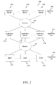
- FIG. 2 is a block diagram of a three tier architecture system, in accordance with an example embodiment.
- the system 200 includes a presentation tier 202, an application tier 204, and a database tier 206.
- Networks 208, 210 connect the devices within and between the tiers.
- the networks 208, 210 may include one or more networks, such as a local area network (LAN), a wide area network (WAN), or the Internet.
- LAN local area network
- WAN wide area network
- the presentation tier 202 generally includes one or more client computers 212.
- the client computers 212 generally provide a graphical user interface for users to interact with the other parts of the system 200,
- the user interface may be implemented by a browser, for example as a Java application.
- the application tier 204 generally includes one or more application servers 214.
- the application servers 214 generally implement the business logic for processing interactions between the users and the underlying data. This business logic is generally referred to as "the application” or "the application program.”
- the application tier 204 may implement various applications to perform various functions, such as invoicing, inventory control, supply chain management, and the like.
- Various of the application servers 214 may perform different functions. For example, one of the application servers 214 may be used for prototyping or development, while the others may be used for business intelligence production activities.
- the database tier 206 generally includes one or more database servers 216.
- the database servers 216 generally implement a database management system that stores and manipulates the underlying data and related metadata. This database management system is generally referred to as "the database,” “the database system,” or “the database program.”
- the database servers 216 may implement various types of database systems, including DB2, Informix, MaxDB, Oracle and Microsoft SQL Server,
- a single database server may be used in the basic configuration, but as the amount of data in the databases increases, the number of database servers 216 may be increased.
- a single application server may be used in the basic configuration, but as the amount of telecommunication logic processes increases, the number of application servers 214 may be increased.
- the various devices in the various tiers may implement different operating systems.
- a client computer 212 may run Microsoft Windows and an application server 214 may implement Linux.
- various devices generally implement both an operating system program and another program, which are distinct.
- a client computer 212 may implement Microsoft Windows (operating system) and Microsoft Internet Explorer (user interface program).
- An application server 214 may implement Linux (operating system) and a data handling system (application program).
- a database server 216 may implement Linux (operating system) and Oracle database (database program).
- the SAP Web Application Server is a specific example of an implementation of the application landscape 100.
- An example embodiment generally involves an application program and a database program, as detailed below.
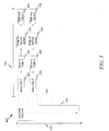
- FIG. 3 is a diagram of a timeline that is used to illustrate an example embodiment of a telecommunication system.
- the timeline 300 includes a y axis 302 and an x axis 304.
- the y axis 302 shows the flow of a generally continuous data generation process where records 310 are generated.
- records generally refers to a line item in a database that includes one or more pieces of data; a record may also be referred to as a "transaction.”
- These records may be (for example) telephone call records, including information such as the calling number, the called number, the start time, the duration, the account number, the applicable tariff, the applicable tax, and the like.
- These records are being continuously generated by the application program (see the application server 214 in FIG.
- "generated” also includes receiving records from other systems.
- Company X may generate a record and send the record to Company Y, in which case Company Y generates a corresponding record in the records 310.
- the number of records in the records 310 may be very large (for example, 1,000,000 customers each receive an invoice with 100 to 1000 calls every month, times the number of months retained in the records 310).
- the records 310 may be stored in a table in a database (see the database server 216 in FIG. 2 and related description).
- the x axis 304 shows the flow of data processing according to an example embodiment of a telecommunication system.
- a set of the records are selected from the records 310.
- the time period may be, for example, a month; and the records selected are those that are to be handled for that month.
- the application program (see the application server 214 in FIG. 2 and related description) may select the set.
- the set is selected as part of another process that may already be occurring as part of the data processing operations of the system 200 (see FIG. 2 ).
- a first data handling process may already be occurring as one of the data processing operations.
- the set selected for invoicing is also the set used in the additional processing described below.
- the set selected in 320 is moved to a table in the database.
- this table includes only the set selected in 320, and no others (e.g., the table excludes the records 310 that are not in the set).
- the application program may instruct the database program (see the database server 216 in FIG. 2 and related description) to move the set to the table in the database.
- the table may include other information related to the records in the set; for example, the set may be indexed according to the account number associated with each record.
- the table (see 322) is stored for a defined duration.
- This duration may be set according to various factors. For example, there may be a legal requirement to store the records for a certain amount of time. There may be a contractual arrangement with the customers to store the records for a certain amount of time.
- the operator of the system 200 may desire to delete records from the database, or to move records from the database to archival storage, after a certain amount of time.
- the operator of the system 200 (see FIG. 2 ) may desire to move or delete the records from the database after the associated invoices have been paid.
- the defined duration may then be selected to account for these time periods, or to account for other criteria.
- the table (see 322) is removed from the database after the defined duration (see 324) has passed.
- the application program (see the application server 214 in FIG. 2 and related description) may instruct the database program (see the database server 216 in FIG. 2 and related description) to remove the table from the database.
- the table may be deleted, moved to archival storage, and so forth. If the database program itself includes functionality to move the table to archival storage, then the application program may instruct the database program to do so. Otherwise, the application program may coordinate with other components of the application landscape 100 (see FIG. 1 ) to move the table from the database to the archival storage.
- the SQL statement DROP TABLE may be used to remove the table.
- a second set of the records are selected from the records 310.
- this time period immediately follows the preceding time period (see 320) without overlap.
- the first time period (see 320) may correspond to January
- the second time period (see 330) may correspond to February.
- the time periods (see 320 and 330) may overlap, in which case there may be duplication of records in the first set and the second set.
- there may be a gap between the first time period and the second time period in which case some of the records 310 may not be selected for moving to a table.
- the second set (selected in 330) is moved to a second table in the database.
- the second table in general, excludes any of the records 310 that are not in the second set.
- the second table (see 332) is stored for a defined duration,
- this defined duration (in 334) has the same length as the first defined duration (in 324).
- the length could also differ.
- the contractual arrangement with customers may be changed such that the duration is shortened (or lengthened).
- the second table (see 332) is removed from the database after the defined duration (see 334) has passed.
- the records in the tables may be further arranged according to the account status (e.g., not processed records, processed records, settled second data objects, etc.).
- these tables may be referred to as "parallel tables” in which the transactional data is divided amongst the tables in a "parallel” manner.
- parallel tables Such an arrangement may be contrasted with existing transactional data processing systems that store the transactional data in a single table (e.g., the data is added to the single table for example in a "sequential" or "serial” manner).
- the telecommunication system may generate a first data object where data from various sources is aggregated into a single document and is processed together.
- the telecommunication system provides the interface to the account receivables system; handles account receivables charges, discounts and taxes; and supports first data object data extraction and formatting for print.
- the telecommunication system may be part of another component, such as a sub-coordinating component that may be part of a larger software system such as a central coordination system (which will be described later in reference to FIG. 4 ).
- the telecommunication system may include a first data handling subcomponent and a second data handling subcomponent.
- the second data subcomponent processes transactions and additional data from other systems and creates structured first data object content.
- Handling first data objects provides a transaction item management feature that allows a user to transfer, store and monitor transaction items and prepare them for first data object execution.
- the second data handling subcomponent covers the handling of transaction items for the purpose of creating, simulating and reversing first data objects.
- the first data handling subcomponent allows a user to create second data objects. It merges information from a local second data handling system, and second data handling systems from other providers, into customer second data objects.
- the first data handling process integrates the first data objects in the first data handling subcomponent.
- the first data handling subcomponent creates the second data object document that saves the information for the second data object and that is the base for the physical second data object printings and posts the second data object synchronously (although in some embodiments this can also be performed asynchronously).
- first data handling subcomponent may perform the following tasks: (1) First data objects from different systems are selected, grouped, and displayed together on one second data object; (2) First data objects are transferred to postings documents in the sub-coordination component synchronously; (3) simultaneously, correspondence containers are created for second data object printing, and additional data is updated for providing data to a telecommunication intelligence system; and (4) current information for the customer account, such as open second data object receivables, can be displayed on the second data object. Further sub-coordination component transactions can be integrated in the second data handling processes such that the customer can be informed of changes to the customer account with the second data object. For example, in an second data handling run, a contract account maintenance can be processed by the run. The second data handling run can clear open items of an second data object with memo items of a contract account.
- second data object orders must exist in order for a second data handling process to be started. These are created when a first data object is created and are used for specific selection of the first data objects not yet processed by an second data handling process. If the data handling of a first data object is successful, the related second data object order is deleted.
- first data objects from the SD component and collective first data objects from the sub-coordination component can also be understood as processable first data objects.
- Special first data handling processes can process these source documents, provided there are second data object orders of the corresponding source document category.
- the first data handling processes use the function of the mass activity in sub-coordination component to split the dataset and distribute processing to different processes in order to reduce the processing time.
- Parallel processing may also be performed during part or all of the process described in FIG. 3 .
- the sub-coordination component is a subledger developed for industries with a large number of partners and a correspondingly high volume of documents to post, such as telecommunications companies.
- This component provides standard accounts receivable and accounts payable functions including dunning, posting documents, and making payments.
- the processes and functions of the sub-coordination component may be integrated with a customer relationship management client, such as the CRM Interaction Center Web Client, by means of a financial customer care component.
- Example CRM functions include the following: (1) financial customer care (this scenario offers basic functions, such as an account overview, the display of the dunning history, and the search for payments of a customer); and (2) collections management (this scenario covers important processes, such as the initiation of customer calls, processing of payments, and the granting of deferrals and installment plans).
- a transaction item is created by a transaction or event and is an item that is to be processed.
- a transaction item can have different statuses at different points in time.
- the system considers only those transaction items that have the status "processable.” Once these items are successfully processed, the system sets their status to "processed.”
- the various statuses of transaction items may be reflected on a technical level using different database tables.
- One exception to this rule is the status "processed.”
- the user can specify how many tables are used, and how they are to be used.
- the system 200 allows the system operator to configure up to 100 parallel tables for transactional use.
- the upload rule specifies that the system does one of the following with transaction items during the transfer: (1) adds them directly to the table of transaction items; (2) adds them to the table for raw data; and (3) returns them as having errors.
- the system may differentiate based on the following record types: (1) main items, which represent the actual receivable or payable; and (2) record types dependent on main items, which represent attachments to the main items (for example, credit card payments or taxation information).
- the main items and the dependent record types may use separate database tables.
- the transaction item class determines the following technical attributes of a transaction item: (1) database tables in which the system saves the transaction items, dependent on their status and on the record type they belong to; (2) function modules that receive the transaction items; (3) function modules that save the transaction items to the appropriate database tables; and (4) specific fields of transaction items that are added either by customer selection of interface components or using customer fields, For each transaction item class, customer-specific checks and data enrichment can be added at various events.
- the interface component represents a process from the viewpoint of data processing.
- the interface component defines which transactions a transaction item class supports (such as deferred revenues and down payment clearings). Interface components are therefore the interface of a transaction item class. From a technical perspective, an interface component consists of the documentation of the component, the selection of needed fields, and the specification of dependent/prerequisite interface components, along with checks, derivations, and assignments of field values.
- a source transaction is defined by the combination of a source transaction type and source transaction identification.
- a source transaction represents a group of transaction items that belong together. According to an embodiment, further processing of transaction items may be controlled by the source transaction (that is, by each combination of a source transaction ID and source transaction type).
- a source transaction can include transaction items belonging to different record types.
- the transaction item type together with the subprocess, specifies the significance of an individual transaction item.
- Each item type is assigned to one or more subprocesses.
- a subprocess is a self-sufficient processing branch within a second data handling process for the selection and grouping of transaction items and forming a first data object.
- transaction items are immediately assigned to a subprocess when they are created. In such an example embodiment, it is not desirable for the system to process them together with transaction items of another subprocess in a common first data object.
- the second data handling process is performed according to defined rules. These rules are defined by parameters used to control the second data handling process.
- the second data handling process specifies which subprocesses it supports. For each subprocess, the second data handling process specifies: (I) which contract accounts are processed; (2) which transaction items are selected for processing; and (3) how the transaction items are grouped into processing units and, as a consequence, how they are grouped into first data objects.
- the selection variant specifies which transaction item class the transaction items are selected from, and therefore also which transaction items are processed in the second data handling process.
- the grouping variant is used for storing the rules for automatic grouping of transaction items for processing.
- the grouping variant determines which transaction items are grouped together in one processing unit and controls the link between the transaction items and the items of the first data object.
- a first data handling process is performed according to defined rules.
- the first data handling process controls: (1) selection of the source documents to be processed; (2) summary of source documents to second data units; and (3) selection of processing functions.
- the system 200 may select and move the records to the tables (see 320 and 322 above) as part of other data processing operations.
- One such data processing operation is the second data handling process.
- second data handling takes place in four individual process steps: data selection, creation of second data units, aggregation of transaction items, and updating.
- the system 200 selects the transaction items
- this selection may also be used as the selection described above at 320.
- the user may define the selection criteria for the data selection in selection variants for the second data handling process.
- the system 200 groups together the selected transaction items into second data units for each contract account. Multiple second data units can be created for each contract account. Second data handling in the sub-coordination component creates one first data object for each billing unit. The user may define the criteria that are used to create the second data units in grouping variants for the second data handling process.
- the system 200 includes the selected transaction items of a second data unit in the first data object. More exactly, the transaction items are summarized in first data object items. The individual items that belong to this summarization are linked with the first data object item.
- the system 200 writes the first data object created for the second data handling unit and the individual processed items to the database, and at the same time deletes the processed transaction items.
- FIG. 4 is an architecture diagram illustrating a convergent invoicing system within an central coordination system, in accordance with an example embodiment.
- Telecommunication system 400 may be run within a sub-coordination system 402 within an central coordination system 404.
- the telecommunication system 400 may include a second data handling component 406 and a first data handling component 408.
- the second data handling component 406 may include a transaction item (BIT) management component 410, a second data handling process 412, and transaction items 414.
- the transaction items 414 as described earlier, may be stored in a database.
- the BIT management component 410 may interface with a convergent charging (CC) component 410.
- the CC component 416 has the ability to control services and manage balances in real-time.
- CC convergent charging
- the BIT management component 410 may also interface with a Customer Relationship Management (CRM) system 424 and, specifically, the one-off order management component 426 of the CRM system 424.
- CRM Customer Relationship Management
- the first data handling component 408 may include an first data handling process 428, as well as a data record, which includes at least one second data object 432, at least one second data object order 434, and at least one first data object 436.
- the first data handling process 428 may coordinate with a database 438 to post documents 440 and generate the data record, as well as coordinate with an external processing system 442 to actually send out bills.
- the first data handling process 428 also interfaces with first data objects 444 generated by a sales and distribution component 446.
- first and second data objects When an error is found in one of the first and second data objects, it may be necessary for a user to initiate a reversal of the document. Of course, reversal can also occur for reasons other than an error (such as a discount, law change (for example, a change in a tax rate), or implementation of new rules). Nevertheless, currently, such reversals must be performed manually. Specifically, the user must first identify all the documents that contain an error. Then each of the document numbers for these documents must be individually specified in a user interface. These documents must then be reversed immediately.
- the determination of the documents to be reversed and the execution of the reversal task are decoupled. This makes it possible to follow a "4-eye principle," whereby at least one other person reviews the reversal plan prior to being executed.
- the user establishes a reversal task.
- the reversal task points to one or more reversal triggers, which each define a reversal that is to occur to a single document in the system.
- the reversal task embraces the multiple corrections that need to be performed in the system, both to transaction items 414 and data records 430.
- An example of a reversal task applying to both transaction items 414 and data records 430 is the case of reversing a charge for an Internet download. It would not be enough simply to reverse the change to the user's account (in data records 430); it is also necessary to reverse the authorization for the download to occur as the transaction item 414 will be assigned to the wrong user account.
- the system can also automatically add additional reversal triggers for additional documents to a reversal task.
- the user may specify that the reversal task contains reversal triggers for documents 1-10.
- the system may know, however, that document 3 is linked to document 11. In such cases, the system will automatically add reversal triggers for these additional documents (document 11 in this example) to the task, even though the user has not expressly requested as much.
- the system can also cause the rerating of transaction items 414 or data records 430. Rerating occurs when it is necessary for the CC component 416 to resend the data used to create the transaction item 414 or data records 430.
- the system augments the reversal task to include instructions to the CC component 416 to do just that, if necessary.
- FIG. 5 is a block diagram illustrating a reversal task, in accordance with an example embodiment.
- the reversal task 500 is linked to a number of classes of reversal tasks 502a-502c.
- Each class of reversal tasks 502a-502c corresponds to a different type of reversal task. Depicted here are a first data object reversal task 502a, an second data object reversal task 502b, and an "other" reversal task 502c.
- These classes of reversal tasks 502a-502c provide for a field for a reason of reversal to be identified.
- Each of these classes of reversal tasks 502a-502c may be linked to one or more reversal triggers 504a-504e, each corresponding to a first data object 506a-506e.
- First data objects 506a-506b may be located in the second data handling component 406 and second data objects 506c-506d may be located in the first data handling component 408.
- Other first data objects 506e may be located in other modules.
- the corresponding reversal triggers can be deleted.
- the system may leave the reversal task in place in case the user wishes to add future reversal triggers to the reversal task.
- a reversal trigger can exist without a linked reversal task. Such independent triggers can simply be executed and deleted.
- FIG. 6 is a diagram illustrating a reversal task administrative record, in accordance with an example embodiment. As can be seen, this record includes a number of fields. Most importantly, the record 600 includes a description 602 of the reversal task and a status 604 of the reversal task. The possible states for the status 604 include open (cannot be processed yet. i.e., still a work-in-progress), released, aborted, finished, and rejected. Other states may be possible in various implementations.
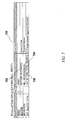
- FIG. 7 is a diagram illustrating a reversal task billing record, in accordance with an example embodiment.
- this record includes a number of fields.
- the record 700 includes an identification 702 of a corresponding reversal task and a reason for reversal 704.
- the record 700 may also contain a total 706 of the number of reversal triggers corresponding to this reverse task billing record 700. This can be useful in resource planning for the eventual execution of the reversal triggers.
- FIG. 8 is a diagram illustrating a reversal task invoicing record, in accordance with an example embodiment.
- this record includes a number of fields, Most importantly, the record 800 includes an identification 802 of a corresponding reversal task and a reason for reversal 804.
- the record 800 may also contain a total 806 of the number of reversal triggers corresponding to this reverse task invoicing record 800. This can be useful in resource planning for the eventual execution of the reversal triggers.
- FIG. 9 is a diagram illustrating a billing reversal trigger record, in accordance with an example embodiment.
- this record includes a number of fields.
- the record 900 includes a first data object number 902, which uniquely identifies the first data object corresponding to this reversal trigger.
- the record 900 also includes an identification 904 of the reversal task to which this reversal trigger corresponds.
- FIG. 10 is a diagram illustrating an invoicing reversal trigger record, in accordance with an example embodiment.
- this record includes a number of fields.
- the record 1000 includes a number 1002, which uniquely identifies the second data object corresponding to this reversal trigger.
- the record 1000 also includes an identification 1004 of the reversal task to which this reversal trigger corresponds.
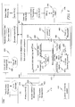
- FIG. 11 is a diagram illustrating a process flow for operating a reversal task, in accordance with an example embodiment.
- the reversal task is created. This reversal task is then depicted as 1102. Once this task is created, reversal triggers can be added or removed at 1104. This may continue to loop until the reversal task is released at 1106 or revoked at 1108. While releasing the reversal task is depicted as being performed by an agent, in reality a different entity may perform the releasing than created the task/triggers. In one example embodiment, while a user may create the task and triggers, a supervisor actually performs the releasing of the reversal tasks.
- the reversal task may be processed at 1110. This may involve processing all the reversal triggers in the reversal task. At 1112, it is determined if the process has completed. If so, then at 1114 the reversal task is complete. At any point, the user can cancel the reversal task at 1116, which also ends the process.
- FIG, 12 is a flow diagram illustrating a method of reversing documents in a telecommunication system, in accordance with an example embodiment.
- a first set of one or more reversal triggers is received, wherein each of the one or more task triggers corresponds to a first and/ or second data object in the telecommunication system. It should be noted that even though this act is described as receiving a set, the individual reversal triggers in the set can, in one example embodiment, be received one at a time. There is no necessity that they all be received at the same time.
- a reversal task is received, wherein the reversal task corresponds to the first set of one or more reversal triggers.
- a second set of reversal triggers is automatically corresponded to the reversal task, based upon documents corresponding to the one or more task triggers in the first set of one or more reversal triggers.
- an indication that the reversal task has been released is received, It should be noted that 1200, 1202, and 1206 all describe acts where items are received. These items can be received by different users for different steps. For example, a first user can provide the items in 1200 and 1202 and a second user, perhaps the first user's supervisor, can provide the indication in 1206,
- a loop may be started for each reversal trigger corresponding to the reversal task.
- the reversal trigger is processed, causing a corresponding document to be reversed.
- the reversal trigger can be deleted.
- FIG. 13 is an interaction diagram illustrating a method of reversing documents in a telecommunication system, in accordance with an example embodiment.
- Components in this diagram include a first user 1300, a second user 1302, a second data handling process 1304, a database 1306, and a CC component 1308.
- the first user 1300 creates reversal triggers for a first set of reversal triggers. These are created in the second data handling process 1304.
- the first user 1300 creates a reversal task correlated with the first set of reversal triggers. Again these are created in the second data handling process 1304.
- the second data handling process 1304 automatically correlates a second set of reversal triggers with the reversal task.
- the reversal task is sent to a second user 1302 for approval.
- This second user may be, for example, a supervisor.
- the second user 1302 releases the reversal task.
- the second data handling process 1304 processes the reversal task 1320. This may involve reversing documents at 1322 as per the reversal task (more particularly as per the reversal triggers in the reversal task), or rerating consumption records in the CC component 1308 at 1324.
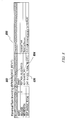
- FIGS. 14-16 are diagrams depicting screen captures in accordance with an example embodiment.
- a screen 1400 is presented where a user can create a reversal task, including an identification 1402 of the task, a name 1404 for the task, as well as selecting whether first data objects 1406 and/or second data objects 1408 are to be reversed, and reversal reasons 1410, 1412 for each.
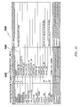
- a screen 1500 is presented including a window 1502 for entering first data objects, when the user selects on an "add first data objects" button 1504.
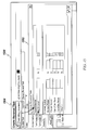
- the first data objects may show up in a first data object list 1600 depicted in FIG. 16 .
- FIG. 17 is a block diagram of a computer processing system at a server system, within which a set of instructions, for causing the computer to perform any one or more of the methodologies discussed herein, may be executed.
- Embodiments may also, for example, be deployed by Software-as-a-Service (SaaS), Application Service Provider (ASP), or utility computing providers, in addition to being sold or licensed via traditional channels.
- the computer may be a server computer, a personal computer (PC), a tablet PC, a set-top box (STB), a personal digital assistant (PDA), cellular telephone, or any processing device capable of executing a set of instructions (sequential or otherwise) that specify actions to be taken by that device.
- PC personal computer
- PDA personal digital assistant
- cellular telephone or any processing device capable of executing a set of instructions (sequential or otherwise) that specify actions to be taken by that device.
- the term "computer” shall also be taken to include any collection of computers that individually or jointly execute a set (or multiple sets) of instructions to perform any one or more of the methodologies discussed herein.
- the example computer processing system 1700 includes processor 1702 (e.g., a central processing unit (CPU), a graphics processing unit (GPU) or both), main memory 1704 and static memory 1706, which communicate with each other via bus 1708.
- the processing system 1700 may further include graphics display unit 1710 (e.g., a plasma display, a liquid crystal display (LCD), or a cathode ray tube (CRT)).
- graphics display unit 1710 e.g., a plasma display, a liquid crystal display (LCD), or a cathode ray tube (CRT)
- the processing system 1700 also includes alphanumeric input device 1712 (e.g., a keyboard), a cursor control device (U1) navigation device 1714 (e.g., a mouse, touch screen, or the like), a disk drive unit 1716, a signal generation device 1718 (e.g., a speaker), and a network interface device 1720.
- alphanumeric input device 1712 e.g., a keyboard
- cursor control device (U1) navigation device 1714 e.g., a mouse, touch screen, or the like
- disk drive unit 1716 e.g., a disk drive unit 1716
- signal generation device 1718 e.g., a speaker
- the disk drive unit 1716 includes computer-readable medium 1722 on which is stored one or more sets of instructions and data structures (e.g.. software 1724) embodying or utilized by any one or more of the methodologies or functions described herein.
- the software 1724 may also reside, completely or at least partially, within the main memory 1704 and/or within the processor 1702 during execution thereof by the processing system 1700, with the main memory 1704 and the processor 1702 also constituting computer-readable, tangible media.
- the software 1724 may further be transmitted or received over network 1726 via a network interface device 1720 utilizing any one of a number of well-known transfer protocols (e.g., Hypertext Transfer Protocol (HTTP)).
- HTTP Hypertext Transfer Protocol
- While the computer-readable medium 1722 is shown in an example embodiment to be a single medium, the term “computer-readable medium” should be taken to include a single medium or multiple media (e.g., a centralized or distributed database, and/or associated caches and servers) that store the one or more sets of instructions.
- the term “computer-readable medium” shall also be taken to include any medium that is capable of storing, encoding or carrying a set of instructions for execution by the computer and that cause the computer to perform any one or more of the methodologies of the present application, or that is capable of storing, encoding or carrying data structures utilized by or associated with such a set of instructions.
- the term “computer-readable medium” shall accordingly be taken to include, but not be limited to, solidstate memories, and optical and magnetic media.
- computer readable medium is used generally to refer to media such as main memory, secondary memory, removable storage, hard disks, flash memory, disk drive memory, CD-ROM and other forms of persistent memory.
- program storage devices as may be used to describe storage devices containing executable computer code for operating various methods, shall not be construed to cover transitory subject matter, such as carrier waves or signals.
- Program storage devices and computer readable medium are terms used generally to refer to media such as main memory, secondary memory, removable storage disks, hard disk drives, and other tangible storage devices or components.
Landscapes
- Engineering & Computer Science (AREA)
- Business, Economics & Management (AREA)
- Computer Networks & Wireless Communication (AREA)
- Signal Processing (AREA)
- Development Economics (AREA)
- Marketing (AREA)
- Economics (AREA)
- Finance (AREA)
- Accounting & Taxation (AREA)
- Strategic Management (AREA)
- Physics & Mathematics (AREA)
- General Business, Economics & Management (AREA)
- General Physics & Mathematics (AREA)
- Theoretical Computer Science (AREA)
- Databases & Information Systems (AREA)
- Management, Administration, Business Operations System, And Electronic Commerce (AREA)
- Information Retrieval, Db Structures And Fs Structures Therefor (AREA)
Abstract
receiving a first set of one or more reversal triggers by the second data handling component, wherein each of the one or more reversal triggers corresponds to a first data object in the telecommunication system;
receiving a reversal task by the second data handling component, wherein the reversal task corresponds to the first set of one or more reversal triggers:
automatically corresponding a second set of reversal triggers to the reversal task by the second data handling component , based upon first data objects corresponding to the one or more task triggers in the first set of one or more reversal triggers;
receiving an indication by the second data handling component that the re-versal task has been refeased;
in response to the indication that the reversal task has been released, for each reversal trigger corresponding to the reversal task:
processing the reversal trigger by the second data handling component, causing a corresponding first data object to be reversed in the data-base; and
deleting the reversal trigger.
Description
- This document generally relates to systems and methods for use in telecommunication systems. More specifically, this document relates to methods and systems for performing a mass reversal of first data objects based on reversal tasks and reversal triggers.
- Telecommunication systems are well-known in prior art. In a variety of applications, it is necessary to cancel or reverse once created data objects. In Addition, in many applications, not only a single data object but a plurality of interconnected data objects has to be reversed. It is an objective of the present invention to provide methods and systems for performing mass reversal of first data objects.
- The present disclosure is illustrated by way of example and not limitation in the figures of the accompanying drawings, in which like references indicate similar elements and in which:
-
FIG. 1 depicts an application landscape, in accordance with an example embodiment. -
FIG. 2 is a block diagram of a three tier architecture system, in accordance with an example embodiment. -
FIG. 3 is a diagram of a timeline that is used to illustrate an example embodiment of a telecommunication system, -
FIG. 4 is an architecture diagram illustrating a convergent invoicing system within an FRP, in accordance with an example embodiment, -
FIG. 5 is a block diagram illustrating a reversal task, in accordance with an example embodiment, -
FIG. 6 is a diagram illustrating a reversal task administrative record, in accordance with an example embodiment. -
FIG, 7 is a diagram illustrating a reversal task billing record, in accordance with an example embodiment. -
FIG. 8 is a diagram illustrating a reversal task invoicing record, in accordance with an example embodiment, -
FIG. 9 is a diagram illustrating a billing reversal trigger record, in accordance with an example embodiment. -
FIG. 10 is a diagram illustrating an invoicing reversal trigger record, in accordance with an example embodiment. -
FIG. 11 is a diagram illustrating a process flow for operating a reversal task, in accordance with an example embodiment. -
FIG. 12 is a flow diagram illustrating a method of reversing documents in a telecommunication system, in accordance with an example embodiment. -
FIG. 13 is an interaction diagram illustrating a method of reversing documents in a telecommunication system, in accordance with an example embodiment. -
FIG. 14 is a diagram illustrating a screen capture of a reversal task creation screen in accordance with an example embodiment. -
FIG. 15 is a diagram illustrating a screen capture of a billing document entry screen in accordance with an example embodiment. -
FIG. 16 is a diagram illustrating a screen capture of a document list for a reversal task in accordance with an example embodiment. -
FIG. 17 is a block diagram of a computer processing system at a server system, within which a set of instructions, for causing the computer to perform any one or more of the methodologies discussed herein, may be executed. - The description that follows includes illustrative systems, methods, techniques, instruction sequences, and computing machine program products that embody illustrative embodiments. In the following description, for purposes of explanation, numerous specific details are set forth in order to provide an understanding of various embodiments of the inventive subject matter. It will be evident, however, to those skilled in the art that embodiments of the inventive subject matter may be practiced without these specific details. In general, well-known instruction instances, protocols, structures, and techniques have not been shown in detail.
- In an example embodiment, first/second second data objects within a telecommunication system can be reversed en masse, using reversal tasks and reversal triggers, This allows for an easy reversal of multiple documents. It also allows for a "chain" of documents (i.e., documents that are dependent on other documents to be reversed en masse), even if the user does not explicitly indicate that certain documents in the chain need to be reversed.
-
FIG. 1 depicts an application landscape, in accordance with an example embodiment. Theapplication landscape 100 comprises different heterogeneous software and/orhardware components 102 to 118, which are connected to each other as shown by the solid lines inFIG. 1 , and which may operate together in theapplication landscape 100 to process, for example, a telecommunication scenario. Theapplication landscape 100 may comprise acentral coordination system 102. Thecentral coordination system 102 may integrate internal and external management information across an entire organization, embracing different activities and/or services of an enterprise.Central coordination system 102 automates the activities and/or services with an integrated computer-based application. Acentral coordination system 102 can run on a variety of hardware and/or network configurations, typically employing a database to store its data. Thecentral coordination system 102 may be associated with (e.g., directly or indirectly connected to and/or in (networked) communication with) a telecommunication intelligence (BI)component 104, one or morethird parties first management component 110, and/or asecond management component 112. Thesecond management component 112 and/or thefirst management component 110 may further be associated with at least oneproprietary service 114. Furthermore, at least one of thethird parties 106 may also be associated with at least oneproprietary service 116. Thetelecommunication intelligence component 104 may provide historical, current, and predictive views of telecommunication processes and/or telecommunication scenarios, for example, performed on thecentral coordination system 102. Common functionality of telecommunication intelligence technologies may comprise reporting, online analytical processing, analytics, data mining, telecommunication performance management, benchmarking, text mining, and/or predictive analytics. The functionality may be used to support better decision making in thecentral coordination system 102. Thefirst management component 110 may manage a network of interconnected processes involved in the provision of product and/or service packages required by end consumers such as thecentral coordination system 102. Thefirst management component 110 may span movement and storage of raw materials, work-in-process inventory, and finished goods from point of origin to point of consumption (also referred to as a supply chain). Thesecond management component 112 may specify collaborations with suppliers that are vital to the success of the central coordination system 102 (e.g., to maximize the potential value of those relationships). All of these systems may be integrated via a process integration (PI)component 118. -
FIG. 2 is a block diagram of a three tier architecture system, in accordance with an example embodiment. Thesystem 200 includes apresentation tier 202, anapplication tier 204, and adatabase tier 206.Networks networks - The
presentation tier 202 generally includes one ormore client computers 212. Theclient computers 212 generally provide a graphical user interface for users to interact with the other parts of thesystem 200, The user interface may be implemented by a browser, for example as a Java application. - The
application tier 204 generally includes one ormore application servers 214. Theapplication servers 214 generally implement the business logic for processing interactions between the users and the underlying data. This business logic is generally referred to as "the application" or "the application program." Theapplication tier 204 may implement various applications to perform various functions, such as invoicing, inventory control, supply chain management, and the like. Various of theapplication servers 214 may perform different functions. For example, one of theapplication servers 214 may be used for prototyping or development, while the others may be used for business intelligence production activities. - The
database tier 206 generally includes one ormore database servers 216. Thedatabase servers 216 generally implement a database management system that stores and manipulates the underlying data and related metadata. This database management system is generally referred to as "the database," "the database system," or "the database program." Thedatabase servers 216 may implement various types of database systems, including DB2, Informix, MaxDB, Oracle and Microsoft SQL Server, - Although many separate devices are shown in each tier, this is mainly for illustration purposes to show scalability, For example, a single database server may be used in the basic configuration, but as the amount of data in the databases increases, the number of
database servers 216 may be increased. As another example, a single application server may be used in the basic configuration, but as the amount of telecommunication logic processes increases, the number ofapplication servers 214 may be increased. - The various devices in the various tiers may implement different operating systems. For example, a
client computer 212 may run Microsoft Windows and anapplication server 214 may implement Linux. Note that various devices generally implement both an operating system program and another program, which are distinct. For example, aclient computer 212 may implement Microsoft Windows (operating system) and Microsoft Internet Explorer (user interface program). Anapplication server 214 may implement Linux (operating system) and a data handling system (application program). Adatabase server 216 may implement Linux (operating system) and Oracle database (database program). - The SAP Web Application Server is a specific example of an implementation of the
application landscape 100. An example embodiment generally involves an application program and a database program, as detailed below. -
FIG. 3 is a diagram of a timeline that is used to illustrate an example embodiment of a telecommunication system. Thetimeline 300 includesa y axis 302 and anx axis 304. They axis 302 shows the flow of a generally continuous data generation process whererecords 310 are generated. (The term "record" generally refers to a line item in a database that includes one or more pieces of data; a record may also be referred to as a "transaction.") These records may be (for example) telephone call records, including information such as the calling number, the called number, the start time, the duration, the account number, the applicable tariff, the applicable tax, and the like. These records are being continuously generated by the application program (see theapplication server 214 inFIG. 2 and related description). In the context of a telecommunication system, "generated" also includes receiving records from other systems. For example, Company X may generate a record and send the record to Company Y, in which case Company Y generates a corresponding record in therecords 310. The number of records in therecords 310 may be very large (for example, 1,000,000 customers each receive an invoice with 100 to 1000 calls every month, times the number of months retained in the records 310). Therecords 310 may be stored in a table in a database (see thedatabase server 216 inFIG. 2 and related description). - The
x axis 304 shows the flow of data processing according to an example embodiment of a telecommunication system. At 320, for a given time period, a set of the records are selected from therecords 310. The time period may be, for example, a month; and the records selected are those that are to be handled for that month. The application program (see theapplication server 214 inFIG. 2 and related description) may select the set. - In an example embodiment, the set is selected as part of another process that may already be occurring as part of the data processing operations of the system 200 (see
FIG. 2 ). For example, a first data handling process may already be occurring as one of the data processing operations. In such a case, the set selected for invoicing is also the set used in the additional processing described below. - At 322, the set selected in 320 is moved to a table in the database.
- In general, this table includes only the set selected in 320, and no others (e.g., the table excludes the
records 310 that are not in the set). The application program (see theapplication server 214 inFIG. 2 and related description) may instruct the database program (see thedatabase server 216 inFIG. 2 and related description) to move the set to the table in the database. The table may include other information related to the records in the set; for example, the set may be indexed according to the account number associated with each record. - At 324, the table (see 322) is stored for a defined duration. This duration may be set according to various factors. For example, there may be a legal requirement to store the records for a certain amount of time. There may be a contractual arrangement with the customers to store the records for a certain amount of time. The operator of the system 200 (see
FIG. 2 ) may desire to delete records from the database, or to move records from the database to archival storage, after a certain amount of time. The operator of the system 200 (seeFIG. 2 ) may desire to move or delete the records from the database after the associated invoices have been paid. The defined duration may then be selected to account for these time periods, or to account for other criteria. - At 326, the table (see 322) is removed from the database after the defined duration (see 324) has passed. The application program (see the
application server 214 inFIG. 2 and related description) may instruct the database program (see thedatabase server 216 inFIG. 2 and related description) to remove the table from the database. The table may be deleted, moved to archival storage, and so forth. If the database program itself includes functionality to move the table to archival storage, then the application program may instruct the database program to do so. Otherwise, the application program may coordinate with other components of the application landscape 100 (seeFIG. 1 ) to move the table from the database to the archival storage. According to an embodiment, the SQL statement DROP TABLE may be used to remove the table. - As the
records 310 continue to be generated, other sets may be selected, moved, and removed in a similar manner to that described above (see 320, 322, 324 and 326), as further detailed below. - At 330, for another given time period, a second set of the records are selected from the
records 310. In general, this time period immediately follows the preceding time period (see 320) without overlap. For example, if second data objects are prepared monthly, then the first time period (see 320) may correspond to January, and the second time period (see 330) may correspond to February. In such a case, there is no duplication of a record in the first set and the second set. According to another example embodiment, the time periods (see 320 and 330) may overlap, in which case there may be duplication of records in the first set and the second set. According to another example embodiment, there may be a gap between the first time period and the second time period, in which case some of therecords 310 may not be selected for moving to a table. - At 332, the second set (selected in 330) is moved to a second table in the database. As with the first table (see 322), the second table, in general, excludes any of the
records 310 that are not in the second set. - At 334, the second table (see 332) is stored for a defined duration, In general, this defined duration (in 334) has the same length as the first defined duration (in 324). However, the length could also differ. For example, the contractual arrangement with customers may be changed such that the duration is shortened (or lengthened).
- At 336, the second table (see 332) is removed from the database after the defined duration (see 334) has passed.
- In a similar manner, additional sets of data beyond the two shown and described may be selected, moved to tables, and the tables removed, as the
records 310 continue to be generated. According to an example embodiment, the records in the tables may be further arranged according to the account status (e.g., not processed records, processed records, settled second data objects, etc.). In general, these tables may be referred to as "parallel tables" in which the transactional data is divided amongst the tables in a "parallel" manner. Such an arrangement may be contrasted with existing transactional data processing systems that store the transactional data in a single table (e.g., the data is added to the single table for example in a "sequential" or "serial" manner). - The following discussion provides more details of a specific implementation of a telecommunication system that implements one or more of the data processing features that were described above. The telecommunication system may generate a first data object where data from various sources is aggregated into a single document and is processed together. In general, the telecommunication system provides the interface to the account receivables system; handles account receivables charges, discounts and taxes; and supports first data object data extraction and formatting for print. The telecommunication system may be part of another component, such as a sub-coordinating component that may be part of a larger software system such as a central coordination system (which will be described later in reference to
FIG. 4 ). The telecommunication system may include a first data handling subcomponent and a second data handling subcomponent. - The second data subcomponent processes transactions and additional data from other systems and creates structured first data object content. Handling first data objects provides a transaction item management feature that allows a user to transfer, store and monitor transaction items and prepare them for first data object execution. The second data handling subcomponent covers the handling of transaction items for the purpose of creating, simulating and reversing first data objects.
- The first data handling subcomponent allows a user to create second data objects. It merges information from a local second data handling system, and second data handling systems from other providers, into customer second data objects. The first data handling process integrates the first data objects in the first data handling subcomponent. The first data handling subcomponent creates the second data object document that saves the information for the second data object and that is the base for the physical second data object printings and posts the second data object synchronously (although in some embodiments this can also be performed asynchronously). Additionally the first data handling subcomponent may perform the following tasks: (1) First data objects from different systems are selected, grouped, and displayed together on one second data object; (2) First data objects are transferred to postings documents in the sub-coordination component synchronously; (3) simultaneously, correspondence containers are created for second data object printing, and additional data is updated for providing data to a telecommunication intelligence system; and (4) current information for the customer account, such as open second data object receivables, can be displayed on the second data object. Further sub-coordination component transactions can be integrated in the second data handling processes such that the customer can be informed of changes to the customer account with the second data object. For example, in an second data handling run, a contract account maintenance can be processed by the run. The second data handling run can clear open items of an second data object with memo items of a contract account.
- In general, second data object orders must exist in order for a second data handling process to be started. These are created when a first data object is created and are used for specific selection of the first data objects not yet processed by an second data handling process. If the data handling of a first data object is successful, the related second data object order is deleted.
- In addition to first data objects that arise in the local system from the transfer of first data objects from external systems, sales and distribution (SD) first data objects from the SD component and collective first data objects from the sub-coordination component can also be understood as processable first data objects. Special first data handling processes can process these source documents, provided there are second data object orders of the corresponding source document category.
- Parallel processing of the dataset is generally possible. The first data handling processes use the function of the mass activity in sub-coordination component to split the dataset and distribute processing to different processes in order to reduce the processing time. Parallel processing may also be performed during part or all of the process described in
FIG. 3 . - The sub-coordination component is a subledger developed for industries with a large number of partners and a correspondingly high volume of documents to post, such as telecommunications companies. This component provides standard accounts receivable and accounts payable functions including dunning, posting documents, and making payments.
- The processes and functions of the sub-coordination component may be integrated with a customer relationship management client, such as the CRM Interaction Center Web Client, by means of a financial customer care component. Example CRM functions include the following: (1) financial customer care (this scenario offers basic functions, such as an account overview, the display of the dunning history, and the search for payments of a customer); and (2) collections management (this scenario covers important processes, such as the initiation of customer calls, processing of payments, and the granting of deferrals and installment plans).
- A transaction item is created by a transaction or event and is an item that is to be processed. A transaction item can have different statuses at different points in time. In processing, the system considers only those transaction items that have the status "processable." Once these items are successfully processed, the system sets their status to "processed." The various statuses of transaction items may be reflected on a technical level using different database tables. According to an embodiment, there is one database table for each combination of status and transaction item class. One exception to this rule is the status "processed." For this status, the user can specify how many tables are used, and how they are to be used. As an example, the
system 200 allows the system operator to configure up to 100 parallel tables for transactional use. - The upload rule specifies that the system does one of the following with transaction items during the transfer: (1) adds them directly to the table of transaction items; (2) adds them to the table for raw data; and (3) returns them as having errors.
- In relation to the database tables used, the system may differentiate based on the following record types: (1) main items, which represent the actual receivable or payable; and (2) record types dependent on main items, which represent attachments to the main items (for example, credit card payments or taxation information). The main items and the dependent record types may use separate database tables.
- The transaction item class determines the following technical attributes of a transaction item: (1) database tables in which the system saves the transaction items, dependent on their status and on the record type they belong to; (2) function modules that receive the transaction items; (3) function modules that save the transaction items to the appropriate database tables; and (4) specific fields of transaction items that are added either by customer selection of interface components or using customer fields, For each transaction item class, customer-specific checks and data enrichment can be added at various events.
- The interface component represents a process from the viewpoint of data processing. The interface component defines which transactions a transaction item class supports (such as deferred revenues and down payment clearings). Interface components are therefore the interface of a transaction item class. From a technical perspective, an interface component consists of the documentation of the component, the selection of needed fields, and the specification of dependent/prerequisite interface components, along with checks, derivations, and assignments of field values.
- A source transaction is defined by the combination of a source transaction type and source transaction identification. A source transaction represents a group of transaction items that belong together. According to an embodiment, further processing of transaction items may be controlled by the source transaction (that is, by each combination of a source transaction ID and source transaction type). A source transaction can include transaction items belonging to different record types.
- The transaction item type, together with the subprocess, specifies the significance of an individual transaction item. Each item type is assigned to one or more subprocesses.
- A subprocess is a self-sufficient processing branch within a second data handling process for the selection and grouping of transaction items and forming a first data object. According to an example embodiment, transaction items are immediately assigned to a subprocess when they are created. In such an example embodiment, it is not desirable for the system to process them together with transaction items of another subprocess in a common first data object.
- The second data handling process is performed according to defined rules. These rules are defined by parameters used to control the second data handling process. The second data handling process specifies which subprocesses it supports. For each subprocess, the second data handling process specifies: (I) which contract accounts are processed; (2) which transaction items are selected for processing; and (3) how the transaction items are grouped into processing units and, as a consequence, how they are grouped into first data objects.
- The selection variant specifies which transaction item class the transaction items are selected from, and therefore also which transaction items are processed in the second data handling process.
- The grouping variant is used for storing the rules for automatic grouping of transaction items for processing. The grouping variant determines which transaction items are grouped together in one processing unit and controls the link between the transaction items and the items of the first data object.
- A first data handling process is performed according to defined rules. The first data handling process controls: (1) selection of the source documents to be processed; (2) summary of source documents to second data units; and (3) selection of processing functions.
- As discussed above, the
system 200 may select and move the records to the tables (see 320 and 322 above) as part of other data processing operations. One such data processing operation is the second data handling process. In general, second data handling takes place in four individual process steps: data selection, creation of second data units, aggregation of transaction items, and updating. - During data selection, the
system 200 selects the transaction items - for the second data handling process. For example, this selection may also be used as the selection described above at 320. The user may define the selection criteria for the data selection in selection variants for the second data handling process.
- During the creation of second data units, the
system 200 groups together the selected transaction items into second data units for each contract account. Multiple second data units can be created for each contract account. Second data handling in the sub-coordination component creates one first data object for each billing unit. The user may define the criteria that are used to create the second data units in grouping variants for the second data handling process. - During the aggregation of transaction items, the
system 200 includes the selected transaction items of a second data unit in the first data object. More exactly, the transaction items are summarized in first data object items. The individual items that belong to this summarization are linked with the first data object item. - During updating, the
system 200 writes the first data object created for the second data handling unit and the individual processed items to the database, and at the same time deletes the processed transaction items. -
FIG. 4 is an architecture diagram illustrating a convergent invoicing system within an central coordination system, in accordance with an example embodiment.Telecommunication system 400 may be run within asub-coordination system 402 within ancentral coordination system 404. Thetelecommunication system 400 may include a seconddata handling component 406 and a firstdata handling component 408. The seconddata handling component 406 may include a transaction item (BIT)management component 410, a second data handling process 412, andtransaction items 414. Thetransaction items 414, as described earlier, may be stored in a database. TheBIT management component 410 may interface with a convergent charging (CC)component 410. TheCC component 416 has the ability to control services and manage balances in real-time. This includes, for example, authenticating a customer and checking the account balance before service delivery to the customer (en example service delivery may be an Internet download). It can also notify users when the account balance threshold set by the operator is reached, or terminate service connectivity when real-time charging indicates that credit has been depleted. This is accomplished using a pricing andrating module 418, an accountbalance management component 420, and asubscription management component 422. - The
BIT management component 410 may also interface with a Customer Relationship Management (CRM)system 424 and, specifically, the one-offorder management component 426 of theCRM system 424. - The first
data handling component 408 may include an firstdata handling process 428, as well as a data record, which includes at least onesecond data object 432, at least one seconddata object order 434, and at least onefirst data object 436. The firstdata handling process 428 may coordinate with adatabase 438 to postdocuments 440 and generate the data record, as well as coordinate with anexternal processing system 442 to actually send out bills. - The first
data handling process 428 also interfaces with first data objects 444 generated by a sales anddistribution component 446. - It is the
transaction items 414,second data object 432, second data objectorders 434, and first data objects 436 that are the focus of one example embodiment. These may be collectively known as "first and second data objects." When an error is found in one of the first and second data objects, it may be necessary for a user to initiate a reversal of the document. Of course, reversal can also occur for reasons other than an error (such as a discount, law change (for example, a change in a tax rate), or implementation of new rules). Nevertheless, currently, such reversals must be performed manually. Specifically, the user must first identify all the documents that contain an error. Then each of the document numbers for these documents must be individually specified in a user interface. These documents must then be reversed immediately. There is no opportunity to have a second set of eyes on the selected documents to be reversed. If one is missed, nobody will notice. Furthermore, even solutions that offer mass reversal still require that the user specify each and every document number, thereby encountering the same problems as described above. - In an example embodiment, the determination of the documents to be reversed and the execution of the reversal task are decoupled. This makes it possible to follow a "4-eye principle," whereby at least one other person reviews the reversal plan prior to being executed.
- In another example embodiment, the user establishes a reversal task. The reversal task points to one or more reversal triggers, which each define a reversal that is to occur to a single document in the system. As such, the reversal task embraces the multiple corrections that need to be performed in the system, both to
transaction items 414 and data records 430. An example of a reversal task applying to bothtransaction items 414 anddata records 430 is the case of reversing a charge for an Internet download. It would not be enough simply to reverse the change to the user's account (in data records 430); it is also necessary to reverse the authorization for the download to occur as thetransaction item 414 will be assigned to the wrong user account. - The system can also automatically add additional reversal triggers for additional documents to a reversal task. For example, the user may specify that the reversal task contains reversal triggers for documents 1-10. The system may know, however, that
document 3 is linked to document 11. In such cases, the system will automatically add reversal triggers for these additional documents (document 11 in this example) to the task, even though the user has not expressly requested as much. Furthermore, the system can also cause the rerating oftransaction items 414 or data records 430. Rerating occurs when it is necessary for theCC component 416 to resend the data used to create thetransaction item 414 or data records 430. In an example embodiment, the system augments the reversal task to include instructions to theCC component 416 to do just that, if necessary. -
FIG. 5 is a block diagram illustrating a reversal task, in accordance with an example embodiment. As can be seen, thereversal task 500 is linked to a number of classes ofreversal tasks 502a-502c. Each class ofreversal tasks 502a-502c corresponds to a different type of reversal task. Depicted here are a first dataobject reversal task 502a, an second dataobject reversal task 502b, and an "other"reversal task 502c. These classes ofreversal tasks 502a-502c provide for a field for a reason of reversal to be identified. The reason these classes are separated is to allow the user to enter, for example, a different reason for the first data object reversals than for the second data object reversals. Each of these classes ofreversal tasks 502a-502c may be linked to one or more reversal triggers 504a-504e, each corresponding to afirst data object 506a-506e. First data objects 506a-506b may be located in the seconddata handling component 406 and second data objects 506c-506d may be located in the firstdata handling component 408. Other first data objects 506e may be located in other modules. - Once the reversal task is executed and particular reversal triggers have run, the corresponding reversal triggers can be deleted. The system may leave the reversal task in place in case the user wishes to add future reversal triggers to the reversal task.
- is also possible for a reversal trigger to exist without a linked reversal task. Such independent triggers can simply be executed and deleted.
-
FIG. 6 is a diagram illustrating a reversal task administrative record, in accordance with an example embodiment. As can be seen, this record includes a number of fields. Most importantly, therecord 600 includes adescription 602 of the reversal task and astatus 604 of the reversal task. The possible states for thestatus 604 include open (cannot be processed yet. i.e., still a work-in-progress), released, aborted, finished, and rejected. Other states may be possible in various implementations. -
FIG. 7 is a diagram illustrating a reversal task billing record, in accordance with an example embodiment. As can be seen, this record includes a number of fields. Most importantly, therecord 700 includes anidentification 702 of a corresponding reversal task and a reason forreversal 704. Therecord 700 may also contain a total 706 of the number of reversal triggers corresponding to this reversetask billing record 700. This can be useful in resource planning for the eventual execution of the reversal triggers. -
FIG. 8 is a diagram illustrating a reversal task invoicing record, in accordance with an example embodiment. As can be seen, this record includes a number of fields, Most importantly, therecord 800 includes anidentification 802 of a corresponding reversal task and a reason forreversal 804. Therecord 800 may also contain a total 806 of the number of reversal triggers corresponding to this reversetask invoicing record 800. This can be useful in resource planning for the eventual execution of the reversal triggers. -
FIG. 9 is a diagram illustrating a billing reversal trigger record, in accordance with an example embodiment. As can be seen, this record includes a number of fields. Most importantly, therecord 900 includes a firstdata object number 902, which uniquely identifies the first data object corresponding to this reversal trigger. Therecord 900 also includes anidentification 904 of the reversal task to which this reversal trigger corresponds. -
FIG. 10 is a diagram illustrating an invoicing reversal trigger record, in accordance with an example embodiment. As can be seen, this record includes a number of fields. Most importantly, therecord 1000 includes anumber 1002, which uniquely identifies the second data object corresponding to this reversal trigger. Therecord 1000 also includes anidentification 1004 of the reversal task to which this reversal trigger corresponds. -
FIG. 11 is a diagram illustrating a process flow for operating a reversal task, in accordance with an example embodiment. At 1100, the reversal task is created. This reversal task is then depicted as 1102. Once this task is created, reversal triggers can be added or removed at 1104. This may continue to loop until the reversal task is released at 1106 or revoked at 1108. While releasing the reversal task is depicted as being performed by an agent, in reality a different entity may perform the releasing than created the task/triggers. In one example embodiment, while a user may create the task and triggers, a supervisor actually performs the releasing of the reversal tasks. Once the reversal task is released, the reversal task may be processed at 1110. This may involve processing all the reversal triggers in the reversal task. At 1112, it is determined if the process has completed. If so, then at 1114 the reversal task is complete. At any point, the user can cancel the reversal task at 1116, which also ends the process. -
FIG, 12 is a flow diagram illustrating a method of reversing documents in a telecommunication system, in accordance with an example embodiment. At 1200, a first set of one or more reversal triggers is received, wherein each of the one or more task triggers corresponds to a first and/ or second data object in the telecommunication system. It should be noted that even though this act is described as receiving a set, the individual reversal triggers in the set can, in one example embodiment, be received one at a time. There is no necessity that they all be received at the same time. At 1202, a reversal task is received, wherein the reversal task corresponds to the first set of one or more reversal triggers. - At 1204, a second set of reversal triggers is automatically corresponded to the reversal task, based upon documents corresponding to the one or more task triggers in the first set of one or more reversal triggers. At 1206, an indication that the reversal task has been released is received, It should be noted that 1200, 1202, and 1206 all describe acts where items are received. These items can be received by different users for different steps. For example, a first user can provide the items in 1200 and 1202 and a second user, perhaps the first user's supervisor, can provide the indication in 1206,
- In response to the indication that the reversal task has been released, a loop may be started for each reversal trigger corresponding to the reversal task. In this loop, at 1208, the reversal trigger is processed, causing a corresponding document to be reversed. At 1210, the reversal trigger can be deleted. Then, at 1212, it is determined if there are any more reversal triggers exist for this reversal task. If so, then the process loops to 1208. Otherwise, the process ends.
-
FIG. 13 is an interaction diagram illustrating a method of reversing documents in a telecommunication system, in accordance with an example embodiment. Components in this diagram include afirst user 1300, asecond user 1302, a seconddata handling process 1304, adatabase 1306, and aCC component 1308. At 1310, thefirst user 1300 creates reversal triggers for a first set of reversal triggers. These are created in the seconddata handling process 1304. At 1312, thefirst user 1300 creates a reversal task correlated with the first set of reversal triggers. Again these are created in the seconddata handling process 1304. At 1314, the seconddata handling process 1304 automatically correlates a second set of reversal triggers with the reversal task. At 1316, the reversal task is sent to asecond user 1302 for approval. This second user may be, for example, a supervisor. At 1318, thesecond user 1302 releases the reversal task. At 1320, the seconddata handling process 1304 processes thereversal task 1320. This may involve reversing documents at 1322 as per the reversal task (more particularly as per the reversal triggers in the reversal task), or rerating consumption records in theCC component 1308 at 1324. -
FIGS. 14-16 are diagrams depicting screen captures in accordance with an example embodiment. Referring first toFIG. 14 , ascreen 1400 is presented where a user can create a reversal task, including anidentification 1402 of the task, aname 1404 for the task, as well as selecting whether first data objects 1406 and/or second data objects 1408 are to be reversed, andreversal reasons 1410, 1412 for each. - Once the user has created the task, the user may select to add first and/or second data objects. Referring to
FIG. 15 , ascreen 1500 is presented including awindow 1502 for entering first data objects, when the user selects on an "add first data objects"button 1504. When the user has added first data objects, the first data objects may show up in a firstdata object list 1600 depicted inFIG. 16 . -
FIG. 17 is a block diagram of a computer processing system at a server system, within which a set of instructions, for causing the computer to perform any one or more of the methodologies discussed herein, may be executed. - Embodiments may also, for example, be deployed by Software-as-a-Service (SaaS), Application Service Provider (ASP), or utility computing providers, in addition to being sold or licensed via traditional channels. The computer may be a server computer, a personal computer (PC), a tablet PC, a set-top box (STB), a personal digital assistant (PDA), cellular telephone, or any processing device capable of executing a set of instructions (sequential or otherwise) that specify actions to be taken by that device. Further, while only a single computer is illustrated, the term "computer" shall also be taken to include any collection of computers that individually or jointly execute a set (or multiple sets) of instructions to perform any one or more of the methodologies discussed herein.
- The example
computer processing system 1700 includes processor 1702 (e.g., a central processing unit (CPU), a graphics processing unit (GPU) or both),main memory 1704 andstatic memory 1706, which communicate with each other viabus 1708. Theprocessing system 1700 may further include graphics display unit 1710 (e.g., a plasma display, a liquid crystal display (LCD), or a cathode ray tube (CRT)). Theprocessing system 1700 also includes alphanumeric input device 1712 (e.g., a keyboard), a cursor control device (U1) navigation device 1714 (e.g., a mouse, touch screen, or the like), adisk drive unit 1716, a signal generation device 1718 (e.g., a speaker), and anetwork interface device 1720. - The
disk drive unit 1716 includes computer-readable medium 1722 on which is stored one or more sets of instructions and data structures (e.g.. software 1724) embodying or utilized by any one or more of the methodologies or functions described herein. Thesoftware 1724 may also reside, completely or at least partially, within themain memory 1704 and/or within theprocessor 1702 during execution thereof by theprocessing system 1700, with themain memory 1704 and theprocessor 1702 also constituting computer-readable, tangible media. - The
software 1724 may further be transmitted or received overnetwork 1726 via anetwork interface device 1720 utilizing any one of a number of well-known transfer protocols (e.g., Hypertext Transfer Protocol (HTTP)). - While the computer-
readable medium 1722 is shown in an example embodiment to be a single medium, the term "computer-readable medium" should be taken to include a single medium or multiple media (e.g., a centralized or distributed database, and/or associated caches and servers) that store the one or more sets of instructions. The term "computer-readable medium" shall also be taken to include any medium that is capable of storing, encoding or carrying a set of instructions for execution by the computer and that cause the computer to perform any one or more of the methodologies of the present application, or that is capable of storing, encoding or carrying data structures utilized by or associated with such a set of instructions. The term "computer-readable medium" shall accordingly be taken to include, but not be limited to, solidstate memories, and optical and magnetic media. - While various implementations and exploitations are described, it will be understood that these embodiments are illustrative, and that the scope of the claims is not limited to them. In general, techniques for maintaining consistency between data structures may be implemented with facilities consistent with any hardware system or hardware systems defined herein. Many variations, modifications, additions, and improvements are possible.
- Plural instances may be provided for components, operations or structures described herein as a single instance. Finally, boundaries between various components, operations, and data stores are somewhat arbitrary, and particular operations are illustrated in the context of specific illustrative configurations. Other allocations of functionality are envisioned and may fall within the scope of the claims. In general, structures and functionality presented as separate components in the exemplary configurations may be implemented as a combined structure or component. Similarly, structures and functionality presented as a single component may be implemented as separate components. These and other variations, modifications, additions, and improvements fall within the scope of the claims.
- While the embodiments are described with reference to various implementations and exploitations, it will be understood that these embodiments are illustrative, and that the scope of claims provided below is not limited to the embodiments described herein. In general, the techniques described herein may be implemented with facilities consistent with any hardware system or hardware systems defined herein. Many variations, modifications, additions, and improvements are possible.
- The term "computer readable medium" is used generally to refer to media such as main memory, secondary memory, removable storage, hard disks, flash memory, disk drive memory, CD-ROM and other forms of persistent memory. It should be noted that program storage devices, as may be used to describe storage devices containing executable computer code for operating various methods, shall not be construed to cover transitory subject matter, such as carrier waves or signals. Program storage devices and computer readable medium are terms used generally to refer to media such as main memory, secondary memory, removable storage disks, hard disk drives, and other tangible storage devices or components.
- Plural instances may be provided for components, operations, or structures described herein as a single instance. Finally, boundaries between various components, operations, and data stores are somewhat arbitrary, and particular operations are illustrated in the context of specific illustrative configurations. Other allocations of functionality are envisioned and may fall within the scope of the claims. In general, structures and functionality presented as separate components in the exemplary configurations may be implemented as a combined structure or component. Similarly, structures and functionality presented as a single component may be implemented as separate components. These and other variations, modifications, additions, and improvements fall within the scope of the claims and their equivalents.
Claims (16)
wherein at least one of the reversal triggers causes a first data object to be rerated when processed, wherein rerating involves requesting a third data handling component to resend data.
instructions that, when executed by at least one processor of a machine, cause the machine to perform operations of reversing first data objects in a telecommunication system comprising at least a first data handling component configured to run a first data handling process and a second data handling component configured to run a second data handling process, wherein the second data handling process includes modifying first data objects and a database, comprising:
Applications Claiming Priority (1)
| Application Number | Priority Date | Filing Date | Title |
|---|---|---|---|
| US13/628,739 US8666852B1 (en) | 2012-09-27 | 2012-09-27 | Mass reversal of documents based on reversal tasks and reversal triggers |
Publications (1)
| Publication Number | Publication Date |
|---|---|
| EP2713322A1 true EP2713322A1 (en) | 2014-04-02 |
Family
ID=49263191
Family Applications (1)
| Application Number | Title | Priority Date | Filing Date |
|---|---|---|---|
| EP20130186394 Ceased EP2713322A1 (en) | 2012-09-27 | 2013-09-27 | Mass reversal of data objects based on reversal tasks and reversal triggers |
Country Status (2)
| Country | Link |
|---|---|
| US (1) | US8666852B1 (en) |
| EP (1) | EP2713322A1 (en) |
Families Citing this family (4)
| Publication number | Priority date | Publication date | Assignee | Title |
|---|---|---|---|---|
| US20140344127A1 (en) * | 2011-10-21 | 2014-11-20 | Daniel B. Thomas | Network-based electronic invoicing system with reverse invoicing |
| US10015322B2 (en) | 2014-05-27 | 2018-07-03 | Sap Se | Creating rating requests for groups of consumption items |
| US10198473B2 (en) | 2015-04-21 | 2019-02-05 | Sap Se | Hierarchical document flow determination |
| US10565536B2 (en) * | 2015-07-01 | 2020-02-18 | International Business Machines Corporation | Automated process reversal |
Citations (1)
| Publication number | Priority date | Publication date | Assignee | Title |
|---|---|---|---|---|
| US20120136869A1 (en) * | 2010-11-30 | 2012-05-31 | Sap Ag | System and Method of Processing Information Stored in Databases |
Family Cites Families (5)
| Publication number | Priority date | Publication date | Assignee | Title |
|---|---|---|---|---|
| US7499955B2 (en) * | 2005-03-30 | 2009-03-03 | Microsoft Corporation | System and method for undoing application actions using inverse actions with atomic rollback |
| GB0706024D0 (en) * | 2007-03-28 | 2007-05-09 | Ess Holding Bvi Ltd | A solution for creating functional,interchangeable electronic documents for the shipping,commodity trading and trade finance industries |
| US8793264B2 (en) * | 2007-07-18 | 2014-07-29 | Hewlett-Packard Development Company, L. P. | Determining a subset of documents from which a particular document was derived |
| US7778982B2 (en) * | 2007-09-20 | 2010-08-17 | Baker Allen F | System for processing and using electronic documents |
| WO2011041610A1 (en) * | 2009-09-30 | 2011-04-07 | Zynga Game Network Inc. | Apparatuses, methods and systems for a trackable virtual currencies platform |
-
2012
- 2012-09-27 US US13/628,739 patent/US8666852B1/en active Active
-
2013
- 2013-09-27 EP EP20130186394 patent/EP2713322A1/en not_active Ceased
Patent Citations (1)
| Publication number | Priority date | Publication date | Assignee | Title |
|---|---|---|---|---|
| US20120136869A1 (en) * | 2010-11-30 | 2012-05-31 | Sap Ag | System and Method of Processing Information Stored in Databases |
Non-Patent Citations (1)
| Title |
|---|
| EPO: "Mitteilung des Europäischen Patentamts vom 1. Oktober 2007 über Geschäftsmethoden = Notice from the European Patent Office dated 1 October 2007 concerning business methods = Communiqué de l'Office européen des brevets,en date du 1er octobre 2007, concernant les méthodes dans le domaine des activités", JOURNAL OFFICIEL DE L'OFFICE EUROPEEN DES BREVETS.OFFICIAL JOURNAL OF THE EUROPEAN PATENT OFFICE.AMTSBLATTT DES EUROPAEISCHEN PATENTAMTS, OEB, MUNCHEN, DE, vol. 30, no. 11, 1 November 2007 (2007-11-01), pages 592 - 593, XP007905525, ISSN: 0170-9291 * |
Also Published As
| Publication number | Publication date |
|---|---|
| US20140089149A1 (en) | 2014-03-27 |
| US8666852B1 (en) | 2014-03-04 |
Similar Documents
| Publication | Publication Date | Title |
|---|---|---|
| US11861536B1 (en) | Community-based data analysis in a software-as-a-service system using a deep learning classifier | |
| US10685015B2 (en) | Method and system for providing in-line scheduling in an on-demand service | |
| US8620716B2 (en) | Computer system and method for detecting and processing changes in data | |
| Stackowiak et al. | Oracle data warehousing & business intelligence Solutions | |
| US9875276B2 (en) | Database view generation | |
| US8738414B1 (en) | Method and system for handling program, project and asset scheduling management | |
| US10235430B2 (en) | Systems, methods, and apparatuses for detecting activity patterns | |
| US20160103903A1 (en) | Systems, devices, and methods for generation of contextual objects mapped by dimensional data to data measures | |
| US20120136869A1 (en) | System and Method of Processing Information Stored in Databases | |
| US9892467B2 (en) | System and method for implementing charge centric billing | |
| US20130159060A1 (en) | Monitoring and control of business processes and scenarios | |
| US20140324645A1 (en) | Method and system for configuring and processing compensation plans | |
| US8666852B1 (en) | Mass reversal of documents based on reversal tasks and reversal triggers | |
| US20220270183A1 (en) | Revenue Assurance Systems And Related Methods | |
| US20150317721A1 (en) | Enterprise mobile application for managing sales activites | |
| EP4399614A1 (en) | System and method for generating automatic insights of analytics data | |
| US20160307125A1 (en) | Checklist Function Integrated with Process Flow Model | |
| US20140278631A1 (en) | System and method for managing business functions for one or more companies | |
| US20140288997A1 (en) | Systems and methods for managing contracts between a financial institution and its vendors | |
| US8959537B2 (en) | Configurable generation of proxies for backend APIs | |
| US20120123913A1 (en) | Automated payroll reconciliation | |
| US8875137B2 (en) | Configurable mass data portioning for parallel processing | |
| US20200357087A1 (en) | Systems and methods for providing vendor and service level agreement management | |
| CN113781195A (en) | Financial data monitoring method and device | |
| WO2014150597A1 (en) | Systems, devices, and methods for generation of contextual objects mapped by dimensional data to data measures |
Legal Events
| Date | Code | Title | Description |
|---|---|---|---|
| PUAI | Public reference made under article 153(3) epc to a published international application that has entered the european phase |
Free format text: ORIGINAL CODE: 0009012 |
|
| AK | Designated contracting states |
Kind code of ref document: A1 Designated state(s): AL AT BE BG CH CY CZ DE DK EE ES FI FR GB GR HR HU IE IS IT LI LT LU LV MC MK MT NL NO PL PT RO RS SE SI SK SM TR |
|
| AX | Request for extension of the european patent |
Extension state: BA ME |
|
| RAP1 | Party data changed (applicant data changed or rights of an application transferred) |
Owner name: SAP SE |
|
| 17P | Request for examination filed |
Effective date: 20141002 |
|
| RBV | Designated contracting states (corrected) |
Designated state(s): AL AT BE BG CH CY CZ DE DK EE ES FI FR GB GR HR HU IE IS IT LI LT LU LV MC MK MT NL NO PL PT RO RS SE SI SK SM TR |
|
| 17Q | First examination report despatched |
Effective date: 20150420 |
|
| STAA | Information on the status of an ep patent application or granted ep patent |
Free format text: STATUS: THE APPLICATION HAS BEEN REFUSED |
|
| 18R | Application refused |
Effective date: 20160409 |