EP2713236B1 - Display device with height adjustment structure and terminal having the same - Google Patents
Display device with height adjustment structure and terminal having the same Download PDFInfo
- Publication number
- EP2713236B1 EP2713236B1 EP13184911.9A EP13184911A EP2713236B1 EP 2713236 B1 EP2713236 B1 EP 2713236B1 EP 13184911 A EP13184911 A EP 13184911A EP 2713236 B1 EP2713236 B1 EP 2713236B1
- Authority
- EP
- European Patent Office
- Prior art keywords
- combined
- terminal
- inner tube
- support
- fixing
- Prior art date
- Legal status (The legal status is an assumption and is not a legal conclusion. Google has not performed a legal analysis and makes no representation as to the accuracy of the status listed.)
- Active
Links
Images





Classifications
-
- G—PHYSICS
- G06—COMPUTING OR CALCULATING; COUNTING
- G06F—ELECTRIC DIGITAL DATA PROCESSING
- G06F1/00—Details not covered by groups G06F3/00 - G06F13/00 and G06F21/00
- G06F1/16—Constructional details or arrangements
-
- G—PHYSICS
- G06—COMPUTING OR CALCULATING; COUNTING
- G06F—ELECTRIC DIGITAL DATA PROCESSING
- G06F1/00—Details not covered by groups G06F3/00 - G06F13/00 and G06F21/00
- G06F1/16—Constructional details or arrangements
- G06F1/1601—Constructional details related to the housing of computer displays, e.g. of CRT monitors, of flat displays
-
- F—MECHANICAL ENGINEERING; LIGHTING; HEATING; WEAPONS; BLASTING
- F16—ENGINEERING ELEMENTS AND UNITS; GENERAL MEASURES FOR PRODUCING AND MAINTAINING EFFECTIVE FUNCTIONING OF MACHINES OR INSTALLATIONS; THERMAL INSULATION IN GENERAL
- F16M—FRAMES, CASINGS OR BEDS OF ENGINES, MACHINES OR APPARATUS, NOT SPECIFIC TO ENGINES, MACHINES OR APPARATUS PROVIDED FOR ELSEWHERE; STANDS; SUPPORTS
- F16M11/00—Stands or trestles as supports for apparatus or articles placed thereon ; Stands for scientific apparatus such as gravitational force meters
- F16M11/02—Heads
- F16M11/04—Means for attachment of apparatus; Means allowing adjustment of the apparatus relatively to the stand
- F16M11/043—Allowing translations
- F16M11/046—Allowing translations adapted to upward-downward translation movement
-
- F—MECHANICAL ENGINEERING; LIGHTING; HEATING; WEAPONS; BLASTING
- F16—ENGINEERING ELEMENTS AND UNITS; GENERAL MEASURES FOR PRODUCING AND MAINTAINING EFFECTIVE FUNCTIONING OF MACHINES OR INSTALLATIONS; THERMAL INSULATION IN GENERAL
- F16M—FRAMES, CASINGS OR BEDS OF ENGINES, MACHINES OR APPARATUS, NOT SPECIFIC TO ENGINES, MACHINES OR APPARATUS PROVIDED FOR ELSEWHERE; STANDS; SUPPORTS
- F16M11/00—Stands or trestles as supports for apparatus or articles placed thereon ; Stands for scientific apparatus such as gravitational force meters
- F16M11/20—Undercarriages with or without wheels
- F16M11/24—Undercarriages with or without wheels changeable in height or length of legs, also for transport only, e.g. by means of tubes screwed into each other
- F16M11/26—Undercarriages with or without wheels changeable in height or length of legs, also for transport only, e.g. by means of tubes screwed into each other by telescoping, with or without folding
- F16M11/28—Undercarriages for supports with one single telescoping pillar
-
- G—PHYSICS
- G06—COMPUTING OR CALCULATING; COUNTING
- G06F—ELECTRIC DIGITAL DATA PROCESSING
- G06F1/00—Details not covered by groups G06F3/00 - G06F13/00 and G06F21/00
- G06F1/16—Constructional details or arrangements
- G06F1/1613—Constructional details or arrangements for portable computers
- G06F1/1626—Constructional details or arrangements for portable computers with a single-body enclosure integrating a flat display, e.g. Personal Digital Assistants [PDAs]
-
- G—PHYSICS
- G06—COMPUTING OR CALCULATING; COUNTING
- G06F—ELECTRIC DIGITAL DATA PROCESSING
- G06F1/00—Details not covered by groups G06F3/00 - G06F13/00 and G06F21/00
- G06F1/16—Constructional details or arrangements
- G06F1/1613—Constructional details or arrangements for portable computers
- G06F1/1633—Constructional details or arrangements of portable computers not specific to the type of enclosures covered by groups G06F1/1615 - G06F1/1626
- G06F1/1656—Details related to functional adaptations of the enclosure, e.g. to provide protection against EMI, shock, water, or to host detachable peripherals like a mouse or removable expansions units like PCMCIA cards, or to provide access to internal components for maintenance or to removable storage supports like CDs or DVDs, or to mechanically mount accessories
- G06F1/166—Details related to functional adaptations of the enclosure, e.g. to provide protection against EMI, shock, water, or to host detachable peripherals like a mouse or removable expansions units like PCMCIA cards, or to provide access to internal components for maintenance or to removable storage supports like CDs or DVDs, or to mechanically mount accessories related to integrated arrangements for adjusting the position of the main body with respect to the supporting surface, e.g. legs for adjusting the tilt angle
-
- G—PHYSICS
- G06—COMPUTING OR CALCULATING; COUNTING
- G06F—ELECTRIC DIGITAL DATA PROCESSING
- G06F1/00—Details not covered by groups G06F3/00 - G06F13/00 and G06F21/00
- G06F1/16—Constructional details or arrangements
- G06F1/18—Packaging or power distribution
- G06F1/181—Enclosures
-
- G—PHYSICS
- G09—EDUCATION; CRYPTOGRAPHY; DISPLAY; ADVERTISING; SEALS
- G09F—DISPLAYING; ADVERTISING; SIGNS; LABELS OR NAME-PLATES; SEALS
- G09F9/00—Indicating arrangements for variable information in which the information is built-up on a support by selection or combination of individual elements
-
- H—ELECTRICITY
- H05—ELECTRIC TECHNIQUES NOT OTHERWISE PROVIDED FOR
- H05K—PRINTED CIRCUITS; CASINGS OR CONSTRUCTIONAL DETAILS OF ELECTRIC APPARATUS; MANUFACTURE OF ASSEMBLAGES OF ELECTRICAL COMPONENTS
- H05K7/00—Constructional details common to different types of electric apparatus
-
- F—MECHANICAL ENGINEERING; LIGHTING; HEATING; WEAPONS; BLASTING
- F16—ENGINEERING ELEMENTS AND UNITS; GENERAL MEASURES FOR PRODUCING AND MAINTAINING EFFECTIVE FUNCTIONING OF MACHINES OR INSTALLATIONS; THERMAL INSULATION IN GENERAL
- F16M—FRAMES, CASINGS OR BEDS OF ENGINES, MACHINES OR APPARATUS, NOT SPECIFIC TO ENGINES, MACHINES OR APPARATUS PROVIDED FOR ELSEWHERE; STANDS; SUPPORTS
- F16M2200/00—Details of stands or supports
- F16M2200/02—Locking means
- F16M2200/025—Locking means for translational movement
- F16M2200/027—Locking means for translational movement by friction
-
- F—MECHANICAL ENGINEERING; LIGHTING; HEATING; WEAPONS; BLASTING
- F16—ENGINEERING ELEMENTS AND UNITS; GENERAL MEASURES FOR PRODUCING AND MAINTAINING EFFECTIVE FUNCTIONING OF MACHINES OR INSTALLATIONS; THERMAL INSULATION IN GENERAL
- F16M—FRAMES, CASINGS OR BEDS OF ENGINES, MACHINES OR APPARATUS, NOT SPECIFIC TO ENGINES, MACHINES OR APPARATUS PROVIDED FOR ELSEWHERE; STANDS; SUPPORTS
- F16M2200/00—Details of stands or supports
- F16M2200/04—Balancing means
- F16M2200/048—Balancing means for balancing translational movement of the undercarriage
-
- G—PHYSICS
- G06—COMPUTING OR CALCULATING; COUNTING
- G06F—ELECTRIC DIGITAL DATA PROCESSING
- G06F2200/00—Indexing scheme relating to G06F1/04 - G06F1/32
- G06F2200/16—Indexing scheme relating to G06F1/16 - G06F1/18
- G06F2200/161—Indexing scheme relating to constructional details of the monitor
- G06F2200/1612—Flat panel monitor
Definitions
- Exemplary embodiments of the present invention relate to a display device and a terminal having the same, which improves a combination structure between a support supporting a main body of a display and a base and improves a height adjustment structure of the support.
- display devices display an image on a screen, and correspond to a TV, a computer monitor, etc.
- a terminal has been manufactured with an integrated display device and a circuit board serving as a controller.
- Such a display device and a terminal having the same may include a height adjustment device so as to freely adjust the height thereof, according to surrounding circumstances or user preferences.
- a display device and a terminal having the same which stably support a display main body and improve a height adjustment structure of the display main body so as to be applicable to display main bodies having various sizes.
- Display devices per se do not form part of the present invention, except for features common to the terminal apparatus of the present disclosure.
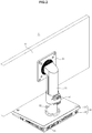
- FIG. 1 is a perspective view illustrating the front surface of a terminal in accordance with one exemplary embodiment
- FIG. 2 is a perspective view illustrating the rear surface of the terminal in accordance with an exemplary embodiment.
- a terminal 1 in accordance with this exemplary embodiment includes a display main body 10 displaying an image, a support 20 supporting the display main body 10, and a base 30 combined with the lower portion of the support 20.
- a controller such as a circuit board, may be located in the base 30.
- the device In response to a device including a controller, the device is defined as a terminal, and in response to a device not including a controller, the device is defined as a display device.
- the terminal 1 may be used as a cloud computing terminal which is connected to a server (not shown), may perform various tasks, and may store the performed tasks in the server (not shown). In this case, pieces of information physically located at different positions of respective terminals may be stored in the server (not shown), and thus these pieces of information may be integrated and managed.
- the display main body 10 is combined with one side of the support 20, and the other side of the support 20 is combined with the base 30.
- the support 20 may include a head part 21 combined with the display main body 10.
- the support 20 may include a height adjustment so as to adjust the height of the support 20.
- the height adjustment may be in a first state, i.e., a combined state in which the height of the support 20 is fixed, and in a second state, i.e., a released state in which the height of the support 20 is adjustable.
- a locking mechanism 40 configured to fix the height of the support 20 may be combined with one side of the support 20. This will be described later.
- a safety pin 50 may be combined with one side of the support 20.
- the safety pin 50 prevents sudden adjustment of the height of the terminal 1 when a user adjusts the height of the terminal 1. Since the safety pin 50, in addition to the locking mechanism 40, fixes the height of the support 20, the height of the support 20 may be adjusted by releasing the locking 40 after the locking 40 is combined with the support 20 and removing the safety pin 50.
- the safety pin 50 may prevent a safety accident which may be generated in an initial stage.
- the base 30 may include an upper housing 31 and a lower housing 32.
- Port holes 33 with which plural ports (not shown) for operation of the controller within the base 30 and the display main body 10 are combined, may be located at one side of the base 30.
- a power cord combining hole, a local area network (LAN) cable combining hole, an USB combining hole, etc. may be provided as port holes 33.
- FIGS. 1 and 2 illustrate the port holes 33 as being provided on the rear surface of the lower housing 32, the position of the port holes 33 is not limited thereto.
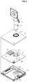
- FIG. 3 is an exploded perspective view of the base of the terminal in accordance with an exemplary embodiment.
- the terminal 1, including the controller may include a circuit board 34 within the base 30.
- the circuit board 34 may be located between the upper housing 31 and the lower housing 32.
- a first hole 31a configured for combination with the support 20 is provided on the upper housing 31.
- a second hole 34a for combination with the support 20 is provided on the circuit board 34.
- the first hole 31a and the second hole 34a may be provided at corresponding positions.
- a combining part 32a with which the support 20 is combined may be provided on the lower housing 32. Thereby, the support 20 is combined with the combining part 32a via the first hole 31a and the second hole 34a.
- the combining part 32a may protrude in the inward direction of the base 30, in order to increase the rigidity of base 30 due to combination of the support 20 with the base 30.
- the support 20 may be combined with the lower housing 32 using combining members (not shown), such as screws, from a region under the lower housing 32.
- the circuit board 34 serves as the controller.
- a device preventing the circuit board 34 from overheating may be provided on the circuit board 34.
- a heat sink 35 preventing raising of the temperature of the circuit board 34 may be provided on the circuit board 34.
- an air blower fan (not shown) configured to absorb heat from the circuit board 34 and then discharging the heat may be located on the lower housing 32.
- a third hole 34b may be provided on the circuit board 34.
- an air blowing hole 32b may be provided on the lower housing 32.
- FIG. 4 is an exploded perspective view of the support in accordance with the embodiment of an exemplary present invention.
- the support 20 includes an outer tube 23, 24 and an inner tube 25.
- the outer tube 23, 24 includes a front outer tube part 24 serving as the front surface of the support 20, and a rear outer tube part 23 serving as the rear surface of the support 20.
- the outer tube 23 and 24 may surround at least a portion of the inner tube 25. That is, when the support 20 moves in the downward direction, and thus the length of the support unit 20 decreases, the outer tube 23, 24 may completely surround the inner tube 25, but when the support 20 moves in the upward direction and thus the length of the support 20 increases, the outer tube 23, 24 does not completely surround the inner tube 25.
- a combining panel 27 to combine the support 20 with the base 30 is combined with the lower end of the inner tube 25.
- the combining part 32a of the lower housing 32 and the combining panel 27 of the support 20 are combined with each other through fastening members (not shown).
- a height adjustment configured to adjust the height of the support 20 may be located within the inner tube 25.
- the height adjustment may adjust the height of the support 20 using a gas cylinder (not shown).
- a cover member 26 may be located at the outside of the gas cylinder (not shown).
- the cover member 26 may be inserted into the inner tube 25 along grooves 26a formed on the surface of the cover member 26, and thus be moved in the downward direction or the upward direction.
- ribs (not shown) having a shape which corresponds to the shape of the grooves 26a may be provided on the inner surface of the inner tube 25.
- the gas cylinder (not shown) is compressed and the cover member 26 slides along the inner tube 25 in the downward direction.
- the user may fix the support 20 using the locking mechanism 40.
- the head part 21 may include a front panel 21a, a rear panel 21c, and a guide panel 21b, which form part of the support 20.
- the guide panel 21b may be combined with the front panel 21a, and then, the rear panel 21c may be combined with the front panel 21a through fastening members 22. Since the guide panel 21b protrudes upward from the rear panel 21c, the support 20 may be combined with the guide panel 21b after combination of the rear panel 21c with the front panel 21a.
- the locking mechanism 40 configured to fix the support 20, may be located at one side of the support 20.
- the locking mechanism 40 may include a locking body part 41 combined with the support 20, and an operation member 42 combined with the locking body part 41 and fixing the locking mechanism 40.
- the locking mechanism 40 will be described later.
- a movable part 25a may be located at a portion of the inner tube 25 contacting the locking mechanism 40.
- the movable part 25a is located at a portion of the inner tube 25 contacting the operation member 42, and in accordance with one exemplary embodiment, the movable part 25a is formed by cutting a portion of the surface of the inner tube 25 and may thus have a some degree of movability.
- FIG. 5 is a view which illustrates the locking mechanism in the combined state in accordance with an exemplary embodiment
- FIG. 6 is a view which illustrates the locking mechanism in the released state in accordance with an exemplary embodiment
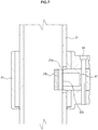
- FIG. 7 is a cross-sectional view which illustrates the locking mechanism in the combined state in accordance with an exemplary embodiment
- FIG. 8 is a cross-sectional view which illustrates the locking mechanism in the released state in accordance with an exemplary embodiment.
- the locking body part 41 is provided in a ring shape and thus that the support 20 is inserted into the ring-shaped locking body part 41, but the shape of the locking body part 41 is not limited thereto.
- At least a portion of the locking body part 41 with which the operation member 42 is combined may include an opening 41a ( FIG. 6 ).
- the opening 41a allows the operation member 42 to press the inner tube 25 with which the locking body part 41 is combined. Since the locking mechanism 40 is combined with one side of the inner tube 25 and the movable part 25a is provided on the surface of the inner tube 25 at the position at which the locking 40 is located, the locking 40 may fix the height adjustment by effectively pressing the gas cylinder (not shown) within the inner tube 25.
- the movable part 25a may be provided by cutting the surface of the inner tube 25. Since the movable part 25a is formed by cutting a designated portion of the surface of the inner tube 25, the movable part 25a may have more than a designated degree of movablity. Further, an elastic member 25b may be located at the inside of the movable part 25a. The elastic member 25b provided at the inside of the movable part 25a presses the gas cylinder (not shown) located within the inner tube 25 when the locking mechanism 40 fixes the support 20, and movement of the gas cylinder (not shown) may be stopped due to friction between the gas cylinder (not shown) and the elastic member 25b. Further, the elastic member 25b may absorb shock due to contact with the gas cylinder (not shown). The elastic member 25b may be formed of a flexible material, for example, rubber.
- the locking mechanism 40 may include the operation member 42 operated by a user to fix the height adjustment.
- the operation member 42 may be hinged to the locking body part 41 so as to be rotated relative to the locking body part 41.
- the locking body part 41 includes hinge combining parts 43 with which the operation member 42 is combined, and the hinge combining parts 43 and a fastening hole 42c of the operation member 42 are combined through a rotary pin 44.
- the operation member 42 includes a first operation part 42a combined with the surface of the locking body part 41, and a second operation part 42b combined with the surface of the inner tube 25.
- the second operation part 42b may be provided in a shape, a portion of which is protruded, and such a shape serves to guide pressing of the inner tube 25.
- the second operation part 42b may press one side of the movable part 25a provided on the surface of the inner tube 25, and the elastic member 25b located on the other side of the movable part 25a may press the gas cylinder (not shown).
- FIG. 9 is a perspective view which illustrates the rear surface of a terminal in accordance with another exemplary embodiment
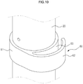
- FIG. 10 is an enlarged view of a fixing mechanism in accordance with an exemplary embodiment.
- a terminal 100 in accordance with this exemplary embodiment may further include a fixing mechanism 60.
- a fixing mechanism 60 may be provided, and the fixing mechanism 60 serves to fix such a connection member (not shown).
- the fixing mechanism 60 may include a fixing unit body part 61 combined with the support 20, and a holder part 62 extended from the fixing body part 61 to fix the connection member (not shown).
- the fixing body part 61 may be provided in a ring shape, and may thus be combined with the support 20 such that the support 20 is inserted into the ring-shaped fixing body part 61.
- the holder part 62 is extended from the fixing body part 61.
- the holder part 62 may be separated from the fixing body part 61 by a designated interval. Therefore, the connection member (not shown) may be inserted into a receiving part 63 provided between the holder part 62 and the fixing body part 61.
- the fixing mechanism 60 may be formed of a flexible material.
- the connection member (not shown) which may sag between the display main body 10 and the base 30 is arranged properly, and thus user convenience may be improved
- the terminal 100 may have a pleasing external appearance to a user.
- a display device and a terminal having the same in accordance with an exemplary embodiment may increase combining forces between a support and a base and may use the same support and base in main bodies having various sizes, thus simplifying the manufacturing process and reducing the cost of parts and assembly.
Landscapes
- Engineering & Computer Science (AREA)
- General Engineering & Computer Science (AREA)
- Theoretical Computer Science (AREA)
- Computer Hardware Design (AREA)
- Physics & Mathematics (AREA)
- General Physics & Mathematics (AREA)
- Human Computer Interaction (AREA)
- Mechanical Engineering (AREA)
- Microelectronics & Electronic Packaging (AREA)
- Power Engineering (AREA)
- Casings For Electric Apparatus (AREA)
- Devices For Indicating Variable Information By Combining Individual Elements (AREA)
Description
- Exemplary embodiments of the present invention relate to a display device and a terminal having the same, which improves a combination structure between a support supporting a main body of a display and a base and improves a height adjustment structure of the support.
- In general, display devices display an image on a screen, and correspond to a TV, a computer monitor, etc. Recently, a terminal has been manufactured with an integrated display device and a circuit board serving as a controller.
- Such a display device and a terminal having the same may include a height adjustment device so as to freely adjust the height thereof, according to surrounding circumstances or user preferences.
- When a known display device and terminal having the same height is adjusted, after a display main body is adjusted to a desired height, the display main body is forcibly fixed, which causes inconvenience to a user. Further, as the size of the main body of the display increases, a great amount of force is required to adjust the height of the display main body.
- Therefore, use of elastic force in adjustment of the height of the display main body has been proposed, and for this purpose, members, such as springs or cylinders, have been used. However, in this case, different springs or cylinders need to be used according to different sizes of display main bodies.
- " Samsung NS220 quick Setup Guide", 6 December 2011 (XP055241092) and
EP 0 965 786 A1 - Shawn Guffey: "Vizio CA24 All-In-One Disassembly (after the fact), 14 October 2014 (XP054976296), URL:https://www.youtube.com/watch?v=84rDXkiu44U, retrieved 2016-01-12 describes an All-In-One display unit.
- According to the present invention there is provided an apparatus as set forth in the appended claims. Other features of the invention will be apparent from the dependent claims, and the description which follows.
- Therefore, it is an aspect of the exemplary embodiments to provide a display device and a terminal having the same which stably support a display main body and improve a height adjustment structure of the display main body so as to be applicable to display main bodies having various sizes. Display devices per se do not form part of the present invention, except for features common to the terminal apparatus of the present disclosure.
- Additional aspects of the exemplary embodiments will be set forth in part in the description which follows and, in part, will be obvious from the description, or may be learned by practice of the exemplary embodiments. Embodiments that do not fall within the scope of the claims do not form part of the invention.
- In accordance with one aspect of the present exemplary embodiments, there may be provided a terminal according to any of the appended claims.
- These and/or other aspects of the exemplary embodiments will become apparent and more readily appreciated from the following description, taken in conjunction with the accompanying drawings of which:
-
FIG. 1 is a perspective view which illustrates the front surface of a terminal in accordance with one exemplary embodiment; -
FIG. 2 is a perspective view which illustrates the rear surface of the terminal in accordance with an exemplary embodiment; -
FIG. 3 is an exploded perspective view of a base of the terminal in accordance with an exemplary embodiment; -
FIG. 4 is an exploded perspective view of a support in accordance with an exemplary embodiment; -
FIG. 5 is a view which illustrates a locking mechanism in a combined state in accordance with an exemplary embodiment; -
FIG. 6 is a view which illustrates the locking mechanism in a released state in accordance with an exemplary embodiment; -
FIG. 7 is a cross-sectional view which illustrates the locking mechanism in the combined state in accordance with an exemplary embodiment; -
FIG. 8 is a cross-sectional view which illustrates the locking mechanism in the released state in accordance with an exemplary embodiment; -
FIG. 9 is a perspective view which illustrates the rear surface of a terminal in accordance with another exemplary embodiment; and -
FIG. 10 is an enlarged view of a fixing mechanism in accordance with an exemplary embodiment. - Reference will now be made in detail to the exemplary embodiments, examples of which are illustrated in the accompanying drawings, wherein like reference numerals refer to like elements throughout.
-
FIG. 1 is a perspective view illustrating the front surface of a terminal in accordance with one exemplary embodiment, andFIG. 2 is a perspective view illustrating the rear surface of the terminal in accordance with an exemplary embodiment. - As shown in
FIGS. 1 and2 , aterminal 1 in accordance with this exemplary embodiment includes a displaymain body 10 displaying an image, asupport 20 supporting the displaymain body 10, and abase 30 combined with the lower portion of thesupport 20. A controller, such as a circuit board, may be located in thebase 30. In response to a device including a controller, the device is defined as a terminal, and in response to a device not including a controller, the device is defined as a display device. - The
terminal 1 may be used as a cloud computing terminal which is connected to a server (not shown), may perform various tasks, and may store the performed tasks in the server (not shown). In this case, pieces of information physically located at different positions of respective terminals may be stored in the server (not shown), and thus these pieces of information may be integrated and managed. - The display
main body 10 is combined with one side of thesupport 20, and the other side of thesupport 20 is combined with thebase 30. Thesupport 20 may include ahead part 21 combined with the displaymain body 10. - The
support 20 may include a height adjustment so as to adjust the height of thesupport 20. The height adjustment may be in a first state, i.e., a combined state in which the height of thesupport 20 is fixed, and in a second state, i.e., a released state in which the height of thesupport 20 is adjustable. Alocking mechanism 40 configured to fix the height of thesupport 20 may be combined with one side of thesupport 20. This will be described later. - Further, a
safety pin 50 may be combined with one side of thesupport 20. Thesafety pin 50 prevents sudden adjustment of the height of theterminal 1 when a user adjusts the height of theterminal 1. Since thesafety pin 50, in addition to thelocking mechanism 40, fixes the height of thesupport 20, the height of thesupport 20 may be adjusted by releasing thelocking 40 after thelocking 40 is combined with thesupport 20 and removing thesafety pin 50. Thesafety pin 50 may prevent a safety accident which may be generated in an initial stage. - The
base 30 may include anupper housing 31 and alower housing 32.Port holes 33 with which plural ports (not shown) for operation of the controller within thebase 30 and the displaymain body 10 are combined, may be located at one side of thebase 30. A power cord combining hole, a local area network (LAN) cable combining hole, an USB combining hole, etc. may be provided asport holes 33. AlthoughFIGS. 1 and2 illustrate theport holes 33 as being provided on the rear surface of thelower housing 32, the position of theport holes 33 is not limited thereto. -
FIG. 3 is an exploded perspective view of the base of the terminal in accordance with an exemplary embodiment. - The
terminal 1, including the controller may include acircuit board 34 within thebase 30. Thecircuit board 34 may be located between theupper housing 31 and thelower housing 32. Afirst hole 31a configured for combination with thesupport 20 is provided on theupper housing 31. Asecond hole 34a for combination with thesupport 20 is provided on thecircuit board 34. Thefirst hole 31a and thesecond hole 34a may be provided at corresponding positions. A combiningpart 32a with which thesupport 20 is combined may be provided on thelower housing 32. Thereby, thesupport 20 is combined with the combiningpart 32a via thefirst hole 31a and thesecond hole 34a. - The combining
part 32a may protrude in the inward direction of thebase 30, in order to increase the rigidity ofbase 30 due to combination of thesupport 20 with thebase 30. Thesupport 20 may be combined with thelower housing 32 using combining members (not shown), such as screws, from a region under thelower housing 32. - The
circuit board 34 serves as the controller. A device preventing thecircuit board 34 from overheating may be provided on thecircuit board 34. For example, aheat sink 35 preventing raising of the temperature of thecircuit board 34 may be provided on thecircuit board 34. Further, an air blower fan (not shown) configured to absorb heat from thecircuit board 34 and then discharging the heat may be located on thelower housing 32. In order to allow the air blower fan (not shown) to absorb heat from thecircuit board 34, athird hole 34b may be provided on thecircuit board 34. Further, in order to allow the air blower fan (not shown) to discharge the absorbed heat, anair blowing hole 32b may be provided on thelower housing 32. -
FIG. 4 is an exploded perspective view of the support in accordance with the embodiment of an exemplary present invention. - As shown in
FIG. 4 , thesupport 20 includes anouter tube inner tube 25. Theouter tube outer tube part 24 serving as the front surface of thesupport 20, and a rearouter tube part 23 serving as the rear surface of thesupport 20. Theouter tube inner tube 25. That is, when thesupport 20 moves in the downward direction, and thus the length of thesupport unit 20 decreases, theouter tube inner tube 25, but when thesupport 20 moves in the upward direction and thus the length of thesupport 20 increases, theouter tube inner tube 25. A combiningpanel 27 to combine thesupport 20 with thebase 30 is combined with the lower end of theinner tube 25. The combiningpart 32a of thelower housing 32 and the combiningpanel 27 of thesupport 20 are combined with each other through fastening members (not shown). - A height adjustment configured to adjust the height of the
support 20 may be located within theinner tube 25. The height adjustment may adjust the height of thesupport 20 using a gas cylinder (not shown). Acover member 26 may be located at the outside of the gas cylinder (not shown). Thecover member 26 may be inserted into theinner tube 25 alonggrooves 26a formed on the surface of thecover member 26, and thus be moved in the downward direction or the upward direction. In order to guide movement of thecover member 26, ribs (not shown) having a shape which corresponds to the shape of thegrooves 26a may be provided on the inner surface of theinner tube 25. - Accordingly, in response to a user desiring to move the display
main body 10 in the downward direction, the gas cylinder (not shown) is compressed and thecover member 26 slides along theinner tube 25 in the downward direction. When the user stops movement of the displaymain body 10 at a desired position, the user may fix thesupport 20 using thelocking mechanism 40. - One side of the
support 20 may be extended to thehead part 21 with which the displaymain body 10 is combined. Thehead part 21 may include afront panel 21a, arear panel 21c, and aguide panel 21b, which form part of thesupport 20. Theguide panel 21b may be combined with thefront panel 21a, and then, therear panel 21c may be combined with thefront panel 21a throughfastening members 22. Since theguide panel 21b protrudes upward from therear panel 21c, thesupport 20 may be combined with theguide panel 21b after combination of therear panel 21c with thefront panel 21a. - The
locking mechanism 40 configured to fix thesupport 20, may be located at one side of thesupport 20. Thelocking mechanism 40 may include a lockingbody part 41 combined with thesupport 20, and anoperation member 42 combined with the lockingbody part 41 and fixing thelocking mechanism 40. Thelocking mechanism 40 will be described later. Amovable part 25a may be located at a portion of theinner tube 25 contacting thelocking mechanism 40. In more detail, themovable part 25a is located at a portion of theinner tube 25 contacting theoperation member 42, and in accordance with one exemplary embodiment, themovable part 25a is formed by cutting a portion of the surface of theinner tube 25 and may thus have a some degree of movability. -
FIG. 5 is a view which illustrates the locking mechanism in the combined state in accordance with an exemplary embodiment,FIG. 6 is a view which illustrates the locking mechanism in the released state in accordance with an exemplary embodiment,FIG. 7 is a cross-sectional view which illustrates the locking mechanism in the combined state in accordance with an exemplary embodiment, andFIG. 8 is a cross-sectional view which illustrates the locking mechanism in the released state in accordance with an exemplary embodiment. - As shown in
FIGS. 5 to 8 , the lockingbody part 41 is provided in a ring shape and thus that thesupport 20 is inserted into the ring-shapedlocking body part 41, but the shape of the lockingbody part 41 is not limited thereto. At least a portion of the lockingbody part 41 with which theoperation member 42 is combined may include anopening 41a (FIG. 6 ). Theopening 41a allows theoperation member 42 to press theinner tube 25 with which thelocking body part 41 is combined. Since thelocking mechanism 40 is combined with one side of theinner tube 25 and themovable part 25a is provided on the surface of theinner tube 25 at the position at which the locking 40 is located, the locking 40 may fix the height adjustment by effectively pressing the gas cylinder (not shown) within theinner tube 25. - The
movable part 25a may be provided by cutting the surface of theinner tube 25. Since themovable part 25a is formed by cutting a designated portion of the surface of theinner tube 25, themovable part 25a may have more than a designated degree of movablity. Further, anelastic member 25b may be located at the inside of themovable part 25a. Theelastic member 25b provided at the inside of themovable part 25a presses the gas cylinder (not shown) located within theinner tube 25 when thelocking mechanism 40 fixes thesupport 20, and movement of the gas cylinder (not shown) may be stopped due to friction between the gas cylinder (not shown) and theelastic member 25b. Further, theelastic member 25b may absorb shock due to contact with the gas cylinder (not shown). Theelastic member 25b may be formed of a flexible material, for example, rubber. - The
locking mechanism 40 may include theoperation member 42 operated by a user to fix the height adjustment. Theoperation member 42 may be hinged to the lockingbody part 41 so as to be rotated relative to the lockingbody part 41. The lockingbody part 41 includeshinge combining parts 43 with which theoperation member 42 is combined, and thehinge combining parts 43 and afastening hole 42c of theoperation member 42 are combined through arotary pin 44. - The
operation member 42 includes afirst operation part 42a combined with the surface of the lockingbody part 41, and asecond operation part 42b combined with the surface of theinner tube 25. Thesecond operation part 42b may be provided in a shape, a portion of which is protruded, and such a shape serves to guide pressing of theinner tube 25. Thesecond operation part 42b may press one side of themovable part 25a provided on the surface of theinner tube 25, and theelastic member 25b located on the other side of themovable part 25a may press the gas cylinder (not shown). -
FIG. 9 is a perspective view which illustrates the rear surface of a terminal in accordance with another exemplary embodiment, andFIG. 10 is an enlarged view of a fixing mechanism in accordance with an exemplary embodiment. - As shown in
FIGS. 9 and10 , a terminal 100 in accordance with this exemplary embodiment may further include afixing mechanism 60. Hereinafter, some parts in this embodiment which are substantially the same as those in the previous exemplary embodiment shown inFIGS. 1 to 8 are denoted by the same reference numerals even though they are depicted in different drawings, and a detailed description thereof will thus be omitted because it is considered to be unnecessary. A connection member (not shown) connecting the displaymain body 10 and the base 30 may be provided, and thefixing mechanism 60 serves to fix such a connection member (not shown). - The fixing
mechanism 60 may include a fixingunit body part 61 combined with thesupport 20, and aholder part 62 extended from the fixingbody part 61 to fix the connection member (not shown). The fixingbody part 61 may be provided in a ring shape, and may thus be combined with thesupport 20 such that thesupport 20 is inserted into the ring-shaped fixingbody part 61. Theholder part 62 is extended from the fixingbody part 61. Theholder part 62 may be separated from the fixingbody part 61 by a designated interval. Therefore, the connection member (not shown) may be inserted into a receivingpart 63 provided between theholder part 62 and the fixingbody part 61. In order to receive various connection members (not shown) having different thicknesses, the fixingmechanism 60 may be formed of a flexible material. Thereby, the connection member (not shown) which may sag between the displaymain body 10 and thebase 30 is arranged properly, and thus user convenience may be improved In addition, the terminal 100 may have a pleasing external appearance to a user. - As is apparent from the above description, a display device and a terminal having the same in accordance with an exemplary embodiment may increase combining forces between a support and a base and may use the same support and base in main bodies having various sizes, thus simplifying the manufacturing process and reducing the cost of parts and assembly.
Claims (9)
- A terminal (1) comprising:a base (30) including a circuit board (34) provided therein, and upper (31) and lower (32) housings;a display main body (10);a support unit (20) comprising an outer tube (23, 24), an inner tube (25), a cover member (26) and a head part (21) for combination with the display main body (10),wherein the outer tube (23, 24) is configured to surround at least part of the inner tube (25),wherein the inner tube (25) is combined with a combining part (32a) on the lower housing (32),wherein the cover member (26) is combined with the head part (21) and is inserted into the inner tube (25) to be moved in a downward or upward direction,wherein the cover member (26) comprises a gas cylinder that is compressed when the cover member (26) slides along the inner tube (25) in the downward direction;a first hole (31a) located on the upper housing (31) at a position that corresponds to the combining part (32a); anda second hole (34a) located on the circuit board (34) at a position that corresponds to the combining part (32a); anda locking unit (40) combined with one side of the support unit (20);wherein the inner tube (25) comprises a movable part (25a) formed by cutting a portion of the surface of the inner tube (25) and contacting the locking unit (40) to fix the height of the support unit (20) by pressing the cover member (26).
- The terminal (1) according to claim 1, wherein the combining part (32a) is protruded in the inward direction of the lower housing (32).
- The terminal (1) according to any previous claim, wherein the locking unit includes a locking unit body part (41) combined with the support unit (20), and an operation member (42) combined with the locking unit body part (41) and fixing the locking unit.
- The terminal (1) according to claim 3, wherein the operation member (42) is combined with the locking unit body part (41) so as to be rotatable relative to the locking unit body part (41).
- The terminal (1) according to claim 3, wherein the movable part (25a) is provided at one side of the inner tube (25) contacting the operation member (42), and is adapted to fix the cover member (26) according to movement of the operation member (42).
- The terminal (1) according to claim 5, further comprising an elastic member (25b) configured to absorb shock due to contact with the cover member (26) when it is combined with the inner surface of the movable part (25a).
- The terminal (1) according to claim 1, further comprising a fixing unit (61) combined with one side of the support unit (20) and fixing a connection member connecting the display main body (10) and the base (30).
- The terminal (1) according to claim 7, wherein the fixing unit includes a fixing unit body part (61) combined with the support unit (20), and a holder part (62) extended from the fixing unit body part (61) and fixing the connection member.
- The terminal (1) according to claim 1, wherein plural port holes with which plural ports for operation of the base (30) and the display main body (10) are combined are located at one side of the base (30).
Applications Claiming Priority (1)
| Application Number | Priority Date | Filing Date | Title |
|---|---|---|---|
| KR1020120108968A KR102091540B1 (en) | 2012-09-28 | 2012-09-28 | Display Device and Terminal Having the Same |
Publications (3)
| Publication Number | Publication Date |
|---|---|
| EP2713236A2 EP2713236A2 (en) | 2014-04-02 |
| EP2713236A3 EP2713236A3 (en) | 2016-02-24 |
| EP2713236B1 true EP2713236B1 (en) | 2019-11-06 |
Family
ID=49230542
Family Applications (1)
| Application Number | Title | Priority Date | Filing Date |
|---|---|---|---|
| EP13184911.9A Active EP2713236B1 (en) | 2012-09-28 | 2013-09-18 | Display device with height adjustment structure and terminal having the same |
Country Status (4)
| Country | Link |
|---|---|
| US (1) | US9715249B2 (en) |
| EP (1) | EP2713236B1 (en) |
| KR (1) | KR102091540B1 (en) |
| CN (1) | CN103717021B (en) |
Families Citing this family (12)
| Publication number | Priority date | Publication date | Assignee | Title |
|---|---|---|---|---|
| GB2519989B (en) * | 2013-11-04 | 2016-04-20 | Kenex Electro Medical Ltd | Suspension arm |
| USD812028S1 (en) * | 2015-08-05 | 2018-03-06 | Lg Electronics Inc. | Television receiver |
| USD821342S1 (en) * | 2015-10-13 | 2018-06-26 | Lg Electronics Inc. | Television receiver |
| JP6814952B2 (en) * | 2016-12-28 | 2021-01-20 | パナソニックIpマネジメント株式会社 | Display and stand set |
| US11054080B2 (en) * | 2018-04-12 | 2021-07-06 | Syncmold Enterprise Corp. | Supporting device and method for manufacturing the same |
| CN108758214A (en) * | 2018-06-20 | 2018-11-06 | 芜湖华特电子科技有限公司 | A kind of integrated protection type industrial panel computer |
| CN110778880A (en) * | 2019-11-13 | 2020-02-11 | 徐州市奥丁软件信息技术服务有限责任公司 | Adjustable computer for software development |
| CN111970904B (en) | 2020-08-19 | 2025-08-12 | 北京小米移动软件有限公司 | Support assembly and display device |
| USD987612S1 (en) * | 2020-12-02 | 2023-05-30 | Samsung Electronics Co., Ltd. | Television receiver |
| KR20220078900A (en) | 2020-12-04 | 2022-06-13 | 삼성전자주식회사 | Display apparatus |
| CN113864587B (en) * | 2021-09-30 | 2023-01-17 | 联想(北京)有限公司 | Supporting device and electronic system |
| CN117307884A (en) * | 2022-06-23 | 2023-12-29 | 深圳金立翔视效科技有限公司 | Adjust components, fixtures and display equipment |
Family Cites Families (31)
| Publication number | Priority date | Publication date | Assignee | Title |
|---|---|---|---|---|
| US3936026A (en) * | 1975-03-24 | 1976-02-03 | Ultronic Systems Corporation | Swivel base assembly |
| US5655931A (en) * | 1995-10-02 | 1997-08-12 | Framatome Connectors Usa Inc. | Electrical connector with combined electrical contact and housing mount assembly |
| GB9813075D0 (en) * | 1998-06-18 | 1998-08-19 | Hillary Christopher J | Support for flat panel members |
| SE0003117D0 (en) * | 2000-09-03 | 2000-09-03 | Fast Industriprodukter Hb | Device for mutually fixing telescopically displaced elements |
| KR100465792B1 (en) | 2002-07-06 | 2005-01-13 | 삼성전자주식회사 | Display |
| KR100630969B1 (en) * | 2002-08-24 | 2006-10-02 | 삼성전자주식회사 | Display device |
| TW543017B (en) * | 2002-09-20 | 2003-07-21 | Benq Corp | Monitor with changeable stand |
| KR100770981B1 (en) * | 2002-10-30 | 2007-10-30 | 삼성전자주식회사 | Stand of display |
| KR100826605B1 (en) * | 2002-11-11 | 2008-04-30 | 삼성전자주식회사 | Monitor device |
| KR100770984B1 (en) * | 2003-05-23 | 2007-10-30 | 삼성전자주식회사 | Display device |
| TWI246668B (en) * | 2004-12-03 | 2006-01-01 | Tul Corp | Terminal computer display assembly |
| JP2006246250A (en) * | 2005-03-04 | 2006-09-14 | Toshiba Corp | Video signal processing device |
| KR100684996B1 (en) * | 2005-03-08 | 2007-02-20 | 삼성전자주식회사 | Monitor device |
| KR100661364B1 (en) * | 2005-05-26 | 2006-12-27 | 삼성전자주식회사 | Computer system and display device |
| TWI281573B (en) * | 2005-12-06 | 2007-05-21 | Hannspree Inc | Display with multiple adjustable positions and angles |
| TWI327657B (en) * | 2006-03-16 | 2010-07-21 | Qisda Corp | Display panel and elevation adjusting base of the same |
| US20080008467A1 (en) * | 2006-07-06 | 2008-01-10 | Yi-Chuan Liu | Omni-directional surveillance network video camera |
| JP4458157B2 (en) * | 2007-11-29 | 2010-04-28 | ソニー株式会社 | Electronic component heat dissipation structure and display device |
| US7887015B2 (en) * | 2008-07-18 | 2011-02-15 | Peerless Industries, Inc. | Surface mounting system |
| TWI351594B (en) * | 2008-10-01 | 2011-11-01 | Inventec Corp | Structure of electronic device |
| CN101620959B (en) * | 2009-08-05 | 2011-07-27 | 厦门振泰成科技有限公司 | Rocker type fire preventing switch |
| KR20110055337A (en) * | 2009-11-18 | 2011-05-25 | 삼성전자주식회사 | Display device |
| US8659884B2 (en) * | 2009-12-07 | 2014-02-25 | Ergotron, Inc. | Brake stand systems |
| KR20110071546A (en) * | 2009-12-21 | 2011-06-29 | 삼성전자주식회사 | Display stand and display device including same |
| CN102345783A (en) * | 2010-08-05 | 2012-02-08 | 鸿富锦精密工业(深圳)有限公司 | Display supporting device |
| US20130292527A1 (en) * | 2010-08-17 | 2013-11-07 | Yoshihito Mochizuki | Vertically movable stand for display device |
| JP4956662B2 (en) * | 2010-10-29 | 2012-06-20 | 株式会社東芝 | Display device and electronic device |
| US8490930B2 (en) * | 2010-11-02 | 2013-07-23 | Han-Ching Huang | Telescopic supportive apparatus |
| US8717506B2 (en) * | 2011-07-20 | 2014-05-06 | Hewlett-Packard Development Company, L.P. | Electronic video display mount |
| CN102900920A (en) * | 2011-07-27 | 2013-01-30 | 鸿富锦精密工业(深圳)有限公司 | monitor support device |
| US20130075546A1 (en) * | 2011-09-23 | 2013-03-28 | Syncmold Enterprise Corp. | Monitor stand |
-
2012
- 2012-09-28 KR KR1020120108968A patent/KR102091540B1/en active Active
-
2013
- 2013-09-18 EP EP13184911.9A patent/EP2713236B1/en active Active
- 2013-09-24 CN CN201310438566.8A patent/CN103717021B/en not_active Expired - Fee Related
- 2013-09-27 US US14/039,266 patent/US9715249B2/en not_active Expired - Fee Related
Non-Patent Citations (1)
| Title |
|---|
| CHRISTOPHER NULL: "Review: Vizio CA24-A1", 17 September 2012 (2012-09-17), XP055472758, Retrieved from the Internet <URL:https://www.wired.com/2012/09/vizio-ca24-a1/> [retrieved on 20180504] * |
Also Published As
| Publication number | Publication date |
|---|---|
| KR20140042333A (en) | 2014-04-07 |
| EP2713236A3 (en) | 2016-02-24 |
| EP2713236A2 (en) | 2014-04-02 |
| CN103717021B (en) | 2018-03-27 |
| KR102091540B1 (en) | 2020-03-20 |
| CN103717021A (en) | 2014-04-09 |
| US20140092568A1 (en) | 2014-04-03 |
| US9715249B2 (en) | 2017-07-25 |
Similar Documents
| Publication | Publication Date | Title |
|---|---|---|
| US9715249B2 (en) | Display device with height adjustment structure and terminal having the same | |
| EP3945223B1 (en) | Hinge structure, folding mechanism and mobile terminal | |
| US10337665B2 (en) | Stand of electronic device | |
| KR102588619B1 (en) | Display apparatus | |
| EP2809069B1 (en) | Curved display apparatus | |
| CN101060761B (en) | Pivoting mechanism for stand and electronic apparatus | |
| US20110036965A1 (en) | Electronic device having adjustable table stand | |
| US9077436B1 (en) | Protective case for a mobile device | |
| US7633749B2 (en) | Front access enclosure | |
| US7667957B2 (en) | Thin-type display | |
| EP1785661B1 (en) | Apparatus to support a display device | |
| CN101414200A (en) | Apparatus with angle adjustment function and angle adjusting device thereof | |
| US20080296452A1 (en) | Supporting device and display apparatus having the same | |
| KR20070101140A (en) | Electronic device | |
| EP3316560B1 (en) | Rotary terminal device for portable terminal and desk lamp | |
| US8672282B2 (en) | Fixing structure for electronic device with display screen | |
| EP2752610A2 (en) | Support frame and display device including the same | |
| CN108008844B (en) | Input devices and display devices including input devices | |
| JP4896853B2 (en) | Viewfinder pan / tilt mechanism | |
| JP5395924B2 (en) | Electronics | |
| JP2008015712A (en) | Display angle adjustment device | |
| KR100465798B1 (en) | Monitor | |
| KR101777773B1 (en) | Holder for notebook computer | |
| EP4685382A1 (en) | Supporting device and display apparatus including same | |
| CN220543288U (en) | Electronic equipment |
Legal Events
| Date | Code | Title | Description |
|---|---|---|---|
| PUAI | Public reference made under article 153(3) epc to a published international application that has entered the european phase |
Free format text: ORIGINAL CODE: 0009012 |
|
| AK | Designated contracting states |
Kind code of ref document: A2 Designated state(s): AL AT BE BG CH CY CZ DE DK EE ES FI FR GB GR HR HU IE IS IT LI LT LU LV MC MK MT NL NO PL PT RO RS SE SI SK SM TR |
|
| AX | Request for extension of the european patent |
Extension state: BA ME |
|
| PUAL | Search report despatched |
Free format text: ORIGINAL CODE: 0009013 |
|
| AK | Designated contracting states |
Kind code of ref document: A3 Designated state(s): AL AT BE BG CH CY CZ DE DK EE ES FI FR GB GR HR HU IE IS IT LI LT LU LV MC MK MT NL NO PL PT RO RS SE SI SK SM TR |
|
| AX | Request for extension of the european patent |
Extension state: BA ME |
|
| RIC1 | Information provided on ipc code assigned before grant |
Ipc: F16M 11/28 20060101ALI20160121BHEP Ipc: G06F 1/18 20060101ALI20160121BHEP Ipc: F16M 11/04 20060101ALI20160121BHEP Ipc: F16M 11/00 20060101ALI20160121BHEP Ipc: G06F 1/16 20060101AFI20160121BHEP |
|
| 17P | Request for examination filed |
Effective date: 20160824 |
|
| RBV | Designated contracting states (corrected) |
Designated state(s): AL AT BE BG CH CY CZ DE DK EE ES FI FR GB GR HR HU IE IS IT LI LT LU LV MC MK MT NL NO PL PT RO RS SE SI SK SM TR |
|
| STAA | Information on the status of an ep patent application or granted ep patent |
Free format text: STATUS: EXAMINATION IS IN PROGRESS |
|
| 17Q | First examination report despatched |
Effective date: 20170502 |
|
| GRAP | Despatch of communication of intention to grant a patent |
Free format text: ORIGINAL CODE: EPIDOSNIGR1 |
|
| STAA | Information on the status of an ep patent application or granted ep patent |
Free format text: STATUS: GRANT OF PATENT IS INTENDED |
|
| INTG | Intention to grant announced |
Effective date: 20190701 |
|
| GRAS | Grant fee paid |
Free format text: ORIGINAL CODE: EPIDOSNIGR3 |
|
| GRAA | (expected) grant |
Free format text: ORIGINAL CODE: 0009210 |
|
| STAA | Information on the status of an ep patent application or granted ep patent |
Free format text: STATUS: THE PATENT HAS BEEN GRANTED |
|
| AK | Designated contracting states |
Kind code of ref document: B1 Designated state(s): AL AT BE BG CH CY CZ DE DK EE ES FI FR GB GR HR HU IE IS IT LI LT LU LV MC MK MT NL NO PL PT RO RS SE SI SK SM TR |
|
| REG | Reference to a national code |
Ref country code: GB Ref legal event code: FG4D |
|
| REG | Reference to a national code |
Ref country code: CH Ref legal event code: EP Ref country code: AT Ref legal event code: REF Ref document number: 1199635 Country of ref document: AT Kind code of ref document: T Effective date: 20191115 |
|
| REG | Reference to a national code |
Ref country code: IE Ref legal event code: FG4D |
|
| REG | Reference to a national code |
Ref country code: DE Ref legal event code: R096 Ref document number: 602013062475 Country of ref document: DE |
|
| REG | Reference to a national code |
Ref country code: NL Ref legal event code: MP Effective date: 20191106 |
|
| REG | Reference to a national code |
Ref country code: LT Ref legal event code: MG4D |
|
| PG25 | Lapsed in a contracting state [announced via postgrant information from national office to epo] |
Ref country code: BG Free format text: LAPSE BECAUSE OF FAILURE TO SUBMIT A TRANSLATION OF THE DESCRIPTION OR TO PAY THE FEE WITHIN THE PRESCRIBED TIME-LIMIT Effective date: 20200206 Ref country code: LT Free format text: LAPSE BECAUSE OF FAILURE TO SUBMIT A TRANSLATION OF THE DESCRIPTION OR TO PAY THE FEE WITHIN THE PRESCRIBED TIME-LIMIT Effective date: 20191106 Ref country code: FI Free format text: LAPSE BECAUSE OF FAILURE TO SUBMIT A TRANSLATION OF THE DESCRIPTION OR TO PAY THE FEE WITHIN THE PRESCRIBED TIME-LIMIT Effective date: 20191106 Ref country code: ES Free format text: LAPSE BECAUSE OF FAILURE TO SUBMIT A TRANSLATION OF THE DESCRIPTION OR TO PAY THE FEE WITHIN THE PRESCRIBED TIME-LIMIT Effective date: 20191106 Ref country code: NL Free format text: LAPSE BECAUSE OF FAILURE TO SUBMIT A TRANSLATION OF THE DESCRIPTION OR TO PAY THE FEE WITHIN THE PRESCRIBED TIME-LIMIT Effective date: 20191106 Ref country code: SE Free format text: LAPSE BECAUSE OF FAILURE TO SUBMIT A TRANSLATION OF THE DESCRIPTION OR TO PAY THE FEE WITHIN THE PRESCRIBED TIME-LIMIT Effective date: 20191106 Ref country code: LV Free format text: LAPSE BECAUSE OF FAILURE TO SUBMIT A TRANSLATION OF THE DESCRIPTION OR TO PAY THE FEE WITHIN THE PRESCRIBED TIME-LIMIT Effective date: 20191106 Ref country code: PL Free format text: LAPSE BECAUSE OF FAILURE TO SUBMIT A TRANSLATION OF THE DESCRIPTION OR TO PAY THE FEE WITHIN THE PRESCRIBED TIME-LIMIT Effective date: 20191106 Ref country code: PT Free format text: LAPSE BECAUSE OF FAILURE TO SUBMIT A TRANSLATION OF THE DESCRIPTION OR TO PAY THE FEE WITHIN THE PRESCRIBED TIME-LIMIT Effective date: 20200306 Ref country code: GR Free format text: LAPSE BECAUSE OF FAILURE TO SUBMIT A TRANSLATION OF THE DESCRIPTION OR TO PAY THE FEE WITHIN THE PRESCRIBED TIME-LIMIT Effective date: 20200207 Ref country code: NO Free format text: LAPSE BECAUSE OF FAILURE TO SUBMIT A TRANSLATION OF THE DESCRIPTION OR TO PAY THE FEE WITHIN THE PRESCRIBED TIME-LIMIT Effective date: 20200206 |
|
| PG25 | Lapsed in a contracting state [announced via postgrant information from national office to epo] |
Ref country code: IS Free format text: LAPSE BECAUSE OF FAILURE TO SUBMIT A TRANSLATION OF THE DESCRIPTION OR TO PAY THE FEE WITHIN THE PRESCRIBED TIME-LIMIT Effective date: 20200306 Ref country code: HR Free format text: LAPSE BECAUSE OF FAILURE TO SUBMIT A TRANSLATION OF THE DESCRIPTION OR TO PAY THE FEE WITHIN THE PRESCRIBED TIME-LIMIT Effective date: 20191106 Ref country code: RS Free format text: LAPSE BECAUSE OF FAILURE TO SUBMIT A TRANSLATION OF THE DESCRIPTION OR TO PAY THE FEE WITHIN THE PRESCRIBED TIME-LIMIT Effective date: 20191106 |
|
| PG25 | Lapsed in a contracting state [announced via postgrant information from national office to epo] |
Ref country code: AL Free format text: LAPSE BECAUSE OF FAILURE TO SUBMIT A TRANSLATION OF THE DESCRIPTION OR TO PAY THE FEE WITHIN THE PRESCRIBED TIME-LIMIT Effective date: 20191106 |
|
| PG25 | Lapsed in a contracting state [announced via postgrant information from national office to epo] |
Ref country code: CZ Free format text: LAPSE BECAUSE OF FAILURE TO SUBMIT A TRANSLATION OF THE DESCRIPTION OR TO PAY THE FEE WITHIN THE PRESCRIBED TIME-LIMIT Effective date: 20191106 Ref country code: RO Free format text: LAPSE BECAUSE OF FAILURE TO SUBMIT A TRANSLATION OF THE DESCRIPTION OR TO PAY THE FEE WITHIN THE PRESCRIBED TIME-LIMIT Effective date: 20191106 Ref country code: EE Free format text: LAPSE BECAUSE OF FAILURE TO SUBMIT A TRANSLATION OF THE DESCRIPTION OR TO PAY THE FEE WITHIN THE PRESCRIBED TIME-LIMIT Effective date: 20191106 Ref country code: DK Free format text: LAPSE BECAUSE OF FAILURE TO SUBMIT A TRANSLATION OF THE DESCRIPTION OR TO PAY THE FEE WITHIN THE PRESCRIBED TIME-LIMIT Effective date: 20191106 |
|
| REG | Reference to a national code |
Ref country code: DE Ref legal event code: R097 Ref document number: 602013062475 Country of ref document: DE |
|
| REG | Reference to a national code |
Ref country code: AT Ref legal event code: MK05 Ref document number: 1199635 Country of ref document: AT Kind code of ref document: T Effective date: 20191106 |
|
| PG25 | Lapsed in a contracting state [announced via postgrant information from national office to epo] |
Ref country code: SM Free format text: LAPSE BECAUSE OF FAILURE TO SUBMIT A TRANSLATION OF THE DESCRIPTION OR TO PAY THE FEE WITHIN THE PRESCRIBED TIME-LIMIT Effective date: 20191106 Ref country code: SK Free format text: LAPSE BECAUSE OF FAILURE TO SUBMIT A TRANSLATION OF THE DESCRIPTION OR TO PAY THE FEE WITHIN THE PRESCRIBED TIME-LIMIT Effective date: 20191106 |
|
| PLBE | No opposition filed within time limit |
Free format text: ORIGINAL CODE: 0009261 |
|
| STAA | Information on the status of an ep patent application or granted ep patent |
Free format text: STATUS: NO OPPOSITION FILED WITHIN TIME LIMIT |
|
| 26N | No opposition filed |
Effective date: 20200807 |
|
| PGFP | Annual fee paid to national office [announced via postgrant information from national office to epo] |
Ref country code: GB Payment date: 20200929 Year of fee payment: 8 Ref country code: DE Payment date: 20200922 Year of fee payment: 8 |
|
| PG25 | Lapsed in a contracting state [announced via postgrant information from national office to epo] |
Ref country code: AT Free format text: LAPSE BECAUSE OF FAILURE TO SUBMIT A TRANSLATION OF THE DESCRIPTION OR TO PAY THE FEE WITHIN THE PRESCRIBED TIME-LIMIT Effective date: 20191106 Ref country code: SI Free format text: LAPSE BECAUSE OF FAILURE TO SUBMIT A TRANSLATION OF THE DESCRIPTION OR TO PAY THE FEE WITHIN THE PRESCRIBED TIME-LIMIT Effective date: 20191106 |
|
| PG25 | Lapsed in a contracting state [announced via postgrant information from national office to epo] |
Ref country code: IT Free format text: LAPSE BECAUSE OF FAILURE TO SUBMIT A TRANSLATION OF THE DESCRIPTION OR TO PAY THE FEE WITHIN THE PRESCRIBED TIME-LIMIT Effective date: 20191106 |
|
| PG25 | Lapsed in a contracting state [announced via postgrant information from national office to epo] |
Ref country code: MC Free format text: LAPSE BECAUSE OF FAILURE TO SUBMIT A TRANSLATION OF THE DESCRIPTION OR TO PAY THE FEE WITHIN THE PRESCRIBED TIME-LIMIT Effective date: 20191106 |
|
| REG | Reference to a national code |
Ref country code: CH Ref legal event code: PL |
|
| REG | Reference to a national code |
Ref country code: BE Ref legal event code: MM Effective date: 20200930 |
|
| PG25 | Lapsed in a contracting state [announced via postgrant information from national office to epo] |
Ref country code: LU Free format text: LAPSE BECAUSE OF NON-PAYMENT OF DUE FEES Effective date: 20200918 |
|
| PG25 | Lapsed in a contracting state [announced via postgrant information from national office to epo] |
Ref country code: FR Free format text: LAPSE BECAUSE OF NON-PAYMENT OF DUE FEES Effective date: 20200930 |
|
| PG25 | Lapsed in a contracting state [announced via postgrant information from national office to epo] |
Ref country code: LI Free format text: LAPSE BECAUSE OF NON-PAYMENT OF DUE FEES Effective date: 20200930 Ref country code: IE Free format text: LAPSE BECAUSE OF NON-PAYMENT OF DUE FEES Effective date: 20200918 Ref country code: BE Free format text: LAPSE BECAUSE OF NON-PAYMENT OF DUE FEES Effective date: 20200930 Ref country code: CH Free format text: LAPSE BECAUSE OF NON-PAYMENT OF DUE FEES Effective date: 20200930 |
|
| REG | Reference to a national code |
Ref country code: DE Ref legal event code: R119 Ref document number: 602013062475 Country of ref document: DE |
|
| GBPC | Gb: european patent ceased through non-payment of renewal fee |
Effective date: 20210918 |
|
| PG25 | Lapsed in a contracting state [announced via postgrant information from national office to epo] |
Ref country code: TR Free format text: LAPSE BECAUSE OF FAILURE TO SUBMIT A TRANSLATION OF THE DESCRIPTION OR TO PAY THE FEE WITHIN THE PRESCRIBED TIME-LIMIT Effective date: 20191106 Ref country code: MT Free format text: LAPSE BECAUSE OF FAILURE TO SUBMIT A TRANSLATION OF THE DESCRIPTION OR TO PAY THE FEE WITHIN THE PRESCRIBED TIME-LIMIT Effective date: 20191106 Ref country code: CY Free format text: LAPSE BECAUSE OF FAILURE TO SUBMIT A TRANSLATION OF THE DESCRIPTION OR TO PAY THE FEE WITHIN THE PRESCRIBED TIME-LIMIT Effective date: 20191106 |
|
| PG25 | Lapsed in a contracting state [announced via postgrant information from national office to epo] |
Ref country code: MK Free format text: LAPSE BECAUSE OF FAILURE TO SUBMIT A TRANSLATION OF THE DESCRIPTION OR TO PAY THE FEE WITHIN THE PRESCRIBED TIME-LIMIT Effective date: 20191106 |
|
| PG25 | Lapsed in a contracting state [announced via postgrant information from national office to epo] |
Ref country code: GB Free format text: LAPSE BECAUSE OF NON-PAYMENT OF DUE FEES Effective date: 20210918 Ref country code: DE Free format text: LAPSE BECAUSE OF NON-PAYMENT OF DUE FEES Effective date: 20220401 |