EP2713218A2 - Fixing apparatus and image forming apparatus - Google Patents
Fixing apparatus and image forming apparatus Download PDFInfo
- Publication number
- EP2713218A2 EP2713218A2 EP13182574.7A EP13182574A EP2713218A2 EP 2713218 A2 EP2713218 A2 EP 2713218A2 EP 13182574 A EP13182574 A EP 13182574A EP 2713218 A2 EP2713218 A2 EP 2713218A2
- Authority
- EP
- European Patent Office
- Prior art keywords
- sheet
- magnetic flux
- fixing
- width
- fixing apparatus
- Prior art date
- Legal status (The legal status is an assumption and is not a legal conclusion. Google has not performed a legal analysis and makes no representation as to the accuracy of the status listed.)
- Granted
Links
Images




Classifications
-
- G—PHYSICS
- G03—PHOTOGRAPHY; CINEMATOGRAPHY; ANALOGOUS TECHNIQUES USING WAVES OTHER THAN OPTICAL WAVES; ELECTROGRAPHY; HOLOGRAPHY
- G03G—ELECTROGRAPHY; ELECTROPHOTOGRAPHY; MAGNETOGRAPHY
- G03G15/00—Apparatus for electrographic processes using a charge pattern
- G03G15/20—Apparatus for electrographic processes using a charge pattern for fixing, e.g. by using heat
- G03G15/2003—Apparatus for electrographic processes using a charge pattern for fixing, e.g. by using heat using heat
- G03G15/2014—Apparatus for electrographic processes using a charge pattern for fixing, e.g. by using heat using heat using contact heat
- G03G15/2017—Structural details of the fixing unit in general, e.g. cooling means, heat shielding means
-
- G—PHYSICS
- G03—PHOTOGRAPHY; CINEMATOGRAPHY; ANALOGOUS TECHNIQUES USING WAVES OTHER THAN OPTICAL WAVES; ELECTROGRAPHY; HOLOGRAPHY
- G03G—ELECTROGRAPHY; ELECTROPHOTOGRAPHY; MAGNETOGRAPHY
- G03G15/00—Apparatus for electrographic processes using a charge pattern
- G03G15/20—Apparatus for electrographic processes using a charge pattern for fixing, e.g. by using heat
- G03G15/2003—Apparatus for electrographic processes using a charge pattern for fixing, e.g. by using heat using heat
- G03G15/2014—Apparatus for electrographic processes using a charge pattern for fixing, e.g. by using heat using heat using contact heat
- G03G15/2017—Structural details of the fixing unit in general, e.g. cooling means, heat shielding means
- G03G15/2028—Structural details of the fixing unit in general, e.g. cooling means, heat shielding means with means for handling the copy material in the fixing nip, e.g. introduction guides, stripping means
-
- G—PHYSICS
- G03—PHOTOGRAPHY; CINEMATOGRAPHY; ANALOGOUS TECHNIQUES USING WAVES OTHER THAN OPTICAL WAVES; ELECTROGRAPHY; HOLOGRAPHY
- G03G—ELECTROGRAPHY; ELECTROPHOTOGRAPHY; MAGNETOGRAPHY
- G03G15/00—Apparatus for electrographic processes using a charge pattern
- G03G15/20—Apparatus for electrographic processes using a charge pattern for fixing, e.g. by using heat
- G03G15/2003—Apparatus for electrographic processes using a charge pattern for fixing, e.g. by using heat using heat
- G03G15/2014—Apparatus for electrographic processes using a charge pattern for fixing, e.g. by using heat using heat using contact heat
- G03G15/2039—Apparatus for electrographic processes using a charge pattern for fixing, e.g. by using heat using heat using contact heat with means for controlling the fixing temperature
- G03G15/2042—Apparatus for electrographic processes using a charge pattern for fixing, e.g. by using heat using heat using contact heat with means for controlling the fixing temperature specially for the axial heat partition
-
- G—PHYSICS
- G03—PHOTOGRAPHY; CINEMATOGRAPHY; ANALOGOUS TECHNIQUES USING WAVES OTHER THAN OPTICAL WAVES; ELECTROGRAPHY; HOLOGRAPHY
- G03G—ELECTROGRAPHY; ELECTROPHOTOGRAPHY; MAGNETOGRAPHY
- G03G2215/00—Apparatus for electrophotographic processes
- G03G2215/01—Apparatus for electrophotographic processes for producing multicoloured copies
- G03G2215/0103—Plural electrographic recording members
- G03G2215/0119—Linear arrangement adjacent plural transfer points
- G03G2215/0122—Linear arrangement adjacent plural transfer points primary transfer to an intermediate transfer belt
- G03G2215/0125—Linear arrangement adjacent plural transfer points primary transfer to an intermediate transfer belt the linear arrangement being horizontal or slanted
- G03G2215/0132—Linear arrangement adjacent plural transfer points primary transfer to an intermediate transfer belt the linear arrangement being horizontal or slanted vertical medium transport path at the secondary transfer
-
- G—PHYSICS
- G03—PHOTOGRAPHY; CINEMATOGRAPHY; ANALOGOUS TECHNIQUES USING WAVES OTHER THAN OPTICAL WAVES; ELECTROGRAPHY; HOLOGRAPHY
- G03G—ELECTROGRAPHY; ELECTROPHOTOGRAPHY; MAGNETOGRAPHY
- G03G2215/00—Apparatus for electrophotographic processes
- G03G2215/20—Details of the fixing device or porcess
- G03G2215/2003—Structural features of the fixing device
- G03G2215/2016—Heating belt
- G03G2215/2035—Heating belt the fixing nip having a stationary belt support member opposing a pressure member
Definitions
- the present invention relates to a fixing apparatus which fixes a toner image by heating the toner image formed on a sheet, and an image forming apparatus including the same.
- a copying machine, a printer, or a facsimile, which performs image formation by an electrophotographic system, an electrostatic recording system, or the like, or an image forming apparatus having multiple functions thereof is mounted with a fixing apparatus which fixes a toner image formed on a sheet.
- Japanese Patent Laid-Open No. 2006-267180 discloses a technique which adjusts a temperature of a sheet non-passing region in a fixing rotating member by inserting or removing a magnetic shielding plate in a gap portion between a fixing rotating member having an electromagnetic induction heat generating layer and an exciting coil which generates a magnetic flux. That is, when there is a risk of the excessive temperature rise in the sheet non-passing region by conveying a small-size sheet, the arrival of the magnetic flux at the fixing rotating member is blocked by inserting the magnetic shielding plate into the gap portion, and the heat generation of the fixing rotating member in the sheet non-passing region is suppressed.
- the magnetic shielding plate is made of a material having high permeability and high electrical resistance (for example, ferrite). Since the material having high electrical resistance is used, a current value becomes small, and thus, heat generation of the magnetic shielding plate itself is suppressed.
- the sheet being conveyed to the fixing nip portion is curled. Therefore, a sheet conveying guide is disposed for certainly conveying the sheet to the fixing nip portion. Even though the magnetic shielding plate intends to be disposed at the position which is the upstream side in the sheet conveying direction rather than the fixing nip portion and is in the vicinity of the fixing nip portion, the magnetic shielding plate may not be disposed due to the sheet conveying guide, or the shape of the magnetic shielding plate is restricted. Thus, the magnetic shielding function may not be sufficiently exhibited.
- the present invention is for solving the above-described problems, and in a fixing apparatus including a magnetic flux shielding means which shields a magnetic flux generated from an electromagnetic induction heating portion, it is desirable to provide a fixing apparatus which can have both functions of a magnetic flux shielding means and a sheet conveying guide.
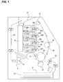
- FIG. 1 is a cross-sectional illustration diagram illustrating a configuration of an image forming apparatus equipped with a fixing apparatus according to an embodiment of the present invention
- FIG. 2 is a cross-sectional illustration diagram illustrating a configuration of the fixing apparatus according to the embodiment of the present invention and a block diagram illustrating a configuration of a control system;
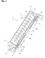
- FIG. 3 is a perspective illustration diagram illustrating a configuration of the fixing apparatus according to the embodiment of the present invention.
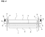
- FIG. 4 is a cross-sectional illustration diagram illustrating a configuration of the fixing apparatus according to the embodiment of the present invention.
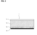
- FIG. 5 is a cross-sectional illustration diagram illustrating a configuration of a fixing member
- FIG. 6A is a schematic illustration diagram illustrating a configuration of the fixing apparatus according to the embodiment of the present invention.
- FIG. 6B is a schematic illustration diagram illustrating a configuration of the fixing apparatus according to the embodiment of the present invention.
- FIG. 7A is a schematic illustration diagram illustrating a configuration of the fixing apparatus according to the embodiment of the present invention.
- FIG. 7B is a schematic illustration diagram illustrating a configuration of the fixing apparatus according to the embodiment of the present invention.
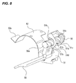
- FIG. 8 is a perspective illustration diagram of essential parts illustrating a configuration of a moving means which moves a slide member in which a magnetic flux shielding means and a sheet guide member are integrally provided;
- FIG. 9 is a block diagram illustrating a configuration of a control system of the moving means which moves the slide member in which the magnetic flux shielding means and the sheet guide member are integrally provided;
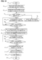
- FIG. 10 is a flowchart illustrating an operation of moving the slide member, in which the magnetic flux shielding means and the sheet guide member are integrally provided, by the moving means in correspondence to a size width of a sheet in a direction perpendicular to a sheet conveying direction.
- An image forming apparatus of the present embodiment illustrated in FIG. 1 is an example of a color image forming apparatus using an electrophotographic system.
- FIG. 1 four image forming units Y, C, M and K form color toner images of yellow, cyan, magenta, and black, respectively, and are arranged in this order from bottom to top in FIG. 1 .
- the image forming units Y, C, M and K include photosensitive drums 21Y, 21C, 21M and 21K serving as image bearing members, and charging devices 22Y, 22C, 22M and 22K serving as charging portions, respectively. Also, the image forming units Y, C, M and K include development devices 23Y, 23C, 23M and 23K serving as development portions, and cleaning devices 24Y, 24C, 24M and 24K serving as cleaning portions, respectively.
- a photosensitive drum 21 may be described on behalf of the photosensitive drums 21Y, 21C, 21M and 21K. Components constituting other image forming units will be described in a similar manner.
- Yellow toner is received in the development device 23Y of the yellow image forming unit Y.
- Cyan toner is received in the development device 23C of the cyan image forming unit C.
- Magenta toner is received in the development device 23M of the magenta image forming unit M.
- Black toner is received in the development device 23K of the black image forming unit K.
- a laser exposure device 25 is provided corresponding to the four-color image forming units Y, C, M and K.
- electrostatic latent images corresponding to scanning exposure image patterns of the respective colors are formed on the surfaces of the respective photosensitive drums 21.
- the respective color toners are supplied by the development devices 23 for the respective colors, and the electrostatic latent images formed on the surfaces of the respective photosensitive drums 21 are developed as toner images. That is, a yellow toner image is formed in the photosensitive drum 21Y of the yell image forming unit Y. A cyan toner image is formed in the photosensitive drum 21C of the cyan image forming unit C. A magenta toner image is formed in the photosensitive drum 21M of the magenta image forming unit M. A black toner image is formed in the development device 21K of the black image forming unit K.
- the respective color toner images formed on the photosensitive drums 21 of the respective image forming units Y, C, M and K are primarily transferred in a sequentially superimposed manner in a state of being aligned on an outer circumferential surface of an intermediate transfer belt 26 which rotates substantially at the same velocity in synchronization with the rotation of the respective photosensitive drums 21. In this manner, unfixed full-color toner images are synthetically formed on the intermediate transfer belt 26.
- the intermediate transfer belt 26 is stretched by three rollers, that is, a driving roller 27, a secondary-transfer-roller counter roller 28, and a tension roller 29, and is driven to rotate by the rotation driving of the driving roller 27.
- a primary transfer roller 30 provided to face the respective photosensitive drums 21 in the inner circumferential surface side of the intermediate transfer belt 26 is used.
- a primary transfer bias voltage having an opposite polarity to the toner is applied to the primary transfer roller 30 by a bias power supply which is not illustrated.
- the toner images are primarily transferred from the top of the photosensitive drums 21 of the respective image forming units Y, C, M and K to the intermediate transfer belt 26.
- the toner remaining on the photosensitive drums 21 is scraped and removed by the cleaning device 24.
- the image forming operation is performed on the respective colors of yellow, magenta, cyan, and black in synchronization with the rotation of the intermediate transfer belt 26.
- the primarily transferred toner images of the respective colors are formed on the intermediate transfer belt 26 in a sequentially superimposed manner. Also, in a monochromatic image formation (monochromatic mode), the image forming process is performed on only a target color.
- a sheet P received in a sheet cassette 31 is sent by a feed roller 32 and is separately fed one by one by a separating portion which is not illustrated. Subsequently, the sheet P is conveyed by a registration roller 33 at a predetermined timing to the intermediate transfer belt 26, which is wound around the secondary-transfer-roller counter roller 28, and a transfer nip portion, which is formed by a secondary transfer roller 34.
- the toner image formed on the outer circumferential surface of the intermediate transfer belt 26 is transferred to the top of the sheet P in a lump by the transfer bias voltage having an opposite polarity to the toner applied to the secondary transfer roller 34, the transfer bias voltage being applied by the bias power supply which is not illustrated.
- the image forming means forming unfixed toner images on the sheet P is configured by the image forming units Y, C, M and K, the intermediate transfer belt 26, and the secondary transfer roller 34. The toner remaining on the outer circumferential surface of the intermediate transfer belt 26 after the secondary transfer is scraped and removed by the cleaning device 35.
- the sheet P, on which the toner image is transferred, is conveyed toward the fixing apparatus A by a belt conveying portion 39.
- the unfixed toner image T formed on the sheet P (on the sheet) by the secondary transfer is heated and pressurized by the fixing apparatus A and is then fixed on the sheet P. Then, as a full-color printing, the sheet P is discharged to a discharge tray 37 through a discharge path 36.
- FIG. 2 is a cross-sectional illustration diagram illustrating a configuration of a fixing apparatus A according to an embodiment of the present invention and a block diagram illustrating a configuration of a control system.
- an endless fixing belt 1 has a metal layer serving as a fixing means to be disposed in the unfixed toner image T surface side (unfixed toner image surface side) formed on the sheet P.
- a pressure roller 2 is disposed to face the fixing belt 1 and is a pressurization rotating member serving as a pressurizing portion which rotates while abutting against the outer circumferential surface of the fixing belt 1.
- a pressure applying member 3 forms a fixing nip portion N by applying a pressing force between the fixing belt 1 and the pressure roller 2.
- the pressure applying member 3 is held to a metal stay 4.
- An exciting coil 38 is disposed to face the fixing belt 1 in an opposite side to the pressure roller 2.
- the exciting coil 38 as a heating portion heats a metal layer, which is embedded in the fixing belt 1, by electromagnetic induction.
- the heating by the electromagnetic induction refers to heating by Joule heat generated when a current flows around the metal layer (conductive layer) embedded in the fixing belt 1, depending on a variation in a magnetic field in the metal layer (conductive layer) when giving a variation to the magnetic field generated by a high-frequency wave applied to the exciting coil 38 as a magnetic flux generating means.
- a magnetic flux shielding core 5 which shields the magnetic flux generated from the exciting coil 38, is provided in the exciting coil 38 side of the stay 4.
- the magnetic flux shielding core 5 prevents a temperature of the fixing belt 1 from rising due to induction heating.
- the exciting coil 38 of the present embodiment uses a Litz wire as an electric wire.
- the Litz wire is made of enamel twisted wire having good high-frequency characteristic because a resistance increase due to a skin effect is small when a high-frequency wave passes through an electric wire.
- the exciting coil 38 made by winding the electric wire is formed in a shape of a ship bottom which is horizontally long, and is disposed to partially face a circumferential surface and a side surface of the fixing belt 1.
- the fixing apparatus A includes an outer magnetic core 11 and a coil holding member 13.
- the outer magnetic core 11 covers the exciting coil 38 so as to substantially prevent leakage of the magnetic field generated by the exciting coil 38, except for the metal layer (conductive layer) of the fixing belt 1, and the coil holding member 13 supports them by a resin having an insulating property.
- the exciting coil 38 is disposed to face the fixing belt 1 with a predetermined gap (clearance).
- the outer magnetic core 11 is separately provided with a core 11a and a core 11b. Also, the core 11a and the core 11b can also be integrally provided without being separated from each other. In the present embodiment, as illustrated in FIG. 3 , each of the core 11a and the core 11b in the outer magnetic core 11 is separately disposed in a longitudinal direction of the fixing apparatus A.
- a high-frequency current of 20 kHz to 60 kHz is applied from an exciting circuit 101 serving as a power supply to the exciting coil 38.
- the metal layer (conductive layer) of the fixing belt 1 is inductively heated by an alternating magnetic field generated by the exciting coil 38 (magnetic field whose magnitude and direction are repetitively changed with time).
- the fixing apparatus A includes a temperature sensor such as, for example, a thermistor.
- the temperature sensor 6 is disposed to abut against the fixing belt 1 at a position of a central inner surface portion of the fixing belt 1 in a direction perpendicular to a conveying direction of the sheet P (hereinafter, referred to as a "sheet width direction").
- the temperature sensor 6 detects a temperature of the fixing belt 1 in a passing region of the sheet P, and feeds the detection information back to a controller 102.
- the controller 102 controls power input from the exciting circuit 101 to the exciting coil 38, such that the temperature of the fixing belt 1 detected by the temperature sensor 6 is maintained at a predetermined target temperature (fixing temperature).
- the controller 102 performs temperature regulation by controlling the exciting circuit 101, based on a detection value of the temperature sensor 6, and controlling power input to the exciting coil 38 while changing a frequency of a high-frequency current.
- the temperature sensor 6 of the present embodiment is attached to the pressure applying member 3 through an elastic support member. Even when a position variation such as a rippling of the abutting surface with respect to the temperature sensor 6 of the fixing belt 1 occurs, the temperature sensor 6 is configured to follow this and maintain a good contact state.
- the pressure roller 2 is driven to rotate by a motor 14 serving as a driving source controlled by the controller 102.
- the fixing belt 1 as a fixing rotating member is rotated by the pressure roller 2.
- the pressure roller 2 and the fixing belt 1 are driven to rotate at substantially the same circumferential velocity as the conveying velocity of the sheet P bearing the unfixed toner image T conveyed from the transfer nip portions of the intermediate transfer belt 26 stretched in the secondary-transfer-roller counter roller 28 and the secondary transfer roller 34.
- the outer circumferential surface of the fixing belt 1 can be rotated at a rotating velocity of 200 mm/sec, and the full-color toner image can be fixed on fifty A4-size (210 mm x 297 mm) sheet P per minute and can be fixed on thirty-two A4R-size sheet P per minute.
- the A4R-size sheet P refers to a case where the sheet P is conveyed while arranging a longitudinal direction (297 mm) of the A4-size sheet P in a sheet width direction.
- fixing flanges 10 are restricting members which restrict a left/right movement of the fixing belt 1 in a longitudinal direction and also restrict a shape of the fixing belt 1 in a circumferential direction.
- a pressure spring 9b is disposed in a contracted state between both ends 4a of the stay 4 provided to pass through the left and right fixing flanges 10 and a receiving member 9a provided in a device frame which is not illustrated. Therefore, a force which presses the stay 4 downward in FIG. 4 is applied by a pressing force of the pressure spring 9b. Therefore, a lower surface of the stay 4 and an upper surface of the pressure roller 2 are pressed, with the fixing belt 1 being disposed therebetween, to form the fixing nip portion N having a predetermined width.
- the exciting coil 38 is supplied with power from the exciting circuit 101 controlled by the controller 102, and the temperature of the fixing belt 1 is regulated to a predetermined fixing temperature.
- the sheet P where the unfixed toner image T is formed on the surface between the fixing belt 1 and the pressure roller 2 in the fixing nip portion N is guided by sheet guide members 15 and 55 and introduced into the fixing nip portion N, while the unfixed toner image T side is directed toward the fixing belt 1 side.
- the sheet guide member 55 is disposed in an upstream side in the sheet conveying direction (right side of FIG. 2 ) rather than the fixing nip portion N.
- the sheet P comes into close contact with the outer circumferential surface of the fixing belt 1 in the fixing nip portion N, and the sheet P is cramped by the fixing belt 1 and the pressure roller 2 and is conveyed by the fixing nip portion N. Therefore, the heat of the fixing belt 1 is applied to the unfixed toner image T on the sheet P, and the unfixed toner image T receives the pressing force of the fixing nip portion N and is hot-pressed and fixed on the surface of the sheet P. Due to surface deformation of the fixing belt 1 in an outlet portion of the fixing nip portion N, the sheet P passing through the fixing nip portion N is separated from the outer circumferential surface of the fixing belt 1 and is conveyed to the outside of the fixing apparatus A.
- FIG. 5 is a model illustration diagram illustrating a layer configuration of the fixing belt 1.
- the fixing belt 1 includes a base layer 1a made of a metal layer having an inner diameter of about 20 mm to 40 mm.
- An elastic layer 1b made of a heat-resisting rubber layer is provided in an outer circumference of the base layer 1a.
- a thickness of the elastic layer 1b can be set in a range of 100 ⁇ m to 1,000 ⁇ m. In the present embodiment, warming-up time is shortened by reducing heat capacity of the fixing belt 1, and a thickness of the elastic layer 1b is set to 1,000 ⁇ m, taking into consideration that appropriate fixing images are obtained when color images are fixed.
- a surface toner parting layer 1c made of a fluorine resin layer is provided in the outer circumference of the elastic layer 1b.
- the surface toner parting layer 1c is made of, for example, tetrafluoroethylene-perfluoroalkyl ether copolymer (PFA) or polytetrafluoroethylene (PTFE).
- a slipping layer 1d which has good sliding property and has a thickness of about 10 ⁇ m to 50 ⁇ m, may be provided for reducing sliding friction of the inner circumferential surface of the fixing belt 1 and the temperature sensor 6.
- a metal such as an iron alloy, copper, or silver may be appropriately selected.
- the pressure roller 2 which forms the fixing nip portion N between the pressure roller 2 and the fixing belt 1 is provided with an elastic layer 2b made of a rubber layer in an outer circumference of a metal core bar 2a. Also, a toner parting layer 2c is provided on an outer circumferential surface of an elastic layer 2b.
- the pressure roller 2 of the present embodiment has an outer diameter of 40 mm.
- the configuration of the exciting coil 38 in the present embodiment will be described with reference to FIG. 2 .
- the fixing belt 1 and the exciting coil 38 are maintained in an electrically insulating state by a mold having a thickness of about 2 mm.
- the fixing belt 1 and the exciting coil 38 are disposed spaced apart from each other by a predetermined distance. Due to the alternating magnetic field generated by the exciting coil 38, the metal layer (conductive layer) provided in the base layer 1a of the fixing belt 1 is uniformly heated by induction heating.
- a high-frequency current of 20 kHz to 60 kHz is applied to the exciting coil 38 by the exciting circuit 101.
- the metal layer (conductive layer) provided in the base layer 1a of the fixing belt 1 is inductively heated.
- the controller 102 changes a frequency of the high-frequency current of the exciting circuit 101, based on the detection value of the temperature sensor 6. Therefore, the temperature of the fixing belt 1 is regulated by controlling the power input to the exciting coil 38.
- the exciting coil 38 is disposed in the outside of the fixing belt 1 which becomes high temperature. Therefore, the temperature of the exciting coil 38 hardly becomes high, and the electrical resistance thereof does not increase. Hence, even when the high-frequency current flows through the exciting coil 38, loss caused by Joule heat can be reduced. Also, the arrangement of the exciting coil 38 in the outside of the fixing belt 1 contributes to the diameter reduction and low heat capacity of the fixing belt 1, and improves energy-saving performance.
- ⁇ Magnetic flux shielding means Corresponding to Sheet Size> As described above, in the conventional fixing apparatus, when small-size sheet P is heated in succession in a large amount, an excessive temperature rise occurs in a non-passing region of the sheet P.
- the following description will be given of a temperature control portion which controls a heat generation distribution in the longitudinal direction of the fixing apparatus A (width direction perpendicular to the sheet conveying direction) according to the sheet size of each sheet P to be used, depending on the temperature rise in the non-passing region of the sheet P.
- FIGS. 6 and 7 are diagrams describing the configuration of the fixing apparatus A of the present embodiment.
- FIG. 8 is a perspective illustration diagram of essential parts illustrating a configuration of a moving means which moves a slide member 51 in which a magnetic flux shielding member 52 and a sheet guide member 55 are integrally provided.
- the sheet P is conveyed on a so-called center basis. That is, the sheet P is conveyed while matching the center of the sheet P in a width direction (direction perpendicular to the sheet conveying direction) with the center of the conveying path in a width direction.
- FIG. 6 is a diagram illustrating a case where a sheet P having a sheet width W1 of a maximum size passes through the fixing apparatus A.
- FIG. 7 is a diagram illustrating a case where a sheet P having a sheet width W2 of a minimum size passes through the fixing apparatus A.
- the outer magnetic core 11 disposed in the longitudinal direction of the fixing apparatus A affects a heat generation width of the fixing belt 1.
- the outer magnetic core 11 is disposed to match the maximum width of the outer magnetic core 11 with the sheet width W1 of the maximum size so as to correspond to the sheet width W1 of the maximum size of the sheet P.
- the magnetic flux shielding member 52 is provided to serve as a magnetic flux shielding means which shields a magnetic flux generated from the exciting coil 38 according to each size of the sheet P to be used.
- the magnetic flux shielding member 52 may be made of a non-magnetic material, such as aluminum, copper, silver, gold, and brass, or an alloy thereof, and may be made of permalloy including ferrite or Fe-Ni alloy, whose main component is an iron oxide being a high-permeability member.
- the magnetic flux shielding member 52 may be disposed between the fixing belt 1 and the magnetic flux shielding core 5, as well as between the exciting coil 38 and the fixing belt 1.
- a copper plate is used as the magnetic flux shielding member 52 and is movably inserted between the exciting coil 38 and the fixing belt 1 in the sheet width direction. Inserting the magnetic flux shielding member 52 made of the copper plate between the exciting coil 38 and the fixing belt 1 obtains an effect that the passing of the magnetic flux, which is formed by the exciting coil 38 and the outer magnetic core 11, through the metal layer (conductive layer) provided in the base layer 1a of the fixing belt 1 is weakened. Therefore, induction heating of the metal layer (conductive layer) is reduced.
- a lead screw member 50 axially supported rotatably to bearing portions 13a and 13b is provided in the coil holding member 13 which is provided at both ends of the fixing apparatus A.
- the lead screw member 50 is disposed in a direction perpendicular to the sheet conveying direction, and male screw portions 50a and 50b of opposite directions are formed on the left and right sides thereof.
- a pair of slide members 51 having a boss portion 51b constituting female screw portions respectively engaged with the male screw portions 50a and 50b of the lead screw member 50 are movably provided in a direction in which they become close to or far away from each other along the lead screw member 50.
- the lead screw member 50 is driven to rotate by a motor 7 serving as a driving source controlled by a controller 103 illustrated in FIGS. 6 and 7 . In this manner, the pair of slide members 51 are moved along the lead screw member 50 in a direction perpendicular to the sheet conveying direction in a direction in which they become close to or far away from each other.
- the magnetic flux shielding member 52 and the sheet guide member 55 are supported to the slide members 51 serving as support means.
- the sheet guide member 55 is provided in the center side (inner side) rather than the magnetic flux shielding member 52.
- the slide member 51 supporting the magnetic flux shielding member 52 and the sheet guide member 55 are supported to the lead screw member 50. That is, the magnetic flux shielding member 52 and the sheet guide member 55 are configured to move in a direction perpendicular to the sheet conveying direction integrally with the slide member 51, depending on the rotation of the lead screw member 50.
- the lead screw member 50 or the motor 7 configures a moving means which move the slide member 51 supporting the magnetic flux shielding member 52 and the sheet guide member 55 in a direction perpendicular to the sheet conveying direction.
- the moving means moves the magnetic flux shielding member 52 and the sheet guide member 55 in the direction perpendicular to the sheet conveying direction according to the size width of the direction perpendicular to the sheet conveying direction of the sheet P to be used.
- the heat generation distribution in the longitudinal direction of the fixing belt 1 is controlled according to the size of the sheet P.
- the magnetic flux shielding members 52 are disposed at both ends of the fixing belt 1 in the longitudinal direction of the fixing apparatus A.
- a width W3 of the magnetic flux shielding members 52 disposed at both ends of the fixing belt 1 in the direction perpendicular to the sheet conveying direction (hereinafter, "width of the magnetic flux shielding member 52 in an axial direction") is as follows. That is, as illustrated in FIG. 6A , the width W3 is set to below a width which can be disposed between a support side plate 12 of the fixing belt 1 and an outermost end of the outer magnetic core 11 in the longitudinal direction.
- the width W3 of the magnetic flux shielding member 52 in the axial direction needs to be sufficiently wide. Also, the width W3 of the magnetic flux shielding member 52 in the axial direction needs to be sufficiently wide so that the maximum heat generation width of the fixing belt 1 does not reduce the sheet width W1 of the maximum size of the sheet P to be used. Also, the width W3 of the magnetic flux shielding member 52 in the axial direction needs to be wide enough to be disposed without expanding the width of the fixing apparatus A in the longitudinal direction.
- the width W3 of the magnetic flux shielding member 52 in the axial direction and the width W4 of the outer magnetic core 11 in the direction perpendicular to the sheet conveying direction are set to satisfy the relation of Math. 1 below. Also, hereinafter, the width of the outer magnetic core 11 in the direction perpendicular to the sheet conveying direction will be referred to as "width of the outer magnetic core 11 in the axial direction”. W ⁇ 3 > W ⁇ 4
- the width W3 of the magnetic flux shielding member 52 is set to be larger than the width W4 of the outer magnetic core 11 in the axial direction.
- the magnetic flux shielding member 52 is disposed outside the region of the sheet width W1 of the maximum size of the sheet P to be used. At this time, the magnetic flux shielding member 52 is disposed at a position outside the region where the outer magnetic core 11 and the fixing belt 1 face each other. Therefore, as illustrated in FIG. 6B , it is possible to secure the heat generation distribution corresponding to the sheet width W1 of the maximum size of the sheet P to be used.
- the position of the slide member 51 illustrated in FIG. 6A is set as an initial position (home position).
- the lead screw member 50 is rotated in a predetermined direction by rotating the motor 7 from the home position in a predetermined direction by the controller 103. Therefore, the pair of slide members 51 is moved to the center portion. That is, as the pair of slide members 51 is closer to each other, the pair of slide members 51 moves in a direction of an arrow E of FIG. 7A .
- the magnetic flux shielding members 52 provided in the slide members 51 also move in the direction of the arrow E of FIG. 7A .
- the magnetic flux shielding member 52 is disposed in a region where the outer magnetic core 11 and the fixing belt 1 face each other. This weakens the passing of the magnetic flux, which is formed by the exciting coil 38 and the outer magnetic core 11, through the metal layer (conductive layer) provided in the base layer 1a of the fixing belt 1. This reduces the induction heating of the metal layer (conductive layer) provided in the base layer 1a of the fixing belt 1.
- the magnetic flux shielding member 52 is inserted into both ends of the fixing belt 1 in the longitudinal direction. This weakens the magnetic flux passing through the metal layer (conductive layer) provided in the base layer 1a of the fixing belt 1. Therefore, as illustrated in FIG. 7B , it is possible to form the heat generation distribution corresponding to the sheet width W2 of the minimum size of the sheet P.
- the magnetic flux shielding member 52 is disposed between the fixing belt 1 and the exciting coil 38, and is held to the slide member 51 movably provided in the longitudinal direction of the fixing apparatus A.
- the slide member 51 is movably supported along the lead screw member 50, such that the magnetic flux shielding member 52 and the sheet guide member 55 moving integrally with the slide member 51 in the longitudinal direction of the fixing apparatus A does not come into contact with the rotating fixing belt 1.
- stopper portions 13c and 13d are disposed in parallel to the lead screw member 50 and are provided over the moving range of the pair of slide members 51.
- a leading end portion 52a of the magnetic flux shielding member 52 slidably abuts while being slidably fitted between the stopper portions 13c and 13d provided in the coil holding member 13. Therefore, the slide members 51 are movably supported along the lead screw member 50 in a stable posture. This can prevent the magnetic flux shielding member 52 from coming into contact with the fixing belt 1.
- the slide members 51 holding the magnetic flux shielding member 52 and the sheet guide member 55 are symmetrically disposed at both ends of the fixing apparatus A in the longitudinal direction with respect to the center reference through which the sheet P passes.
- the lead screw member 50 is provided with the male screw portions 50a and 50b including a right-handed screw and a left-handed screw at one end and the other end, respectively.
- the lead screw member 50 is provided in parallel in the longitudinal direction of the coil holding member 13.
- Axial end portions 50c and 50d at one end and the other end of the lead screw member 50 are axially supported rotatably to the bearing portions 13a and 13b provided at both ends of the coil holding member 13 in the longitudinal direction.
- the magnetic flux shielding member 52 and the sheet guide member 55 are held by the pair of slide members 51, respectively.
- the slide members 51 are moved symmetrically to the center reference line (center of the sheet conveying path in the width direction), through which the sheet P passes, along the lead screw member 50 through the boss portions 51b respectively engaged with the male screw portions 50a and 50b of the lead screw member 50 driven to rotate by the motor 7.
- the pair of slide members 51 is moved in a direction of an arrow E illustrated in FIG. 3 .
- the lead screw member 50 is rotated in a direction of an arrow H illustrated in FIG. 3 .
- the pair of slide members 51 is moved in a direction of an arrow F illustrated in FIG. 3 .
- cylindrical portions 51c and 51d respectively provided in the slide members 51 are fitted to the outside of the male screw portions 50a and 50b of the lead screw member 50.
- the boss portions 51b protruding on the inner circumferential surfaces of the cylindrical portions 51c and 51d are connected and engaged with the male screw portions 50a and 50b.
- the boss portions 51b protruding on the inner circumferential surfaces of the cylindrical portions 51c and 51d fitted to the outside of the male screw portions 50a and 50b of the lead screw member 50 are configured to slidably contact the male screw portions 50a and 50b at three points so as to reduce the contact area with the male screw portions 50a and 50b. Also, the boss portions 51b may be configured to slidably contact the male screw portions 50a and 50b at more than three points.
- the moving means which moves the magnetic flux shielding member 52 and the sheet guide member 55 in the longitudinal direction of the fixing apparatus A
- the use of the lead screw member 50 has been exemplified.
- a moving means using a wire or a rack gear may also be used herein as long as the moving means is configured to symmetrically move the magnetic flux shielding member 52 with respect to the center reference line through which the sheet P passes.
- the controller 103 which controls the operation of moving the slide members 51 is provided.
- the controller 103 rotates the motor 7 which rotates the lead screw member 50 in a predetermined direction.
- a home position sensor 8 is provided as a position detection portion of the slide members 51.
- the controller 103 controls the operation of the motor 7, based on a detection signal of the home position sensor 8.
- the home position sensor 8 of the present embodiment is configured by a photo interrupter.
- the home position sensor 8 is turned on/off by transmitting/blocking an optical path of the photo interrupter by a flag portion 51a provided in the slide member 51.
- the home position sensor 8 detects an edge of the flag portion 51a and a position control of the slide members 51 is performed.
- FIG. 9 is a block diagram illustrating a configuration of a control system of the moving means which moves the slide member 51 in which the magnetic flux shielding member 52 and the sheet guide member 55 are integrally provided.
- FIG. 10 is a flowchart describing an operation of moving the slide member 51, in which the magnetic flux shielding member 52 and the sheet guide member 55 are integrally provided, by the moving means in correspondence to the size width of the sheet P in the direction perpendicular to the sheet conveying direction.
- the controller 103 reads a size signal of the sheet P, which is input by a sheet size input portion 16 in a manipulation portion or a computer provided in the image forming apparatus, and controls the motor 7 based on the detection signal of the home position sensor 8.
- step S1 of FIG. 10 a print job is started.
- the controller 103 reads the size signal of the sheet P used, which is input from the sheet size input portion 16 illustrated in FIG. 9 .
- step S3 the controller 103 arithmetically operates and determines pulse number C1 input to the motor 7, so as to move the slide member 51 from an initial position illustrated in FIG. 6A by a predetermined distance according to the read size signal of the sheet P.
- step S4 to S8 the controller 103 reads a detection signal of the home position sensor 8.
- the controller 103 controls the motor 7 such that the slide member 51 is returned to the initial position illustrated in FIG. 6A according to an ON/OFF state of the home position sensor 8.
- step S4 when the detection signal of the home position sensor 8 is in the OFF state, it is determined that the slide member 51 is not returned to the initial position illustrated in FIG. 6A , and is deviated toward the center portion in a direction perpendicular to a sheet conveying direction. Therefore, the process proceeds to step S5.
- step S5 the controller 103 rotates the motor 7 to move the slide member 51 in a direction of an arrow F of FIG. 6A .
- step S6 after the flag portion 51a provided in the slide member 51 passes through a detection position of the home position sensor 8 and the detection signal of the home position sensor 8 changes from OFF to ON, the process proceeds to step S7.
- step S7 the controller 103 performs control such that a predetermined pulse number D1 is input to the motor 7. Therefore, the operation of moving the slide member 51 is ended at a position moved by a distance X0 illustrated in FIG. 6A .
- step S8 the slide member 51 is located at the initial position illustrated in FIG. 6A .
- step S9 the controller 103 rotates the motor 7 to move the slide member 51 in a direction of an arrow E of FIG. 7A .
- step S5 the controller 103 reversely rotates the motor 7 to move the slide member 51 in a direction of an arrow F of FIG. 7A .
- step S6 after the flag portion 51a provided in the slide member 51 passes through the detection position of the home position sensor 8 and the detection signal of the home position sensor 8 changes from OFF to ON, the process proceeds to step S7.
- step S7 the controller 103 inputs a predetermined pulse number D1 to the motor 7. Therefore, the operation of moving the slide member 51 is ended at a position moved by a distance X0 illustrated in FIG. 6A .
- step S8 the slide member 51 is located at the initial position illustrated in FIG. 6A .
- step S10 the controller 103 rotates the motor 7 to move the slide member 51 in a direction of an arrow E of FIG. 7A .
- step S11 the flag portion 51a provided in the slide member 51 passes through the detection position of the home position sensor 8.
- step S12 the controller 103 inputs a predetermined pulse number C1 to the motor 7. Therefore, in step S13, the operation of moving the slide member 51 is ended at a position moved by a distance X1 illustrated in FIG. 7A .
- step S14 a print is started.
- step S14 the print is started without moving the slide member 51 from the initial position illustrated in FIG. 6A .
- the width W L of the longitudinal direction of the sheet P passing through the fixing apparatus A may have a value given in Math. 2 below, which is between the sheet width W1 of the maximum size and the sheet width W2 of the minimum size of the sheet P to be used.
- step S3 the controller 103 moves the slide member 51 from the initial position illustrated in FIG. 6A by a predetermined distance in the sheet width direction according to the sheet size signal of the width W L of the sheet P in the longitudinal direction, which is read from the sheet size input portion 16. Therefore, the controller 103 changes the pulse number C1 input to the motor 7. As described above, it is possible to form a heat generation distribution which does not cause a temperature rise in the non-passing region of the sheet P corresponding to the width W L of the longitudinal direction of the sheet P to be used, or does not cause fixing failure at the sheet width end portion of the sheet P.
- the sheet guide member 55 will be described with reference to FIGS. 2 and 8 . As illustrated in FIG. 8 , the sheet guide member 55 is provided integrally with the slide member 51. Therefore, the sheet guide member 55 is moved integrally with the slide member 51 along the lead screw member 50.
- the sheet guide member 55 is a member which guides the sheet P conveyed toward the fixing apparatus A.
- the sheet guide member 55 is made of a metal or a resin.
- fluorine coating having good sliding property may be performed on the sheet guide member 55, or a sheet having good sliding property may be attached to the sheet guide member 55.
- the sheet guide member 55 may be configured to be detachable from the slide member 51 for the purpose of cleaning or replacement.
- the sheet guide member 55 is configured to be movable integrally with the slide member 51 in the region between the sheet width W1 of the maximum size and the sheet width W2 of the minimum size of the sheet P to be used.
- the sheet guide member 55 is disposed at the sheet width end portion of the sheet P to be used. As illustrated in FIG. 6A , even when using the usable maximum-size sheet (sheet width W1), the sheet guide member 55 is moved integrally with the slide member 51. Also, as illustrated in FIG. 7A , even when using the usable minimum-size sheet (sheet width W2), the sheet guide member 55 is moved integrally with the slide member 51.
- the sheet guide member 55 is moved such that the sheet guide member 55 is disposed at the sheet width end portion of the sheet P.
- the sheet guide member 55 is disposed in the vicinity of the fixing nip portion N and is disposed in an upstream side in the sheet conveying direction rather than the fixing nip portion N, such that the sheet P can be conveyed from the upstream side in the conveying direction of the sheet P (right side of FIG. 2 ) to the fixing nip portion N.
- the leading end portion P1 of the sheet P is certainly guided and cramped to the fixing nip portion N. Hence, the unfixed toner image T formed on the sheet P can be fixed by the fixing apparatus A.
- the moving means including the lead screw member 50 so as to move the slide member 51 which supports the magnetic flux shielding member 52 and the sheet guide member 55 has been exemplified.
- the moving means which moves the slide member 51 is not limited to the use of the lead screw member 50.
- a configuration using a pinion gear or a rack may be provided for sliding the slide member 51 by the rotation from the motor 7.
- the pinion gear is rotated by the driving from the motor 7.
- the rack engaged with the pinion gear is provided in the slide member 51.
- the slide member 51 is slid by rotating the pinion gear by the driving from the motor 7.
- a fixing apparatus(A) includes a fixing portion(1) which comes into contact with a sheet and fixes a toner image on the sheet, a magnetic flux generating portion(38) which generates a magnetic flux so as to heat the fixing portion(1) by electromagnetic induction, a magnetic flux shielding portion(52) which shields a magnetic flux generated from the magnetic flux generating portion(38) between the fixing portion(1) and the magnetic flux generating portion(38), a support portion(51) which supports the magnetic flux shielding portion(52), a moving portion(50) which moves the support portion(51) in a with direction perpendicular to a sheet conveying direction, a controller which controls the moving portion(50) so as to move the magnetic flux generating portion(38) to a position based on a sheet size in the width direction
Landscapes
- Physics & Mathematics (AREA)
- General Physics & Mathematics (AREA)
- Fixing For Electrophotography (AREA)
Abstract
Description
- The present invention relates to a fixing apparatus which fixes a toner image by heating the toner image formed on a sheet, and an image forming apparatus including the same.
- A copying machine, a printer, or a facsimile, which performs image formation by an electrophotographic system, an electrostatic recording system, or the like, or an image forming apparatus having multiple functions thereof is mounted with a fixing apparatus which fixes a toner image formed on a sheet.
- As a heating portion which heats a fixing rotating member of a fixing apparatus, there has been proposed an electromagnetic induction heating portion which generates heat by Joule heat by generating an eddy current in an induction heating member provided in a fixing rotating member by an exciting coil. When small-size sheet is heated in succession, the following problems occur. That is, in a region (sheet passing region) where a sheet contacts a surface of a fixing rotating member, the sheet is conveyed while heat is being transferred to the sheet. In contrast, in a region (sheet non-passing region) where the sheet does not contact the surface of the fixing rotating member, no heat is applied to the fixing rotating member. Thus, heat is accumulated in the fixing rotating member, causing an excessive temperature rise. Therefore, a great temperature difference occurs between the sheet passing region and the sheet non-passing region in the fixing rotating member.
- Japanese Patent Laid-Open No.
2006-267180 - Meanwhile, when conveying a large-size sheet, the magnetic shielding plate is moved to the outside of the gap portion, and the entire area of the fixing rotating member generates heat. The magnetic shielding plate is made of a material having high permeability and high electrical resistance (for example, ferrite). Since the material having high electrical resistance is used, a current value becomes small, and thus, heat generation of the magnetic shielding plate itself is suppressed.
- As disclosed in Japanese Patent Laid-Open No.
2006-267180 - Meanwhile, in many cases, the sheet being conveyed to the fixing nip portion is curled. Therefore, a sheet conveying guide is disposed for certainly conveying the sheet to the fixing nip portion. Even though the magnetic shielding plate intends to be disposed at the position which is the upstream side in the sheet conveying direction rather than the fixing nip portion and is in the vicinity of the fixing nip portion, the magnetic shielding plate may not be disposed due to the sheet conveying guide, or the shape of the magnetic shielding plate is restricted. Thus, the magnetic shielding function may not be sufficiently exhibited.
- The present invention is for solving the above-described problems, and in a fixing apparatus including a magnetic flux shielding means which shields a magnetic flux generated from an electromagnetic induction heating portion, it is desirable to provide a fixing apparatus which can have both functions of a magnetic flux shielding means and a sheet conveying guide.
- According to the present invention, a typical fixing apparatus which fixes a toner image on a sheet by heating the toner formed on the sheet includes a fixing means which comes into contact with a sheet and fixes a toner image on the sheet, a magnetic flux generating means which generates a magnetic flux so as to heat the fixing means by electromagnetic induction, a magnetic flux shielding means which shields a magnetic flux generated from the magnetic flux generating means between the fixing means and the magnetic flux generating means, a support means which supports the magnetic flux shielding means, a moving means which moves the support means in a width direction perpendicular to a sheet conveying direction, a controller which controls the moving means so as to move the magnetic flux generating means to a position based on a sheet size in the width direction, and a sheet guide means which is supported to the support means and guides the sheet to the fixing means.
- Further features of the present invention will become apparent from the following description of exemplary embodiments with reference to the attached drawings.
-
FIG. 1 is a cross-sectional illustration diagram illustrating a configuration of an image forming apparatus equipped with a fixing apparatus according to an embodiment of the present invention; -
FIG. 2 is a cross-sectional illustration diagram illustrating a configuration of the fixing apparatus according to the embodiment of the present invention and a block diagram illustrating a configuration of a control system; -
FIG. 3 is a perspective illustration diagram illustrating a configuration of the fixing apparatus according to the embodiment of the present invention; -
FIG. 4 is a cross-sectional illustration diagram illustrating a configuration of the fixing apparatus according to the embodiment of the present invention; -
FIG. 5 is a cross-sectional illustration diagram illustrating a configuration of a fixing member; -
FIG. 6A is a schematic illustration diagram illustrating a configuration of the fixing apparatus according to the embodiment of the present invention; -
FIG. 6B is a schematic illustration diagram illustrating a configuration of the fixing apparatus according to the embodiment of the present invention; -
FIG. 7A is a schematic illustration diagram illustrating a configuration of the fixing apparatus according to the embodiment of the present invention; -
FIG. 7B is a schematic illustration diagram illustrating a configuration of the fixing apparatus according to the embodiment of the present invention; -
FIG. 8 is a perspective illustration diagram of essential parts illustrating a configuration of a moving means which moves a slide member in which a magnetic flux shielding means and a sheet guide member are integrally provided; -
FIG. 9 is a block diagram illustrating a configuration of a control system of the moving means which moves the slide member in which the magnetic flux shielding means and the sheet guide member are integrally provided; and -
FIG. 10 is a flowchart illustrating an operation of moving the slide member, in which the magnetic flux shielding means and the sheet guide member are integrally provided, by the moving means in correspondence to a size width of a sheet in a direction perpendicular to a sheet conveying direction. - An embodiment of an image forming apparatus equipped with a fixing apparatus according to the present invention will be described below in detail with reference to the drawings. Also, embodiment set forth below are exemplary embodiments of
the present invention, and the present invention is not limited to these embodiments. - <Image Forming Apparatus> An image forming apparatus of the present embodiment illustrated in
FIG. 1 is an example of a color image forming apparatus using an electrophotographic system. - In
FIG. 1 , four image forming units Y, C, M and K form color toner images of yellow, cyan, magenta, and black, respectively, and are arranged in this order from bottom to top inFIG. 1 . - The image forming units Y, C, M and K include
photosensitive drums charging devices development devices cleaning devices - Also, for convenience of description, a photosensitive drum 21 may be described on behalf of the
photosensitive drums - Yellow toner is received in the
development device 23Y of the yellow image forming unit Y. Cyan toner is received in thedevelopment device 23C of the cyan image forming unit C. Magenta toner is received in the development device 23M of the magenta image forming unit M. Black toner is received in thedevelopment device 23K of the black image forming unit K. - A
laser exposure device 25 is provided corresponding to the four-color image forming units Y, C, M and K. By performing scanning exposure on the respective photosensitive drums 21, whose surfaces are uniformly charged by the charging devices 22, by laser beams emitted from thelaser exposure device 25 according to image information, electrostatic latent images corresponding to scanning exposure image patterns of the respective colors are formed on the surfaces of the respective photosensitive drums 21. - The respective color toners are supplied by the development devices 23 for the respective colors, and the electrostatic latent images formed on the surfaces of the respective photosensitive drums 21 are developed as toner images. That is, a yellow toner image is formed in the
photosensitive drum 21Y of the yell image forming unit Y. A cyan toner image is formed in the photosensitive drum 21C of the cyan image forming unit C. A magenta toner image is formed in the photosensitive drum 21M of the magenta image forming unit M. A black toner image is formed in thedevelopment device 21K of the black image forming unit K. - The respective color toner images formed on the photosensitive drums 21 of the respective image forming units Y, C, M and K are primarily transferred in a sequentially superimposed manner in a state of being aligned on an outer circumferential surface of an
intermediate transfer belt 26 which rotates substantially at the same velocity in synchronization with the rotation of the respective photosensitive drums 21. In this manner, unfixed full-color toner images are synthetically formed on theintermediate transfer belt 26. - The
intermediate transfer belt 26 is stretched by three rollers, that is, adriving roller 27, a secondary-transfer-roller counter roller 28, and atension roller 29, and is driven to rotate by the rotation driving of thedriving roller 27. - As a primary transferring portion of the toner images from the top of the photosensitive drums 21 of the respective image forming units Y, C, M and K to the top of the
intermediate transfer belt 26, a primary transfer roller 30 provided to face the respective photosensitive drums 21 in the inner circumferential surface side of theintermediate transfer belt 26 is used. A primary transfer bias voltage having an opposite polarity to the toner is applied to the primary transfer roller 30 by a bias power supply which is not illustrated. In this manner, the toner images are primarily transferred from the top of the photosensitive drums 21 of the respective image forming units Y, C, M and K to theintermediate transfer belt 26. In the respective image forming units Y, C, M and K, after the primary transfer from the top of the photosensitive drums 21 to theintermediate transfer belt 26, the toner remaining on the photosensitive drums 21 is scraped and removed by the cleaning device 24. - The image forming operation is performed on the respective colors of yellow, magenta, cyan, and black in synchronization with the rotation of the
intermediate transfer belt 26. The primarily transferred toner images of the respective colors are formed on theintermediate transfer belt 26 in a sequentially superimposed manner. Also, in a monochromatic image formation (monochromatic mode), the image forming process is performed on only a target color. - Meanwhile, a sheet P received in a
sheet cassette 31 is sent by afeed roller 32 and is separately fed one by one by a separating portion which is not illustrated. Subsequently, the sheet P is conveyed by aregistration roller 33 at a predetermined timing to theintermediate transfer belt 26, which is wound around the secondary-transfer-roller counter roller 28, and a transfer nip portion, which is formed by asecondary transfer roller 34. - The toner image formed on the outer circumferential surface of the
intermediate transfer belt 26 is transferred to the top of the sheet P in a lump by the transfer bias voltage having an opposite polarity to the toner applied to thesecondary transfer roller 34, the transfer bias voltage being applied by the bias power supply which is not illustrated. The image forming means forming unfixed toner images on the sheet P is configured by the image forming units Y, C, M and K, theintermediate transfer belt 26, and thesecondary transfer roller 34. The toner remaining on the outer circumferential surface of theintermediate transfer belt 26 after the secondary transfer is scraped and removed by thecleaning device 35. - The sheet P, on which the toner image is transferred, is conveyed toward the fixing apparatus A by a belt conveying portion 39. The unfixed toner image T formed on the sheet P (on the sheet) by the secondary transfer is heated and pressurized by the fixing apparatus A and is then fixed on the sheet P. Then, as a full-color printing, the sheet P is discharged to a
discharge tray 37 through adischarge path 36. - <Fixing apparatus> A configuration of the fixing apparatus A will be described below with reference to
FIG. 2. FIG. 2 is a cross-sectional illustration diagram illustrating a configuration of a fixing apparatus A according to an embodiment of the present invention and a block diagram illustrating a configuration of a control system. - In
FIG. 2 , anendless fixing belt 1 has a metal layer serving as a fixing means to be disposed in the unfixed toner image T surface side (unfixed toner image surface side) formed on the sheet P.A pressure roller 2 is disposed to face the fixingbelt 1 and is a pressurization rotating member serving as a pressurizing portion which rotates while abutting against the outer circumferential surface of the fixingbelt 1. - A
pressure applying member 3 forms a fixing nip portion N by applying a pressing force between the fixingbelt 1 and thepressure roller 2. Thepressure applying member 3 is held to ametal stay 4. - An
exciting coil 38 is disposed to face the fixingbelt 1 in an opposite side to thepressure roller 2. Theexciting coil 38 as a heating portion heats a metal layer, which is embedded in the fixingbelt 1, by electromagnetic induction. Also, the heating by the electromagnetic induction refers to heating by Joule heat generated when a current flows around the metal layer (conductive layer) embedded in the fixingbelt 1, depending on a variation in a magnetic field in the metal layer (conductive layer) when giving a variation to the magnetic field generated by a high-frequency wave applied to theexciting coil 38 as a magnetic flux generating means. - Also, a magnetic
flux shielding core 5, which shields the magnetic flux generated from theexciting coil 38, is provided in theexciting coil 38 side of thestay 4. The magneticflux shielding core 5 prevents a temperature of the fixingbelt 1 from rising due to induction heating. - For example, the
exciting coil 38 of the present embodiment uses a Litz wire as an electric wire. The Litz wire is made of enamel twisted wire having good high-frequency characteristic because a resistance increase due to a skin effect is small when a high-frequency wave passes through an electric wire. Theexciting coil 38 made by winding the electric wire is formed in a shape of a ship bottom which is horizontally long, and is disposed to partially face a circumferential surface and a side surface of the fixingbelt 1. - The fixing apparatus A includes an outer
magnetic core 11 and acoil holding member 13. The outermagnetic core 11 covers theexciting coil 38 so as to substantially prevent leakage of the magnetic field generated by theexciting coil 38, except for the metal layer (conductive layer) of the fixingbelt 1, and thecoil holding member 13 supports them by a resin having an insulating property. - In the upper side of the outer circumferential surface of the fixing
belt 1 inFIG. 2 , theexciting coil 38 is disposed to face the fixingbelt 1 with a predetermined gap (clearance). - As illustrated in
FIG. 3 , in the present embodiment, the outermagnetic core 11 is separately provided with acore 11a and a core 11b. Also, thecore 11a and thecore 11b can also be integrally provided without being separated from each other. In the present embodiment, as illustrated inFIG. 3 , each of thecore 11a and the core 11b in the outermagnetic core 11 is separately disposed in a longitudinal direction of the fixing apparatus A. - In a rotating state of the fixing
belt 1, a high-frequency current of 20 kHz to 60 kHz is applied from anexciting circuit 101 serving as a power supply to theexciting coil 38. The metal layer (conductive layer) of the fixingbelt 1 is inductively heated by an alternating magnetic field generated by the exciting coil 38 (magnetic field whose magnitude and direction are repetitively changed with time). - In
FIG. 2 , the fixing apparatus A includes a temperature sensor such as, for example, a thermistor. Thetemperature sensor 6 is disposed to abut against the fixingbelt 1 at a position of a central inner surface portion of the fixingbelt 1 in a direction perpendicular to a conveying direction of the sheet P (hereinafter, referred to as a "sheet width direction"). - The
temperature sensor 6 detects a temperature of the fixingbelt 1 in a passing region of the sheet P, and feeds the detection information back to acontroller 102. Thecontroller 102 controls power input from theexciting circuit 101 to theexciting coil 38, such that the temperature of the fixingbelt 1 detected by thetemperature sensor 6 is maintained at a predetermined target temperature (fixing temperature). - That is, when the temperature of the fixing
belt 1 detected by thetemperature sensor 6 rises to a predetermined temperature, current carrying to theexciting coil 38 is controlled. In the present embodiment, in order to constantly maintain the temperature of the fixingbelt 1 at 180°C, which is the target temperature (fixing temperature), thecontroller 102 performs temperature regulation by controlling theexciting circuit 101, based on a detection value of thetemperature sensor 6, and controlling power input to theexciting coil 38 while changing a frequency of a high-frequency current. - The
temperature sensor 6 of the present embodiment is attached to thepressure applying member 3 through an elastic support member. Even when a position variation such as a rippling of the abutting surface with respect to thetemperature sensor 6 of the fixingbelt 1 occurs, thetemperature sensor 6 is configured to follow this and maintain a good contact state. - In at least the image forming operation, the
pressure roller 2 is driven to rotate by amotor 14 serving as a driving source controlled by thecontroller 102. The fixingbelt 1 as a fixing rotating member is rotated by thepressure roller 2. Thepressure roller 2 and the fixingbelt 1 are driven to rotate at substantially the same circumferential velocity as the conveying velocity of the sheet P bearing the unfixed toner image T conveyed from the transfer nip portions of theintermediate transfer belt 26 stretched in the secondary-transfer-roller counter roller 28 and thesecondary transfer roller 34. - In the case of the present embodiment, the outer circumferential surface of the fixing
belt 1 can be rotated at a rotating velocity of 200 mm/sec, and the full-color toner image can be fixed on fifty A4-size (210 mm x 297 mm) sheet P per minute and can be fixed on thirty-two A4R-size sheet P per minute. The A4R-size sheet P refers to a case where the sheet P is conveyed while arranging a longitudinal direction (297 mm) of the A4-size sheet P in a sheet width direction. - Next, the configuration of the fixing nip portion N formed by the fixing
belt 1 and thepressure roller 2 of the fixing apparatus A will be described with reference toFIG. 4 . InFIG. 4 , fixingflanges 10 are restricting members which restrict a left/right movement of the fixingbelt 1 in a longitudinal direction and also restrict a shape of the fixingbelt 1 in a circumferential direction. - A
pressure spring 9b is disposed in a contracted state between both ends 4a of thestay 4 provided to pass through the left and right fixingflanges 10 and a receivingmember 9a provided in a device frame which is not illustrated. Therefore, a force which presses thestay 4 downward inFIG. 4 is applied by a pressing force of thepressure spring 9b. Therefore, a lower surface of thestay 4 and an upper surface of thepressure roller 2 are pressed, with the fixingbelt 1 being disposed therebetween, to form the fixing nip portion N having a predetermined width. - Next, the fixing operation by the fixing apparatus A will be described with reference to
FIG. 2 . Theexciting coil 38 is supplied with power from theexciting circuit 101 controlled by thecontroller 102, and the temperature of the fixingbelt 1 is regulated to a predetermined fixing temperature. In that state, the sheet P where the unfixed toner image T is formed on the surface between the fixingbelt 1 and thepressure roller 2 in the fixing nip portion N is guided bysheet guide members belt 1 side. - In the vicinity of the fixing nip portion N formed by the fixing
belt 1 and thepressure roller 2, thesheet guide member 55 is disposed in an upstream side in the sheet conveying direction (right side ofFIG. 2 ) rather than the fixing nip portion N. - The sheet P comes into close contact with the outer circumferential surface of the fixing
belt 1 in the fixing nip portion N, and the sheet P is cramped by the fixingbelt 1 and thepressure roller 2 and is conveyed by the fixing nip portion N. Therefore, the heat of the fixingbelt 1 is applied to the unfixed toner image T on the sheet P, and the unfixed toner image T receives the pressing force of the fixing nip portion N and is hot-pressed and fixed on the surface of the sheet P. Due to surface deformation of the fixingbelt 1 in an outlet portion of the fixing nip portion N, the sheet P passing through the fixing nip portion N is separated from the outer circumferential surface of the fixingbelt 1 and is conveyed to the outside of the fixing apparatus A. - <Fixing Belt>
FIG. 5 is a model illustration diagram illustrating a layer configuration of the fixingbelt 1. The fixingbelt 1 includes abase layer 1a made of a metal layer having an inner diameter of about 20 mm to 40 mm. - An
elastic layer 1b made of a heat-resisting rubber layer is provided in an outer circumference of thebase layer 1a. A thickness of theelastic layer 1b can be set in a range of 100 µm to 1,000 µm. In the present embodiment, warming-up time is shortened by reducing heat capacity of the fixingbelt 1, and a thickness of theelastic layer 1b is set to 1,000 µm, taking into consideration that appropriate fixing images are obtained when color images are fixed. Also, a surfacetoner parting layer 1c made of a fluorine resin layer is provided in the outer circumference of theelastic layer 1b. The surfacetoner parting layer 1c is made of, for example, tetrafluoroethylene-perfluoroalkyl ether copolymer (PFA) or polytetrafluoroethylene (PTFE). - In the inner surface side of the
base layer 1a, a slippinglayer 1d, which has good sliding property and has a thickness of about 10 µm to 50 µm, may be provided for reducing sliding friction of the inner circumferential surface of the fixingbelt 1 and thetemperature sensor 6. - Also, for the
base layer 1a of the fixingbelt 1 which is made of the metal layer, a metal such as an iron alloy, copper, or silver may be appropriately selected. - <Pressure Roller> As illustrated in
FIG. 4 , thepressure roller 2 which forms the fixing nip portion N between thepressure roller 2 and the fixingbelt 1 is provided with anelastic layer 2b made of a rubber layer in an outer circumference of ametal core bar 2a. Also, atoner parting layer 2c is provided on an outer circumferential surface of anelastic layer 2b. Thepressure roller 2 of the present embodiment has an outer diameter of 40 mm. - <Exciting Coil> The configuration of the
exciting coil 38 in the present embodiment will be described with reference toFIG. 2 . The fixingbelt 1 and theexciting coil 38 are maintained in an electrically insulating state by a mold having a thickness of about 2 mm. The fixingbelt 1 and theexciting coil 38 are disposed spaced apart from each other by a predetermined distance. Due to the alternating magnetic field generated by theexciting coil 38, the metal layer (conductive layer) provided in thebase layer 1a of the fixingbelt 1 is uniformly heated by induction heating. - A high-frequency current of 20 kHz to 60 kHz is applied to the
exciting coil 38 by theexciting circuit 101. The metal layer (conductive layer) provided in thebase layer 1a of the fixingbelt 1 is inductively heated. In order to constantly maintain the temperature of the fixingbelt 1 at 180°C, which is the target temperature (fixing temperature), thecontroller 102 changes a frequency of the high-frequency current of theexciting circuit 101, based on the detection value of thetemperature sensor 6. Therefore, the temperature of the fixingbelt 1 is regulated by controlling the power input to theexciting coil 38. - The
exciting coil 38 is disposed in the outside of the fixingbelt 1 which becomes high temperature. Therefore, the temperature of theexciting coil 38 hardly becomes high, and the electrical resistance thereof does not increase. Hence, even when the high-frequency current flows through theexciting coil 38, loss caused by Joule heat can be reduced. Also, the arrangement of theexciting coil 38 in the outside of the fixingbelt 1 contributes to the diameter reduction and low heat capacity of the fixingbelt 1, and improves energy-saving performance. - <Magnetic flux shielding means Corresponding to Sheet Size> As described above, in the conventional fixing apparatus, when small-size sheet P is heated in succession in a large amount, an excessive temperature rise occurs in a non-passing region of the sheet P. The following description will be given of a temperature control portion which controls a heat generation distribution in the longitudinal direction of the fixing apparatus A (width direction perpendicular to the sheet conveying direction) according to the sheet size of each sheet P to be used, depending on the temperature rise in the non-passing region of the sheet P.
-
FIGS. 6 and7 are diagrams describing the configuration of the fixing apparatus A of the present embodiment.FIG. 8 is a perspective illustration diagram of essential parts illustrating a configuration of a moving means which moves aslide member 51 in which a magneticflux shielding member 52 and asheet guide member 55 are integrally provided. - In the fixing apparatus A of the present embodiment, the sheet P is conveyed on a so-called center basis. That is, the sheet P is conveyed while matching the center of the sheet P in a width direction (direction perpendicular to the sheet conveying direction) with the center of the conveying path in a width direction.
FIG. 6 is a diagram illustrating a case where a sheet P having a sheet width W1 of a maximum size passes through the fixing apparatus A.FIG. 7 is a diagram illustrating a case where a sheet P having a sheet width W2 of a minimum size passes through the fixing apparatus A. - The outer
magnetic core 11 disposed in the longitudinal direction of the fixing apparatus A affects a heat generation width of the fixingbelt 1. The outermagnetic core 11 is disposed to match the maximum width of the outermagnetic core 11 with the sheet width W1 of the maximum size so as to correspond to the sheet width W1 of the maximum size of the sheet P. - In the present embodiment, the magnetic
flux shielding member 52 is provided to serve as a magnetic flux shielding means which shields a magnetic flux generated from theexciting coil 38 according to each size of the sheet P to be used. The magneticflux shielding member 52 may be made of a non-magnetic material, such as aluminum, copper, silver, gold, and brass, or an alloy thereof, and may be made of permalloy including ferrite or Fe-Ni alloy, whose main component is an iron oxide being a high-permeability member. - The magnetic
flux shielding member 52 may be disposed between the fixingbelt 1 and the magneticflux shielding core 5, as well as between theexciting coil 38 and the fixingbelt 1. - In the present embodiment, as illustrated in
FIG. 8 , a copper plate is used as the magneticflux shielding member 52 and is movably inserted between theexciting coil 38 and the fixingbelt 1 in the sheet width direction. Inserting the magneticflux shielding member 52 made of the copper plate between theexciting coil 38 and the fixingbelt 1 obtains an effect that the passing of the magnetic flux, which is formed by theexciting coil 38 and the outermagnetic core 11, through the metal layer (conductive layer) provided in thebase layer 1a of the fixingbelt 1 is weakened. Therefore, induction heating of the metal layer (conductive layer) is reduced. - As illustrated in
FIGS. 3 and8 , alead screw member 50 axially supported rotatably to bearingportions coil holding member 13 which is provided at both ends of the fixing apparatus A. Thelead screw member 50 is disposed in a direction perpendicular to the sheet conveying direction, andmale screw portions - A pair of
slide members 51 having aboss portion 51b constituting female screw portions respectively engaged with themale screw portions lead screw member 50 are movably provided in a direction in which they become close to or far away from each other along thelead screw member 50. - The
lead screw member 50 is driven to rotate by amotor 7 serving as a driving source controlled by acontroller 103 illustrated inFIGS. 6 and7 . In this manner, the pair ofslide members 51 are moved along thelead screw member 50 in a direction perpendicular to the sheet conveying direction in a direction in which they become close to or far away from each other. - As illustrated in
FIG. 8 , the magneticflux shielding member 52 and thesheet guide member 55 are supported to theslide members 51 serving as support means. In the width direction perpendicular to the sheet conveying direction, thesheet guide member 55 is provided in the center side (inner side) rather than the magneticflux shielding member 52. Theslide member 51 supporting the magneticflux shielding member 52 and thesheet guide member 55 are supported to thelead screw member 50. That is, the magneticflux shielding member 52 and thesheet guide member 55 are configured to move in a direction perpendicular to the sheet conveying direction integrally with theslide member 51, depending on the rotation of thelead screw member 50. - The
lead screw member 50 or themotor 7 configures a moving means which move theslide member 51 supporting the magneticflux shielding member 52 and thesheet guide member 55 in a direction perpendicular to the sheet conveying direction. The moving means moves the magneticflux shielding member 52 and thesheet guide member 55 in the direction perpendicular to the sheet conveying direction according to the size width of the direction perpendicular to the sheet conveying direction of the sheet P to be used. - By moving the magnetic
flux shielding member 52 in the longitudinal direction of the fixing apparatus A, as illustrated inFIGS. 6B and7B , the heat generation distribution in the longitudinal direction of the fixingbelt 1 is controlled according to the size of the sheet P. - The magnetic
flux shielding members 52 are disposed at both ends of the fixingbelt 1 in the longitudinal direction of the fixing apparatus A. A width W3 of the magneticflux shielding members 52 disposed at both ends of the fixingbelt 1 in the direction perpendicular to the sheet conveying direction (hereinafter, "width of the magneticflux shielding member 52 in an axial direction") is as follows. That is, as illustrated inFIG. 6A , the width W3 is set to below a width which can be disposed between asupport side plate 12 of the fixingbelt 1 and an outermost end of the outermagnetic core 11 in the longitudinal direction. - The magnetic flux formed by the
exciting coil 38 and the outermagnetic core 11 passes through the metal layer (conductive layer) provided in thebase layer 1a of the fixingbelt 1. In order to exhibit the effect that the magnetic flux is shielded by the magneticflux shielding member 52, the width W3 of the magneticflux shielding member 52 in the axial direction needs to be sufficiently wide. Also, the width W3 of the magneticflux shielding member 52 in the axial direction needs to be sufficiently wide so that the maximum heat generation width of the fixingbelt 1 does not reduce the sheet width W1 of the maximum size of the sheet P to be used. Also, the width W3 of the magneticflux shielding member 52 in the axial direction needs to be wide enough to be disposed without expanding the width of the fixing apparatus A in the longitudinal direction. - In order to sufficiently exhibit the magnetic flux shielding effect by the magnetic
flux shielding member 52, the width W3 of the magneticflux shielding member 52 in the axial direction and the width W4 of the outermagnetic core 11 in the direction perpendicular to the sheet conveying direction are set to satisfy the relation of Math. 1 below. Also, hereinafter, the width of the outermagnetic core 11 in the direction perpendicular to the sheet conveying direction will be referred to as "width of the outermagnetic core 11 in the axial direction".
- When the condition of Math. 1 is not satisfied, that is, when the width W3 of the magnetic
flux shielding member 52 is smaller than the width W4 of the outermagnetic core 11 in the axial direction, the effect that reduces the temperature rise at the end of the sheet P in the width direction (horizontal direction ofFIG. 6 ) is lowered. Therefore, the width W3 of the magneticflux shielding member 52 is set to be larger than the width W4 of the outermagnetic core 11 in the axial direction. - As illustrated in
FIG. 6A , the magneticflux shielding member 52 is disposed outside the region of the sheet width W1 of the maximum size of the sheet P to be used. At this time, the magneticflux shielding member 52 is disposed at a position outside the region where the outermagnetic core 11 and the fixingbelt 1 face each other. Therefore, as illustrated inFIG. 6B , it is possible to secure the heat generation distribution corresponding to the sheet width W1 of the maximum size of the sheet P to be used. The position of theslide member 51 illustrated inFIG. 6A is set as an initial position (home position). - Next, a magnetic flux adjusting method by the magnetic
flux shielding member 52 when the sheet of the minimum size (sheet width W2) is used will be described with reference toFIG. 7 . Thelead screw member 50 is rotated in a predetermined direction by rotating themotor 7 from the home position in a predetermined direction by thecontroller 103. Therefore, the pair ofslide members 51 is moved to the center portion. That is, as the pair ofslide members 51 is closer to each other, the pair ofslide members 51 moves in a direction of an arrow E ofFIG. 7A . - Therefore, the magnetic
flux shielding members 52 provided in theslide members 51 also move in the direction of the arrow E ofFIG. 7A . As illustrated inFIG. 7A , the magneticflux shielding member 52 is disposed in a region where the outermagnetic core 11 and the fixingbelt 1 face each other. This weakens the passing of the magnetic flux, which is formed by theexciting coil 38 and the outermagnetic core 11, through the metal layer (conductive layer) provided in thebase layer 1a of the fixingbelt 1. This reduces the induction heating of the metal layer (conductive layer) provided in thebase layer 1a of the fixingbelt 1. - As illustrated in
FIG. 7A , the magneticflux shielding member 52 is inserted into both ends of the fixingbelt 1 in the longitudinal direction. This weakens the magnetic flux passing through the metal layer (conductive layer) provided in thebase layer 1a of the fixingbelt 1. Therefore, as illustrated inFIG. 7B , it is possible to form the heat generation distribution corresponding to the sheet width W2 of the minimum size of the sheet P. - <Moving means> Next, the configuration of the moving means which moves the
slide member 51 where the magneticflux shielding member 52 and thesheet guide member 55 are integrally provided will be described. - As illustrated in
FIGS. 2 and8 , the magneticflux shielding member 52 is disposed between the fixingbelt 1 and theexciting coil 38, and is held to theslide member 51 movably provided in the longitudinal direction of the fixing apparatus A. - The
slide member 51 is movably supported along thelead screw member 50, such that the magneticflux shielding member 52 and thesheet guide member 55 moving integrally with theslide member 51 in the longitudinal direction of the fixing apparatus A does not come into contact with therotating fixing belt 1. - In the
coil holding member 13,stopper portions lead screw member 50 and are provided over the moving range of the pair ofslide members 51. Aleading end portion 52a of the magneticflux shielding member 52 slidably abuts while being slidably fitted between thestopper portions coil holding member 13. Therefore, theslide members 51 are movably supported along thelead screw member 50 in a stable posture. This can prevent the magneticflux shielding member 52 from coming into contact with the fixingbelt 1. - In the present embodiment, as illustrated in
FIGS. 6 and7 , theslide members 51 holding the magneticflux shielding member 52 and thesheet guide member 55 are symmetrically disposed at both ends of the fixing apparatus A in the longitudinal direction with respect to the center reference through which the sheet P passes. - As illustrated in
FIG. 3 , thelead screw member 50 is provided with themale screw portions lead screw member 50 is provided in parallel in the longitudinal direction of thecoil holding member 13. -
Axial end portions lead screw member 50 are axially supported rotatably to the bearingportions coil holding member 13 in the longitudinal direction. - The magnetic
flux shielding member 52 and thesheet guide member 55 are held by the pair ofslide members 51, respectively. Theslide members 51 are moved symmetrically to the center reference line (center of the sheet conveying path in the width direction), through which the sheet P passes, along thelead screw member 50 through theboss portions 51b respectively engaged with themale screw portions lead screw member 50 driven to rotate by themotor 7. - For example, when the
lead screw member 50 is rotated in a direction of an arrow G illustrated inFIG. 3 , the pair ofslide members 51 is moved in a direction of an arrow E illustrated inFIG. 3 . Meanwhile, when thelead screw member 50 is rotated in a direction of an arrow H illustrated inFIG. 3 , the pair ofslide members 51 is moved in a direction of an arrow F illustrated inFIG. 3 . - As illustrated in
FIG. 8 ,cylindrical portions slide members 51 are fitted to the outside of themale screw portions lead screw member 50. Theboss portions 51b protruding on the inner circumferential surfaces of thecylindrical portions male screw portions - In the present embodiment, the
boss portions 51b protruding on the inner circumferential surfaces of thecylindrical portions male screw portions lead screw member 50 are configured to slidably contact themale screw portions male screw portions boss portions 51b may be configured to slidably contact themale screw portions - Also, in the present embodiment, as the moving means which moves the magnetic
flux shielding member 52 and thesheet guide member 55 in the longitudinal direction of the fixing apparatus A, the use of thelead screw member 50 has been exemplified. In addition, a moving means using a wire or a rack gear may also be used herein as long as the moving means is configured to symmetrically move the magneticflux shielding member 52 with respect to the center reference line through which the sheet P passes. - <Movement of Magnetic Flux Shielding Member> Next, the moving operation of the magnetic
flux shielding member 52 and thesheet guide member 55 with respect to the conveying region of the sheet P from the sheet width w1 of the maximum size to the sheet width W2 of the minimum size of the sheet P to be used will be described. - As illustrated in
FIGS. 6A and7B , thecontroller 103 which controls the operation of moving theslide members 51 is provided. Thecontroller 103 rotates themotor 7 which rotates thelead screw member 50 in a predetermined direction. Also, ahome position sensor 8 is provided as a position detection portion of theslide members 51. Thecontroller 103 controls the operation of themotor 7, based on a detection signal of thehome position sensor 8. - The
home position sensor 8 of the present embodiment is configured by a photo interrupter. Thehome position sensor 8 is turned on/off by transmitting/blocking an optical path of the photo interrupter by aflag portion 51a provided in theslide member 51. - Considering driving unevenness such as backlash caused by allowance between tooth surfaces of a gear train when the driving is transmitted from the
motor 7 to thelead screw member 50, thehome position sensor 8 detects an edge of theflag portion 51a and a position control of theslide members 51 is performed. -
FIG. 9 is a block diagram illustrating a configuration of a control system of the moving means which moves theslide member 51 in which the magneticflux shielding member 52 and thesheet guide member 55 are integrally provided.FIG. 10 is a flowchart describing an operation of moving theslide member 51, in which the magneticflux shielding member 52 and thesheet guide member 55 are integrally provided, by the moving means in correspondence to the size width of the sheet P in the direction perpendicular to the sheet conveying direction. - As illustrated in
FIG. 9 , thecontroller 103 reads a size signal of the sheet P, which is input by a sheetsize input portion 16 in a manipulation portion or a computer provided in the image forming apparatus, and controls themotor 7 based on the detection signal of thehome position sensor 8. - An operation of moving the
slide member 51 when the sheet P used has the sheet width W2 of the minimum size as illustrated inFIG. 7A will be described. First, in step S1 ofFIG. 10 , a print job is started. In step S2, thecontroller 103 reads the size signal of the sheet P used, which is input from the sheetsize input portion 16 illustrated inFIG. 9 . - In step S3, the
controller 103 arithmetically operates and determines pulse number C1 input to themotor 7, so as to move theslide member 51 from an initial position illustrated inFIG. 6A by a predetermined distance according to the read size signal of the sheet P. - Subsequently, in steps S4 to S8, the
controller 103 reads a detection signal of thehome position sensor 8. Thecontroller 103 controls themotor 7 such that theslide member 51 is returned to the initial position illustrated inFIG. 6A according to an ON/OFF state of thehome position sensor 8. - First, in step S4, when the detection signal of the
home position sensor 8 is in the OFF state, it is determined that theslide member 51 is not returned to the initial position illustrated inFIG. 6A , and is deviated toward the center portion in a direction perpendicular to a sheet conveying direction. Therefore, the process proceeds to step S5. In step S5, thecontroller 103 rotates themotor 7 to move theslide member 51 in a direction of an arrow F ofFIG. 6A . - In step S6, after the
flag portion 51a provided in theslide member 51 passes through a detection position of thehome position sensor 8 and the detection signal of thehome position sensor 8 changes from OFF to ON, the process proceeds to step S7. In step S7, thecontroller 103 performs control such that a predetermined pulse number D1 is input to themotor 7.
Therefore, the operation of moving theslide member 51 is ended at a position moved by a distance X0 illustrated inFIG. 6A . In step S8, theslide member 51 is located at the initial position illustrated inFIG. 6A . - Meanwhile, when the detection signal of the
home position sensor 8 is in the ON state in step S4, the process proceeds to step S9. In step S9, thecontroller 103 rotates themotor 7 to move theslide member 51 in a direction of an arrow E ofFIG. 7A . - When the
controller 103 recognizes that the detection signal of thehome position sensor 8 has changed from ON to OFF in step S4, the process proceeds to step S5. In step S5, thecontroller 103 reversely rotates themotor 7 to move theslide member 51 in a direction of an arrow F ofFIG. 7A . - Subsequently, in step S6, after the
flag portion 51a provided in theslide member 51 passes through the detection position of thehome position sensor 8 and the detection signal of thehome position sensor 8 changes from OFF to ON, the process proceeds to step S7. In step S7, thecontroller 103 inputs a predetermined pulse number D1 to themotor 7. Therefore, the operation of moving theslide member 51 is ended at a position moved by a distance X0 illustrated inFIG. 6A . In step S8, theslide member 51 is located at the initial position illustrated inFIG. 6A . - Subsequently, in step S10, the
controller 103 rotates themotor 7 to move theslide member 51 in a direction of an arrow E ofFIG. 7A . In step S11, theflag portion 51a provided in theslide member 51 passes through the detection position of thehome position sensor 8. After the detection signal of thehome position sensor 8 changes from ON to OFF, the process proceeds to step S12. In step S12, thecontroller 103 inputs a predetermined pulse number C1 to themotor 7. Therefore, in step S13, the operation of moving theslide member 51 is ended at a position moved by a distance X1 illustrated inFIG. 7A . In step S14, a print is started. - Therefore, as illustrated in
FIG. 7B , it is possible to form a heat generation distribution which does not cause a temperature rise in the non-passing region of the sheet P corresponding to the sheet width W2 of the minimum size of the sheet P to be used, or does not cause fixing failure at the end of the sheet P in the width direction. - Also, when using the usable maximum-size sheet (sheet width W1), the
controller 103 sets "0" as the pulse number C1 input to themotor 7 in step S3. In this case, in step S14, the print is started without moving theslide member 51 from the initial position illustrated inFIG. 6A . - Also, the width WL of the longitudinal direction of the sheet P passing through the fixing apparatus A may have a value given in Math. 2 below, which is between the sheet width W1 of the maximum size and the sheet width W2 of the minimum size of the sheet P to be used.

- For the sheet P of the condition expressed in Math. 2 above, the response is as follows. That is, in step S3, the
controller 103 moves theslide member 51 from the initial position illustrated inFIG. 6A by a predetermined distance in the sheet width direction according to the sheet size signal of the width WL of the sheet P in the longitudinal direction, which is read from the sheetsize input portion 16. Therefore, thecontroller 103 changes the pulse number C1 input to themotor 7. As described above, it is possible to form a heat generation distribution which does not cause a temperature rise in the non-passing region of the sheet P corresponding to the width WL of the longitudinal direction of the sheet P to be used, or does not cause fixing failure at the sheet width end portion of the sheet P. - <Sheet Guide Member> Next, the
sheet guide member 55 will be described with reference toFIGS. 2 and8 . As illustrated inFIG. 8 , thesheet guide member 55 is provided integrally with theslide member 51. Therefore, thesheet guide member 55 is moved integrally with theslide member 51 along thelead screw member 50. - The
sheet guide member 55 is a member which guides the sheet P conveyed toward the fixing apparatus A. Thesheet guide member 55 is made of a metal or a resin. In order to improve the conveyance of the sheet P, fluorine coating having good sliding property may be performed on thesheet guide member 55, or a sheet having good sliding property may be attached to thesheet guide member 55. Also, thesheet guide member 55 may be configured to be detachable from theslide member 51 for the purpose of cleaning or replacement. - As illustrated in
FIGS. 6A and7A , thesheet guide member 55 is configured to be movable integrally with theslide member 51 in the region between the sheet width W1 of the maximum size and the sheet width W2 of the minimum size of the sheet P to be used. - The
sheet guide member 55 is disposed at the sheet width end portion of the sheet P to be used. As illustrated inFIG. 6A , even when using the usable maximum-size sheet (sheet width W1), thesheet guide member 55 is moved integrally with theslide member 51. Also, as illustrated inFIG. 7A , even when using the usable minimum-size sheet (sheet width W2), thesheet guide member 55 is moved integrally with theslide member 51. - Therefore, even when the size of the sheet P to be used is any sheet width (size), the
sheet guide member 55 is moved such that thesheet guide member 55 is disposed at the sheet width end portion of the sheet P. - As illustrated in
FIG. 2 , thesheet guide member 55 is disposed in the vicinity of the fixing nip portion N and is disposed in an upstream side in the sheet conveying direction rather than the fixing nip portion N, such that the sheet P can be conveyed from the upstream side in the conveying direction of the sheet P (right side ofFIG. 2 ) to the fixing nip portion N. - Therefore, as illustrated in
FIG. 2 , when there is a curl in the leading end portion P1 of the sheet P, the curled leading end portion P1 of the sheet P is guided by thesheet guide member 55 and the sheet P is cramped to the fixing nip portion N from the leading end portion P1. - Therefore, even when a shape such as a curl exists in the leading end portion P1 of the sheet P, the leading end portion P1 of the sheet P is certainly guided and cramped to the fixing nip portion N. Hence, the unfixed toner image T formed on the sheet P can be fixed by the fixing apparatus A.
- Also, the moving means including the
lead screw member 50 so as to move theslide member 51 which supports the magneticflux shielding member 52 and thesheet guide member 55 has been exemplified. However, the moving means which moves theslide member 51 is not limited to the use of thelead screw member 50. For example, a configuration using a pinion gear or a rack may be provided for sliding theslide member 51 by the rotation from themotor 7. In this case, the pinion gear is rotated by the driving from themotor 7. The rack engaged with the pinion gear is provided in theslide member 51. Theslide member 51 is slid by rotating the pinion gear by the driving from themotor 7. - While the present invention has been described with reference to exemplary embodiments, it is to be understood that the invention is not limited to the disclosed exemplary embodiments. The scope of the following claims is to be accorded the broadest interpretation so as to encompass all modifications, equivalent structures and functions.
A fixing apparatus(A) includes a fixing portion(1) which comes into contact with a sheet and fixes a toner image on the sheet, a magnetic flux generating portion(38) which generates a magnetic flux so as to heat the fixing portion(1) by electromagnetic induction, a magnetic flux shielding portion(52) which shields a magnetic flux generated from the magnetic flux generating portion(38) between the fixing portion(1) and the magnetic flux generating portion(38), a support portion(51) which supports the magnetic flux shielding portion(52), a moving portion(50) which moves the support portion(51) in a with direction perpendicular to a sheet conveying direction, a controller which controls the moving portion(50) so as to move the magnetic flux generating portion(38) to a position based on a sheet size in the width direction, and a sheet guide portion which is supported on the support portion(51) and guides the sheet to the fixing portion(1).
Claims (9)
- A fixing apparatus(A) which fixes a toner image on a sheet by heating the toner formed on the sheet, the fixing apparatus(A) comprising:a fixing means(1) which comes into contact with a sheet and fixes a toner image on the sheet;a magnetic flux generating means(38) which generates a magnetic flux so as to heat the fixing means(1) by electromagnetic induction;a magnetic flux shielding means(52) which shields a magnetic flux generated from the magnetic flux generating means(38) between the fixing means(1) and the magnetic flux generating means(38);a support means(51) which supports the magnetic flux shielding means(52);a moving means(50) which moves the support means(51) in a width direction perpendicular to a sheet conveying direction;a controller which controls the moving means(50) so as to move the magnetic flux shielding means(52) to a position based on a sheet size in the width direction; anda sheet guide means(15) which is supported on the support means(51) and guides the sheet to the fixing means(1).
- The fixing apparatus(A) according to claim 1, wherein the magnetic flux shielding means(52) is provided in pair in the width direction.
- The fixing apparatus(A) according to claim 1, or 2, wherein the moving means(50) comprises a lead screw member(50), and a driving source which rotates the lead screw member(50),
a screw portion engaged with the lead screw member(50) is provided in the support means, and
when the lead screw member(50) is rotated by the driving source, the support means(51) is moved along the lead screw member(50) in the width direction. - The fixing apparatus(A) according to any one of claims 1 to 3, wherein at least a part of the sheet guide means(15) guides the sheet in an inner side in the width direction with respect to the magnetic flux shielding means(52).
- The fixing apparatus(A) according to any one of claims 1 to 4, wherein the moving means(50) moves the support means(51) to a position where the sheet guide means(15) guides an end portion of the conveying sheet in the width direction.
- The fixing apparatus(A) according to any one of claims 1 to 5, wherein the moving means(50) moves to the magnetic flux shielding means(52) between a position which is an outer side with respect to a sheet width of an usable maximum size in the width direction, and a position which is an inner side with respect to the sheet width of the usable maximum size in the width direction and is an outer side with respect to a sheet width of an usable minimum size.
- The fixing apparatus(A) according to claim 6, wherein the sheet guide means guides the conveying sheet to the fixing means(1) even when the magnetic flux shielding means(52) is located at the position which is the outer side with respect to the sheet width of the usable maximum size in the width direction, and the sheet guide means(15) guides the conveying sheet to the fixing means(1) even when the magnetic flux shielding means(52) is located at the position which is the inner side with respect to the sheet width of the usable maximum size in the width direction and is the outer side with respect to a sheet width of the usable minimum size.
- The fixing apparatus(A) according to any one of claims 1 to 7, wherein the controller(103) controls the moving means(50) such that the magnetic flux generating means(38) is located at the outer side with respect to the width of the conveying sheet in the width direction.
- An image forming apparatus, comprising:an image forming means which forms an unfixed toner image on a sheet; andthe fixing apparatus(A) of any one of claims 1 to 8 which fixes the toner image formed on the sheet by the image forming means.
Applications Claiming Priority (1)
| Application Number | Priority Date | Filing Date | Title |
|---|---|---|---|
| JP2012193668A JP5980056B2 (en) | 2012-09-04 | 2012-09-04 | Fixing apparatus and image forming apparatus |
Publications (3)
| Publication Number | Publication Date |
|---|---|
| EP2713218A2 true EP2713218A2 (en) | 2014-04-02 |
| EP2713218A3 EP2713218A3 (en) | 2018-01-24 |
| EP2713218B1 EP2713218B1 (en) | 2021-06-30 |
Family
ID=49054469
Family Applications (1)
| Application Number | Title | Priority Date | Filing Date |
|---|---|---|---|
| EP13182574.7A Active EP2713218B1 (en) | 2012-09-04 | 2013-09-02 | Fixing apparatus and image forming apparatus |
Country Status (5)
| Country | Link |
|---|---|
| US (1) | US9141044B2 (en) |
| EP (1) | EP2713218B1 (en) |
| JP (1) | JP5980056B2 (en) |
| KR (1) | KR101642553B1 (en) |
| CN (1) | CN103676572B (en) |
Families Citing this family (1)
| Publication number | Priority date | Publication date | Assignee | Title |
|---|---|---|---|---|
| JP6627206B2 (en) * | 2014-07-31 | 2020-01-08 | 株式会社リコー | Fixing device and image forming device |
Family Cites Families (15)
| Publication number | Priority date | Publication date | Assignee | Title |
|---|---|---|---|---|
| JPH05289450A (en) * | 1992-04-09 | 1993-11-05 | Ricoh Co Ltd | Sheet transport guide for electrophotographic device |
| JPH0627845A (en) * | 1992-07-13 | 1994-02-04 | Mita Ind Co Ltd | Image forming device |
| JP4435453B2 (en) * | 2001-09-03 | 2010-03-17 | 株式会社リコー | Fixing apparatus and image forming apparatus |
| JP3870060B2 (en) * | 2001-10-12 | 2007-01-17 | キヤノン株式会社 | Image heating device |
| JP2004012675A (en) * | 2002-06-05 | 2004-01-15 | Panasonic Communications Co Ltd | Heating device and image forming device |
| JP2004265670A (en) * | 2003-02-28 | 2004-09-24 | Canon Inc | Heating equipment |
| JP4110047B2 (en) | 2003-06-10 | 2008-07-02 | キヤノン株式会社 | Image heating device |
| JP4717412B2 (en) | 2004-10-22 | 2011-07-06 | キヤノン株式会社 | Heating device |
| JP4396558B2 (en) | 2005-03-22 | 2010-01-13 | コニカミノルタビジネステクノロジーズ株式会社 | Fixing apparatus and image forming apparatus |
| JP2008014966A (en) * | 2006-06-30 | 2008-01-24 | Kyocera Mita Corp | Fixing device and temperature distribution adjusting method therefor |
| JP5239662B2 (en) * | 2008-09-11 | 2013-07-17 | 株式会社リコー | Fixing apparatus and image forming apparatus |
| JP5284859B2 (en) | 2009-04-24 | 2013-09-11 | 京セラドキュメントソリューションズ株式会社 | Fixing apparatus and image forming apparatus equipped with the same |
| JP5371943B2 (en) * | 2010-12-17 | 2013-12-18 | キヤノン株式会社 | Image heating device |
| JP2013050518A (en) * | 2011-08-30 | 2013-03-14 | Canon Inc | Image heating device and image forming device |
| JP5812771B2 (en) * | 2011-09-01 | 2015-11-17 | キヤノン株式会社 | Image heating device |
-
2012
- 2012-09-04 JP JP2012193668A patent/JP5980056B2/en active Active
-
2013
- 2013-08-27 KR KR1020130101645A patent/KR101642553B1/en not_active Expired - Fee Related
- 2013-08-28 US US14/012,471 patent/US9141044B2/en active Active
- 2013-08-30 CN CN201310385158.0A patent/CN103676572B/en active Active
- 2013-09-02 EP EP13182574.7A patent/EP2713218B1/en active Active
Non-Patent Citations (1)
| Title |
|---|
| None * |
Also Published As
| Publication number | Publication date |
|---|---|
| JP5980056B2 (en) | 2016-08-31 |
| JP2014048599A (en) | 2014-03-17 |
| KR101642553B1 (en) | 2016-07-25 |
| US20140064762A1 (en) | 2014-03-06 |
| US9141044B2 (en) | 2015-09-22 |
| EP2713218B1 (en) | 2021-06-30 |
| KR20140031118A (en) | 2014-03-12 |
| CN103676572A (en) | 2014-03-26 |
| CN103676572B (en) | 2016-12-28 |
| EP2713218A3 (en) | 2018-01-24 |
Similar Documents
| Publication | Publication Date | Title |
|---|---|---|
| US8676078B2 (en) | Fixing device, image forming apparatus incorporating same, and method for fixing toner image on recording medium | |
| US9026020B2 (en) | Fixing apparatus including guiding member configured to guide a sheet toward a nip at which a toner image on the sheet is fixed | |
| US8290387B2 (en) | Image heating apparatus | |
| US20130034362A1 (en) | Image heating apparatus | |
| US8712272B2 (en) | Image heating apparatus | |
| US9091976B2 (en) | Image heating apparatus | |
| EP1700171B1 (en) | Heating apparatus | |
| JP2010211044A (en) | Fixing device, image forming apparatus and color image forming apparatus | |
| US9128427B2 (en) | Image heating apparatus | |
| US20130034361A1 (en) | Image heating apparatus | |
| US8909114B2 (en) | Image heating apparatus | |
| US7539449B2 (en) | Image heating apparatus | |
| US10514638B2 (en) | Fixing device that controls energization to a heating portion, using at least one sensor, when a recording material is an envelope of a predetermined width or more | |
| US8219014B2 (en) | Image heating apparatus having magnetic flux confining means | |
| US20130034363A1 (en) | Image heating apparatus | |
| US20110052280A1 (en) | Image heating apparatus | |
| EP2713218B1 (en) | Fixing apparatus and image forming apparatus | |
| US9081341B2 (en) | Image heating apparatus | |
| JP6041568B2 (en) | Image forming apparatus | |
| JP2014029374A5 (en) | ||
| JP2014052464A (en) | Image heating device | |
| JP2013190535A (en) | Image heating device |
Legal Events
| Date | Code | Title | Description |
|---|---|---|---|
| PUAI | Public reference made under article 153(3) epc to a published international application that has entered the european phase |
Free format text: ORIGINAL CODE: 0009012 |
|
| AK | Designated contracting states |
Kind code of ref document: A2 Designated state(s): AL AT BE BG CH CY CZ DE DK EE ES FI FR GB GR HR HU IE IS IT LI LT LU LV MC MK MT NL NO PL PT RO RS SE SI SK SM TR |
|
| AX | Request for extension of the european patent |
Extension state: BA ME |
|
| PUAL | Search report despatched |
Free format text: ORIGINAL CODE: 0009013 |
|
| AK | Designated contracting states |
Kind code of ref document: A3 Designated state(s): AL AT BE BG CH CY CZ DE DK EE ES FI FR GB GR HR HU IE IS IT LI LT LU LV MC MK MT NL NO PL PT RO RS SE SI SK SM TR |
|
| AX | Request for extension of the european patent |
Extension state: BA ME |
|
| RIC1 | Information provided on ipc code assigned before grant |
Ipc: G03G 15/20 20060101AFI20171218BHEP |
|
| STAA | Information on the status of an ep patent application or granted ep patent |
Free format text: STATUS: REQUEST FOR EXAMINATION WAS MADE |
|
| 17P | Request for examination filed |
Effective date: 20180724 |
|
| RBV | Designated contracting states (corrected) |
Designated state(s): AL AT BE BG CH CY CZ DE DK EE ES FI FR GB GR HR HU IE IS IT LI LT LU LV MC MK MT NL NO PL PT RO RS SE SI SK SM TR |
|
| STAA | Information on the status of an ep patent application or granted ep patent |
Free format text: STATUS: EXAMINATION IS IN PROGRESS |
|
| 17Q | First examination report despatched |
Effective date: 20200819 |
|
| GRAP | Despatch of communication of intention to grant a patent |
Free format text: ORIGINAL CODE: EPIDOSNIGR1 |
|
| STAA | Information on the status of an ep patent application or granted ep patent |
Free format text: STATUS: GRANT OF PATENT IS INTENDED |
|
| INTG | Intention to grant announced |
Effective date: 20210122 |
|
| GRAS | Grant fee paid |
Free format text: ORIGINAL CODE: EPIDOSNIGR3 |
|
| GRAA | (expected) grant |
Free format text: ORIGINAL CODE: 0009210 |
|
| STAA | Information on the status of an ep patent application or granted ep patent |
Free format text: STATUS: THE PATENT HAS BEEN GRANTED |
|
| AK | Designated contracting states |
Kind code of ref document: B1 Designated state(s): AL AT BE BG CH CY CZ DE DK EE ES FI FR GB GR HR HU IE IS IT LI LT LU LV MC MK MT NL NO PL PT RO RS SE SI SK SM TR |
|
| REG | Reference to a national code |
Ref country code: GB Ref legal event code: FG4D Ref country code: CH Ref legal event code: EP |
|
| REG | Reference to a national code |
Ref country code: DE Ref legal event code: R096 Ref document number: 602013078122 Country of ref document: DE Ref country code: AT Ref legal event code: REF Ref document number: 1406897 Country of ref document: AT Kind code of ref document: T Effective date: 20210715 |
|
| REG | Reference to a national code |
Ref country code: IE Ref legal event code: FG4D |
|
| REG | Reference to a national code |
Ref country code: LT Ref legal event code: MG9D |
|
| PG25 | Lapsed in a contracting state [announced via postgrant information from national office to epo] |
Ref country code: BG Free format text: LAPSE BECAUSE OF FAILURE TO SUBMIT A TRANSLATION OF THE DESCRIPTION OR TO PAY THE FEE WITHIN THE PRESCRIBED TIME-LIMIT Effective date: 20210930 Ref country code: HR Free format text: LAPSE BECAUSE OF FAILURE TO SUBMIT A TRANSLATION OF THE DESCRIPTION OR TO PAY THE FEE WITHIN THE PRESCRIBED TIME-LIMIT Effective date: 20210630 Ref country code: FI Free format text: LAPSE BECAUSE OF FAILURE TO SUBMIT A TRANSLATION OF THE DESCRIPTION OR TO PAY THE FEE WITHIN THE PRESCRIBED TIME-LIMIT Effective date: 20210630 |
|
| REG | Reference to a national code |
Ref country code: NL Ref legal event code: MP Effective date: 20210630 |
|
| REG | Reference to a national code |
Ref country code: AT Ref legal event code: MK05 Ref document number: 1406897 Country of ref document: AT Kind code of ref document: T Effective date: 20210630 |
|
| PG25 | Lapsed in a contracting state [announced via postgrant information from national office to epo] |
Ref country code: LV Free format text: LAPSE BECAUSE OF FAILURE TO SUBMIT A TRANSLATION OF THE DESCRIPTION OR TO PAY THE FEE WITHIN THE PRESCRIBED TIME-LIMIT Effective date: 20210630 Ref country code: GR Free format text: LAPSE BECAUSE OF FAILURE TO SUBMIT A TRANSLATION OF THE DESCRIPTION OR TO PAY THE FEE WITHIN THE PRESCRIBED TIME-LIMIT Effective date: 20211001 Ref country code: SE Free format text: LAPSE BECAUSE OF FAILURE TO SUBMIT A TRANSLATION OF THE DESCRIPTION OR TO PAY THE FEE WITHIN THE PRESCRIBED TIME-LIMIT Effective date: 20210630 Ref country code: RS Free format text: LAPSE BECAUSE OF FAILURE TO SUBMIT A TRANSLATION OF THE DESCRIPTION OR TO PAY THE FEE WITHIN THE PRESCRIBED TIME-LIMIT Effective date: 20210630 Ref country code: NO Free format text: LAPSE BECAUSE OF FAILURE TO SUBMIT A TRANSLATION OF THE DESCRIPTION OR TO PAY THE FEE WITHIN THE PRESCRIBED TIME-LIMIT Effective date: 20210930 |
|
| PG25 | Lapsed in a contracting state [announced via postgrant information from national office to epo] |
Ref country code: EE Free format text: LAPSE BECAUSE OF FAILURE TO SUBMIT A TRANSLATION OF THE DESCRIPTION OR TO PAY THE FEE WITHIN THE PRESCRIBED TIME-LIMIT Effective date: 20210630 Ref country code: CZ Free format text: LAPSE BECAUSE OF FAILURE TO SUBMIT A TRANSLATION OF THE DESCRIPTION OR TO PAY THE FEE WITHIN THE PRESCRIBED TIME-LIMIT Effective date: 20210630 Ref country code: SM Free format text: LAPSE BECAUSE OF FAILURE TO SUBMIT A TRANSLATION OF THE DESCRIPTION OR TO PAY THE FEE WITHIN THE PRESCRIBED TIME-LIMIT Effective date: 20210630 Ref country code: SK Free format text: LAPSE BECAUSE OF FAILURE TO SUBMIT A TRANSLATION OF THE DESCRIPTION OR TO PAY THE FEE WITHIN THE PRESCRIBED TIME-LIMIT Effective date: 20210630 Ref country code: ES Free format text: LAPSE BECAUSE OF FAILURE TO SUBMIT A TRANSLATION OF THE DESCRIPTION OR TO PAY THE FEE WITHIN THE PRESCRIBED TIME-LIMIT Effective date: 20210630 Ref country code: RO Free format text: LAPSE BECAUSE OF FAILURE TO SUBMIT A TRANSLATION OF THE DESCRIPTION OR TO PAY THE FEE WITHIN THE PRESCRIBED TIME-LIMIT Effective date: 20210630 Ref country code: NL Free format text: LAPSE BECAUSE OF FAILURE TO SUBMIT A TRANSLATION OF THE DESCRIPTION OR TO PAY THE FEE WITHIN THE PRESCRIBED TIME-LIMIT Effective date: 20210630 Ref country code: PT Free format text: LAPSE BECAUSE OF FAILURE TO SUBMIT A TRANSLATION OF THE DESCRIPTION OR TO PAY THE FEE WITHIN THE PRESCRIBED TIME-LIMIT Effective date: 20211102 Ref country code: AT Free format text: LAPSE BECAUSE OF FAILURE TO SUBMIT A TRANSLATION OF THE DESCRIPTION OR TO PAY THE FEE WITHIN THE PRESCRIBED TIME-LIMIT Effective date: 20210630 |
|
| PG25 | Lapsed in a contracting state [announced via postgrant information from national office to epo] |
Ref country code: PL Free format text: LAPSE BECAUSE OF FAILURE TO SUBMIT A TRANSLATION OF THE DESCRIPTION OR TO PAY THE FEE WITHIN THE PRESCRIBED TIME-LIMIT Effective date: 20210630 |
|
| REG | Reference to a national code |
Ref country code: DE Ref legal event code: R097 Ref document number: 602013078122 Country of ref document: DE |
|
| REG | Reference to a national code |
Ref country code: DE Ref legal event code: R119 Ref document number: 602013078122 Country of ref document: DE |
|
| PG25 | Lapsed in a contracting state [announced via postgrant information from national office to epo] |
Ref country code: DK Free format text: LAPSE BECAUSE OF FAILURE TO SUBMIT A TRANSLATION OF THE DESCRIPTION OR TO PAY THE FEE WITHIN THE PRESCRIBED TIME-LIMIT Effective date: 20210630 |
|
| PLBE | No opposition filed within time limit |
Free format text: ORIGINAL CODE: 0009261 |
|
| STAA | Information on the status of an ep patent application or granted ep patent |
Free format text: STATUS: NO OPPOSITION FILED WITHIN TIME LIMIT |
|
| REG | Reference to a national code |
Ref country code: CH Ref legal event code: PL |
|
| REG | Reference to a national code |
Ref country code: BE Ref legal event code: MM Effective date: 20210930 |
|
| PG25 | Lapsed in a contracting state [announced via postgrant information from national office to epo] |
Ref country code: MC Free format text: LAPSE BECAUSE OF FAILURE TO SUBMIT A TRANSLATION OF THE DESCRIPTION OR TO PAY THE FEE WITHIN THE PRESCRIBED TIME-LIMIT Effective date: 20210630 Ref country code: AL Free format text: LAPSE BECAUSE OF FAILURE TO SUBMIT A TRANSLATION OF THE DESCRIPTION OR TO PAY THE FEE WITHIN THE PRESCRIBED TIME-LIMIT Effective date: 20210630 |
|
| 26N | No opposition filed |
Effective date: 20220331 |
|
| PG25 | Lapsed in a contracting state [announced via postgrant information from national office to epo] |
Ref country code: LU Free format text: LAPSE BECAUSE OF NON-PAYMENT OF DUE FEES Effective date: 20210902 Ref country code: IT Free format text: LAPSE BECAUSE OF FAILURE TO SUBMIT A TRANSLATION OF THE DESCRIPTION OR TO PAY THE FEE WITHIN THE PRESCRIBED TIME-LIMIT Effective date: 20210630 Ref country code: IE Free format text: LAPSE BECAUSE OF NON-PAYMENT OF DUE FEES Effective date: 20210902 Ref country code: FR Free format text: LAPSE BECAUSE OF NON-PAYMENT OF DUE FEES Effective date: 20210930 Ref country code: DE Free format text: LAPSE BECAUSE OF NON-PAYMENT OF DUE FEES Effective date: 20220401 Ref country code: BE Free format text: LAPSE BECAUSE OF NON-PAYMENT OF DUE FEES Effective date: 20210930 |
|
| PG25 | Lapsed in a contracting state [announced via postgrant information from national office to epo] |
Ref country code: LI Free format text: LAPSE BECAUSE OF NON-PAYMENT OF DUE FEES Effective date: 20210930 Ref country code: CH Free format text: LAPSE BECAUSE OF NON-PAYMENT OF DUE FEES Effective date: 20210930 |
|
| PG25 | Lapsed in a contracting state [announced via postgrant information from national office to epo] |
Ref country code: LT Free format text: LAPSE BECAUSE OF FAILURE TO SUBMIT A TRANSLATION OF THE DESCRIPTION OR TO PAY THE FEE WITHIN THE PRESCRIBED TIME-LIMIT Effective date: 20210630 |
|
| PG25 | Lapsed in a contracting state [announced via postgrant information from national office to epo] |
Ref country code: HU Free format text: LAPSE BECAUSE OF FAILURE TO SUBMIT A TRANSLATION OF THE DESCRIPTION OR TO PAY THE FEE WITHIN THE PRESCRIBED TIME-LIMIT; INVALID AB INITIO Effective date: 20130902 |
|
| PG25 | Lapsed in a contracting state [announced via postgrant information from national office to epo] |
Ref country code: CY Free format text: LAPSE BECAUSE OF FAILURE TO SUBMIT A TRANSLATION OF THE DESCRIPTION OR TO PAY THE FEE WITHIN THE PRESCRIBED TIME-LIMIT Effective date: 20210630 |
|
| PG25 | Lapsed in a contracting state [announced via postgrant information from national office to epo] |
Ref country code: MK Free format text: LAPSE BECAUSE OF FAILURE TO SUBMIT A TRANSLATION OF THE DESCRIPTION OR TO PAY THE FEE WITHIN THE PRESCRIBED TIME-LIMIT Effective date: 20210630 |
|
| PG25 | Lapsed in a contracting state [announced via postgrant information from national office to epo] |
Ref country code: MT Free format text: LAPSE BECAUSE OF FAILURE TO SUBMIT A TRANSLATION OF THE DESCRIPTION OR TO PAY THE FEE WITHIN THE PRESCRIBED TIME-LIMIT Effective date: 20210630 |
|
| PGFP | Annual fee paid to national office [announced via postgrant information from national office to epo] |
Ref country code: GB Payment date: 20250822 Year of fee payment: 13 |
|
| PG25 | Lapsed in a contracting state [announced via postgrant information from national office to epo] |
Ref country code: TR Free format text: LAPSE BECAUSE OF FAILURE TO SUBMIT A TRANSLATION OF THE DESCRIPTION OR TO PAY THE FEE WITHIN THE PRESCRIBED TIME-LIMIT Effective date: 20210630 |