EP2713123A2 - Refrigeration apparatus for food products - Google Patents
Refrigeration apparatus for food products Download PDFInfo
- Publication number
- EP2713123A2 EP2713123A2 EP13185669.2A EP13185669A EP2713123A2 EP 2713123 A2 EP2713123 A2 EP 2713123A2 EP 13185669 A EP13185669 A EP 13185669A EP 2713123 A2 EP2713123 A2 EP 2713123A2
- Authority
- EP
- European Patent Office
- Prior art keywords
- cover
- shelf
- compartment
- closed configuration
- tray
- Prior art date
- Legal status (The legal status is an assumption and is not a legal conclusion. Google has not performed a legal analysis and makes no representation as to the accuracy of the status listed.)
- Withdrawn
Links
Images

Classifications
-
- F—MECHANICAL ENGINEERING; LIGHTING; HEATING; WEAPONS; BLASTING
- F25—REFRIGERATION OR COOLING; COMBINED HEATING AND REFRIGERATION SYSTEMS; HEAT PUMP SYSTEMS; MANUFACTURE OR STORAGE OF ICE; LIQUEFACTION SOLIDIFICATION OF GASES
- F25D—REFRIGERATORS; COLD ROOMS; ICE-BOXES; COOLING OR FREEZING APPARATUS NOT OTHERWISE PROVIDED FOR
- F25D23/00—General constructional features
- F25D23/02—Doors; Covers
- F25D23/04—Doors; Covers with special compartments, e.g. butter conditioners
-
- F—MECHANICAL ENGINEERING; LIGHTING; HEATING; WEAPONS; BLASTING
- F25—REFRIGERATION OR COOLING; COMBINED HEATING AND REFRIGERATION SYSTEMS; HEAT PUMP SYSTEMS; MANUFACTURE OR STORAGE OF ICE; LIQUEFACTION SOLIDIFICATION OF GASES
- F25D—REFRIGERATORS; COLD ROOMS; ICE-BOXES; COOLING OR FREEZING APPARATUS NOT OTHERWISE PROVIDED FOR
- F25D2317/00—Details or arrangements for circulating cooling fluids; Details or arrangements for circulating gas, e.g. air, within refrigerated spaces, not provided for in other groups of this subclass
- F25D2317/04—Treating air flowing to refrigeration compartments
- F25D2317/041—Treating air flowing to refrigeration compartments by purification
- F25D2317/0416—Treating air flowing to refrigeration compartments by purification using an ozone generator
Definitions
- the present invention has as its subject a refrigeration apparatus for food products, for example refrigerators, freezers, fridge freezers.
- Refrigerators are known comprising a refrigeration compartment intended for containing food products.
- shelves attached to a back-panel of a door which allows access to the refrigeration compartment.
- Such shelves could be designed for containing food products such as, for example, eggs, diced food etc.
- These shelves could furthermore be closed by a cover.
- the cover is usually hinged to the shelf and is movable between an open configuration in which it allows access to the contents of the shelf and a closed configuration in which it simply rests on the shelf.
- the technical objective at the base of the present invention is to provide a food refrigeration apparatus which enables an improvement of the existing apparatuses.
- no. 1 indicates a refrigeration apparatus for food products.
- the apparatus 1 comprises:
- the door 3 comprises a first shelf 4 for positioning articles.
- a first shelf 4 for positioning articles.
- a shelf In English technical jargon such a shelf is known as a "door shelf”.
- said first shelf 4 faces said compartment 2 and/or it projects inside said compartment 2.
- the door 3 comprises a back-panel 31 to which the first shelf 4 is attached.
- back-panel is well-known. Usually the term is intended to mean a panel of the door 3 which in the closed position of the latter faces towards the compartment 2.
- the first shelf 4 comprises a cover 40, movable between a closed configuration and an open configuration. In the open configuration the cover 40 allows access to the articles positioned on the first shelf 4; in the closed configuration the cover 40 prevents access by a user to articles placed on the first shelf 4.
- the apparatus 1 comprises locking means 5 for the cover 40 in said closed configuration.
- the locking means 5 for example comprise a protrusion 9 and a suitable housing 90 for retaining said protrusion 9.
- the locking means 5 are of snap type. This for example provides for an elastic deformation of the protrusion 9 during engagement with and disengagement from said retaining housing 90.
- the apparatus 1 comprises unlocking means for said locking means 5.
- the unlocking means preferably are manually operable.
- the unlocking means are such as to minimise the risk of undesired unlocking of the cover 40.
- unlocking means could comprise two buttons which must be pressed simultaneously to unlock said locking means.
- the locking means 5 and the unlocking means coincide.
- the locking means 5 and the unlocking means comprise an ordinary lock.
- the apparatus 1 comprises a housing 41, delimited in combination by:
- the door 3 comprises a plurality of shelves 400 attached to the back-panel 31.
- the first shelf 4 is the shelf positioned highest compared with the remaining shelves of the back-panel 31. This presents a double advantage. On the one hand it enables a reduction in the possibilities of access to the contents of the first shelf 4 by children; on the other hand it makes it possible to exploit the geometry of the back-panel 31 which contributes to upwards delimiting the housing 41.
- the characteristics of the first shelf 4 could also be applied to another shelf or other shelves attached to the back-panel.
- the cover 40 is hinged and can rotate around a first axis 30. In the open configuration the cover 40 is rotated around the first axis 30 with respect to its position in the closed configuration.
- the first shelf 4 opportunely comprises a tray 42.
- the tray 42 in its turn comprises:
- the cover 40 rests on the rear part 44 in a configuration of maximum opening.
- Front and rear are to be understood with reference to a user who with the door 3 open is facing the first shelf 4.
- the cover 40 is advantageously hinged to the tray 42.
- the cover 40 comprises:
- the front part 43 of the tray 42 comprises lateral delimitation walls 45.
- the rear part 44 of the tray 42 comprises lateral delimitation walls 46.
- the rear part 44 of the tray 42 comprises lateral delimitation walls 46 which are higher than the lateral delimitation walls 45 of the front part 43 of the tray 42; the first axis 30 of rotation of the cover 40 with respect to the tray 42 is higher than the delimitation walls 46 of the rear part 44; the first axis 30 of rotation of the cover 40 lies in proximity to a transition zone between the front part 43 and the rear part 44.
- the first axis 30 of rotation of the cover 40 is substantially parallel to the first and/or to the second side 401, 402.
- the tray 42 comprises two uprights to which the cover 40 is hinged.
- the apparatus 1 comprises an ozoniser and/or an ioniser 7 which emit particles (ozone or ions) having a purifying effect on the contents of the compartment 2 and/or on the air introduced into the compartment 2.
- the active components of the ozoniser and/or of the ioniser 7 are advantageously located in a housing fixed to the ceiling of the compartment 2 (for example to protect them from impacts and so as not to be immediately reachable by a user). These active components are furthermore in fluid communication with the compartment 2 through an opening 92 formed in a wall delimiting said housing.
- the opening 92 is designed for introducing ozone, ions and air purified by the action of said ozoniser and/or of said ioniser 7 into the compartment.
- the cover 40 comprises at least one hole 91 which in the closed configuration of the cover 40 puts the inside of the first shelf 4 in fluid communication with said compartment 2.
- the cover 40 comprises a plurality of through holes 91 which in the closed configuration of the cover 40 put the inside of the first shelf 4 in fluid communication with said compartment 2 (and therefore with the outside of the first shelf 4).
- the holes 91 are preferably distributed along the cover 40 so as to affect an extended zone of the cover 40.
- the smallest area which without discontinuity encompasses all the holes has an area greater than or equal to 30% of a face of the cover 40 which in the closed configuration faces the outside of the first shelf 4.
- the smallest area which without discontinuity encompasses all the holes 91 has an area greater than or equal to 30% of a surface of the first shelf 4 designed for bearing articles (i.e. the supporting surface).
- the set may coincide with a single hole or may comprise a plurality of through holes.
- the area given by the sum of all of the holes forming part of said set is greater than 20% of a face of the cover 40 which in the closed configuration faces towards the outside of the first shelf 4.
- the holes 91 of said plurality of holes are organised along at least three side-by-side rows, each of said rows extending for at least 75% of the maximum width of the cover 40 (the maximum width of the cover 40 is measured along a direction parallel to the first axis 30 of rotation of the cover 40).
- the holes 91 of said plurality of holes preferably face upwards (i.e. face towards the opening 92 designed for introducing particles of ozone, ions and air purified by the action of said ozoniser and/or of said ioniser into the compartment 2).
- These expedients contribute to ensuring that the ozone and/or the ions with purifying and antibacterial action, coming from the ozoniser and/or the ioniser, can penetrate to the inside of the first shelf 4, but at the same time they enable the contents of the first shelf 4 to be protected from a direct flow of cold air.
- the cover 40 advantageously comprises more than thirty holes 91.
- the cover 40 is preferably made of an at least partially transparent material. In this way the user can look inside the first shelf without opening the cover 40.
- the invention thus conceived enables multiple advantages to be attained.
- this constructional solution makes it possible to create a housing 41 in which products may be placed which must be kept at temperatures below ambient and which must be protected from accidental access by undesired users.
- a typical application could be the use of the housing 41 as a medicine container in which the products are protected from undesired access by children.
- FIG. 1 indicates a refrigeration apparatus for food products.
- the refrigeration apparatus 1 advantageously comprises a refrigerator or a fridge freezer.
- the apparatus 1 comprises:
- the door 3 comprises a first shelf 4 for positioning articles.
- a first shelf 4 for positioning articles.
- a shelf In English technical jargon such a shelf is known as a "door shelf”.
- said first shelf 4 faces said compartment 2 and/or projects inside said compartment 2.
- the first shelf 4 comprises a cover 40 movable between a closed configuration and an open configuration. In the open configuration the cover 40 allows access to the articles positioned on the first shelf 4. In the closed configuration the cover 40 prevents access by a user to articles placed on the first shelf 4.
- the apparatus 1 comprises an ozoniser and/or an ioniser 7 for emitting particles (ozone or ions) having a purifying effect on the contents of the compartment 2 and/or on the air introduced into the compartment 2.
- the door 3 comprises a back-panel 31 to which the first shelf 4 is attached.
- back-panel is well-known. Usually the term is intended to mean a panel of the door 3 which in the closed position of the latter faces towards the compartment 2.
- the active components of the ozoniser and/or of the ioniser 7 are advantageously located in a housing fixed to the ceiling of the compartment 2 (for example to protect them from impacts and so as not to be immediately reachable by a user). These active components are in fluid communication with the compartment 2 through an opening 92 formed in a wall delimiting said housing. This opening 92 is designed for introducing ozone, ions and/or air purified by the action of said ozoniser and/or of said ioniser into the compartment.
- said ozoniser and/or said ioniser 7 is in fluid communication with an opening 92 formed in the ceiling of the compartment 2 and designed for introducing purifying particles and/or air purified by the action of said ozoniser and/or ioniser 7 into the compartment 2.
- the cover 40 comprises at least one hole 91 which in the closed configuration of the cover 40 puts the inside of the first shelf 4 in fluid communication with said compartment 2 (or in any event with the outside of the first shelf 4).
- the cover 40 comprises a plurality of through holes 91 which in the closed configuration of the cover 40 put the inside of the first shelf 4 in fluid communication with said compartment 2 (or at any rate with the outside of the first shelf 4).
- the holes 91 are preferably distributed along the cover 40 so as to affect an extended zone of the cover 40.
- the smallest area which without discontinuity encompasses all the holes has an area greater than or equal to 30% of the area of a face of the cover 40 which in the closed configuration faces towards the outside of the first shelf 4.
- the smallest area which without discontinuity encompasses all the holes 91 has an area greater than or equal to 30% of a surface of the first shelf 4 designed for bearing articles (i.e. the supporting surface).
- the holes 91 are organised along at least three side-by-side rows, each of said rows extending for at least 75% of the maximum width of the cover 40.
- the width is measured along a direction parallel to an axis 30 of rotation of the cover 40.
- the cover 40 rotates around an axis 30 of rotation.
- the holes 91 of said plurality of holes preferably face upwards (i.e. face towards the opening 92 designed for introducing air purified by the action of said ozoniser and/or of said ioniser 7 into the compartment).
- the above expedients contribute to ensuring that the particles (ozone and/or ions) with purifying and antibacterial action coming from the ozoniser and/or the ioniser can penetrate to the inside of the first shelf 4. At the same time these expedients make it possible to protect the contents of the first shelf 4 from a direct flow of cold air.
- the cover 40 advantageously comprises more than thirty holes 91.
- the cover 40 is preferably made of an at least partially transparent material. In this way the user can look inside the first shelf without opening the cover 40.
- the set may coincide with the first hole 91 or may also comprise said plurality of through holes.
- the area given by the sum of all of the holes 91 forming part of said set is greater than 20% of a face of the cover 40 which in the closed configuration faces the outside of the first shelf 4.
- the apparatus 1 comprises locking means 5 for the cover 40 in said closed configuration.
- the locking means 5 for example comprise a protrusion 9 and an appropriate housing 90 for retaining said protrusion 9.
- the locking means 5 are of snap type. This for example provides for an elastic deformation of the protrusion 9 during engagement with and disengagement from said retaining housing 90.
- the apparatus 1 comprises unlocking means for said locking means 5.
- the unlocking means are manually operable.
- the unlocking means are such as to minimise the risk of undesired unlocking of the cover 40.
- the unlocking means could comprise two buttons which must be pressed simultaneously to unlock said locking means.
- unlocking could be performed by overcoming the resistance offered by the locking means (at least a part of which can be elastically deformed to permit closure and opening).
- the locking means 5 and the unlocking means could even coincide.
- the locking means 5 and the unlocking means comprise an ordinary lock.
- the apparatus 1 comprises a housing 41 delimited in combination:
- the door 3 comprises a plurality of shelves 400 attached to the back-panel 31.
- the first shelf is the shelf positioned highest compared with the remaining shelves of the back-panel. This presents a double advantage. On the one hand it enables a reduction in the possibilities of access to the contents of the first shelf by children; on the other hand it makes it possible to exploit the geometry of the back-panel which contributes to upwards delimiting the housing 41.
- the characteristics of the first shelf 4 could also be applied to another shelf or other shelves attached to the back-panel 31.
- the cover 40 is hinged and can rotate around the axis 30 of rotation. In the open configuration the cover 40 is rotated around the axis 30 of rotation with respect to its position in the closed configuration.
- the first shelf 4 opportunely comprises a tray 42.
- the tray 42 in its turn comprises:
- the cover 40 comprises:
- the front part 43 of the tray 42 comprises lateral delimitation walls 45.
- the rear part 44 of the tray 42 comprises lateral delimitation walls 46.
- the rear part 44 of the tray 42 comprises lateral delimitation walls 46 which are higher than lateral delimitation walls 45 of the front part 43 of the tray 42; the axis of rotation of the cover 40 with respect to the tray 42 is higher than the delimitation walls 46 of the rear part 44; the axis of rotation of the cover 40 lies in proximity to a transition zone between the front part 43 and the rear part 44.
- the axis 30 of rotation of the cover 40 is parallel to the first and/or to the second side 401, 402.
- the tray 42 comprises two uprights to which the cover 40 is hinged. The invention thus conceived enables multiple advantages to be attained.
- this constructional solution allows the particles emitted by the ozoniser/ioniser to also affect products placed inside said first shelf 4, protecting them at least partially from contact with a cold air flow.
Landscapes
- Engineering & Computer Science (AREA)
- Chemical & Material Sciences (AREA)
- Combustion & Propulsion (AREA)
- Physics & Mathematics (AREA)
- Mechanical Engineering (AREA)
- Thermal Sciences (AREA)
- General Engineering & Computer Science (AREA)
- Food Preservation Except Freezing, Refrigeration, And Drying (AREA)
- Cold Air Circulating Systems And Constructional Details In Refrigerators (AREA)
Abstract
- a refrigeration compartment (2) for foodstuffs;
- a door (3) movable between a closed position and an open position.
Description
- The present invention has as its subject a refrigeration apparatus for food products, for example refrigerators, freezers, fridge freezers.
- Refrigerators are known comprising a refrigeration compartment intended for containing food products.
- In this connection the use is known of shelves attached to a back-panel of a door which allows access to the refrigeration compartment. Such shelves could be designed for containing food products such as, for example, eggs, diced food etc.
- These shelves could furthermore be closed by a cover. The cover is usually hinged to the shelf and is movable between an open configuration in which it allows access to the contents of the shelf and a closed configuration in which it simply rests on the shelf.
- In this context, the technical objective at the base of the present invention is to provide a food refrigeration apparatus which enables an improvement of the existing apparatuses.
- In particular, it is an object of the present invention to make available a refrigeration apparatus for foodstuffs which can be used for keeping perishable products fresh by means of the temperature, while preventing such products (for example medicines) from being accidentally used by an inattentive user.
- The stated technical objective and the specified aims are substantially attained by a food refrigeration apparatus comprising the technical characteristics set forth in one or more of the appended claims.
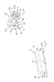
- Further characteristics and advantages of the present invention will become clearer from the indicative, and therefore non-limiting, description of a preferred but not exclusive embodiment of a food refrigeration apparatus, as illustrated in the accompanying drawings, in which:
-
figures 1 and 2 show perspective views of the refrigeration apparatus according to the present invention; -
figures 3 and 4 show two perspective views of a component of the refrigeration apparatus offigures 1 and 2 . - In the accompanying drawings, no. 1 indicates a refrigeration apparatus for food products.
- The
apparatus 1 comprises: - a refrigeration compartment 2 for foodstuffs;
- a door 3, movable between a closed position and an open position. In the closed position it opportunely obstructs access to said compartment 2 and in the open position it permits access to said compartment 2.
- The door 3 comprises a
first shelf 4 for positioning articles. In English technical jargon such a shelf is known as a "door shelf". In the closed position of the door 3 saidfirst shelf 4 faces said compartment 2 and/or it projects inside said compartment 2. - The door 3 comprises a back-
panel 31 to which thefirst shelf 4 is attached. In technical jargon the term "back-panel" is well-known. Usually the term is intended to mean a panel of the door 3 which in the closed position of the latter faces towards the compartment 2. - The
first shelf 4 comprises acover 40, movable between a closed configuration and an open configuration. In the open configuration thecover 40 allows access to the articles positioned on thefirst shelf 4; in the closed configuration thecover 40 prevents access by a user to articles placed on thefirst shelf 4. - The
apparatus 1 comprises locking means 5 for thecover 40 in said closed configuration. - The locking means 5 for example comprise a
protrusion 9 and a suitable housing 90 for retaining saidprotrusion 9. - Opportunely the locking means 5 are of snap type. This for example provides for an elastic deformation of the
protrusion 9 during engagement with and disengagement from said retaining housing 90. - The
apparatus 1 comprises unlocking means for said locking means 5. The unlocking means preferably are manually operable. The unlocking means are such as to minimise the risk of undesired unlocking of thecover 40. - For example the unlocking means could comprise two buttons which must be pressed simultaneously to unlock said locking means.
- In the preferred solution the locking means 5 and the unlocking means coincide. Opportunely the locking means 5 and the unlocking means comprise an ordinary lock.
- The
apparatus 1 comprises ahousing 41, delimited in combination by: - the
first shelf 4 with thecover 40 in the closed configuration; - a
first portion 32 of the back-panel 31. In the open configuration of saidcover 40 it is at least partially tilted with respect to its position in the closed configuration and overlaps with at least a part of thefirst portion 32 of the back-panel 31. In the closed configuration of thecover 40, saidfirst portion 32 of the back-panel 31 advantageously contributes to delimiting saidhousing 41 at least rearwards and/or upwards and/or laterally. Opportunely thefirst portion 32 of the back-panel 31 comprises an upper profile and two lateral profiles which project in relief and which contribute, in combination with theshelf 31, to delimiting saidhousing 41. - As exemplified in
figure 1 , the door 3 comprises a plurality ofshelves 400 attached to the back-panel 31. Thefirst shelf 4 is the shelf positioned highest compared with the remaining shelves of the back-panel 31. This presents a double advantage. On the one hand it enables a reduction in the possibilities of access to the contents of thefirst shelf 4 by children; on the other hand it makes it possible to exploit the geometry of the back-panel 31 which contributes to upwards delimiting thehousing 41. - The characteristics of the
first shelf 4 could also be applied to another shelf or other shelves attached to the back-panel. - Opportunely the
cover 40 is hinged and can rotate around afirst axis 30. In the open configuration thecover 40 is rotated around thefirst axis 30 with respect to its position in the closed configuration. - The
first shelf 4 opportunely comprises atray 42. Thetray 42 in its turn comprises: - a
front part 43 which is at least in part surmounted by thecover 40 in the closed configuration (preferably it is completely surmounted); - a
rear part 44. - The
cover 40 rests on therear part 44 in a configuration of maximum opening. - Front and rear are to be understood with reference to a user who with the door 3 open is facing the
first shelf 4. - The
cover 40 is advantageously hinged to thetray 42. Thecover 40 comprises: - a
first side 401 which in the closed configuration of thecover 40 is shielded by the front part of thetray 42; - a
second side 402 which in the closed configuration is shielded by thefirst portion 32 of the back-panel 31 and which in the maximum opening configuration rests on therear part 44 of thetray 42. - The
front part 43 of thetray 42 compriseslateral delimitation walls 45. - The
rear part 44 of thetray 42 compriseslateral delimitation walls 46. - The
rear part 44 of thetray 42 compriseslateral delimitation walls 46 which are higher than thelateral delimitation walls 45 of thefront part 43 of thetray 42; thefirst axis 30 of rotation of thecover 40 with respect to thetray 42 is higher than thedelimitation walls 46 of therear part 44; thefirst axis 30 of rotation of thecover 40 lies in proximity to a transition zone between thefront part 43 and therear part 44. Opportunely thefirst axis 30 of rotation of thecover 40 is substantially parallel to the first and/or to thesecond side tray 42 comprises two uprights to which thecover 40 is hinged. - Opportunely the
apparatus 1 comprises an ozoniser and/or anioniser 7 which emit particles (ozone or ions) having a purifying effect on the contents of the compartment 2 and/or on the air introduced into the compartment 2. - The active components of the ozoniser and/or of the
ioniser 7 are advantageously located in a housing fixed to the ceiling of the compartment 2 (for example to protect them from impacts and so as not to be immediately reachable by a user). These active components are furthermore in fluid communication with the compartment 2 through anopening 92 formed in a wall delimiting said housing. Theopening 92 is designed for introducing ozone, ions and air purified by the action of said ozoniser and/or of saidioniser 7 into the compartment. - The
cover 40 comprises at least onehole 91 which in the closed configuration of thecover 40 puts the inside of thefirst shelf 4 in fluid communication with said compartment 2. - As exemplified in the accompanying drawings the
cover 40 comprises a plurality of throughholes 91 which in the closed configuration of thecover 40 put the inside of thefirst shelf 4 in fluid communication with said compartment 2 (and therefore with the outside of the first shelf 4). Theholes 91 are preferably distributed along thecover 40 so as to affect an extended zone of thecover 40. In this connection the smallest area which without discontinuity encompasses all the holes has an area greater than or equal to 30% of a face of thecover 40 which in the closed configuration faces the outside of thefirst shelf 4. - Opportunely the smallest area which without discontinuity encompasses all the
holes 91 has an area greater than or equal to 30% of a surface of thefirst shelf 4 designed for bearing articles (i.e. the supporting surface). - Let a set be defined consisting of every
hole 91 which: - is formed in the
cover 40; and which - in the closed configuration of the
cover 40 puts the inside of thefirst shelf 4 in fluid communication with said compartment 2. - The set may coincide with a single hole or may comprise a plurality of through holes. The area given by the sum of all of the holes forming part of said set is greater than 20% of a face of the
cover 40 which in the closed configuration faces towards the outside of thefirst shelf 4. - The
holes 91 of said plurality of holes are organised along at least three side-by-side rows, each of said rows extending for at least 75% of the maximum width of the cover 40 (the maximum width of thecover 40 is measured along a direction parallel to thefirst axis 30 of rotation of the cover 40). - The
holes 91 of said plurality of holes preferably face upwards (i.e. face towards the opening 92 designed for introducing particles of ozone, ions and air purified by the action of said ozoniser and/or of said ioniser into the compartment 2). These expedients contribute to ensuring that the ozone and/or the ions with purifying and antibacterial action, coming from the ozoniser and/or the ioniser, can penetrate to the inside of thefirst shelf 4, but at the same time they enable the contents of thefirst shelf 4 to be protected from a direct flow of cold air. - The
cover 40 advantageously comprises more than thirtyholes 91. Thecover 40 is preferably made of an at least partially transparent material. In this way the user can look inside the first shelf without opening thecover 40. - The invention thus conceived enables multiple advantages to be attained.
- In particular this constructional solution makes it possible to create a
housing 41 in which products may be placed which must be kept at temperatures below ambient and which must be protected from accidental access by undesired users. For example a typical application could be the use of thehousing 41 as a medicine container in which the products are protected from undesired access by children. - The invention thus conceived is susceptible of numerous modifications and variants, all falling within the scope of the inventive concept characterising it. Furthermore all the details can be replaced by other technically equivalent elements. In practice, all the materials used, as well as the dimensions, can be any according to requirements.
- Still with reference by way of example to
figures 1-4 it is an object of the present invention to make available a foodstuff refrigeration apparatus which can be used for optimising hygiene inside the refrigeration apparatus, at the same time making it possible to protect such products from a direct flow of cold air. In the accompanying drawings, no. 1 indicates a refrigeration apparatus for food products. Therefrigeration apparatus 1 advantageously comprises a refrigerator or a fridge freezer. - The
apparatus 1 comprises: - a refrigeration compartment 2 for foodstuffs;
- a door 3, movable between a closed position and an open position. In the closed position it opportunely obstructs access to said compartment 2 and in the open position it permits access to said compartment 2.
- The door 3 comprises a
first shelf 4 for positioning articles. In English technical jargon such a shelf is known as a "door shelf". In the closed position of the door 3 saidfirst shelf 4 faces said compartment 2 and/or projects inside said compartment 2. - The
first shelf 4 comprises acover 40 movable between a closed configuration and an open configuration. In the open configuration thecover 40 allows access to the articles positioned on thefirst shelf 4. In the closed configuration thecover 40 prevents access by a user to articles placed on thefirst shelf 4. - Opportunely the
apparatus 1 comprises an ozoniser and/or anioniser 7 for emitting particles (ozone or ions) having a purifying effect on the contents of the compartment 2 and/or on the air introduced into the compartment 2. The door 3 comprises a back-panel 31 to which thefirst shelf 4 is attached. In technical jargon the term "back-panel" is well-known. Usually the term is intended to mean a panel of the door 3 which in the closed position of the latter faces towards the compartment 2. - The active components of the ozoniser and/or of the ioniser 7 (i.e. the purifying particle generators) are advantageously located in a housing fixed to the ceiling of the compartment 2 (for example to protect them from impacts and so as not to be immediately reachable by a user). These active components are in fluid communication with the compartment 2 through an
opening 92 formed in a wall delimiting said housing. Thisopening 92 is designed for introducing ozone, ions and/or air purified by the action of said ozoniser and/or of said ioniser into the compartment. - Opportunely said ozoniser and/or said
ioniser 7 is in fluid communication with anopening 92 formed in the ceiling of the compartment 2 and designed for introducing purifying particles and/or air purified by the action of said ozoniser and/orioniser 7 into the compartment 2. - The
cover 40 comprises at least onehole 91 which in the closed configuration of thecover 40 puts the inside of thefirst shelf 4 in fluid communication with said compartment 2 (or in any event with the outside of the first shelf 4). - As exemplified in the accompanying drawings the
cover 40 comprises a plurality of throughholes 91 which in the closed configuration of thecover 40 put the inside of thefirst shelf 4 in fluid communication with said compartment 2 (or at any rate with the outside of the first shelf 4). Theholes 91 are preferably distributed along thecover 40 so as to affect an extended zone of thecover 40. In this connection, advantageously the smallest area which without discontinuity encompasses all the holes has an area greater than or equal to 30% of the area of a face of thecover 40 which in the closed configuration faces towards the outside of thefirst shelf 4. - Opportunely the smallest area which without discontinuity encompasses all the
holes 91 has an area greater than or equal to 30% of a surface of thefirst shelf 4 designed for bearing articles (i.e. the supporting surface). - The
holes 91 are organised along at least three side-by-side rows, each of said rows extending for at least 75% of the maximum width of thecover 40. The width is measured along a direction parallel to anaxis 30 of rotation of thecover 40. As will be better explained below, in the preferred solution, to pass from the open configuration to the closed configuration, thecover 40 rotates around anaxis 30 of rotation. - The
holes 91 of said plurality of holes preferably face upwards (i.e. face towards the opening 92 designed for introducing air purified by the action of said ozoniser and/or of saidioniser 7 into the compartment). The above expedients contribute to ensuring that the particles (ozone and/or ions) with purifying and antibacterial action coming from the ozoniser and/or the ioniser can penetrate to the inside of thefirst shelf 4. At the same time these expedients make it possible to protect the contents of thefirst shelf 4 from a direct flow of cold air. - The
cover 40 advantageously comprises more than thirtyholes 91. Thecover 40 is preferably made of an at least partially transparent material. In this way the user can look inside the first shelf without opening thecover 40. - Let a set be defined consisting of every
hole 91 which is formed in thecover 40 and which in the closed configuration of thecover 40 puts the inside of thefirst shelf 4 into fluid communication with said compartment 2. - The set may coincide with the
first hole 91 or may also comprise said plurality of through holes. The area given by the sum of all of theholes 91 forming part of said set is greater than 20% of a face of thecover 40 which in the closed configuration faces the outside of thefirst shelf 4. - Advantageously the
apparatus 1 comprises locking means 5 for thecover 40 in said closed configuration. - The locking means 5 for example comprise a
protrusion 9 and an appropriate housing 90 for retaining saidprotrusion 9. - Opportunely the locking means 5 are of snap type. This for example provides for an elastic deformation of the
protrusion 9 during engagement with and disengagement from said retaining housing 90. - The
apparatus 1 comprises unlocking means for said locking means 5. The unlocking means are manually operable. The unlocking means are such as to minimise the risk of undesired unlocking of thecover 40. - For example (solution not illustrated) the unlocking means could comprise two buttons which must be pressed simultaneously to unlock said locking means. In the solution shown in the accompanying drawings, unlocking could be performed by overcoming the resistance offered by the locking means (at least a part of which can be elastically deformed to permit closure and opening).
- In the preferred solution the locking means 5 and the unlocking means could even coincide. Opportunely the locking means 5 and the unlocking means comprise an ordinary lock.
- The
apparatus 1 comprises ahousing 41 delimited in combination: - by the
first shelf 4 with thecover 40 in the closed configuration; - by a
first portion 32 of the back-panel 31. In the closed configuration of saidcover 40 it is at least partially tilted with respect to its position in the closed configuration and overlaps with at least a part of thefirst portion 32 of the back-panel 31. In the closed configuration of thecover 40 saidfirst portion 32 of the back-panel 31 advantageously contributes to delimiting saidhousing 41 at least rearwards and/or upwards and/or laterally. Opportunely thefirst portion 32 of the back-panel 31 comprises an upper profile and two lateral profiles which project in relief and which contribute, in combination with thefirst shelf 4, to delimiting saidhousing 41. - As exemplified in
figure 1 or 2 , the door 3 comprises a plurality ofshelves 400 attached to the back-panel 31. The first shelf is the shelf positioned highest compared with the remaining shelves of the back-panel. This presents a double advantage. On the one hand it enables a reduction in the possibilities of access to the contents of the first shelf by children; on the other hand it makes it possible to exploit the geometry of the back-panel which contributes to upwards delimiting thehousing 41. - The characteristics of the
first shelf 4 could also be applied to another shelf or other shelves attached to the back-panel 31. - Opportunely the
cover 40 is hinged and can rotate around theaxis 30 of rotation. In the open configuration thecover 40 is rotated around theaxis 30 of rotation with respect to its position in the closed configuration. - The
first shelf 4 opportunely comprises atray 42. Thetray 42 in its turn comprises: - a
front part 43 which in the closed configuration is at least in part surmounted by the cover 40 (preferably it is completely surmounted); - a
rear part 44 on which thecover 40 rests in a configuration of maximum opening; saidcover 40 being hinged to thetray 42. Front and rear are to be understood with reference to a user who with the door open is facing thefirst shelf 4. - The
cover 40 comprises: - a
first side 401 which in the closed configuration of thecover 40 is shielded by the front part of thetray 42; - a
second side 402 which in the closed configuration of thecover 40 is in proximity to (advantageously shielded by) saidfirst portion 32 of the back-panel 31 and which in the maximum opening configuration of thecover 40 rests on therear part 44 of thetray 42. - The
front part 43 of thetray 42 comprises lateral delimitationwalls 45. - The
rear part 44 of thetray 42 comprises lateral delimitationwalls 46. - The
rear part 44 of thetray 42 comprises lateral delimitationwalls 46 which are higher than lateral delimitationwalls 45 of thefront part 43 of thetray 42; the axis of rotation of thecover 40 with respect to thetray 42 is higher than the delimitationwalls 46 of therear part 44; the axis of rotation of thecover 40 lies in proximity to a transition zone between thefront part 43 and therear part 44. Opportunely theaxis 30 of rotation of thecover 40 is parallel to the first and/or to thesecond side tray 42 comprises two uprights to which thecover 40 is hinged. The invention thus conceived enables multiple advantages to be attained. - In particular this constructional solution allows the particles emitted by the ozoniser/ioniser to also affect products placed inside said
first shelf 4, protecting them at least partially from contact with a cold air flow. - The invention thus conceived is susceptible of numerous modifications and variants, all falling within the scope of the inventive concept characterising it. Furthermore all the details can be replaced by other technically equivalent elements. In practice, all the materials used, as well as the dimensions, can be any according to requirements.
Claims (15)
- A refrigeration apparatus for food products comprising:- a refrigeration compartment (2) for foodstuffs;- a door (3) movable between a closed position and an open position; said door (3) comprising a first shelf (4) for positioning articles; in the closed position of the door (3), said first shelf (4) facing said compartment (2) and/or projecting inside said compartment (2); said first shelf (4) comprising a cover (40) movable between a closed configuration and an open configuration;characterised by comprising locking means (5) for the cover (40) in said closed configuration.
- The apparatus according to claim 1, characterised in that the locking means (5) are of snap type.
- The apparatus according to claim 1 or 2, characterised by comprising unlocking means for said locking means (5), said unlocking means being manually operable.
- The apparatus according to claim 3, characterised in that said locking means (5) and said unlocking means comprise an ordinary lock.
- The apparatus according to any one of the preceding claims, characterised in that the door (3) comprises a back-panel (31) and a plurality of shelves (400) attached to the back-panel (31), said first shelf (4) being the shelf located highest compared with the other shelves (400) attached to the back-panel (31).
- The apparatus according to claim 5, characterised by featuring a housing (41) delimited in combination:- by the first shelf (4) with the cover (40) in the closed configuration;- by a first portion (32) of the back-panel (31); in the open configuration said cover (40) being at least partially tilted with respect to the closed configuration and overlapping with said first portion (32) of the back-panel (31); in the closed configuration of the cover (40) said first portion (32) of the back-panel (31) contributing to delimiting said housing (41) at least upwards and rearwards.
- The apparatus according to any one of the preceding claims, characterised in that the cover (40) is hinged and can rotate around a first axis (30), in the open configuration the cover (40) being rotated around the first axis (30) with respect to the position in the closed configuration.
- The apparatus according to any one of the preceding claims, characterised in that the first shelf (4) comprises a tray (42) which in its turn comprises:- a front part (43) which is at least in part surmounted by the cover (40) in the closed configuration;- a rear part (44) on which the cover (40) rests in a configuration of maximum opening; said cover (40) being hinged to the tray (42).
- The apparatus according to claim 8, characterised in that the cover (40) comprises:- a first side (401) which in the closed configuration of the cover (40) is shielded by the front part (43) of the tray (42);- a second side (402) which in the closed configuration is shielded by the first portion (32) of the back-panel (31) and which in the configuration of maximum opening rests on the rear part (44) of the tray (42).
- The apparatus according to claim 8 or 9 when it depends directly or indirectly on claim 7, characterised in that:- the front part (43) of the tray (42) comprises lateral delimitation walls (45).- the rear part (44) of the tray (42) comprises lateral delimitation walls (46);the lateral delimitation walls (46) of the rear part (44) are higher than the lateral delimitation walls (45) of the front part (43) of the tray (42); the first axis (30) of rotation of the cover (40) with respect to the tray (42) being situated higher than the delimitation walls (46) of the rear part (44); the first axis (30) of rotation of the cover (40) lying in proximity to a transition zone between the front part (43) and the rear part (44).
- The apparatus according to any one of the preceding claims, characterised by comprising an ozoniser and/or an ioniser (7) for introducing particles having a purifying effect on the contents of the compartment (2) and/or on the air introduced into the compartment (2); said cover (40) comprising at least one hole (91) which in the closed configuration of the cover (40) puts the inside of the first shelf (4) in fluid communication with said compartment (2).
- The apparatus according to claim 11, characterised in that the cover (40) comprises a plurality of through holes (91) which in the closed configuration of the cover (40) put the inside of the first shelf (4) in fluid communication with said compartment (2);- the smallest area which without discontinuity encompasses all the holes has an area greater than or equal to 30% of a face of the cover (40) which in the closed configuration faces towards the outside of the first shelf (4); or- the smallest area which without discontinuity encompasses all the holes (91) has an area greater than or equal to 30% of a surface of the first shelf (4) designed for bearing articles.
- The apparatus according to claim 11 or 12, wherein a set is defined consisting of every hole (91) which:- is formed in the cover (40);- in the closed configuration of the cover (40) puts the inside of the first shelf (4) in fluid communication with said compartment (2);said apparatus being characterised in that the area given by the sum of all the holes (91) forming part of said set is greater than 20% of the area of a face of the cover (40) which in the closed configuration faces towards the outside of the first shelf (4).
- The apparatus according to any one of claims 11 to 13, characterised in that said ozoniser and/or ioniser (7) is in fluid communication with an opening (92) formed in the ceiling of the compartment (2) and designed for introducing purifying particles and/or air purified by the action of said ozoniser and/or ioniser (7) into the compartment (2).
- A refrigeration apparatus for food products comprising:- a refrigeration compartment (2) for foodstuffs;- a door (3) movable between a closed position and an open position; said door (3) comprising a first shelf (4) for positioning articles; in the first position of the door (3) said first shelf (4) facing said compartment (2) and/or projecting inside said compartment (2); said first shelf (4) comprising a cover (40) movable between a closed configuration and an open configuration;- an ozoniser and/or an ioniser (7) for introducing particles having a purifying effect on the contents of the compartment (2) and/or on the air introduced into the compartment (2);characterised in that said cover (40) comprises at least one hole (91) which in the closed configuration of the cover (40) puts the inside of the first shelf (4) in fluid communication with said compartment (2).
Applications Claiming Priority (2)
| Application Number | Priority Date | Filing Date | Title |
|---|---|---|---|
| ITPR20120004 ITPR20120004U1 (en) | 2012-09-27 | 2012-09-27 | REFRIGERATION APPARATUS. |
| ITPR20120003 ITPR20120003U1 (en) | 2012-09-27 | 2012-09-27 | FOOD REFRIGERATION APPARATUS. |
Publications (2)
| Publication Number | Publication Date |
|---|---|
| EP2713123A2 true EP2713123A2 (en) | 2014-04-02 |
| EP2713123A3 EP2713123A3 (en) | 2017-08-30 |
Family
ID=49301279
Family Applications (1)
| Application Number | Title | Priority Date | Filing Date |
|---|---|---|---|
| EP13185669.2A Withdrawn EP2713123A3 (en) | 2012-09-27 | 2013-09-24 | Refrigeration apparatus for food products |
Country Status (1)
| Country | Link |
|---|---|
| EP (1) | EP2713123A3 (en) |
Family Cites Families (3)
| Publication number | Priority date | Publication date | Assignee | Title |
|---|---|---|---|---|
| KR100767844B1 (en) * | 2006-07-11 | 2007-10-17 | 엘지전자 주식회사 | Refrigerator |
| WO2010114186A1 (en) * | 2009-04-01 | 2010-10-07 | Lg Electronics Inc. | Refrigerator having ice making device |
| KR20100118435A (en) * | 2009-04-28 | 2010-11-05 | 삼성전자주식회사 | Door guard assembly and refrigerator having the same |
-
2013
- 2013-09-24 EP EP13185669.2A patent/EP2713123A3/en not_active Withdrawn
Non-Patent Citations (1)
| Title |
|---|
| None |
Also Published As
| Publication number | Publication date |
|---|---|
| EP2713123A3 (en) | 2017-08-30 |
Similar Documents
| Publication | Publication Date | Title |
|---|---|---|
| EP3954954B1 (en) | Refrigerator | |
| EP3244148B1 (en) | Refrigerator | |
| US12349789B2 (en) | Undercounter refrigerator with access control | |
| KR101624822B1 (en) | Goods take-out port structure for vending machine | |
| JP2011069612A (en) | Refrigerator with double storage door | |
| EP2525177B1 (en) | A display chiller | |
| CN102782428B (en) | There is the refrigerating appliance of the packing compartments of belt sliding door | |
| US10151525B2 (en) | Harvest bin assembly | |
| EP3132214B1 (en) | Refrigerator | |
| US20140139088A1 (en) | Transparent touch displays for refrigerator drawers | |
| KR20180062122A (en) | Refrigerator | |
| US8608263B2 (en) | Beverage container storage and dispensing compartment for a refrigerator | |
| KR101446346B1 (en) | Door baskets for refrigerator | |
| EP2655991B1 (en) | A refrigerator | |
| KR102297099B1 (en) | Storage of spices and vegetables Refrigerator | |
| KR100488526B1 (en) | Refrigerator | |
| KR20170109940A (en) | Refrigerator | |
| DK179181B1 (en) | Freezer insert with forced convection | |
| US10508857B2 (en) | Home appliance device | |
| WO2012126705A2 (en) | Refrigerator comprising a sliding storage box | |
| KR20160044233A (en) | Refrigerator | |
| KR101717685B1 (en) | Rotation type tray structure for refrigeration | |
| WO2009127534A3 (en) | Storage compartment for cooled material | |
| KR100679649B1 (en) | Side dish storage unit of the refrigerator | |
| GB2367117A (en) | Refrigeration display cabinets |
Legal Events
| Date | Code | Title | Description |
|---|---|---|---|
| PUAI | Public reference made under article 153(3) epc to a published international application that has entered the european phase |
Free format text: ORIGINAL CODE: 0009012 |
|
| AK | Designated contracting states |
Kind code of ref document: A2 Designated state(s): AL AT BE BG CH CY CZ DE DK EE ES FI FR GB GR HR HU IE IS IT LI LT LU LV MC MK MT NL NO PL PT RO RS SE SI SK SM TR |
|
| AX | Request for extension of the european patent |
Extension state: BA ME |
|
| RAP1 | Party data changed (applicant data changed or rights of an application transferred) |
Owner name: WHIRLPOOL EMEA S.P.A |
|
| RIC1 | Information provided on ipc code assigned before grant |
Ipc: F25D 23/04 20060101AFI20170404BHEP |
|
| PUAL | Search report despatched |
Free format text: ORIGINAL CODE: 0009013 |
|
| AK | Designated contracting states |
Kind code of ref document: A3 Designated state(s): AL AT BE BG CH CY CZ DE DK EE ES FI FR GB GR HR HU IE IS IT LI LT LU LV MC MK MT NL NO PL PT RO RS SE SI SK SM TR |
|
| AX | Request for extension of the european patent |
Extension state: BA ME |
|
| RIC1 | Information provided on ipc code assigned before grant |
Ipc: F25D 23/04 20060101AFI20170725BHEP |
|
| STAA | Information on the status of an ep patent application or granted ep patent |
Free format text: STATUS: THE APPLICATION HAS BEEN PUBLISHED |
|
| STAA | Information on the status of an ep patent application or granted ep patent |
Free format text: STATUS: THE APPLICATION IS DEEMED TO BE WITHDRAWN |
|
| 18D | Application deemed to be withdrawn |
Effective date: 20180301 |