EP2713051B1 - A turbine-driven reciprocating compressor and method of operating said compressor - Google Patents
A turbine-driven reciprocating compressor and method of operating said compressor Download PDFInfo
- Publication number
- EP2713051B1 EP2713051B1 EP13186433.2A EP13186433A EP2713051B1 EP 2713051 B1 EP2713051 B1 EP 2713051B1 EP 13186433 A EP13186433 A EP 13186433A EP 2713051 B1 EP2713051 B1 EP 2713051B1
- Authority
- EP
- European Patent Office
- Prior art keywords
- turbine
- reciprocating compressor
- barring
- gearbox
- clutch
- Prior art date
- Legal status (The legal status is an assumption and is not a legal conclusion. Google has not performed a legal analysis and makes no representation as to the accuracy of the status listed.)
- Active
Links
Images

Classifications
-
- F—MECHANICAL ENGINEERING; LIGHTING; HEATING; WEAPONS; BLASTING
- F01—MACHINES OR ENGINES IN GENERAL; ENGINE PLANTS IN GENERAL; STEAM ENGINES
- F01D—NON-POSITIVE DISPLACEMENT MACHINES OR ENGINES, e.g. STEAM TURBINES
- F01D15/00—Adaptations of machines or engines for special use; Combinations of engines with devices driven thereby
- F01D15/08—Adaptations for driving, or combinations with, pumps
-
- F—MECHANICAL ENGINEERING; LIGHTING; HEATING; WEAPONS; BLASTING
- F01—MACHINES OR ENGINES IN GENERAL; ENGINE PLANTS IN GENERAL; STEAM ENGINES
- F01D—NON-POSITIVE DISPLACEMENT MACHINES OR ENGINES, e.g. STEAM TURBINES
- F01D15/00—Adaptations of machines or engines for special use; Combinations of engines with devices driven thereby
- F01D15/12—Combinations with mechanical gearing
-
- F—MECHANICAL ENGINEERING; LIGHTING; HEATING; WEAPONS; BLASTING
- F02—COMBUSTION ENGINES; HOT-GAS OR COMBUSTION-PRODUCT ENGINE PLANTS
- F02C—GAS-TURBINE PLANTS; AIR INTAKES FOR JET-PROPULSION PLANTS; CONTROLLING FUEL SUPPLY IN AIR-BREATHING JET-PROPULSION PLANTS
- F02C7/00—Features, components parts, details or accessories, not provided for in, or of interest apart form groups F02C1/00 - F02C6/00; Air intakes for jet-propulsion plants
- F02C7/36—Power transmission arrangements between the different shafts of the gas turbine plant, or between the gas-turbine plant and the power user
-
- F—MECHANICAL ENGINEERING; LIGHTING; HEATING; WEAPONS; BLASTING
- F04—POSITIVE - DISPLACEMENT MACHINES FOR LIQUIDS; PUMPS FOR LIQUIDS OR ELASTIC FLUIDS
- F04B—POSITIVE-DISPLACEMENT MACHINES FOR LIQUIDS; PUMPS
- F04B35/00—Piston pumps specially adapted for elastic fluids and characterised by the driving means to their working members, or by combination with, or adaptation to, specific driving engines or motors, not otherwise provided for
- F04B35/006—Piston pumps specially adapted for elastic fluids and characterised by the driving means to their working members, or by combination with, or adaptation to, specific driving engines or motors, not otherwise provided for driven by steam engines
-
- F—MECHANICAL ENGINEERING; LIGHTING; HEATING; WEAPONS; BLASTING
- F04—POSITIVE - DISPLACEMENT MACHINES FOR LIQUIDS; PUMPS FOR LIQUIDS OR ELASTIC FLUIDS
- F04B—POSITIVE-DISPLACEMENT MACHINES FOR LIQUIDS; PUMPS
- F04B35/00—Piston pumps specially adapted for elastic fluids and characterised by the driving means to their working members, or by combination with, or adaptation to, specific driving engines or motors, not otherwise provided for
- F04B35/01—Piston pumps specially adapted for elastic fluids and characterised by the driving means to their working members, or by combination with, or adaptation to, specific driving engines or motors, not otherwise provided for the means being mechanical
-
- F—MECHANICAL ENGINEERING; LIGHTING; HEATING; WEAPONS; BLASTING
- F04—POSITIVE - DISPLACEMENT MACHINES FOR LIQUIDS; PUMPS FOR LIQUIDS OR ELASTIC FLUIDS
- F04B—POSITIVE-DISPLACEMENT MACHINES FOR LIQUIDS; PUMPS
- F04B35/00—Piston pumps specially adapted for elastic fluids and characterised by the driving means to their working members, or by combination with, or adaptation to, specific driving engines or motors, not otherwise provided for
Definitions
- Embodiments of the present disclosure generally relate to reciprocating compressor systems and more specifically to reciprocating compressor systems driven by turbines, such as steam turbines.
- Reciprocating compressors are commonly used in the industry for compressing gases in a wide range of applications. Reciprocating compressors are usually driven by a prime mover, which can be an electric motor, a reciprocating internal combustion engine or a gas or steam turbine.
- a prime mover which can be an electric motor, a reciprocating internal combustion engine or a gas or steam turbine.
- Fig. 1 illustrates a prior art arrangement 1 comprising a reciprocating compressor system, comprising a compressor 3, and a steam turbine 5 used to drive the reciprocating compressor 3.
- the reciprocating compressor 3 comprises a plurality of compressor cylinders 3A, 3B, 3C and 3D.
- a common crankshaft 7 drives the four reciprocating compressor cylinders 3A-3D and supports a flywheel (not shown).
- the crankshaft 7 is rotatingly supported in a casing 9 and is driven into rotation by the steam turbine 5 through a gearbox 11 having an inlet shaft 13 and an outlet shaft 15.
- the inlet shaft 13 (high speed coupling) rotates at the rotary speed of the steam turbine 5, while the output driven shaft 15 (low speed coupling), which connects the gearbox 11 to the crankshaft 7, rotates at a substantially lower rotational speed.
- the crankshaft 7 is usually supported by hydrodynamic bearings 17. Correct operation of hydrodynamic bearings is dependent upon the speed between mutually moving parts, e.g. a fixed bushing and a rotary member, such as a pin or shaft. A lubrication oil film develops between the moving components when a sufficient speed is achieved. Lubrication of other components and parts of reciprocating compressor is also dependent upon the operation speed of the compressor, for instance lubrication of crossheads and runners, piston rods and the like.
- shafts in the gearbox 11 can be supported by hydrodynamic bearings and require to rotate at a speed sufficient to generate a lubrication oil film, to prevent bearing damages.
- the system 1 therefore further comprises a slow turning motor 19, also referred to as "barring motor” or “barring device”.
- the barring motor 19 is usually an electric motor, which can be selectively connected to and disconnected from the rotor of the steam turbine 5 when requested.
- the barring motor 19 must therefore have a rated power sufficient to overcome the high inertia of the train and the high breakaway torque. The rated power of the barring motor 19 is therefore much higher than the power which would be required to turn just the rotor of the steam turbine.
- the barring speed is insufficient to develop a lubrication oil film in the hydrodynamic bearings, and therefore during slow turning of the turbine the bearings operate in a boundary lubrication condition involving high wear rate.
- Embodiments disclosed herein alleviate or overcome one or more of the abovementioned problems of prior art reciprocating compressor systems driven by a turbine.
- a reciprocating compressor system comprising a turbine and at least one reciprocating compressor driven by the turbine.
- the turbine is a steam turbine.
- a gearbox can be provided in the system and is arranged between the turbine and the reciprocating compressor.
- a clutch is provided, between the turbine and the reciprocating compressor, for mechanically disconnecting the turbine from the reciprocating compressor during a transient phase of operation of the system, for example during a barring phase or during a turbine warm-up phase.
- a barring device is further provided for slow-turning the turbine during a barring phase.
- the system can comprise a reciprocating compressor section comprising at least one reciprocating compressor with one or more compressor cylinders and a common crankshaft driving the pistons of the compressor cylinders.
- the crankshaft is usually supported by hydrodynamic bearings.
- the clutch can be disengaged for example upon shutdown of the turbine.
- the reciprocating compressor remains then stationary while the turbine is slow-turned at a barring rotary speed, to prevent bowing of the turbine rotor during cooling.
- the barring speed can be set at a very low value, since failures of the reciprocating compressor bearings due to insufficient rotary speed of the hydrodynamic bearings will not occur, as the reciprocating compressor is inoperative.
- the barring device can thus be designed to provide limited power, thus reducing the costs and dimension of the barring device.
- the clutch can be arranged and controlled for performing a transient phase comprising warm-up of the turbine.
- the turbine can then be rotated steadily and continuously at one or more warm-up speeds, which can be equal or near to one or more critical speeds of the shaft line.
- the turbine being disengaged from the remaining shaft line, resonance phenomena of the system are prevented.
- the turbine can be maintained at a rotary speed near to or coinciding with one or more torsional natural frequencies of the train, i.e. the system comprised of the various components driven by the turbine.
- the clutch can be arranged between the output shaft (low speed coupling) of the gearbox and the crankshaft of the reciprocating compressor. In currently preferred embodiments, however, the clutch is arranged between the turbine and the input shaft (high speed coupling) of gearbox. When the clutch is disengaged, the gearbox as well as the reciprocating compressor can be maintained stationary, while the turbine is operated in a transient condition, e.g. during barring or warm-up.
- the clutch is externally operated, e.g. by a suitable actuator.
- the clutch is a self-synchronizing clutch.
- the barring device can be comprised of an actuator, such as for example an electric motor or a hydraulic device.
- a barring gear or gear box can be provided between the actuator and the turbine rotor.
- a clutch can be provided for separating the barring device from the turbine rotor when the turbine is operating.
- the system can be a dual-drive system.
- the reciprocating compressor can be driven at an operative speed, which is different (e.g. higher) than the speed that would be provided by the slow-turning turbine, e.g. by means of a secondary mover, for instance an electric motor or a reversible electric machine.
- a reversible electric machine is a machine capable of being operated in a motor mode or in a generator mode. When a reversible electric machine is used, it can be driven by the turbine and operate in the generator mode when the turbine is in operative, steady-state conditions. If mechanical power is generated by the turbine in excess with respect to the power needed to drive the reciprocating compressor(s), the excess mechanical power can be converted into electric power and used to power facilities combined with the reciprocating compressor system and/or transferred to an electric distribution grid.
- the electric machine can be arranged on a side-shaft engageable to or disengageable from the main shaft line.
- the electric machine can be arranged on a side-shaft permanently engaged with the main shaft line, e.g. through a gearbox.
- the electric machine comprises a through shaft with a first end and a second end, permanently engaged to the main shaft line connecting the turbine and the reciprocating compressor.
- the electric machine can be arranged between the gearbox and the crankshaft of the reciprocating compressor.
- a method of operating a turbine-driven reciprocating compressor system comprises a step of mechanically disengaging the turbine from at least one reciprocating compressor and operating the system in at least one transient condition, with the turbine rotating at a speed different from the steady-state rotary speed or rotary speed range.
- the method comprises rotating the turbine by means of a barring device at a barring speed below an operative speed range after shutdown of said turbine, and/or in a direction opposite to the normal rotation direction of the turbine.
- the method comprises the step of mechanically disengaging the turbine from a gearbox arranged between the turbine and the reciprocating compressor when the system is performing a transient phase, such as a barring phase.
- the method can comprise the steps of:
- the reciprocating compressor at shutdown of the turbine, can be maintained in operative conditions by driving the reciprocating compressor with a second mover.
- a method comprising the steps of:
- a method comprising the steps of:
- the following exemplary embodiments of the subject matter disclosed herein include a steam turbine. At least some of the advantages of the disclosure can be achieved also with a system using a different turbine, e.g. a gas turbine.
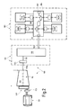
- a system 101 comprising a reciprocating compressor 103.
- the reciprocating compressor 103 can comprise a reciprocating compressor arrangement including one or more compressor cylinders and relevant pistons, driven by a common prime mover, as will be disclosed here below.
- the reciprocating compressor 103 comprises four compressor cylinders labeled 103A, 103B, 103C, 103D.
- a different number of reciprocating compressors or a different number of compressor cylinders can be provided.
- a crankshaft 105 drives the compressor pistons arranged in the compressor cylinders 103A-103D of the reciprocating compressor 103.
- the crankshaft 105 can be supported by bearings 107, 109, 111 schematically illustrated in Fig. 2 .
- the bearings 107, 109 and 111 can be hydrodynamic bearings, wherein a lubrication-oil hydrodynamic film develops when the crankshaft 105 rotates at a sufficiently high rotational speed.
- the system 101 further comprises a turbine 115, e.g. a steam turbine.
- the steam turbine 115 is the prime mover, which turns the crankshaft 105 and drives the reciprocating movement of the pistons and of the cross-heads (not shown) of the compressor cylinders 103A-103D in the reciprocating compressor 103.
- the steam turbine 115 is connected to the crankshaft 105 through a mechanical link labeled 117 as a whole.
- the mechanical link or connection 117 comprises a gearbox 119, with an input shaft, or high speed coupling 121, and an output shaft, or low speed coupling 123.
- the gearbox 119 can be an epicyclical gearbox, to reduce the rotary speed of the steam turbine 115 to the relatively low rotary speed of the crankshaft 105.
- the clutch 125 can be a self-synchronizing clutch. In other embodiments the clutch 125 can be externally operated, for example by means of a suitable actuator, not shown.
- a self-synchronizing clutch is configured so that the clutch is automatically engaged once the input shaft thereof achieves a given speed value. Conversely, the clutch automatically disengages when the speed of the input shaft drops below a given speed value or is reversed.
- Self-synchronizing clutches are known to those skilled in the art and require no detailed description. With a self-synchronizing clutch 125 the steam turbine output shaft 115A will be coupled to the input shaft 121 of the gearbox 119 only when the steam turbine has reached a certain rotary speed. Below that speed, and in case of reversal rotation of the steam turbine rotor, the clutch 125 disengages the output shaft 115A of the turbine 115 from the input shaft 121 of the gearbox 119.
- reference number 126 schematically indicates the rotor shaft of the steam turbine 115.
- the rotor shaft 126 can be drivingly connected to a barring gear 129.
- the barring gear 129 can be selectively connected to and disconnected from a barring device or slow turning device 131.
- the slow turning device or barring device 131 is comprised of an electric motor.
- a selectively engageable and disengageable clutch 133 can be provided between the barring device 131 and the barring gear 129.
- the clutch 125 is advantageously disengaged.
- the shaft line downstream of the clutch 125 thus remains stationary, while the steam turbine rotor is maintained at a slow-turning barring condition.
- the direction of rotation during slow-turning can be reversed with respect to the normal operating rotary speed.
- the barring device 131 can therefore be designed to developed a torque sufficient to drive into rotation the rotor of the steam turbine 115 only, without having to drive into rotation the remaining part of the shaft line. Since both the gearbox 119 as well as the reciprocating compressor 103 are disengaged from the output shaft 115A of the steam turbine 115, no hydrodynamic support is required from the bearings of the gearbox 119 and of the crankshaft 105. Lubrication of the remaining components of the reciprocating compressor is also not required. Slow turning of the steam turbine 115 will not damage the bearings and mechanical components of the system arranged downstream of the clutch 125.
- the clutch 125 interposed between the steam turbine 115 and the gearbox 119 also allows the steam turbine 115 to be rotate during barring in a direction opposite the operative rotary speed of the system, if desired.
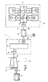
- Fig.3 schematically illustrates another exemplary embodiment of the present disclosure.
- the same reference numbers are used to designate the same or similar components as in Fig.2 . These components will not be described again.
- the embodiment of Fig.3 comprises a dual-drive reciprocating compressor arrangement, wherein the reciprocating compressor 103, including compressor cylinders 103A-103D, can be driven selectively by the prime mover including the steam turbine 115 or by a secondary mover, including an electric machine 128.
- the electric machine 128 is a reversible electric machine.
- the reversible electric machine 128 can operate alternatively to convert electric power into mechanical power (motor mode), or to convert mechanical power into electric power (generator mode).
- the reversible electric machine 128 is electrically connected to an electric distribution grid, schematically shown at G. Electric power conditioning devices and circuits, not shown, can be provided between the electric machine and the grid.
- the reversible electric machine 128 has a through shaft 130 with opposing ends connected, e.g. via joints 130A and 130B, to the output shaft 123 of the gearbox 119 and to the crankshaft 105 of the reciprocating compressor 103, respectively.
- the reciprocating compressor 103 can be driven alternatively by the reversible electric machine 128 or by the steam turbine 115.
- the clutch 125 can be disengaged and the steam turbine 115 can be maintained inoperative or can be rotated at a slow barring speed or a slow warm-up speed.
- the steam turbine 115 can be shutdown and brought into barring conditions, while the reciprocating compressor 103 continues operating by means of the reversible electric machine 128.
- the steam turbine can be rotated at a below-rated speed until a required temperature regime has been reached, while the reciprocating compressor 103 is driven by the electric machine.
- the operating conditions of the steam turbine 115 are thus made to some extent independent from the operating conditions of the reciprocating compressor 103.
- the steam turbine 115 can be run at design conditions maximizing the efficiency of the thermodynamic cycle, irrespective of fluctuations in the operative conditions of the reciprocating compressor 103. Excess mechanical power generated by the steam turbine 115 is converted in useful electric power.
- the electric machine 128 can operate only as an electric motor and will rotate idly when the reciprocating compressor 103 is driven by the steam turbine 115.
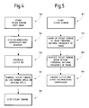
- Fig. 4 schematically illustrates a method of operating the system 101 in a transient phase involving steam turbine 115 shutdown.
- the shutdown process starts at 150.
- the reciprocating compressor 103 and the gearbox 119 are stopped (step 151) and the clutch 125 is disengaged (step 153), thus mechanically separating the steam turbine 115 from the gearbox 119 and the reciprocating compressor 103.
- slow turning (barring) of the steam turbine 115 by means of barring motor 131 and barring gear 121 can start (step 154) and will continue until the steam turbine 115 has cooled down to a temperature sufficient to avoid bowing or thermal deformation of the steam turbine rotor. Once these conditions are reached, the steam turbine can be stopped (step 155).
- Fig. 5 illustrates the method of operating the system 101 during a transient phase involving start-up of the steam turbine 115.
- the steam turbine 115 can be driven at a gradually increasing rotary speed from zero up to the rated rotary speed. Speeding up of the steam turbine 115 can be stepwise or continuous. In some embodiments, intermediate transient rotary speeds can be maintained for a certain period of time to allow the steam cycle to smoothly achieve the final steady state operative conditions.
- the shaft line or train formed by steam turbine 115, gearbox 119, reciprocating compressor 103 with crankshaft 105, relevant crossheads, pistons, and reversible electric machine is characterized by one or more torsional natural frequencies (critical speeds), which are usually lower than the frequency at the rated rotary speed of the system. This means that during warm-up of the steam turbine 115 the turbine shaft will rotate at a gradually increasing speed moving through the torsional natural frequencies of the system.
- Fig. 5 summarizes the method of operating the system 101 during a transient process from start-up of the steam turbine 115 up to steady-state conditions.
- the steam turbine 115 is started.
- a subsequent warm-up step 162 follows, during which the steam turbine 115 can rotate at nearly the torsional natural frequency of the train.
- Clutch 125 is disengaged.
- the gearbox 119, the reversible electric machine 128 (if present) and the reciprocating compressor 103 are at standstill.
- step 163 the steam turbine speed is increased beyond the torsional natural frequencies of the train and finally, at step 164, the clutch 125 is engaged and the reciprocating compressor 103 starts operating.
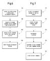
- Fig.6 illustrates a method of turbine startup according to a further embodiment of the present disclosure, using a dual-drive system according to Fig.3 , for instance.
- the first step of the startup process (step 165) comprises starting the electric machine 128 in the motor mode and driving the reciprocating compressor 103. While the clutch 125 is maintained in a disengaged condition, the steam turbine 115 can initiate a warm-up phase.
- the warm-up phase can start before, during or after start-up of the electric machine 128 and of the reciprocating compressor 103.
- warm-up starts step 166) after start-up of the secondary mover. This, however, is not mandatory.
- the rotary speed of the steam turbine can then gradually increase (step 167) until a rated speed is achieved, upon which the clutch 125 can be engaged.
- the electric machine (secondary mover) 128 can be shut down or switched to the generator mode (step 168).
- the reciprocating compressor 103 can thus be started and gradually accelerated to the rated speed avoiding running the reciprocating compressor 103 under no-load conditions for too long, a situation which could result in mechanical failures.
- the steam turbine 115 can run in a transient warm-up condition and the speed thereof can be increased following an optimal speed sequence, without influencing the operation of the reciprocating compressor 103. Only once the rated rotary speed of the steam turbine 115 has been reached, the steam turbine takes up the task of driving the reciprocating compressor 103.
- Fig. 7 illustrates a flowchart showing an embodiment of a further method of operating the system 101 during a transient phase. More specifically, Fig.7 illustrates a steam turbine shut-down procedure in a dual-drive system, for instance as shown in Fig.3 .
- the shut-down method of Fig.7 is aimed at shutting down the steam turbine 115 maintaining the reciprocating compressor 113 in operation.
- the secondary mover comprising the electric machine 128 is started and rotated at a rated speed (step 171).
- Shut-down of the steam turbine 115 is then started (step 172) and the clutch 125 is disengaged (step 173).
- a slow-turning or barring step of the steam turbine 115 follows (step 174), until the steam turbine 115 finally stops (step 175).
- the reciprocating compressor 103 continues operating, being driven by the secondary mover 128.
Landscapes
- Engineering & Computer Science (AREA)
- Mechanical Engineering (AREA)
- General Engineering & Computer Science (AREA)
- Chemical & Material Sciences (AREA)
- Combustion & Propulsion (AREA)
- Compressors, Vaccum Pumps And Other Relevant Systems (AREA)
- Control Of Turbines (AREA)
- Structures Of Non-Positive Displacement Pumps (AREA)
Description
- Embodiments of the present disclosure generally relate to reciprocating compressor systems and more specifically to reciprocating compressor systems driven by turbines, such as steam turbines.
- Reciprocating compressors are commonly used in the industry for compressing gases in a wide range of applications. Reciprocating compressors are usually driven by a prime mover, which can be an electric motor, a reciprocating internal combustion engine or a gas or steam turbine.
-
Fig. 1 illustrates aprior art arrangement 1 comprising a reciprocating compressor system, comprising acompressor 3, and asteam turbine 5 used to drive the reciprocatingcompressor 3. InFig. 1 thereciprocating compressor 3 comprises a plurality ofcompressor cylinders common crankshaft 7 drives the fourreciprocating compressor cylinders 3A-3D and supports a flywheel (not shown). Thecrankshaft 7 is rotatingly supported in acasing 9 and is driven into rotation by thesteam turbine 5 through agearbox 11 having aninlet shaft 13 and anoutlet shaft 15. The inlet shaft 13 (high speed coupling) rotates at the rotary speed of thesteam turbine 5, while the output driven shaft 15 (low speed coupling), which connects thegearbox 11 to thecrankshaft 7, rotates at a substantially lower rotational speed. - The
crankshaft 7 is usually supported byhydrodynamic bearings 17. Correct operation of hydrodynamic bearings is dependent upon the speed between mutually moving parts, e.g. a fixed bushing and a rotary member, such as a pin or shaft. A lubrication oil film develops between the moving components when a sufficient speed is achieved. Lubrication of other components and parts of reciprocating compressor is also dependent upon the operation speed of the compressor, for instance lubrication of crossheads and runners, piston rods and the like. - Also the shafts in the
gearbox 11 can be supported by hydrodynamic bearings and require to rotate at a speed sufficient to generate a lubrication oil film, to prevent bearing damages. - When the
steam turbine 5 is shut down, thesteam turbine 5 must be kept rotating at low turning speed in order to prevent bowing deformations and bending of the turbine rotor due to thermal gradients inside the turbine. Non-uniform temperature fields inside the turbine arise upon shutdown, since the lower portions of the turbine cool faster than the upper portions. To prevent bowing of the turbine rotor, the latter is maintained in a slow turning condition. This phase of the turbine operation is usually referred as "barring". - The
system 1 therefore further comprises aslow turning motor 19, also referred to as "barring motor" or "barring device". Thebarring motor 19 is usually an electric motor, which can be selectively connected to and disconnected from the rotor of thesteam turbine 5 when requested. During barring of thesteam turbine 5 the whole shaft line, i.e. the train comprising the steam turbine rotor, thegearbox 11, thecrankshaft 7, the flywheel and the reciprocatingly moving components driven by thecrankshaft 7, such as the crossheads and reciprocating pistons of the one ormore compressor cylinders 3A-3D. Thebarring motor 19 must therefore have a rated power sufficient to overcome the high inertia of the train and the high breakaway torque. The rated power of thebarring motor 19 is therefore much higher than the power which would be required to turn just the rotor of the steam turbine. - Moreover, the barring speed is insufficient to develop a lubrication oil film in the hydrodynamic bearings, and therefore during slow turning of the turbine the bearings operate in a boundary lubrication condition involving high wear rate.
- Furthermore, in case of sudden failure of the reciprocating
compressor 3, there is a risk of damage of the steam turbine shaft and seals, if thebarring device 19 is not able to run, e.g. in case of locking of thecrankshaft 7. - During startup the rotary speed of the turbine is gradually increased to the rated speed. During acceleration, the frequency of rotation becomes equal to the natural torsional frequencies of the system. This can provoke resonance phenomena, which can damage components of the system, including the gearbox.
- During turbine startup, time is required to remove thermal gradients within the turbomachinery. During this transient phase, the turbine cannot generate sufficient power to drive the reciprocating compressor under load. On the other hand, the reciprocating compressor cannot run under no-load conditions for a long period of time.
- A further prior art reciprocating compressor system is disclosed in document
US 2008/0081733 A1 . - Embodiments disclosed herein alleviate or overcome one or more of the abovementioned problems of prior art reciprocating compressor systems driven by a turbine.
- According to one exemplary embodiment, a reciprocating compressor system is provided, comprising a turbine and at least one reciprocating compressor driven by the turbine. In some embodiment the turbine is a steam turbine. A gearbox can be provided in the system and is arranged between the turbine and the reciprocating compressor. A clutch is provided, between the turbine and the reciprocating compressor, for mechanically disconnecting the turbine from the reciprocating compressor during a transient phase of operation of the system, for example during a barring phase or during a turbine warm-up phase. A barring device is further provided for slow-turning the turbine during a barring phase.
- The system can comprise a reciprocating compressor section comprising at least one reciprocating compressor with one or more compressor cylinders and a common crankshaft driving the pistons of the compressor cylinders. The crankshaft is usually supported by hydrodynamic bearings.
- The clutch can be disengaged for example upon shutdown of the turbine. The reciprocating compressor remains then stationary while the turbine is slow-turned at a barring rotary speed, to prevent bowing of the turbine rotor during cooling. The barring speed can be set at a very low value, since failures of the reciprocating compressor bearings due to insufficient rotary speed of the hydrodynamic bearings will not occur, as the reciprocating compressor is inoperative. The barring device can thus be designed to provide limited power, thus reducing the costs and dimension of the barring device.
- In some exemplary embodiments the clutch can be arranged and controlled for performing a transient phase comprising warm-up of the turbine. The turbine can then be rotated steadily and continuously at one or more warm-up speeds, which can be equal or near to one or more critical speeds of the shaft line. The turbine being disengaged from the remaining shaft line, resonance phenomena of the system are prevented. Thus, the turbine can be maintained at a rotary speed near to or coinciding with one or more torsional natural frequencies of the train, i.e. the system comprised of the various components driven by the turbine.
- The clutch can be arranged between the output shaft (low speed coupling) of the gearbox and the crankshaft of the reciprocating compressor. In currently preferred embodiments, however, the clutch is arranged between the turbine and the input shaft (high speed coupling) of gearbox. When the clutch is disengaged, the gearbox as well as the reciprocating compressor can be maintained stationary, while the turbine is operated in a transient condition, e.g. during barring or warm-up.
- In some embodiments the clutch is externally operated, e.g. by a suitable actuator. In other exemplary embodiments the clutch is a self-synchronizing clutch.
- The barring device can be comprised of an actuator, such as for example an electric motor or a hydraulic device. A barring gear or gear box can be provided between the actuator and the turbine rotor. A clutch can be provided for separating the barring device from the turbine rotor when the turbine is operating.
- In some embodiments, the system can be a dual-drive system. In such case, during a slow-turning transient phase or during a warm-up phase of the turbine, the reciprocating compressor can be driven at an operative speed, which is different (e.g. higher) than the speed that would be provided by the slow-turning turbine, e.g. by means of a secondary mover, for instance an electric motor or a reversible electric machine. A reversible electric machine is a machine capable of being operated in a motor mode or in a generator mode. When a reversible electric machine is used, it can be driven by the turbine and operate in the generator mode when the turbine is in operative, steady-state conditions. If mechanical power is generated by the turbine in excess with respect to the power needed to drive the reciprocating compressor(s), the excess mechanical power can be converted into electric power and used to power facilities combined with the reciprocating compressor system and/or transferred to an electric distribution grid.
- The electric machine can be arranged on a side-shaft engageable to or disengageable from the main shaft line. In other embodiments, the electric machine can be arranged on a side-shaft permanently engaged with the main shaft line, e.g. through a gearbox. In yet further embodiments, the electric machine comprises a through shaft with a first end and a second end, permanently engaged to the main shaft line connecting the turbine and the reciprocating compressor. For instance, the electric machine can be arranged between the gearbox and the crankshaft of the reciprocating compressor.
- According to a further embodiment, a method of operating a turbine-driven reciprocating compressor system is provided. The method comprises a step of mechanically disengaging the turbine from at least one reciprocating compressor and operating the system in at least one transient condition, with the turbine rotating at a speed different from the steady-state rotary speed or rotary speed range. In some exemplary embodiments the method comprises rotating the turbine by means of a barring device at a barring speed below an operative speed range after shutdown of said turbine, and/or in a direction opposite to the normal rotation direction of the turbine.
- In further embodiments, the method comprises the step of mechanically disengaging the turbine from a gearbox arranged between the turbine and the reciprocating compressor when the system is performing a transient phase, such as a barring phase.
- In yet further embodiments, the method can comprise the steps of:
- arranging a clutch between the turbine and the gearbox;
- driving the reciprocating compressor with the turbine via said clutch and said gearbox, at an operative speed;
- shutting down the turbine and disengaging the clutch, rotating the turbine after shutdown by means of a barring device at a barring speed below an operative speed (i.e. a rated steady-state speed or speed range), and/or in a direction opposite to the normal direction of rotation of the turbine, maintaining the reciprocating compressor and the gearbox stationary.
- In other embodiments, at shutdown of the turbine, the reciprocating compressor can be maintained in operative conditions by driving the reciprocating compressor with a second mover.
- According to further exemplary embodiments, a method is provided, comprising the steps of:
- starting the turbine while the turbine is disengaged from the gearbox and the reciprocating compressor;
- increasing the speed of the turbine above at least one critical rotary speed of the shaft line;
- engaging the turbine to the gearbox and the reciprocating compressor, starting operation of the reciprocating compressor.
- According to yet further embodiments, a method is provided, comprising the steps of:
- starting the reciprocating compressor by means of a secondary mover at a rated speed;
- starting the turbine while the turbine is disengaged from the gearbox and the reciprocating compressor;
- warming up the turbine rotating the turbine at a speed lower than a minimum rated speed;
- increasing the speed of the turbine;
- engaging the turbine to the gearbox and the reciprocating compressor;
- deactivating the secondary mover.
- Features and embodiments are disclosed here below and are further set forth in the appended claims, which form an integral part of the present description. The above brief description sets forth features of the various embodiments of the present invention in order that the detailed description that follows may be better understood and in order that the present contributions to the art may be better appreciated. There are, of course, other features of the invention that will be described hereinafter and which will be set forth in the appended claims. In this respect, before explaining several embodiments of the invention in details, it is understood that the various embodiments of the invention are not limited in their application to the details of the construction and to the arrangements of the components set forth in the following description or illustrated in the drawings. The invention is capable of other embodiments and of being practiced and carried out in various ways. Also, it is to be understood that the phraseology and terminology employed herein are for the purpose of description and should not be regarded as limiting.
- As such, those skilled in the art will appreciate that the conception, upon which the disclosure is based, may readily be utilized as a basis for designing other structures, methods, and/or systems for carrying out the several purposes of the present invention. It is important, therefore, that the claims be regarded as including such equivalent constructions insofar as they do not depart from the spirit and scope of the present invention.
- A more complete appreciation of the disclosed embodiments of the invention and many of the attendant advantages thereof will be readily obtained as the same becomes better understood by reference to the following detailed description when considered in connection with the accompanying drawings, wherein:
-
Fig. 1 illustrates a reciprocating compressor arrangement driven by a steam turbine according to the related art; -
Fig.2 illustrates an arrangement including a reciprocating compressor system driven by a steam turbine according to an embodiment of the present disclosure; -
Fig. 3 illustrates a further embodiment of the present disclosure; -
Figs. 4 to 7 illustrate transient phases of the reciprocating compressor and steam turbine system according to some embodiments of the disclosure. - The following detailed description of the exemplary embodiments refers to the accompanying drawings. The same reference numbers in different drawings identify the same or similar elements. Additionally, the drawings are not necessarily drawn to scale. Also, the following detailed description does not limit the invention. Instead, the scope of the invention is defined by the appended claims.
- Reference throughout the specification to "one embodiment" or "an embodiment" or "some embodiments" means that the particular feature, structure or characteristic described in connection with an embodiment is included in at least one embodiment of the subject matter disclosed. Thus, the appearance of the phrase "in one embodiment" or "in an embodiment" or "in some embodiments" in various places throughout the specification is not necessarily referring to the same embodiment(s). Further, the particular features, structures or characteristics may be combined in any suitable manner in one or more embodiments.
- The following exemplary embodiments of the subject matter disclosed herein include a steam turbine. At least some of the advantages of the disclosure can be achieved also with a system using a different turbine, e.g. a gas turbine.
- Referring now to
Fig. 2 , in one exemplary embodiment asystem 101 is provided, comprising areciprocating compressor 103. Thereciprocating compressor 103 can comprise a reciprocating compressor arrangement including one or more compressor cylinders and relevant pistons, driven by a common prime mover, as will be disclosed here below. In the exemplary embodiment ofFig. 2 thereciprocating compressor 103 comprises four compressor cylinders labeled 103A, 103B, 103C, 103D. A different number of reciprocating compressors or a different number of compressor cylinders can be provided. Acrankshaft 105 drives the compressor pistons arranged in thecompressor cylinders 103A-103D of thereciprocating compressor 103. Thecrankshaft 105 can be supported bybearings Fig. 2 . Thebearings crankshaft 105 rotates at a sufficiently high rotational speed. - The
system 101 further comprises aturbine 115, e.g. a steam turbine. Thesteam turbine 115 is the prime mover, which turns thecrankshaft 105 and drives the reciprocating movement of the pistons and of the cross-heads (not shown) of thecompressor cylinders 103A-103D in thereciprocating compressor 103. - The
steam turbine 115 is connected to thecrankshaft 105 through a mechanical link labeled 117 as a whole. In some exemplary embodiments the mechanical link orconnection 117 comprises agearbox 119, with an input shaft, orhigh speed coupling 121, and an output shaft, orlow speed coupling 123. Thegearbox 119 can be an epicyclical gearbox, to reduce the rotary speed of thesteam turbine 115 to the relatively low rotary speed of thecrankshaft 105. Between theoutput shaft 123 of thegearbox 119 and thecrankshaft 105 one or more joints, clutches, couplings, flywheels or the like, not shown, can be provided. - Between the
steam turbine 115 and theinput shaft 121 of the gearbox 119 a clutch 125 is arranged. The clutch 125 can be a self-synchronizing clutch. In other embodiments the clutch 125 can be externally operated, for example by means of a suitable actuator, not shown. - A self-synchronizing clutch is configured so that the clutch is automatically engaged once the input shaft thereof achieves a given speed value. Conversely, the clutch automatically disengages when the speed of the input shaft drops below a given speed value or is reversed. Self-synchronizing clutches are known to those skilled in the art and require no detailed description. With a self-synchronizing
clutch 125 the steamturbine output shaft 115A will be coupled to theinput shaft 121 of thegearbox 119 only when the steam turbine has reached a certain rotary speed. Below that speed, and in case of reversal rotation of the steam turbine rotor, the clutch 125 disengages theoutput shaft 115A of theturbine 115 from theinput shaft 121 of thegearbox 119. - In
Fig. 2 reference number 126 schematically indicates the rotor shaft of thesteam turbine 115. Therotor shaft 126 can be drivingly connected to a barringgear 129. The barringgear 129 can be selectively connected to and disconnected from a barring device orslow turning device 131. In some embodiments the slow turning device or barringdevice 131 is comprised of an electric motor. A selectively engageable and disengageable clutch 133 can be provided between the barringdevice 131 and the barringgear 129. When barring or slow turning of thesteam turbine 115 is required, the barringdevice 131 is energized to put into rotation the rotor of thesteam turbine 115 through the barringgear 129. - When the
steam turbine 115 is shut down and the turbine rotor is put into slow rotation by the barringdevice 131, the clutch 125 is advantageously disengaged. The shaft line downstream of the clutch 125 thus remains stationary, while the steam turbine rotor is maintained at a slow-turning barring condition. In some embodiments the direction of rotation during slow-turning can be reversed with respect to the normal operating rotary speed. - The barring
device 131 can therefore be designed to developed a torque sufficient to drive into rotation the rotor of thesteam turbine 115 only, without having to drive into rotation the remaining part of the shaft line. Since both thegearbox 119 as well as thereciprocating compressor 103 are disengaged from theoutput shaft 115A of thesteam turbine 115, no hydrodynamic support is required from the bearings of thegearbox 119 and of thecrankshaft 105. Lubrication of the remaining components of the reciprocating compressor is also not required. Slow turning of thesteam turbine 115 will not damage the bearings and mechanical components of the system arranged downstream of the clutch 125. - The clutch 125 interposed between the
steam turbine 115 and thegearbox 119 also allows thesteam turbine 115 to be rotate during barring in a direction opposite the operative rotary speed of the system, if desired. - Sudden failure of the
reciprocating compressor 103, for example involving locking of thecrankshaft 105, does not damage the steam turbine shaft and seals, since the steam turbine rotor can be put into barring conditions by disengaging the clutch 125, and activating the barringdevice 131. -
Fig.3 schematically illustrates another exemplary embodiment of the present disclosure. The same reference numbers are used to designate the same or similar components as inFig.2 . These components will not be described again. - The embodiment of
Fig.3 comprises a dual-drive reciprocating compressor arrangement, wherein thereciprocating compressor 103, includingcompressor cylinders 103A-103D, can be driven selectively by the prime mover including thesteam turbine 115 or by a secondary mover, including anelectric machine 128. In some embodiments theelectric machine 128 is a reversible electric machine. The reversibleelectric machine 128 can operate alternatively to convert electric power into mechanical power (motor mode), or to convert mechanical power into electric power (generator mode). The reversibleelectric machine 128 is electrically connected to an electric distribution grid, schematically shown at G. Electric power conditioning devices and circuits, not shown, can be provided between the electric machine and the grid. - In some embodiments the reversible
electric machine 128 has a throughshaft 130 with opposing ends connected, e.g. viajoints output shaft 123 of thegearbox 119 and to thecrankshaft 105 of thereciprocating compressor 103, respectively. - In this embodiment the
reciprocating compressor 103 can be driven alternatively by the reversibleelectric machine 128 or by thesteam turbine 115. When the reversibleelectric machine 128 is switched to the electric motor mode for driving thereciprocating compressor 103, the clutch 125 can be disengaged and thesteam turbine 115 can be maintained inoperative or can be rotated at a slow barring speed or a slow warm-up speed. - For example, in case of failure of the steam turbine cycle, the
steam turbine 115 can be shutdown and brought into barring conditions, while thereciprocating compressor 103 continues operating by means of the reversibleelectric machine 128. - In a warm-up transient phase, the steam turbine can be rotated at a below-rated speed until a required temperature regime has been reached, while the
reciprocating compressor 103 is driven by the electric machine. - When the
steam turbine 115 is running and drives thereciprocating compressor 103, viaclutch 125 andgearbox 119, the reversibleelectric machine 128 is switched to the generator mode. Excess mechanical power generated by thesteam turbine 115 can be converted into electric power by the reversibleelectric machine 128 and injected into the electric distribution grid G. - The operating conditions of the
steam turbine 115 are thus made to some extent independent from the operating conditions of thereciprocating compressor 103. Thesteam turbine 115 can be run at design conditions maximizing the efficiency of the thermodynamic cycle, irrespective of fluctuations in the operative conditions of thereciprocating compressor 103. Excess mechanical power generated by thesteam turbine 115 is converted in useful electric power. - In less advantageous embodiments the
electric machine 128 can operate only as an electric motor and will rotate idly when thereciprocating compressor 103 is driven by thesteam turbine 115. -
Fig. 4 schematically illustrates a method of operating thesystem 101 in a transient phase involvingsteam turbine 115 shutdown. The shutdown process starts at 150. Thereciprocating compressor 103 and thegearbox 119 are stopped (step 151) and the clutch 125 is disengaged (step 153), thus mechanically separating thesteam turbine 115 from thegearbox 119 and thereciprocating compressor 103. - Once the clutch 125 has been disengaged, slow turning (barring) of the
steam turbine 115 by means of barringmotor 131 and barringgear 121 can start (step 154) and will continue until thesteam turbine 115 has cooled down to a temperature sufficient to avoid bowing or thermal deformation of the steam turbine rotor. Once these conditions are reached, the steam turbine can be stopped (step 155). - Upon start-up or resumption of the steam turbine operation, use of a clutch 125 to engage and disengage the
steam turbine 115 with respect to the remaining shaft line provides for additional advantages.Fig. 5 illustrates the method of operating thesystem 101 during a transient phase involving start-up of thesteam turbine 115. - When the
steam turbine 115 is started, a warm-up phase is usually required. During warm-up of thesteam turbine 115, it might be desirable or required to rotate the steam turbine at a transient rotary speed lower than the rated rotary speed of the system, i.e. the speed of the system in steady-state conditions. - The
steam turbine 115 can be driven at a gradually increasing rotary speed from zero up to the rated rotary speed. Speeding up of thesteam turbine 115 can be stepwise or continuous. In some embodiments, intermediate transient rotary speeds can be maintained for a certain period of time to allow the steam cycle to smoothly achieve the final steady state operative conditions. - The shaft line or train formed by
steam turbine 115,gearbox 119,reciprocating compressor 103 withcrankshaft 105, relevant crossheads, pistons, and reversible electric machine (if provided as inFig.3 ) is characterized by one or more torsional natural frequencies (critical speeds), which are usually lower than the frequency at the rated rotary speed of the system. This means that during warm-up of thesteam turbine 115 the turbine shaft will rotate at a gradually increasing speed moving through the torsional natural frequencies of the system. - In known systems, to prevent damages to the train or series of rotary machines, the
steam turbine 115 cannot be maintained in rotation at rotary speeds, which are near or equal to the torsional natural frequencies of the whole train. However, using the clutch 125 this limitation is removed. When the clutch 125 is disengaged, thesteam turbine 115 can be put into rotation during warm-up at a speed which is close or equal to the torsional natural frequency of the train, since the shaft linedownstream clutch 125 remains stationary or is rotated independently of the steam turbine by a secondary mover. Resonance phenomena are avoided. Clutch 125 can be engaged once thesteam turbine 115 rotates at a speed above the torsional natural frequencies of the system. -
Fig. 5 summarizes the method of operating thesystem 101 during a transient process from start-up of thesteam turbine 115 up to steady-state conditions. At 161 thesteam turbine 115 is started. A subsequent warm-up step 162 follows, during which thesteam turbine 115 can rotate at nearly the torsional natural frequency of the train.Clutch 125 is disengaged. Thegearbox 119, the reversible electric machine 128 (if present) and thereciprocating compressor 103 are at standstill. - At
step 163 the steam turbine speed is increased beyond the torsional natural frequencies of the train and finally, atstep 164, the clutch 125 is engaged and thereciprocating compressor 103 starts operating. -
Fig.6 illustrates a method of turbine startup according to a further embodiment of the present disclosure, using a dual-drive system according toFig.3 , for instance. The first step of the startup process (step 165) comprises starting theelectric machine 128 in the motor mode and driving thereciprocating compressor 103. While the clutch 125 is maintained in a disengaged condition, thesteam turbine 115 can initiate a warm-up phase. The warm-up phase can start before, during or after start-up of theelectric machine 128 and of thereciprocating compressor 103. In the flowchart ofFig.6 an exemplary embodiment is shown where warm-up starts (step 166) after start-up of the secondary mover. This, however, is not mandatory. - The rotary speed of the steam turbine can then gradually increase (step 167) until a rated speed is achieved, upon which the clutch 125 can be engaged. The electric machine (secondary mover) 128 can be shut down or switched to the generator mode (step 168).
- The
reciprocating compressor 103 can thus be started and gradually accelerated to the rated speed avoiding running thereciprocating compressor 103 under no-load conditions for too long, a situation which could result in mechanical failures. Thesteam turbine 115 can run in a transient warm-up condition and the speed thereof can be increased following an optimal speed sequence, without influencing the operation of thereciprocating compressor 103. Only once the rated rotary speed of thesteam turbine 115 has been reached, the steam turbine takes up the task of driving thereciprocating compressor 103. -
Fig. 7 illustrates a flowchart showing an embodiment of a further method of operating thesystem 101 during a transient phase. More specifically,Fig.7 illustrates a steam turbine shut-down procedure in a dual-drive system, for instance as shown inFig.3 . The shut-down method ofFig.7 is aimed at shutting down thesteam turbine 115 maintaining the reciprocating compressor 113 in operation. When shut-down of thesteam turbine 115 is required, the secondary mover comprising theelectric machine 128 is started and rotated at a rated speed (step 171). Shut-down of thesteam turbine 115 is then started (step 172) and the clutch 125 is disengaged (step 173). A slow-turning or barring step of thesteam turbine 115 follows (step 174), until thesteam turbine 115 finally stops (step 175). Duringsteps reciprocating compressor 103 continues operating, being driven by thesecondary mover 128. - While the disclosed embodiments of the subject matter described herein have been shown in the drawings and fully described above with particularity and detail in connection with several exemplary embodiments, it will be apparent to those of ordinary skill in the art that many modifications, changes, and omissions are possible without materially departing from the novel teachings, the principles and concepts set forth herein, and advantages of the subject matter recited in the appended claims. Hence, the proper scope of the disclosed innovations should be determined only by the broadest interpretation of the appended claims so as to encompass all such modifications, changes, and omissions. In addition, the order or sequence of any process or method steps may be varied or re-sequenced according to alternative embodiments.
- Various aspects and embodiments of the present invention are defined by the following numbered clauses which do not represent the patent claims:
- 1. A reciprocating compressor system comprising: a turbine; a reciprocating compressor driven by said turbine; a gearbox arranged between said turbine and said reciprocating compressor; a barring device arranged for slow-turning said turbine during a barring phase; wherein a clutch is arranged between the gearbox and the turbine, for mechanically disconnecting said turbine from said reciprocating compressor during a transient phase of operation of said system.
- 2. The system of
clause 1, wherein said transient phase comprises a barring phase after shut down of said turbine. - 3. The system of
clause 1 or 2, wherein said transient phase comprises a warm-up phase of said turbine. - 4. The system of any one of
clauses 1 to 3, wherein said clutch is a self-synchronizing clutch. - 5. The system of any one of the preceding clauses, wherein said barring device is arranged for driving said turbine in a direction opposite an operative rotation direction of said turbine when driving said reciprocating compressor.
- 6. The system of any one of the preceding clauses, wherein said barring device comprises a barring actuator and preferably a gearbox.
- 7. The system of any one of the preceding clauses, comprising a secondary mover, configured and arranged for driving said reciprocating compressor when said clutch is disengaged.
- 8. The system of
clause 7, wherein said secondary mover comprises an electric machine. - 9. The system of clause 8, wherein said electric machine is a reversible electric machine.
- 10. The system of
clause 8 or 9, wherein said electric machine comprises a through shaft with a first end and a second end, permanently engaged to a shaft line connectable to said turbine and to said reciprocating compressor. - 11. The system of clause 10, wherein said electric machine is arranged between said gearbox and said reciprocating compressor.
- 12. The system of any one of
clauses 1 to 11, wherein said turbine is a steam turbine. - 13. A method of operating a turbine driven reciprocating compressor system comprising a reciprocating compressor, a turbine driving said reciprocating compressor, a gearbox between said reciprocating compressor and said turbine, a clutch arranged between said turbine and said gearbox, for selectively engaging and disengaging said turbine to and from said reciprocating compressor and said gearbox, and a barring device; said method comprising the step of mechanically disengaging said turbine from said reciprocating compressor and said gearbox and rotating said turbine at a rotary speed, different from a rated rotary speed, during at least one transient phase.
- 14. The method of
clause 13, wherein said transient phase is a slow-turning phase of said turbine at shut-down, and wherein during said transient phase said turbine is rotated at a barring speed by means of said barring device, said barring speed being different from a rated speed range. - 15. The method of
clause 13 or 14, comprising the steps of:- driving said reciprocating compressor with said turbine via said clutch and said gearbox, at a rated speed;
- shutting down said turbine and disengaging said clutch, rotating said turbine after shut-down by means of said barring device at said barring speed below said rated speed, maintaining said reciprocating compressor and said gearbox stationary.
- 16. The method of any one of
clauses 13 to 15, comprising the steps of:- starting said turbine while said turbine is disengaged from said gearbox and said reciprocating compressor;
- increasing the speed of said turbine above at least one critical rotary speed;
- engaging said turbine to said gearbox and said reciprocating compressor, starting operation of said reciprocating compressor.
- 17. The method of any one of
clauses 13 to 16, comprising the steps of:- providing a secondary mover, arranged and configured for selectively driving said reciprocating compressor;
- selectively driving said reciprocating compressor with said secondary mover maintaining said clutch disengaged, or with said turbine maintaining said clutch engaged.
- 18. The method of
clause 17, wherein said secondary mover comprises an electric machine. - 19. The method of
clause 17 or 18, wherein said secondary mover is a reversible electric machine, and wherein, when said reciprocating compressor is driven by said turbine, said reversible electric machine is driven into rotation by said turbine and is switched in a generator mode, said electric machine converting excess mechanical power generated by said turbine into electric power. - 20. The method of
clause - starting said secondary mover;
- driving said reciprocating compressor by means of said secondary mover;
- starting said turbine;
- warming-up said turbine at a speed lower than a rated speed;
- raising the turbine speed at said rated speed;
- engaging said clutch, starting driving said reciprocating compressor by means of said turbine;
- shutting down said secondary mover of switching said secondary mover to a generator mode.
- 21. The method of
clause - while said reciprocating compressor is driven by said turbine, starting said secondary mover;
- starting shut-down of said turbine;
- disengaging said clutch, driving said reciprocating compressor by means of said secondary mover;
- rotating said turbine at a barring speed, while said reciprocating compressor is driven by said secondary mover;
- stopping said turbine.
- 22. The method of any one of
clauses 13 to 21, wherein said turbine is a steam turbine.
Claims (15)
- A reciprocating compressor system comprising: a turbine (115); a reciprocating compressor (103) driven by said turbine; a gearbox (119) arranged between said turbine and said reciprocating compressor; a barring device (131) arranged for slow-turning said turbine during a barring phase; characterised in that a clutch (125) is arranged between the gearbox and the turbine, for mechanically disconnecting said turbine from said reciprocating compressor during a transient phase of operation of said system.
- The system of claim 1, wherein said transient phase comprises a barring phase after shut down of said turbine (115).
- The system of claim 1 or 2, wherein said transient phase comprises a warm-up phase of said turbine (115).
- The system of any one of claims 1 to 3, wherein said clutch (125) is a self-synchronizing clutch.
- The system of any one of the preceding claims, wherein said barring device (131) is arranged for driving said turbine (115) in a direction opposite an operative rotation direction of said turbine when driving said reciprocating compressor (103).
- The system of any one of the preceding claims, wherein said barring device (131) comprises a barring actuator and preferably a gearbox.
- The system of any one of the preceding claims, comprising a secondary mover (128), configured and arranged for driving said reciprocating compressor (103) when said clutch is disengaged.
- The system of claim 7, wherein said secondary mover (128) comprises an electric machine.
- The system of claim 8, wherein said electric machine (128) is a reversible electric machine.
- The system of claim 8 or 9, wherein said electric machine (128) comprises a through shaft (130) with a first end and a second end, permanently engaged to a shaft line connectable to said turbine (115) and to said reciprocating compressor (103).
- The system of claim 10, wherein said electric machine (128) is arranged between said gearbox (119) and said reciprocating compressor (103).
- The system of any one of claims 1 to 11, wherein said turbine (115) is a steam turbine.
- A method of operating a turbine driven reciprocating compressor system comprising a reciprocating compressor (103), a turbine (115) driving said reciprocating compressor, a gearbox (119) between said reciprocating compressor and said turbine, a clutch (125) arranged between said turbine and said gearbox, for selectively engaging and disengaging said turbine to and from said reciprocating compressor and said gearbox, and a barring device (131), said method comprising the step of mechanically disengaging said turbine from said reciprocating compressor and said gearbox and rotating said turbine at a rotary speed, different from a rated rotary speed, during at least one transient phase.
- The method of claim 13, wherein said transient phase is a slow-turning phase of said turbine (115) at shut-down, and wherein during said transient phase said turbine is rotated at a barring speed by means of said barring device (131), said barring speed being different from a rated speed range.
- The method of claim 13 or 14, comprising the steps of:driving said reciprocating compressor (103) with said turbine via said clutch (125) and said gearbox (119), at a rated speed;shutting down said turbine and disengaging said clutch, rotating said turbine after shut-down by means of said barring device at said barring speed below said rated speed, maintaining said reciprocating compressor and said gearbox stationary.
Applications Claiming Priority (1)
| Application Number | Priority Date | Filing Date | Title |
|---|---|---|---|
| IT000194A ITFI20120194A1 (en) | 2012-10-01 | 2012-10-01 | "A TURBINE-DRIVEN RECIPROCATING COMPRESSOR AND METHOD" |
Publications (2)
| Publication Number | Publication Date |
|---|---|
| EP2713051A1 EP2713051A1 (en) | 2014-04-02 |
| EP2713051B1 true EP2713051B1 (en) | 2015-11-18 |
Family
ID=47278384
Family Applications (1)
| Application Number | Title | Priority Date | Filing Date |
|---|---|---|---|
| EP13186433.2A Active EP2713051B1 (en) | 2012-10-01 | 2013-09-27 | A turbine-driven reciprocating compressor and method of operating said compressor |
Country Status (5)
| Country | Link |
|---|---|
| US (1) | US20140093399A1 (en) |
| EP (1) | EP2713051B1 (en) |
| JP (1) | JP6334119B2 (en) |
| IT (1) | ITFI20120194A1 (en) |
| RU (1) | RU2635725C2 (en) |
Families Citing this family (22)
| Publication number | Priority date | Publication date | Assignee | Title |
|---|---|---|---|---|
| US9388801B2 (en) * | 2013-03-29 | 2016-07-12 | Douglas Rietkerk | Natural gas compressor with scissor drive assembly |
| CN106662017A (en) * | 2014-06-10 | 2017-05-10 | 通用电气公司 | Gas turbine system and method |
| CN104265602B (en) * | 2014-08-22 | 2016-08-24 | 无锡压缩机股份有限公司 | A kind of electric barring device of piston compressor |
| CN104832292B (en) * | 2015-05-11 | 2016-06-22 | 国家电网公司 | The on off control method of Gas Turbine Generating Units hydraulic turning gear system |
| WO2018101912A1 (en) * | 2016-11-29 | 2018-06-07 | Halliburton Energy Services, Inc. | Dual turbine direct drive pump |
| US10378452B1 (en) * | 2018-02-26 | 2019-08-13 | The Boeing Company | Hybrid turbine jet engines and methods of operating the same |
| US20200149467A1 (en) * | 2018-11-08 | 2020-05-14 | Pratt & Whitney Canada Corp. | Method and system for starting a turbocompounded engine |
| CN109763866A (en) * | 2019-03-01 | 2019-05-17 | 郑州机械研究所有限公司 | High-speed gearbox with integrated high-power automatic clutch and operation method |
| US11300056B2 (en) * | 2019-08-29 | 2022-04-12 | Rolls-Royce Corporation | Starting alternatives for gas turbine engines |
| US11203439B2 (en) | 2019-10-18 | 2021-12-21 | The Boeing Company | Rotary electric engines, aircraft including the same, and associated methods |
| US10941707B1 (en) | 2019-10-18 | 2021-03-09 | The Boeing Company | Hybrid turbine engines, aircraft including the same, and associated methods |
| RU199148U1 (en) * | 2020-02-21 | 2020-08-19 | Общество с ограниченной ответственностью "Искра-Нефтегаз Компрессор" | PISTON COMPRESSOR UNIT |
| RU2740389C9 (en) * | 2020-02-21 | 2021-03-11 | Общество с ограниченной ответственностью "Искра-Нефтегаз Компрессор" | Piston compressor unit and method of operation thereof |
| AU2021268906B2 (en) * | 2020-05-04 | 2024-11-21 | Nuovo Pignone Tecnologie - S.R.L. | Gas turbines in mechanical drive applications and operating methods thereof |
| CN111458007B (en) * | 2020-05-06 | 2021-09-24 | 哈尔滨电机厂有限责任公司 | Method for identifying local vibration of end part of steam turbine generator |
| RU2768431C1 (en) * | 2021-04-29 | 2022-03-24 | Владимир Викторович Михайлов | Turbocharger system and method for its operation |
| IT202100017906A1 (en) * | 2021-07-07 | 2023-01-07 | Nuovo Pignone Tecnologie Srl | SELF-POWERED COMPRESSOR STATION FOR GAS PIPELINE |
| US12313064B2 (en) * | 2022-08-15 | 2025-05-27 | EKU Power Drives GmbH | Reciprocating pump turning and barring tool |
| US11873765B1 (en) * | 2023-01-10 | 2024-01-16 | Rolls-Royce North American Technologies Inc. | Flywheel powered barring engine for gas turbine engine |
| CN116480599B (en) * | 2023-04-24 | 2025-05-13 | 华北电力科学研究院有限责任公司 | Induced draft fan steam-electricity double-drive system and control method thereof |
| US20260126015A1 (en) * | 2024-10-18 | 2026-05-07 | Solar Turbines Incorporated | Interchanging drive train system |
| CN119778272A (en) * | 2025-01-10 | 2025-04-08 | 珠海格力电器股份有限公司 | Compressor, air conditioning system and compressor starting method |
Family Cites Families (16)
| Publication number | Priority date | Publication date | Assignee | Title |
|---|---|---|---|---|
| US3106067A (en) * | 1957-06-11 | 1963-10-08 | Ass Elect Ind Manchester Ltd | Turbine power plants |
| US4281256A (en) * | 1979-05-15 | 1981-07-28 | The United States Of America As Represented By The United States Department Of Energy | Compressed air energy storage system |
| US4452048A (en) * | 1981-05-28 | 1984-06-05 | Elliott Turbomachinery Company, Inc. | Method and apparatus for starting an FCC power recovery string |
| JPS5990723A (en) * | 1982-11-15 | 1984-05-25 | Hitachi Ltd | gas turbine |
| DE3515770A1 (en) * | 1985-05-02 | 1986-11-06 | Klöckner-Humboldt-Deutz AG, 5000 Köln | AUXILIARY DRIVE ARRANGEMENT WITH GEARBOX FOR A GAS TURBINE ENGINE |
| JPS61255224A (en) * | 1985-05-07 | 1986-11-12 | Mitsui Eng & Shipbuild Co Ltd | Starting device of gas turbine generator for emergency |
| US6750557B2 (en) * | 2001-09-06 | 2004-06-15 | Energy Transfer Group, L.L.C. | Redundant prime mover system |
| JP2002317791A (en) * | 2001-04-19 | 2002-10-31 | Mitsubishi Heavy Ind Ltd | Reverse rotation detecting system |
| JP3697220B2 (en) * | 2002-04-01 | 2005-09-21 | 三菱重工業株式会社 | Turning device |
| RU2251625C1 (en) * | 2003-10-07 | 2005-05-10 | Открытое акционерное общество "Энергомашкорпорация" | Method of and device for starting gas-turbine set |
| US7691028B2 (en) * | 2006-05-02 | 2010-04-06 | Conocophillips Company | Mechanical soft-start system for rotating industrial equipment |
| CA2723203C (en) * | 2008-06-04 | 2016-10-11 | Knorr-Bremse Systeme Fuer Nutzfahrzeuge Gmbh | Compressor system for supplying compressed air to a utility vehicle, and method for the operation of a compressor system |
| JP2010133284A (en) * | 2008-12-02 | 2010-06-17 | Mitsubishi Heavy Ind Ltd | Power generation system |
| FR2967208A1 (en) * | 2010-11-05 | 2012-05-11 | Alstom Technology Ltd | VIBRATOR ASSEMBLY FOR ROTATING A LINE OF TREE OF A TURBO-ALTERNATOR GROUP. |
| CN202194692U (en) * | 2011-07-13 | 2012-04-18 | 陕西理工学院 | Steam turbine maintenance barring device |
| CN102383866A (en) * | 2011-10-11 | 2012-03-21 | 浙江新化化工股份有限公司 | Connection device of adopting turbine to drive reciprocating compressor |
-
2012
- 2012-10-01 IT IT000194A patent/ITFI20120194A1/en unknown
-
2013
- 2013-09-23 RU RU2013143051A patent/RU2635725C2/en active
- 2013-09-27 JP JP2013200722A patent/JP6334119B2/en active Active
- 2013-09-27 EP EP13186433.2A patent/EP2713051B1/en active Active
- 2013-10-01 US US14/043,418 patent/US20140093399A1/en not_active Abandoned
Also Published As
| Publication number | Publication date |
|---|---|
| RU2635725C2 (en) | 2017-11-15 |
| ITFI20120194A1 (en) | 2014-04-02 |
| JP6334119B2 (en) | 2018-05-30 |
| US20140093399A1 (en) | 2014-04-03 |
| EP2713051A1 (en) | 2014-04-02 |
| JP2014070637A (en) | 2014-04-21 |
| RU2013143051A (en) | 2015-03-27 |
Similar Documents
| Publication | Publication Date | Title |
|---|---|---|
| EP2713051A1 (en) | A turbine-driven reciprocating compressor and method of operating said compressor | |
| CA2643996C (en) | Dual end gear fluid drive starter | |
| AU2013343548B2 (en) | Gas turbine in mechanical drive applications and operating methods | |
| AU2012338944B2 (en) | Device and method for slow turning of an aeroderivative gas turbine | |
| KR20150018635A (en) | Combination of two gas turbines to drive a load | |
| KR102669750B1 (en) | Gas turbine in mechanically driven applications and method of operation thereof | |
| US8517693B2 (en) | Multi-compressor string with multiple variable speed fluid drives | |
| US11015659B2 (en) | Bowed rotor prevention system for turbomachinery | |
| KR102377181B1 (en) | Variable speed transmission with auxiliary drive and system using same | |
| Kurz et al. | Concepts for hybrid electric motor-gas turbine driven compressors | |
| Musgrove et al. | Drivers | |
| Peikert | Variable Speed Fluid Couplings Driving Centrifugal Compressors And Other Centrifugal Machinery. |
Legal Events
| Date | Code | Title | Description |
|---|---|---|---|
| PUAI | Public reference made under article 153(3) epc to a published international application that has entered the european phase |
Free format text: ORIGINAL CODE: 0009012 |
|
| AK | Designated contracting states |
Kind code of ref document: A1 Designated state(s): AL AT BE BG CH CY CZ DE DK EE ES FI FR GB GR HR HU IE IS IT LI LT LU LV MC MK MT NL NO PL PT RO RS SE SI SK SM TR |
|
| AX | Request for extension of the european patent |
Extension state: BA ME |
|
| 17P | Request for examination filed |
Effective date: 20141002 |
|
| RBV | Designated contracting states (corrected) |
Designated state(s): AL AT BE BG CH CY CZ DE DK EE ES FI FR GB GR HR HU IE IS IT LI LT LU LV MC MK MT NL NO PL PT RO RS SE SI SK SM TR |
|
| GRAP | Despatch of communication of intention to grant a patent |
Free format text: ORIGINAL CODE: EPIDOSNIGR1 |
|
| INTG | Intention to grant announced |
Effective date: 20150504 |
|
| GRAS | Grant fee paid |
Free format text: ORIGINAL CODE: EPIDOSNIGR3 |
|
| GRAA | (expected) grant |
Free format text: ORIGINAL CODE: 0009210 |
|
| AK | Designated contracting states |
Kind code of ref document: B1 Designated state(s): AL AT BE BG CH CY CZ DE DK EE ES FI FR GB GR HR HU IE IS IT LI LT LU LV MC MK MT NL NO PL PT RO RS SE SI SK SM TR |
|
| REG | Reference to a national code |
Ref country code: GB Ref legal event code: FG4D |
|
| REG | Reference to a national code |
Ref country code: CH Ref legal event code: EP |
|
| REG | Reference to a national code |
Ref country code: AT Ref legal event code: REF Ref document number: 761724 Country of ref document: AT Kind code of ref document: T Effective date: 20151215 |
|
| REG | Reference to a national code |
Ref country code: IE Ref legal event code: FG4D |
|
| REG | Reference to a national code |
Ref country code: DE Ref legal event code: R096 Ref document number: 602013003870 Country of ref document: DE |
|
| REG | Reference to a national code |
Ref country code: NL Ref legal event code: FP |
|
| REG | Reference to a national code |
Ref country code: LT Ref legal event code: MG4D |
|
| PG25 | Lapsed in a contracting state [announced via postgrant information from national office to epo] |
Ref country code: LT Free format text: LAPSE BECAUSE OF FAILURE TO SUBMIT A TRANSLATION OF THE DESCRIPTION OR TO PAY THE FEE WITHIN THE PRESCRIBED TIME-LIMIT Effective date: 20151118 Ref country code: NO Free format text: LAPSE BECAUSE OF FAILURE TO SUBMIT A TRANSLATION OF THE DESCRIPTION OR TO PAY THE FEE WITHIN THE PRESCRIBED TIME-LIMIT Effective date: 20160218 Ref country code: HR Free format text: LAPSE BECAUSE OF FAILURE TO SUBMIT A TRANSLATION OF THE DESCRIPTION OR TO PAY THE FEE WITHIN THE PRESCRIBED TIME-LIMIT Effective date: 20151118 Ref country code: ES Free format text: LAPSE BECAUSE OF FAILURE TO SUBMIT A TRANSLATION OF THE DESCRIPTION OR TO PAY THE FEE WITHIN THE PRESCRIBED TIME-LIMIT Effective date: 20151118 Ref country code: IS Free format text: LAPSE BECAUSE OF FAILURE TO SUBMIT A TRANSLATION OF THE DESCRIPTION OR TO PAY THE FEE WITHIN THE PRESCRIBED TIME-LIMIT Effective date: 20160318 |
|
| PG25 | Lapsed in a contracting state [announced via postgrant information from national office to epo] |
Ref country code: LV Free format text: LAPSE BECAUSE OF FAILURE TO SUBMIT A TRANSLATION OF THE DESCRIPTION OR TO PAY THE FEE WITHIN THE PRESCRIBED TIME-LIMIT Effective date: 20151118 Ref country code: PT Free format text: LAPSE BECAUSE OF FAILURE TO SUBMIT A TRANSLATION OF THE DESCRIPTION OR TO PAY THE FEE WITHIN THE PRESCRIBED TIME-LIMIT Effective date: 20160318 Ref country code: PL Free format text: LAPSE BECAUSE OF FAILURE TO SUBMIT A TRANSLATION OF THE DESCRIPTION OR TO PAY THE FEE WITHIN THE PRESCRIBED TIME-LIMIT Effective date: 20151118 Ref country code: RS Free format text: LAPSE BECAUSE OF FAILURE TO SUBMIT A TRANSLATION OF THE DESCRIPTION OR TO PAY THE FEE WITHIN THE PRESCRIBED TIME-LIMIT Effective date: 20151118 Ref country code: SE Free format text: LAPSE BECAUSE OF FAILURE TO SUBMIT A TRANSLATION OF THE DESCRIPTION OR TO PAY THE FEE WITHIN THE PRESCRIBED TIME-LIMIT Effective date: 20151118 Ref country code: FI Free format text: LAPSE BECAUSE OF FAILURE TO SUBMIT A TRANSLATION OF THE DESCRIPTION OR TO PAY THE FEE WITHIN THE PRESCRIBED TIME-LIMIT Effective date: 20151118 Ref country code: GR Free format text: LAPSE BECAUSE OF FAILURE TO SUBMIT A TRANSLATION OF THE DESCRIPTION OR TO PAY THE FEE WITHIN THE PRESCRIBED TIME-LIMIT Effective date: 20160219 |
|
| PG25 | Lapsed in a contracting state [announced via postgrant information from national office to epo] |
Ref country code: CZ Free format text: LAPSE BECAUSE OF FAILURE TO SUBMIT A TRANSLATION OF THE DESCRIPTION OR TO PAY THE FEE WITHIN THE PRESCRIBED TIME-LIMIT Effective date: 20151118 |
|
| REG | Reference to a national code |
Ref country code: DE Ref legal event code: R097 Ref document number: 602013003870 Country of ref document: DE |
|
| PG25 | Lapsed in a contracting state [announced via postgrant information from national office to epo] |
Ref country code: EE Free format text: LAPSE BECAUSE OF FAILURE TO SUBMIT A TRANSLATION OF THE DESCRIPTION OR TO PAY THE FEE WITHIN THE PRESCRIBED TIME-LIMIT Effective date: 20151118 Ref country code: SK Free format text: LAPSE BECAUSE OF FAILURE TO SUBMIT A TRANSLATION OF THE DESCRIPTION OR TO PAY THE FEE WITHIN THE PRESCRIBED TIME-LIMIT Effective date: 20151118 Ref country code: DK Free format text: LAPSE BECAUSE OF FAILURE TO SUBMIT A TRANSLATION OF THE DESCRIPTION OR TO PAY THE FEE WITHIN THE PRESCRIBED TIME-LIMIT Effective date: 20151118 Ref country code: RO Free format text: LAPSE BECAUSE OF FAILURE TO SUBMIT A TRANSLATION OF THE DESCRIPTION OR TO PAY THE FEE WITHIN THE PRESCRIBED TIME-LIMIT Effective date: 20151118 Ref country code: SM Free format text: LAPSE BECAUSE OF FAILURE TO SUBMIT A TRANSLATION OF THE DESCRIPTION OR TO PAY THE FEE WITHIN THE PRESCRIBED TIME-LIMIT Effective date: 20151118 |
|
| PLBE | No opposition filed within time limit |
Free format text: ORIGINAL CODE: 0009261 |
|
| STAA | Information on the status of an ep patent application or granted ep patent |
Free format text: STATUS: NO OPPOSITION FILED WITHIN TIME LIMIT |
|
| REG | Reference to a national code |
Ref country code: FR Ref legal event code: PLFP Year of fee payment: 4 |
|
| 26N | No opposition filed |
Effective date: 20160819 |
|
| PG25 | Lapsed in a contracting state [announced via postgrant information from national office to epo] |
Ref country code: SI Free format text: LAPSE BECAUSE OF FAILURE TO SUBMIT A TRANSLATION OF THE DESCRIPTION OR TO PAY THE FEE WITHIN THE PRESCRIBED TIME-LIMIT Effective date: 20151118 |
|
| PG25 | Lapsed in a contracting state [announced via postgrant information from national office to epo] |
Ref country code: BE Free format text: LAPSE BECAUSE OF FAILURE TO SUBMIT A TRANSLATION OF THE DESCRIPTION OR TO PAY THE FEE WITHIN THE PRESCRIBED TIME-LIMIT Effective date: 20151118 |
|
| PG25 | Lapsed in a contracting state [announced via postgrant information from national office to epo] |
Ref country code: MC Free format text: LAPSE BECAUSE OF FAILURE TO SUBMIT A TRANSLATION OF THE DESCRIPTION OR TO PAY THE FEE WITHIN THE PRESCRIBED TIME-LIMIT Effective date: 20151118 |
|
| REG | Reference to a national code |
Ref country code: IE Ref legal event code: MM4A |
|
| PG25 | Lapsed in a contracting state [announced via postgrant information from national office to epo] |
Ref country code: IE Free format text: LAPSE BECAUSE OF NON-PAYMENT OF DUE FEES Effective date: 20160927 |
|
| PG25 | Lapsed in a contracting state [announced via postgrant information from national office to epo] |
Ref country code: LU Free format text: LAPSE BECAUSE OF NON-PAYMENT OF DUE FEES Effective date: 20160927 |
|
| REG | Reference to a national code |
Ref country code: FR Ref legal event code: PLFP Year of fee payment: 5 |
|
| REG | Reference to a national code |
Ref country code: AT Ref legal event code: UEP Ref document number: 761724 Country of ref document: AT Kind code of ref document: T Effective date: 20151118 |
|
| GBPC | Gb: european patent ceased through non-payment of renewal fee |
Effective date: 20170927 |
|
| PG25 | Lapsed in a contracting state [announced via postgrant information from national office to epo] |
Ref country code: CY Free format text: LAPSE BECAUSE OF FAILURE TO SUBMIT A TRANSLATION OF THE DESCRIPTION OR TO PAY THE FEE WITHIN THE PRESCRIBED TIME-LIMIT Effective date: 20151118 Ref country code: HU Free format text: LAPSE BECAUSE OF FAILURE TO SUBMIT A TRANSLATION OF THE DESCRIPTION OR TO PAY THE FEE WITHIN THE PRESCRIBED TIME-LIMIT; INVALID AB INITIO Effective date: 20130927 |
|
| PG25 | Lapsed in a contracting state [announced via postgrant information from national office to epo] |
Ref country code: MT Free format text: LAPSE BECAUSE OF NON-PAYMENT OF DUE FEES Effective date: 20160930 Ref country code: MK Free format text: LAPSE BECAUSE OF FAILURE TO SUBMIT A TRANSLATION OF THE DESCRIPTION OR TO PAY THE FEE WITHIN THE PRESCRIBED TIME-LIMIT Effective date: 20151118 |
|
| PG25 | Lapsed in a contracting state [announced via postgrant information from national office to epo] |
Ref country code: BG Free format text: LAPSE BECAUSE OF FAILURE TO SUBMIT A TRANSLATION OF THE DESCRIPTION OR TO PAY THE FEE WITHIN THE PRESCRIBED TIME-LIMIT Effective date: 20151118 Ref country code: GB Free format text: LAPSE BECAUSE OF NON-PAYMENT OF DUE FEES Effective date: 20170927 |
|
| REG | Reference to a national code |
Ref country code: FR Ref legal event code: PLFP Year of fee payment: 6 |
|
| PG25 | Lapsed in a contracting state [announced via postgrant information from national office to epo] |
Ref country code: AL Free format text: LAPSE BECAUSE OF FAILURE TO SUBMIT A TRANSLATION OF THE DESCRIPTION OR TO PAY THE FEE WITHIN THE PRESCRIBED TIME-LIMIT Effective date: 20151118 Ref country code: TR Free format text: LAPSE BECAUSE OF FAILURE TO SUBMIT A TRANSLATION OF THE DESCRIPTION OR TO PAY THE FEE WITHIN THE PRESCRIBED TIME-LIMIT Effective date: 20151118 |
|
| PGFP | Annual fee paid to national office [announced via postgrant information from national office to epo] |
Ref country code: CH Payment date: 20200819 Year of fee payment: 8 Ref country code: AT Payment date: 20200821 Year of fee payment: 8 |
|
| REG | Reference to a national code |
Ref country code: CH Ref legal event code: PL |
|
| REG | Reference to a national code |
Ref country code: AT Ref legal event code: MM01 Ref document number: 761724 Country of ref document: AT Kind code of ref document: T Effective date: 20210927 |
|
| REG | Reference to a national code |
Ref country code: NL Ref legal event code: PD Owner name: NUOVO PIGNONE TECNOLOGIE - S.R.L.; IT Free format text: DETAILS ASSIGNMENT: CHANGE OF OWNER(S), ASSIGNMENT; FORMER OWNER NAME: NUOVO PIGNONE S.R.L. Effective date: 20220621 |
|
| PG25 | Lapsed in a contracting state [announced via postgrant information from national office to epo] |
Ref country code: LI Free format text: LAPSE BECAUSE OF NON-PAYMENT OF DUE FEES Effective date: 20210930 Ref country code: CH Free format text: LAPSE BECAUSE OF NON-PAYMENT OF DUE FEES Effective date: 20210930 Ref country code: AT Free format text: LAPSE BECAUSE OF NON-PAYMENT OF DUE FEES Effective date: 20210927 |
|
| REG | Reference to a national code |
Ref country code: DE Ref legal event code: R081 Ref document number: 602013003870 Country of ref document: DE Owner name: NUOVO PIGNONE TECNOLOGIE - S.R.L., IT Free format text: FORMER OWNER: NUOVO PIGNONE S.P.A., FLORENCE, IT |
|
| PGFP | Annual fee paid to national office [announced via postgrant information from national office to epo] |
Ref country code: NL Payment date: 20250820 Year of fee payment: 13 |
|
| PGFP | Annual fee paid to national office [announced via postgrant information from national office to epo] |
Ref country code: DE Payment date: 20250820 Year of fee payment: 13 |
|
| PGFP | Annual fee paid to national office [announced via postgrant information from national office to epo] |
Ref country code: IT Payment date: 20250820 Year of fee payment: 13 |
|
| PGFP | Annual fee paid to national office [announced via postgrant information from national office to epo] |
Ref country code: FR Payment date: 20250820 Year of fee payment: 13 |