EP2713038A1 - Pipe system for a fluid, a method and an apparatus for connecting at least one duct part of a pipe system - Google Patents
Pipe system for a fluid, a method and an apparatus for connecting at least one duct part of a pipe system Download PDFInfo
- Publication number
- EP2713038A1 EP2713038A1 EP20120290322 EP12290322A EP2713038A1 EP 2713038 A1 EP2713038 A1 EP 2713038A1 EP 20120290322 EP20120290322 EP 20120290322 EP 12290322 A EP12290322 A EP 12290322A EP 2713038 A1 EP2713038 A1 EP 2713038A1
- Authority
- EP
- European Patent Office
- Prior art keywords
- fitting
- duct part
- blow
- molded
- pipe system
- Prior art date
- Legal status (The legal status is an assumption and is not a legal conclusion. Google has not performed a legal analysis and makes no representation as to the accuracy of the status listed.)
- Granted
Links
Images


Classifications
-
- F—MECHANICAL ENGINEERING; LIGHTING; HEATING; WEAPONS; BLASTING
- F02—COMBUSTION ENGINES; HOT-GAS OR COMBUSTION-PRODUCT ENGINE PLANTS
- F02M—SUPPLYING COMBUSTION ENGINES IN GENERAL WITH COMBUSTIBLE MIXTURES OR CONSTITUENTS THEREOF
- F02M35/00—Combustion-air cleaners, air intakes, intake silencers, or induction systems specially adapted for, or arranged on, internal-combustion engines
- F02M35/10—Air intakes; Induction systems
- F02M35/1015—Air intakes; Induction systems characterised by the engine type
-
- F—MECHANICAL ENGINEERING; LIGHTING; HEATING; WEAPONS; BLASTING
- F02—COMBUSTION ENGINES; HOT-GAS OR COMBUSTION-PRODUCT ENGINE PLANTS
- F02M—SUPPLYING COMBUSTION ENGINES IN GENERAL WITH COMBUSTIBLE MIXTURES OR CONSTITUENTS THEREOF
- F02M35/00—Combustion-air cleaners, air intakes, intake silencers, or induction systems specially adapted for, or arranged on, internal-combustion engines
- F02M35/10—Air intakes; Induction systems
- F02M35/10314—Materials for intake systems
- F02M35/10321—Plastics; Composites; Rubbers
-
- F—MECHANICAL ENGINEERING; LIGHTING; HEATING; WEAPONS; BLASTING
- F02—COMBUSTION ENGINES; HOT-GAS OR COMBUSTION-PRODUCT ENGINE PLANTS
- F02M—SUPPLYING COMBUSTION ENGINES IN GENERAL WITH COMBUSTIBLE MIXTURES OR CONSTITUENTS THEREOF
- F02M35/00—Combustion-air cleaners, air intakes, intake silencers, or induction systems specially adapted for, or arranged on, internal-combustion engines
- F02M35/10—Air intakes; Induction systems
- F02M35/1034—Manufacturing and assembling intake systems
-
- F—MECHANICAL ENGINEERING; LIGHTING; HEATING; WEAPONS; BLASTING
- F02—COMBUSTION ENGINES; HOT-GAS OR COMBUSTION-PRODUCT ENGINE PLANTS
- F02M—SUPPLYING COMBUSTION ENGINES IN GENERAL WITH COMBUSTIBLE MIXTURES OR CONSTITUENTS THEREOF
- F02M35/00—Combustion-air cleaners, air intakes, intake silencers, or induction systems specially adapted for, or arranged on, internal-combustion engines
- F02M35/10—Air intakes; Induction systems
- F02M35/1034—Manufacturing and assembling intake systems
- F02M35/10354—Joining multiple sections together
-
- F—MECHANICAL ENGINEERING; LIGHTING; HEATING; WEAPONS; BLASTING
- F16—ENGINEERING ELEMENTS AND UNITS; GENERAL MEASURES FOR PRODUCING AND MAINTAINING EFFECTIVE FUNCTIONING OF MACHINES OR INSTALLATIONS; THERMAL INSULATION IN GENERAL
- F16L—PIPES; JOINTS OR FITTINGS FOR PIPES; SUPPORTS FOR PIPES, CABLES OR PROTECTIVE TUBING; MEANS FOR THERMAL INSULATION IN GENERAL
- F16L47/00—Connecting arrangements or other fittings specially adapted to be made of plastics or to be used with pipes made of plastics
- F16L47/20—Connecting arrangements or other fittings specially adapted to be made of plastics or to be used with pipes made of plastics based principally on specific properties of plastics
- F16L47/22—Connecting arrangements or other fittings specially adapted to be made of plastics or to be used with pipes made of plastics based principally on specific properties of plastics using shrink-down material
-
- Y—GENERAL TAGGING OF NEW TECHNOLOGICAL DEVELOPMENTS; GENERAL TAGGING OF CROSS-SECTIONAL TECHNOLOGIES SPANNING OVER SEVERAL SECTIONS OF THE IPC; TECHNICAL SUBJECTS COVERED BY FORMER USPC CROSS-REFERENCE ART COLLECTIONS [XRACs] AND DIGESTS
- Y10—TECHNICAL SUBJECTS COVERED BY FORMER USPC
- Y10T—TECHNICAL SUBJECTS COVERED BY FORMER US CLASSIFICATION
- Y10T137/00—Fluid handling
- Y10T137/598—With repair, tapping, assembly, or disassembly means
-
- Y—GENERAL TAGGING OF NEW TECHNOLOGICAL DEVELOPMENTS; GENERAL TAGGING OF CROSS-SECTIONAL TECHNOLOGIES SPANNING OVER SEVERAL SECTIONS OF THE IPC; TECHNICAL SUBJECTS COVERED BY FORMER USPC CROSS-REFERENCE ART COLLECTIONS [XRACs] AND DIGESTS
- Y10—TECHNICAL SUBJECTS COVERED BY FORMER USPC
- Y10T—TECHNICAL SUBJECTS COVERED BY FORMER US CLASSIFICATION
- Y10T29/00—Metal working
- Y10T29/49—Method of mechanical manufacture
- Y10T29/49826—Assembling or joining
-
- Y—GENERAL TAGGING OF NEW TECHNOLOGICAL DEVELOPMENTS; GENERAL TAGGING OF CROSS-SECTIONAL TECHNOLOGIES SPANNING OVER SEVERAL SECTIONS OF THE IPC; TECHNICAL SUBJECTS COVERED BY FORMER USPC CROSS-REFERENCE ART COLLECTIONS [XRACs] AND DIGESTS
- Y10—TECHNICAL SUBJECTS COVERED BY FORMER USPC
- Y10T—TECHNICAL SUBJECTS COVERED BY FORMER US CLASSIFICATION
- Y10T29/00—Metal working
- Y10T29/53—Means to assemble or disassemble
- Y10T29/53987—Tube, sleeve or ferrule
Definitions
- the present invention relates to a pipe system for a fluid, in particular a gas, in particular of an intake system or a turbocharger of an internal combustion engine, in particular of a motor vehicle, having at least one blow-molded duct part made of plastic and at least one fitting for connecting the at least one blow-molded duct part with another part of the pipe system, whereby the fitting is inserted tight in the at least one blow-molded duct part.
- the present invention relates further to a method for connecting at least one duct part of a pipe system for a fluid, in particular a gas, in particular of an intake system or a turbocharger of an internal combustion engine, in particular of a motor vehicle, with another part of the pipe system by use of at least one fitting, whereby the at least one duct part is made of plastic by a blow molding process and the at least one fitting is inserted tight in the at least one blow-molded duct part.
- the present invention relates to an apparatus for connecting at least one duct part of a pipe system for a fluid, in particular a gas, in particular of an intake system or a turbocharger of an internal combustion engine, in particular of a motor vehicle, with another part of the pipe system by use of at least one fitting, having an extruder for extruding a plastic material in a blowing mold for blow molding the at least one duct part and having a device for inserting the at least one fitting tight in the at least one blow-molded duct part.
- An air intake system of an internal combustion engine known from the market has a first blow-molded duct part made of plastic.
- a second duct part has a nipple for connection with the first duct part.
- the nipple of the second duct part is inserted in a connection end of the first duct part.
- the connection between the first duct part and the second duct part is fixed tightly by welding.
- the object is achieved by that, the at least one blow-molded duct part is shrinked on the at least one fitting.
- the at least one fitting is inserted in the at least one blow-molded duct part while the duct part is plasticized. Due to the shrinking a nonpositive connection between the at least one blow-molded duct part and the at least one fitting can be realized which can be actuated by adherence.
- the at least one fitting is a male part. It can be a nipple or a pipe socket.
- the at least one fitting can be connected to a second duct part.
- a connecting end of the second duct part can be formed as a fitting.
- An external diameter of the at least one fitting, in particular the connecting end of the second duct part can correspond to an internal diameter of the connection end of the at least one blow-molded duct part.
- the external diameter of the at least one fitting can be between 15 mm and 70 mm.
- the internal diameter of the connection end of the at least one blow-molded duct part can be between 15 mm and 70 mm.
- the shape of the duct part can be circular or oval.
- a wall thickness of the at least one fitting can be between 2 mm and 4 mm.
- a wall thickness of the at least one blow-molded duct part can be between 2 mm and 4 mm.
- the at least one fitting can be inserted in the at least one blow-molded duct part before the plasticized material of the blow-molded duct part is cooled down. During the cooling the at least one blow-molded duct part shrinks on the at least one fitting. So a tight connection can be realized. Additional tools in particular for welding are not necessary.
- the at least one fitting can be inserted during the blowing phase of the at least one blow-molded duct part.
- a radial outer surface of the at least one fitting can be graded in axial direction.
- the shape of the pipe wall of the at least one blow-molded duct part adapts to the outline of the radial outer circumferential side of the at least one fitting.
- the positive locking connection can be realized alternatively or additionally to the nonpositive connection.
- the radial outer surface of the at least one fitting can be sawtoothed. So the stability of the positive locking connection can be further increased.
- the pipe system can be part of a turbo link, an air connection or a connection of a filter. Further, the pipe system can be part of a so-called Christmas tree.
- a Christmas tree can be an assembly of valves, spools and fittings.
- the at least one blow-molded duct part can be connected to the at least one fitting by material engagement.
- the material engagement can be realized by fusing the materials of the at least one blow-molded duct part and the at least one fitting together.
- the fusion of the materials can be caused by the contact of the plasticized material of the at least one blow-molded duct part with the material of the at least one fitting.
- the fusion can be improved by the surface compression load due to the shrinking of the at least one blow-molded duct part.
- the tightness of the connection can be further increased by the material engagement.
- the material engagement can be realized additionally or alternatively to the nonpositive connection or the positive locking connection.
- the at least one fitting can be made of plastic.
- it can be made of polyamide.
- Polyamide is a thermoplastic which easy can be plasticized by heating. It hardens when it cools down.
- the at least one fitting can be made of polyamide, which is chemically strengthened with 15 % glass fiber.
- the at least one fitting can be made of a strengthened polyamide from Caprolactam, in particular known as "PA 6 15% GF", or a polyamide known as "PA 666 15% GF”.
- an external surface of the at least one plastic fitting can be plasticized before inserting in the at least one blow-molded duct part. For plasticizing the fitting can be heated. After inserting the fitting, the plasticized material of its surface can fuse with the plasticized material of the internal surface of the blow-molded duct part. So the material engagement between the at least one fitting and the at least one blow-molded duct part can be realized by chemical adhesion.
- the at least one blow-molded duct part can be made of polyamide.
- the at least one blow-molded duct part can be made of polyamide, which is chemically strengthened with 15 % glass fiber, known as "PA 6 15% GF” or "PA 666 15% GF”.
- Polyamide easy can be plasticized by heating.
- Plasticized polyamide can be hardened by cooling down.
- Plasticized polyamide can realize a material engagement with the radial outer surface of the at least one fitting.
- the at least one blow-molded duct part and the at least one fitting can be made of different materials.
- the materials can differ in thermal conductivity and/or temperature resistance and/or electrical conductivity and/or mechanical stability and/or flexibility.
- the at least one blow-molded duct part and the at least one fitting can be optimized for their function each.
- the at least one fitting can be made of a rigid material.
- the at least one fitting can be made of a rigid plastic or a metal.
- the at least one blow-molded duct part can be made of a flexible material.
- a gasket can be placed between the at least one blow-molded duct part and the at least one fitting. In this way the tightness of the connection can be increased further.
- the plastic material for realizing the at least one blow-molded duct part is plasticized by heating and formed in a blowing mold, the plasticized at least one blow-molded duct part is shrinked on the at least one fitting, the plasticized at least one blow-molded duct part is cooled down.
- the plasticized plastic material can be extruded. Therefore a method of suction extruding by use of an extruder can be performed.
- the extruded plastic material can be blow-molded by use of the blowing mold. Extruding and blow molding can happen during just several seconds. Scraps of the blow-molded duct part can be cut off. Then the plasticized at least one blow-molded duct part can be moved to the at least one fitting.
- the blowing mold with the blow-molded duct part can be moved to the at least one fitting. The at least one fitting can be strongly inserted in the plasticized at least one blow-molded duct part.
- the at least one fitting can be mounted on a lifter which can be positioned by an actuator. During the insertion of the at least one fitting, the at least one blow-molded duct part can still be placed within the blowing mold. After the insertion of the at least one fitting, the at least one blow-molded duct part can be cooled down. During the down cooling, the at least one blow-molded duct part can shrink tight on the at least one fitting. In this way, the at least one duct part is blow-molded on the at least one fitting, effectively.
- the at least one fitting can be heated before the plasticized at least one duct part is shrinked on the at least one fitting.
- the at least one fitting and the at least one duct part can be connected by material engagement.
- the at least one fitting can be made of plastic.
- the plastic material of the at least one duct part and the material of the at least one fitting can fuse. So a material engagement between the at least one fitting and the at least one blow-molded duct part can be realized by chemical adhesion.
- the object is further achieved by the apparatus by a cutting device for trimming the at least one blow-molded duct part, a driver for moving the blowing mold to the device for inserting the at least one fitting, whereby the device for inserting the at least one fitting has means for pushing the at least one fitting into the at least one duct part.
- the device for inserting the at least one fitting can also have heating means for heating the at least one fitting before pushing it into the at least one duct part.
- the extruder can be a suction extruder.
- FIG 1 a detail of an air intake system 10 of an internal combustion engine of a motor vehicle is depicted.
- the air intake system 10 has a first duct part 12.
- the first duct part 12 is shown in a longitudinal section.
- the first duct part 12 is blow-molded of polyamide.
- the polyamide is chemically strengthened with 15% glass fiber.
- PA6 15% GF or "PA666 15% GF” can be used.
- An internal diameter of the first duct part 12 at its shown connection end 16 varies between 15 mm and 70 mm, favorably between 47 mm and 52 mm.
- the internal diameter is indicated in figure 1 with a double arrow 14.
- a wall thickness of the first duct part 12 is between 2 mm and 4 mm, favorably 3 mm.
- the air intake system 10 further has a fitting 18 for connecting the first duct part 12 with a second duct part 20 of the air intake system 10.
- the fitting 18 is a tube section. In figure 1 it is shown in a side view. The fitting 18 is inserted tightly in the connection end 16 of the first duct part 12. The first duct part 12 is shrinked on the fitting 18. The first duct part 12 is connected to the fitting 18 by a combination of material engagement, nonpositive connection and positive locking connection.
- the fitting 18 is made of plastic. It is connected in one piece to the second duct part 20.
- the first duct part 12 and the fitting 18 are made of different materials.
- the radial outer circumferential side of the fitting 18 is sawtoothed in axial direction.
- An imaginary axis of the fitting 18 is indicated with a broken line 22.
- the shape of the pipe wall of the first duct part 12 is adapted to the radial outer circumferential side of the fitting 18. In this way the positive locking connection between the first duct part 12 and the fitting 18 is realized.
- An external diameter of the fitting 18 corresponds to the internal diameter 14 of the connection end 16 of the first duct part 12. It is between 35 mm and 70 mm. Favorably it is between 47 mm and 52 mm.
- a wall thickness of the fitting 18 is between 2 mm and 4 mm, favorably 3 mm. Due to the tight shrinking of the first duct part 12, the nonpositive connection by actuation by adherence is realized.
- the apparatus 24 has an extruder 26 for extruding polyamide to a parison which is formed in a blowing mold 28 to the first duct part 12. Further the apparatus 24 has a suction housing 30, into which a leading end of the parison is sucked for forming the parison to the first duct part 12.
- the suction housing 30 is placed on the opposite side of the extruder 26. It has an opening 31. In a state of extruding and blow molding of the first duct part 12, the opening 31 is connected with an outlet opening 32 of the blowing mold 28.
- the state of the apparatus 24 of extruding and blow molding of the first duct part 12 is shown in figure 2 .
- the extruder 26 and the suction housing 30 are fixed relative to another.
- a blade 36 for trimming the first duct part 12 is mounted on the suction housing 30.
- the blade 36 is movable parallel to a surface of the blowing mold 28, which abuts on the suction housing 30.
- a moving direction of the blade 36 is indicated with an arrow 38.
- the blowing mold 28 is movable in direction of an arrow 34 relative to the extruder 26 and the suction housing 30 toward a device for inserting 40 the fitting 18 tight in connection end 16 of the first duct part 12. Therefore the apparatus 24 has a driver 42 for moving the blowing mold 28 toward the device for inserting 14.
- a housing 44 of the device for inserting 40 is affixed to the suction housing 30 by a bridge 46.
- the blowing mould 28 is fixed and the fitting apparatus is moved.
- the housing 44 has a cylindrical interior 48, in which the second duct part 20 with the fitting 18 can be placed. At a front side of the interior 48 the housing 44 has an assembling opening 50. In the state of inserting the fitting 18, the assembling opening 50 is coaxial to the outlet opening 32 of the blowing mold 28. The state of inserting the fitting 18 of the apparatus 24 is shown in figure 3 .
- the housing 44 On the side opposite to the assembling opening 50, the housing 44 has an actuator opening 52.
- the actuator opening 52 is coaxial to the assembling opening 50.
- a piston 54 of an actuator 56 leads through the actuator opening 52.
- the piston 54 is movable in the interior 48.
- a moving direction of the piston 54 is axial to the interior 48. In figure 3 , the moving direction is indicated with an arrow 58.
- a cylindrical heating element 60 is placed at the radial inner circumferential side of the housing 44.
- the heating element 60 is electrically operated.
- the apparatus 24 is in its state of extruding as shown in figure 2 .
- the extruder 26 is provided with the polyamide for the first duct part 12.
- the pre-casted second duct part 20 with the fitting 18 is placed in the interior 48 of the housing 44 of the device for inserting 40.
- the fitting 18 is coaxial to the assembling opening 50.
- the free end of the fitting 18 points to the assembling opening 50.
- the second duct part 20 is mounted on the free end of the piston 54.
- the fitting 18 is placed inside the heating element 60.
- the polyamide is heated and plasticized within the extruder 26.
- the plasticized polyamide is extruded with the extruder 26 and blown to the parison in the blowing mold 28.
- the parison is sucked with its leading end into the suction housing 30. So the parison is sucked into the blowing mold 28 and formed to the first duct part 12.
- the blade 36 is moved in direction 38 to cut off the scrap 62 of the leading end of the first duct part 12 which is within the suction housing 30. So the first duct part 12 is trimmed.
- the blowing mold 28 together with the first duct part 12 is moved in direction 34 toward the device for inserting 40. As it is shown in figure 3 , the leading end, which realizes the connection end 16 of the first duct part 12, then is coaxial to the fitting 18 in the interior 48 of the housing 44.
- the fitting 18 is heated by the heating element 60.
- the radial outer surface of the fitting 18 so is plasticized.
- the piston 54 is moved by the actuator 56 in moving direction 58 toward the assembling opening 50, so that the fitting 18 is pushed in the still plasticized connection end 16 of the first duct part 12.
- the plasticized first duct part 12 is cooled down.
- the blowing mold 28 can be cooled down.
- the plasticized first duct part 12 is shrinked on the fitting 18.
- the shape of its pipe wall adapts to the profile of the radial outer circumferential side of the fitting 18.
- the plasticized material on the radial outer circumferential side of the fitting 18 fuses with the plasticized material of the first duct part 12 for realizing the material engagement.
- the first duct part 12 and the second duct part 20 are connected tight by use of the fitting 18.
- the blowing mold 28 is removed from the housing 44.
- the blowing mold 28 is opened and the first duct part 12 with the fitting 18 and the second duct part 20 are removed.
- the invention is not limited to an air intake system 10 of an internal combustion engine of a motor vehicle.
- the invention can also be applied for other kinds of pipe systems for fluids.
- it can be used for a turbocharger of an internal combustion engine.
- the invention can be applied for pipe systems for other gases or liquids, for example oil, fuel or water.
- the invention is further applicable to other kinds of internal combustion engines, for example to industrial engines.
- the air intake system 10 can have more than one blow-molded first duct part 12.
- the air intake system 10 can have more than one fitting 18.
- the first duct part 12 can also be connected with another part of the air intake system 10, for example with a housing of an air filter or a so-called Christmas tree.
- the internal diameter 14 of the connection end 16 of the first duct part 12 can be less than 35 mm or more than 70 mm. Accordingly, the external diameter of the fitting 18 can be less than 35 mm or more than 70 mm.
- the wall thickness of the first duct part 12 can be less than 2 mm or more than 4 mm.
- the wall thickness of the fitting 18 can be less than 2 mm or more than 4 mm.
- the radial outer circumferential side of the fitting 18 can be graded in axial direction in a different way. For example it can be wavy. The radial outer circumferential side of the fitting 18 can also be straight in axial direction.
- connection between the first duct part 12 and the fitting 18 can be realized by material engagement or nonpositive connection, in particular actuation by adherence, or positive locking connection or a combination of those connection types.
- the first duct part 12 also can be made of polyamide which is strengthened with more or less than 15% glass fiber. Also polyamide without glass fiber can be used.
- the first duct part 12 can also be made of another kind of plastic material.
- the fitting 18 can also be made of polyamide.
- the polyamide also can be chemically strengthened with 15 % glass fiber, for example so-called "PA6 15% GF” or "PA666 15% GF”. Also polyamide with more or less than 15 % glass fiber or without glass fiber can be used.
- the fitting 18 also can be made of a material different from plastic. For example it can be made of metal.
- the first duct part 12 and the fitting 18 can also be made of the same material.
- a gasket can be placed between the first duct part 12 and the fitting 18.
- one cylindrical heating element 60 instead of one cylindrical heating element 60 also multiple heating elements can be placed at the radial inner circumferential side of the housing 44.
- the order of the procedural steps of the exemplary method for connecting the first duct part 12 with the fitting 18 can be different.
- the first duct part 12 can be shrinked on the fitting 18 without heating the fitting 18 before.
- the first duct part 12 can be connected with the fitting 18 by use of an apparatus different from the exemplary described apparatus 24.
Landscapes
- Engineering & Computer Science (AREA)
- General Engineering & Computer Science (AREA)
- Mechanical Engineering (AREA)
- Chemical & Material Sciences (AREA)
- Combustion & Propulsion (AREA)
- Manufacturing & Machinery (AREA)
- Blow-Moulding Or Thermoforming Of Plastics Or The Like (AREA)
Abstract
Description
- The present invention relates to a pipe system for a fluid, in particular a gas, in particular of an intake system or a turbocharger of an internal combustion engine, in particular of a motor vehicle, having at least one blow-molded duct part made of plastic and at least one fitting for connecting the at least one blow-molded duct part with another part of the pipe system, whereby the fitting is inserted tight in the at least one blow-molded duct part.
- The present invention relates further to a method for connecting at least one duct part of a pipe system for a fluid, in particular a gas, in particular of an intake system or a turbocharger of an internal combustion engine, in particular of a motor vehicle, with another part of the pipe system by use of at least one fitting, whereby the at least one duct part is made of plastic by a blow molding process and the at least one fitting is inserted tight in the at least one blow-molded duct part.
- Additionally, the present invention relates to an apparatus for connecting at least one duct part of a pipe system for a fluid, in particular a gas, in particular of an intake system or a turbocharger of an internal combustion engine, in particular of a motor vehicle, with another part of the pipe system by use of at least one fitting, having an extruder for extruding a plastic material in a blowing mold for blow molding the at least one duct part and having a device for inserting the at least one fitting tight in the at least one blow-molded duct part.
- An air intake system of an internal combustion engine known from the market has a first blow-molded duct part made of plastic. A second duct part has a nipple for connection with the first duct part. The nipple of the second duct part is inserted in a connection end of the first duct part. The connection between the first duct part and the second duct part is fixed tightly by welding.
- It is an object of the invention to provide a pipe system, a method and an apparatus for connecting at least one duct part of the pipe system of the above-mentioned kind, in which the connection can be realized easily directly inside the mould without external ejection process and the connection is reliable and tight.
- The object is achieved by that, the at least one blow-molded duct part is shrinked on the at least one fitting.
- According to the present invention, the at least one fitting is inserted in the at least one blow-molded duct part while the duct part is plasticized. Due to the shrinking a nonpositive connection between the at least one blow-molded duct part and the at least one fitting can be realized which can be actuated by adherence. The at least one fitting is a male part. It can be a nipple or a pipe socket. The at least one fitting can be connected to a second duct part. A connecting end of the second duct part can be formed as a fitting. An external diameter of the at least one fitting, in particular the connecting end of the second duct part, can correspond to an internal diameter of the connection end of the at least one blow-molded duct part.
- Favorably the external diameter of the at least one fitting can be between 15 mm and 70 mm. The internal diameter of the connection end of the at least one blow-molded duct part can be between 15 mm and 70 mm. The shape of the duct part can be circular or oval.
- Favorably a wall thickness of the at least one fitting can be between 2 mm and 4 mm. A wall thickness of the at least one blow-molded duct part can be between 2 mm and 4 mm. The at least one fitting can be inserted in the at least one blow-molded duct part before the plasticized material of the blow-molded duct part is cooled down. During the cooling the at least one blow-molded duct part shrinks on the at least one fitting. So a tight connection can be realized. Additional tools in particular for welding are not necessary. Advantageously the at least one fitting can be inserted during the blowing phase of the at least one blow-molded duct part. Favorably a radial outer surface of the at least one fitting can be graded in axial direction. So during the shrinkage the shape of the pipe wall of the at least one blow-molded duct part adapts to the outline of the radial outer circumferential side of the at least one fitting. In this way a positive locking connection between the at least one blow-molded duct part and the at least one fitting can be realized. The positive locking connection can be realized alternatively or additionally to the nonpositive connection. In particular the radial outer surface of the at least one fitting can be sawtoothed. So the stability of the positive locking connection can be further increased. In particular, the pipe system can be part of a turbo link, an air connection or a connection of a filter. Further, the pipe system can be part of a so-called Christmas tree. A Christmas tree can be an assembly of valves, spools and fittings.
- According to a favorable embodiment of the invention, the at least one blow-molded duct part can be connected to the at least one fitting by material engagement. The material engagement can be realized by fusing the materials of the at least one blow-molded duct part and the at least one fitting together. The fusion of the materials can be caused by the contact of the plasticized material of the at least one blow-molded duct part with the material of the at least one fitting. The fusion can be improved by the surface compression load due to the shrinking of the at least one blow-molded duct part. The tightness of the connection can be further increased by the material engagement. The material engagement can be realized additionally or alternatively to the nonpositive connection or the positive locking connection.
- Advantageously, the at least one fitting can be made of plastic. Favorably it can be made of polyamide. Polyamide is a thermoplastic which easy can be plasticized by heating. It hardens when it cools down. In particular the at least one fitting can be made of polyamide, which is chemically strengthened with 15 % glass fiber. Favorably the at least one fitting can be made of a strengthened polyamide from Caprolactam, in particular known as "PA 6 15% GF", or a polyamide known as "PA 666 15% GF". Favorably, an external surface of the at least one plastic fitting can be plasticized before inserting in the at least one blow-molded duct part. For plasticizing the fitting can be heated. After inserting the fitting, the plasticized material of its surface can fuse with the plasticized material of the internal surface of the blow-molded duct part. So the material engagement between the at least one fitting and the at least one blow-molded duct part can be realized by chemical adhesion.
- Advantageously, the at least one blow-molded duct part can be made of polyamide. Favorably the at least one blow-molded duct part can be made of polyamide, which is chemically strengthened with 15 % glass fiber, known as "PA 6 15% GF" or "PA 666 15% GF". Polyamide easy can be plasticized by heating. Plasticized polyamide can be hardened by cooling down. Plasticized polyamide can realize a material engagement with the radial outer surface of the at least one fitting.
- According to a further favorable embodiment of the invention, the at least one blow-molded duct part and the at least one fitting can be made of different materials. The materials can differ in thermal conductivity and/or temperature resistance and/or electrical conductivity and/or mechanical stability and/or flexibility. In this way the at least one blow-molded duct part and the at least one fitting can be optimized for their function each. In particular the at least one fitting can be made of a rigid material. The at least one fitting can be made of a rigid plastic or a metal. The at least one blow-molded duct part can be made of a flexible material.
- According to a further favorable embodiment of the invention, a gasket can be placed between the at least one blow-molded duct part and the at least one fitting. In this way the tightness of the connection can be increased further.
- The object is further achieved by the method in that, the plastic material for realizing the at least one blow-molded duct part is plasticized by heating and formed in a blowing mold, the plasticized at least one blow-molded duct part is shrinked on the at least one fitting, the plasticized at least one blow-molded duct part is cooled down.
- All features and advantages of the above-mentioned inventive pipe system apply analogous to the inventive method and its favorable embodiments. Advantageously, the plasticized plastic material can be extruded. Therefore a method of suction extruding by use of an extruder can be performed. The extruded plastic material can be blow-molded by use of the blowing mold. Extruding and blow molding can happen during just several seconds. Scraps of the blow-molded duct part can be cut off. Then the plasticized at least one blow-molded duct part can be moved to the at least one fitting. Advantageously, the blowing mold with the blow-molded duct part can be moved to the at least one fitting. The at least one fitting can be strongly inserted in the plasticized at least one blow-molded duct part. Therefore the at least one fitting can be mounted on a lifter which can be positioned by an actuator. During the insertion of the at least one fitting, the at least one blow-molded duct part can still be placed within the blowing mold. After the insertion of the at least one fitting, the at least one blow-molded duct part can be cooled down. During the down cooling, the at least one blow-molded duct part can shrink tight on the at least one fitting. In this way, the at least one duct part is blow-molded on the at least one fitting, effectively.
- According to a favorable embodiment of the invention, the at least one fitting can be heated before the plasticized at least one duct part is shrinked on the at least one fitting. In this way the at least one fitting and the at least one duct part can be connected by material engagement. Advantageously, the at least one fitting can be made of plastic. Thus the plastic material of the at least one duct part and the material of the at least one fitting can fuse. So a material engagement between the at least one fitting and the at least one blow-molded duct part can be realized by chemical adhesion.
- The object is further achieved by the apparatus by a cutting device for trimming the at least one blow-molded duct part, a driver for moving the blowing mold to the device for inserting the at least one fitting, whereby the device for inserting the at least one fitting has means for pushing the at least one fitting into the at least one duct part. The device for inserting the at least one fitting can also have heating means for heating the at least one fitting before pushing it into the at least one duct part. The extruder can be a suction extruder. All features and advantages of the above-mentioned inventive pipe system and the above-mentioned inventive method apply analogous to the inventive apparatus and its favorable embodiments.
- The present invention together with the above-mentioned and other objects and advantages may best be understood from the following detailed description of the embodiments, but not restricted to the embodiments, wherein is shown schematically
- Figure 1
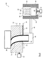
- a detail of an air intake system of an internal combustion engine of a motor vehicle with a duct part which is connected to a fitting, whereby the duct part is shown in a longitudinal section;
- Figure 2
- an apparatus for connecting the duct part of the pipe system of
figure 1 with the fitting in an early production step; - Figure 3
- the apparatus of
figure 2 in a posterior production step. - In the drawings, equal or similar elements are referred to by equal reference numerals. The drawings are merely schematic representations, not intended to portray specific parameters of the invention. Moreover, the drawings are intended to depict only typical embodiments of the invention and therefore should not be considered as limiting the scope of the invention.
- In
figure 1 a detail of anair intake system 10 of an internal combustion engine of a motor vehicle is depicted. Theair intake system 10 has afirst duct part 12. Thefirst duct part 12 is shown in a longitudinal section. Thefirst duct part 12 is blow-molded of polyamide. The polyamide is chemically strengthened with 15% glass fiber. Favorably so-called "PA6 15% GF" or "PA666 15% GF" can be used. An internal diameter of thefirst duct part 12 at its shownconnection end 16 varies between 15 mm and 70 mm, favorably between 47 mm and 52 mm. The internal diameter is indicated infigure 1 with adouble arrow 14. A wall thickness of thefirst duct part 12 is between 2 mm and 4 mm, favorably 3 mm. - The
air intake system 10 further has a fitting 18 for connecting thefirst duct part 12 with asecond duct part 20 of theair intake system 10. The fitting 18 is a tube section. Infigure 1 it is shown in a side view. The fitting 18 is inserted tightly in the connection end 16 of thefirst duct part 12. Thefirst duct part 12 is shrinked on the fitting 18. Thefirst duct part 12 is connected to the fitting 18 by a combination of material engagement, nonpositive connection and positive locking connection. - The fitting 18 is made of plastic. It is connected in one piece to the
second duct part 20. Thefirst duct part 12 and the fitting 18 are made of different materials. The radial outer circumferential side of the fitting 18 is sawtoothed in axial direction. An imaginary axis of the fitting 18 is indicated with abroken line 22. The shape of the pipe wall of thefirst duct part 12 is adapted to the radial outer circumferential side of the fitting 18. In this way the positive locking connection between thefirst duct part 12 and the fitting 18 is realized. An external diameter of the fitting 18 corresponds to theinternal diameter 14 of the connection end 16 of thefirst duct part 12. It is between 35 mm and 70 mm. Favorably it is between 47 mm and 52 mm. A wall thickness of the fitting 18 is between 2 mm and 4 mm, favorably 3 mm. Due to the tight shrinking of thefirst duct part 12, the nonpositive connection by actuation by adherence is realized. - In
figures 2 and3 anapparatus 24 for connecting thefirst duct part 12 with thesecond duct part 20 by use of the fitting 18 is shown in two different production steps. - The
apparatus 24 has anextruder 26 for extruding polyamide to a parison which is formed in a blowingmold 28 to thefirst duct part 12. Further theapparatus 24 has asuction housing 30, into which a leading end of the parison is sucked for forming the parison to thefirst duct part 12. Thesuction housing 30 is placed on the opposite side of theextruder 26. It has anopening 31. In a state of extruding and blow molding of thefirst duct part 12, theopening 31 is connected with anoutlet opening 32 of the blowingmold 28. The state of theapparatus 24 of extruding and blow molding of thefirst duct part 12 is shown infigure 2 . Theextruder 26 and thesuction housing 30 are fixed relative to another. - Between the blowing
mold 28 and the suction housing 30 ablade 36 for trimming thefirst duct part 12 is mounted on thesuction housing 30. Theblade 36 is movable parallel to a surface of the blowingmold 28, which abuts on thesuction housing 30. Infigure 2 a moving direction of theblade 36 is indicated with anarrow 38. - The blowing
mold 28 is movable in direction of anarrow 34 relative to theextruder 26 and thesuction housing 30 toward a device for inserting 40 the fitting 18 tight in connection end 16 of thefirst duct part 12. Therefore theapparatus 24 has adriver 42 for moving the blowingmold 28 toward the device for inserting 14. Ahousing 44 of the device for inserting 40 is affixed to thesuction housing 30 by abridge 46. At a further favorable contrary embodiment, the blowingmould 28 is fixed and the fitting apparatus is moved. - The
housing 44 has acylindrical interior 48, in which thesecond duct part 20 with the fitting 18 can be placed. At a front side of the interior 48 thehousing 44 has an assemblingopening 50. In the state of inserting the fitting 18, the assemblingopening 50 is coaxial to the outlet opening 32 of the blowingmold 28. The state of inserting the fitting 18 of theapparatus 24 is shown infigure 3 . - On the side opposite to the assembling
opening 50, thehousing 44 has anactuator opening 52. Theactuator opening 52 is coaxial to the assemblingopening 50. Apiston 54 of anactuator 56 leads through theactuator opening 52. Thepiston 54 is movable in the interior 48. A moving direction of thepiston 54 is axial to the interior 48. Infigure 3 , the moving direction is indicated with anarrow 58. - Near the assembling
opening 50, acylindrical heating element 60 is placed at the radial inner circumferential side of thehousing 44. Favorably theheating element 60 is electrically operated. - An exemplary method for connecting the
first duct part 12 with thesecond duct part 20 by use of the fitting 18 is described with the help offigures 2 and3 . - The
apparatus 24 is in its state of extruding as shown infigure 2 . Theextruder 26 is provided with the polyamide for thefirst duct part 12. The pre-castedsecond duct part 20 with the fitting 18 is placed in theinterior 48 of thehousing 44 of the device for inserting 40. The fitting 18 is coaxial to the assemblingopening 50. The free end of the fitting 18 points to the assemblingopening 50. Thesecond duct part 20 is mounted on the free end of thepiston 54. The fitting 18 is placed inside theheating element 60. - The polyamide is heated and plasticized within the
extruder 26. The plasticized polyamide is extruded with theextruder 26 and blown to the parison in the blowingmold 28. The parison is sucked with its leading end into thesuction housing 30. So the parison is sucked into the blowingmold 28 and formed to thefirst duct part 12. - The
blade 36 is moved indirection 38 to cut off thescrap 62 of the leading end of thefirst duct part 12 which is within thesuction housing 30. So thefirst duct part 12 is trimmed. - The blowing
mold 28 together with thefirst duct part 12 is moved indirection 34 toward the device for inserting 40. As it is shown infigure 3 , the leading end, which realizes the connection end 16 of thefirst duct part 12, then is coaxial to the fitting 18 in theinterior 48 of thehousing 44. - The fitting 18 is heated by the
heating element 60. The radial outer surface of the fitting 18 so is plasticized. - The
piston 54 is moved by theactuator 56 in movingdirection 58 toward the assemblingopening 50, so that the fitting 18 is pushed in the still plasticized connection end 16 of thefirst duct part 12. - The plasticized
first duct part 12 is cooled down. For this the blowingmold 28 can be cooled down. Thereby the plasticizedfirst duct part 12 is shrinked on the fitting 18. During the shrinkage of thefirst duct part 12 the shape of its pipe wall adapts to the profile of the radial outer circumferential side of the fitting 18. The plasticized material on the radial outer circumferential side of the fitting 18 fuses with the plasticized material of thefirst duct part 12 for realizing the material engagement. Thefirst duct part 12 and thesecond duct part 20 are connected tight by use of the fitting 18. - After the connection of the
first duct part 12 with the fitting 18 is firm, the blowingmold 28 is removed from thehousing 44. The blowingmold 28 is opened and thefirst duct part 12 with the fitting 18 and thesecond duct part 20 are removed. - The invention is not limited to an
air intake system 10 of an internal combustion engine of a motor vehicle. The invention can also be applied for other kinds of pipe systems for fluids. For example it can be used for a turbocharger of an internal combustion engine. The invention can be applied for pipe systems for other gases or liquids, for example oil, fuel or water. The invention is further applicable to other kinds of internal combustion engines, for example to industrial engines. - The
air intake system 10 can have more than one blow-moldedfirst duct part 12. Theair intake system 10 can have more than onefitting 18. - Instead of being connected with the
second duct part 20, thefirst duct part 12 can also be connected with another part of theair intake system 10, for example with a housing of an air filter or a so-called Christmas tree. - The
internal diameter 14 of the connection end 16 of thefirst duct part 12 can be less than 35 mm or more than 70 mm. Accordingly, the external diameter of the fitting 18 can be less than 35 mm or more than 70 mm. - The wall thickness of the
first duct part 12 can be less than 2 mm or more than 4 mm. The wall thickness of the fitting 18 can be less than 2 mm or more than 4 mm. - Instead of being sawtoothed the radial outer circumferential side of the fitting 18 can be graded in axial direction in a different way. For example it can be wavy. The radial outer circumferential side of the fitting 18 can also be straight in axial direction.
- The connection between the
first duct part 12 and the fitting 18 can be realized by material engagement or nonpositive connection, in particular actuation by adherence, or positive locking connection or a combination of those connection types. - The
first duct part 12 also can be made of polyamide which is strengthened with more or less than 15% glass fiber. Also polyamide without glass fiber can be used. Thefirst duct part 12 can also be made of another kind of plastic material. - The fitting 18 can also be made of polyamide. The polyamide also can be chemically strengthened with 15 % glass fiber, for example so-called "PA6 15% GF" or "PA666 15% GF". Also polyamide with more or less than 15 % glass fiber or without glass fiber can be used. The fitting 18 also can be made of a material different from plastic. For example it can be made of metal.
- The
first duct part 12 and the fitting 18 can also be made of the same material. - A gasket can be placed between the
first duct part 12 and the fitting 18. - Instead of one
cylindrical heating element 60 also multiple heating elements can be placed at the radial inner circumferential side of thehousing 44. - The order of the procedural steps of the exemplary method for connecting the
first duct part 12 with the fitting 18 can be different. - Also an alternative method for connecting the
duct parts - The
first duct part 12 can be shrinked on the fitting 18 without heating the fitting 18 before. - The
first duct part 12 can be connected with the fitting 18 by use of an apparatus different from the exemplary describedapparatus 24.
Claims (10)
- Pipe system for a fluid, in particular a gas, in particular of an intake system (10) or a turbocharger of an internal combustion engine, in particular of a motor vehicle, having at least one blow-molded duct part (12) made of plastic and at least one fitting (18) for connecting the at least one blow-molded duct part (12) with another part (20) of the pipe system (10), whereby the fitting (18) is inserted tight in the at least one blow-molded duct part (12), characterized in that, the at least one blow-molded duct part (12) is shrinked on the at least one fitting (18).
- Pipe system according to claim 1, characterized in that, the at least one blow-molded duct part (12) is connected to the at least one fitting (18) by material engagement.
- Pipe system according to claim 1 or 2, characterized in that, the at least one fitting (18) is made of plastic.
- Pipe system according to one of the previous claims, characterized in that, the at least one blow-molded duct part (12) is made of polyamide.
- Pipe system according to one of the previous claims, characterized in that, the at least one blow-molded duct part (12) and the at least one fitting (18) are made of different materials.
- Pipe system according to one of the previous claims, characterized in that, a gasket is placed between the at least one blow-molded duct part and the at least one fitting.
- Method for connecting at least one duct part (12) of a pipe system for a fluid, in particular a gas, in particular of an intake system (10) or a turbocharger of an internal combustion engine, in particular of a motor vehicle, with another part (20) of the pipe system (10) by use of at least one fitting (18), whereby the at least one duct part (12) is made of plastic by a blow molding process and the at least one fitting (18) is inserted tight in the at least one blow-molded duct part (12), characterized in that, the plastic material for realizing the at least one blow-molded duct part (12) is plasticized by heating and formed in a blowing mold (28), the plasticized at least one blow-molded duct part (12) is shrinked on the at least one fitting (18), the plasticized at least one blow-molded duct part (12) is cooled down.
- Method according to claim 7, characterized in that, the at least one fitting (18) is heated before the plasticized at least one duct part (12) is shrinked on the at least one fitting (18).
- Method according to claim 6 or 7, characterized in that, the at least one fitting (18) is made of plastic.
- Apparatus (24) for connecting at least one duct part (12) of a pipe system for a fluid, in particular of an intake system (10) or a turbocharger of an internal combustion engine, in particular of a motor vehicle, with another part (20) of the pipe system (10) by use of at least one fitting (18), having an extruder (26) for extruding a plastic material in a blowing mold (28) for blow molding the at least one duct part (12) and having a device for inserting (40) the at least one fitting (18) tight in the at least one blow-molded duct part (12), characterized by a cutting device (36) for trimming the at least one blow-molded duct part (12), a driver (42) for moving the blowing mold (28) to the device for inserting (40) the at least one fitting (18), whereby the device for inserting (14) the at least one fitting (18) has means (54, 56) for pushing the at least one fitting (18) into the at least one duct part (12).
Priority Applications (3)
| Application Number | Priority Date | Filing Date | Title |
|---|---|---|---|
| EP12290322.2A EP2713038B1 (en) | 2012-09-28 | 2012-09-28 | Pipe system for a fluid, a method and an apparatus for connecting at least one duct part of a pipe system |
| CN201310448245.6A CN103711622B (en) | 2012-09-28 | 2013-09-27 | For the pipe-line system of fluid, the method and apparatus of at least one tube portion for connecting pipe system |
| US14/039,229 US9366205B2 (en) | 2012-09-28 | 2013-09-27 | Pipe system for a fluid, a method and an apparatus for connecting at least one duct part of a pipe system |
Applications Claiming Priority (1)
| Application Number | Priority Date | Filing Date | Title |
|---|---|---|---|
| EP12290322.2A EP2713038B1 (en) | 2012-09-28 | 2012-09-28 | Pipe system for a fluid, a method and an apparatus for connecting at least one duct part of a pipe system |
Publications (2)
| Publication Number | Publication Date |
|---|---|
| EP2713038A1 true EP2713038A1 (en) | 2014-04-02 |
| EP2713038B1 EP2713038B1 (en) | 2018-11-14 |
Family
ID=47115660
Family Applications (1)
| Application Number | Title | Priority Date | Filing Date |
|---|---|---|---|
| EP12290322.2A Active EP2713038B1 (en) | 2012-09-28 | 2012-09-28 | Pipe system for a fluid, a method and an apparatus for connecting at least one duct part of a pipe system |
Country Status (3)
| Country | Link |
|---|---|
| US (1) | US9366205B2 (en) |
| EP (1) | EP2713038B1 (en) |
| CN (1) | CN103711622B (en) |
Cited By (1)
| Publication number | Priority date | Publication date | Assignee | Title |
|---|---|---|---|---|
| EP3334920B1 (en) | 2015-08-12 | 2020-09-09 | ETM Engineering Technologie Marketing GmbH | Air pipe for the intake tract of an internal combustion engine |
Families Citing this family (1)
| Publication number | Priority date | Publication date | Assignee | Title |
|---|---|---|---|---|
| EP3805546A1 (en) | 2019-10-08 | 2021-04-14 | Vitesco Technologies GmbH | Fuel rail assembly for an internal combustion engine and method of manufacturing a fuel rail assembly |
Citations (3)
| Publication number | Priority date | Publication date | Assignee | Title |
|---|---|---|---|---|
| US3929538A (en) * | 1974-06-14 | 1975-12-30 | Clow Corp | Method of assembling a thermoplastic sleeve onto a pipe or the like |
| US4578855A (en) * | 1982-07-21 | 1986-04-01 | Eagle-Picher Industries, Inc. | Article and method for connecting a remote air cleaner to a carburetor or an engine fuel metering device or system |
| WO1998030827A1 (en) * | 1997-01-13 | 1998-07-16 | Snap-Tite, Inc. | Method for shrink-fitting fire hose |
Family Cites Families (5)
| Publication number | Priority date | Publication date | Assignee | Title |
|---|---|---|---|---|
| US5078430A (en) * | 1981-07-10 | 1992-01-07 | Duratron Systems Limited | Pipeline for relining sewers and water lines without excavation |
| US5791696A (en) * | 1993-06-14 | 1998-08-11 | Tokai Rubber Industries, Ltd. | Hose with a protector |
| DE19745192C2 (en) * | 1997-10-13 | 2001-04-19 | Mann & Hummel Filter | Pipe connection and a method for their production |
| US6135158A (en) * | 1998-09-15 | 2000-10-24 | Carlisle Engineered Products | Overmolded air duct with outwardly extending main body lip |
| EP1741968A1 (en) * | 2005-07-08 | 2007-01-10 | Uponor Innovation Ab | Clamping ring |
-
2012
- 2012-09-28 EP EP12290322.2A patent/EP2713038B1/en active Active
-
2013
- 2013-09-27 US US14/039,229 patent/US9366205B2/en active Active
- 2013-09-27 CN CN201310448245.6A patent/CN103711622B/en active Active
Patent Citations (3)
| Publication number | Priority date | Publication date | Assignee | Title |
|---|---|---|---|---|
| US3929538A (en) * | 1974-06-14 | 1975-12-30 | Clow Corp | Method of assembling a thermoplastic sleeve onto a pipe or the like |
| US4578855A (en) * | 1982-07-21 | 1986-04-01 | Eagle-Picher Industries, Inc. | Article and method for connecting a remote air cleaner to a carburetor or an engine fuel metering device or system |
| WO1998030827A1 (en) * | 1997-01-13 | 1998-07-16 | Snap-Tite, Inc. | Method for shrink-fitting fire hose |
Cited By (1)
| Publication number | Priority date | Publication date | Assignee | Title |
|---|---|---|---|---|
| EP3334920B1 (en) | 2015-08-12 | 2020-09-09 | ETM Engineering Technologie Marketing GmbH | Air pipe for the intake tract of an internal combustion engine |
Also Published As
| Publication number | Publication date |
|---|---|
| CN103711622B (en) | 2018-10-26 |
| CN103711622A (en) | 2014-04-09 |
| US9366205B2 (en) | 2016-06-14 |
| US20140090721A1 (en) | 2014-04-03 |
| EP2713038B1 (en) | 2018-11-14 |
Similar Documents
| Publication | Publication Date | Title |
|---|---|---|
| US8372331B2 (en) | Process for manufacturing a plastic fuel tank | |
| CN102066086B (en) | Process for manufacturing a fuel tank | |
| KR101313379B1 (en) | Method for fixing a component to the wall of a fuel tank | |
| EP2387492B1 (en) | Process for manufacturing a fuel tank | |
| CN104118110A (en) | Process for manufacturing a fuel tank equipped with an internal accessory | |
| CN101489759A (en) | Mould for producing hollow bodies from thermoplastic plastic with inserts on their inner faces | |
| CN110271168A (en) | Method and system for component mounting arrangements | |
| WO2014180018A1 (en) | Method for forming two-piece blowed hollow box body with auxiliary male die | |
| CN105082514A (en) | Process for fastening an accessory in a blow molded plastic tank | |
| JP4864897B2 (en) | Method for manufacturing a plastic fuel tank including a built-in neck | |
| EP2713038B1 (en) | Pipe system for a fluid, a method and an apparatus for connecting at least one duct part of a pipe system | |
| CN101080312A (en) | Method for connecting a tubular part made of plastic to a neck of a fuel tank also made of plastic | |
| KR20140106411A (en) | Blow molding process and apparatus | |
| US20100025883A1 (en) | Method for manufacturing a hose | |
| CN106870831A (en) | The pipe of belt lacing | |
| EP2919964B1 (en) | Method for producing a blow moulded fuel filler system for a motor vehicle and fuel filler system for a motor vehicle | |
| EP2677154B1 (en) | Line system for a fluid, method of manufacturing a line system and apparatus for manufacturing a line system | |
| FR2944574A1 (en) | Method for assembling plastic conduit sections of air supply conduit of turbo compressor, involves installing screwed collar clamp around female end of conduit section in order to guarantee sealing at level of junction of sections | |
| EP2884087B1 (en) | Duct system | |
| US20260008223A1 (en) | Method for producing a blow-molded part and a blow-molded part | |
| EP2679797A1 (en) | Duct part of the pipe system for a fluid, method and apparatus for manufacturing a duct part of a pipe system | |
| CN105934326A (en) | Method for producing containers from thermoplastics and plastic containers produced according to the method | |
| JPH04152123A (en) | Blow-molded product having fitting part and its manufacture | |
| EP2832521A1 (en) | Pipe connection arrangement | |
| CN108068295A (en) | Suction and the pipeline clamped and its manufacturing method |
Legal Events
| Date | Code | Title | Description |
|---|---|---|---|
| PUAI | Public reference made under article 153(3) epc to a published international application that has entered the european phase |
Free format text: ORIGINAL CODE: 0009012 |
|
| AK | Designated contracting states |
Kind code of ref document: A1 Designated state(s): AL AT BE BG CH CY CZ DE DK EE ES FI FR GB GR HR HU IE IS IT LI LT LU LV MC MK MT NL NO PL PT RO RS SE SI SK SM TR |
|
| AX | Request for extension of the european patent |
Extension state: BA ME |
|
| 17P | Request for examination filed |
Effective date: 20140929 |
|
| RBV | Designated contracting states (corrected) |
Designated state(s): AL AT BE BG CH CY CZ DE DK EE ES FI FR GB GR HR HU IE IS IT LI LT LU LV MC MK MT NL NO PL PT RO RS SE SI SK SM TR |
|
| 17Q | First examination report despatched |
Effective date: 20160429 |
|
| GRAP | Despatch of communication of intention to grant a patent |
Free format text: ORIGINAL CODE: EPIDOSNIGR1 |
|
| STAA | Information on the status of an ep patent application or granted ep patent |
Free format text: STATUS: GRANT OF PATENT IS INTENDED |
|
| INTG | Intention to grant announced |
Effective date: 20180716 |
|
| GRAS | Grant fee paid |
Free format text: ORIGINAL CODE: EPIDOSNIGR3 |
|
| GRAA | (expected) grant |
Free format text: ORIGINAL CODE: 0009210 |
|
| STAA | Information on the status of an ep patent application or granted ep patent |
Free format text: STATUS: THE PATENT HAS BEEN GRANTED |
|
| RAP1 | Party data changed (applicant data changed or rights of an application transferred) |
Owner name: MANN+HUMMEL GMBH |
|
| RIN1 | Information on inventor provided before grant (corrected) |
Inventor name: GIRARD, DOMINIQUE Inventor name: SARRAZIN, MAXIME |
|
| AK | Designated contracting states |
Kind code of ref document: B1 Designated state(s): AL AT BE BG CH CY CZ DE DK EE ES FI FR GB GR HR HU IE IS IT LI LT LU LV MC MK MT NL NO PL PT RO RS SE SI SK SM TR |
|
| RIN1 | Information on inventor provided before grant (corrected) |
Inventor name: SARRAZIN, MAXIME Inventor name: GIRARD, DOMINIQUE |
|
| REG | Reference to a national code |
Ref country code: CH Ref legal event code: EP Ref country code: AT Ref legal event code: REF Ref document number: 1065124 Country of ref document: AT Kind code of ref document: T Effective date: 20181115 |
|
| REG | Reference to a national code |
Ref country code: DE Ref legal event code: R096 Ref document number: 602012053424 Country of ref document: DE |
|
| REG | Reference to a national code |
Ref country code: IE Ref legal event code: FG4D |
|
| REG | Reference to a national code |
Ref country code: NL Ref legal event code: MP Effective date: 20181114 |
|
| REG | Reference to a national code |
Ref country code: LT Ref legal event code: MG4D |
|
| REG | Reference to a national code |
Ref country code: AT Ref legal event code: MK05 Ref document number: 1065124 Country of ref document: AT Kind code of ref document: T Effective date: 20181114 |
|
| PG25 | Lapsed in a contracting state [announced via postgrant information from national office to epo] |
Ref country code: HR Free format text: LAPSE BECAUSE OF FAILURE TO SUBMIT A TRANSLATION OF THE DESCRIPTION OR TO PAY THE FEE WITHIN THE PRESCRIBED TIME-LIMIT Effective date: 20181114 Ref country code: LT Free format text: LAPSE BECAUSE OF FAILURE TO SUBMIT A TRANSLATION OF THE DESCRIPTION OR TO PAY THE FEE WITHIN THE PRESCRIBED TIME-LIMIT Effective date: 20181114 Ref country code: IS Free format text: LAPSE BECAUSE OF FAILURE TO SUBMIT A TRANSLATION OF THE DESCRIPTION OR TO PAY THE FEE WITHIN THE PRESCRIBED TIME-LIMIT Effective date: 20190314 Ref country code: LV Free format text: LAPSE BECAUSE OF FAILURE TO SUBMIT A TRANSLATION OF THE DESCRIPTION OR TO PAY THE FEE WITHIN THE PRESCRIBED TIME-LIMIT Effective date: 20181114 Ref country code: NO Free format text: LAPSE BECAUSE OF FAILURE TO SUBMIT A TRANSLATION OF THE DESCRIPTION OR TO PAY THE FEE WITHIN THE PRESCRIBED TIME-LIMIT Effective date: 20190214 Ref country code: ES Free format text: LAPSE BECAUSE OF FAILURE TO SUBMIT A TRANSLATION OF THE DESCRIPTION OR TO PAY THE FEE WITHIN THE PRESCRIBED TIME-LIMIT Effective date: 20181114 Ref country code: BG Free format text: LAPSE BECAUSE OF FAILURE TO SUBMIT A TRANSLATION OF THE DESCRIPTION OR TO PAY THE FEE WITHIN THE PRESCRIBED TIME-LIMIT Effective date: 20190214 Ref country code: AT Free format text: LAPSE BECAUSE OF FAILURE TO SUBMIT A TRANSLATION OF THE DESCRIPTION OR TO PAY THE FEE WITHIN THE PRESCRIBED TIME-LIMIT Effective date: 20181114 Ref country code: FI Free format text: LAPSE BECAUSE OF FAILURE TO SUBMIT A TRANSLATION OF THE DESCRIPTION OR TO PAY THE FEE WITHIN THE PRESCRIBED TIME-LIMIT Effective date: 20181114 |
|
| PG25 | Lapsed in a contracting state [announced via postgrant information from national office to epo] |
Ref country code: GR Free format text: LAPSE BECAUSE OF FAILURE TO SUBMIT A TRANSLATION OF THE DESCRIPTION OR TO PAY THE FEE WITHIN THE PRESCRIBED TIME-LIMIT Effective date: 20190215 Ref country code: RS Free format text: LAPSE BECAUSE OF FAILURE TO SUBMIT A TRANSLATION OF THE DESCRIPTION OR TO PAY THE FEE WITHIN THE PRESCRIBED TIME-LIMIT Effective date: 20181114 Ref country code: NL Free format text: LAPSE BECAUSE OF FAILURE TO SUBMIT A TRANSLATION OF THE DESCRIPTION OR TO PAY THE FEE WITHIN THE PRESCRIBED TIME-LIMIT Effective date: 20181114 Ref country code: AL Free format text: LAPSE BECAUSE OF FAILURE TO SUBMIT A TRANSLATION OF THE DESCRIPTION OR TO PAY THE FEE WITHIN THE PRESCRIBED TIME-LIMIT Effective date: 20181114 Ref country code: SE Free format text: LAPSE BECAUSE OF FAILURE TO SUBMIT A TRANSLATION OF THE DESCRIPTION OR TO PAY THE FEE WITHIN THE PRESCRIBED TIME-LIMIT Effective date: 20181114 Ref country code: PT Free format text: LAPSE BECAUSE OF FAILURE TO SUBMIT A TRANSLATION OF THE DESCRIPTION OR TO PAY THE FEE WITHIN THE PRESCRIBED TIME-LIMIT Effective date: 20190314 |
|
| PG25 | Lapsed in a contracting state [announced via postgrant information from national office to epo] |
Ref country code: IT Free format text: LAPSE BECAUSE OF FAILURE TO SUBMIT A TRANSLATION OF THE DESCRIPTION OR TO PAY THE FEE WITHIN THE PRESCRIBED TIME-LIMIT Effective date: 20181114 Ref country code: DK Free format text: LAPSE BECAUSE OF FAILURE TO SUBMIT A TRANSLATION OF THE DESCRIPTION OR TO PAY THE FEE WITHIN THE PRESCRIBED TIME-LIMIT Effective date: 20181114 Ref country code: CZ Free format text: LAPSE BECAUSE OF FAILURE TO SUBMIT A TRANSLATION OF THE DESCRIPTION OR TO PAY THE FEE WITHIN THE PRESCRIBED TIME-LIMIT Effective date: 20181114 Ref country code: PL Free format text: LAPSE BECAUSE OF FAILURE TO SUBMIT A TRANSLATION OF THE DESCRIPTION OR TO PAY THE FEE WITHIN THE PRESCRIBED TIME-LIMIT Effective date: 20181114 |
|
| REG | Reference to a national code |
Ref country code: DE Ref legal event code: R097 Ref document number: 602012053424 Country of ref document: DE |
|
| PG25 | Lapsed in a contracting state [announced via postgrant information from national office to epo] |
Ref country code: SK Free format text: LAPSE BECAUSE OF FAILURE TO SUBMIT A TRANSLATION OF THE DESCRIPTION OR TO PAY THE FEE WITHIN THE PRESCRIBED TIME-LIMIT Effective date: 20181114 Ref country code: RO Free format text: LAPSE BECAUSE OF FAILURE TO SUBMIT A TRANSLATION OF THE DESCRIPTION OR TO PAY THE FEE WITHIN THE PRESCRIBED TIME-LIMIT Effective date: 20181114 Ref country code: EE Free format text: LAPSE BECAUSE OF FAILURE TO SUBMIT A TRANSLATION OF THE DESCRIPTION OR TO PAY THE FEE WITHIN THE PRESCRIBED TIME-LIMIT Effective date: 20181114 Ref country code: SM Free format text: LAPSE BECAUSE OF FAILURE TO SUBMIT A TRANSLATION OF THE DESCRIPTION OR TO PAY THE FEE WITHIN THE PRESCRIBED TIME-LIMIT Effective date: 20181114 |
|
| PLBE | No opposition filed within time limit |
Free format text: ORIGINAL CODE: 0009261 |
|
| STAA | Information on the status of an ep patent application or granted ep patent |
Free format text: STATUS: NO OPPOSITION FILED WITHIN TIME LIMIT |
|
| 26N | No opposition filed |
Effective date: 20190815 |
|
| PG25 | Lapsed in a contracting state [announced via postgrant information from national office to epo] |
Ref country code: SI Free format text: LAPSE BECAUSE OF FAILURE TO SUBMIT A TRANSLATION OF THE DESCRIPTION OR TO PAY THE FEE WITHIN THE PRESCRIBED TIME-LIMIT Effective date: 20181114 |
|
| PG25 | Lapsed in a contracting state [announced via postgrant information from national office to epo] |
Ref country code: TR Free format text: LAPSE BECAUSE OF FAILURE TO SUBMIT A TRANSLATION OF THE DESCRIPTION OR TO PAY THE FEE WITHIN THE PRESCRIBED TIME-LIMIT Effective date: 20181114 |
|
| PG25 | Lapsed in a contracting state [announced via postgrant information from national office to epo] |
Ref country code: MC Free format text: LAPSE BECAUSE OF FAILURE TO SUBMIT A TRANSLATION OF THE DESCRIPTION OR TO PAY THE FEE WITHIN THE PRESCRIBED TIME-LIMIT Effective date: 20181114 |
|
| REG | Reference to a national code |
Ref country code: CH Ref legal event code: PL |
|
| PG25 | Lapsed in a contracting state [announced via postgrant information from national office to epo] |
Ref country code: LI Free format text: LAPSE BECAUSE OF NON-PAYMENT OF DUE FEES Effective date: 20190930 Ref country code: CH Free format text: LAPSE BECAUSE OF NON-PAYMENT OF DUE FEES Effective date: 20190930 Ref country code: LU Free format text: LAPSE BECAUSE OF NON-PAYMENT OF DUE FEES Effective date: 20190928 Ref country code: IE Free format text: LAPSE BECAUSE OF NON-PAYMENT OF DUE FEES Effective date: 20190928 |
|
| REG | Reference to a national code |
Ref country code: BE Ref legal event code: MM Effective date: 20190930 |
|
| PG25 | Lapsed in a contracting state [announced via postgrant information from national office to epo] |
Ref country code: BE Free format text: LAPSE BECAUSE OF NON-PAYMENT OF DUE FEES Effective date: 20190930 |
|
| GBPC | Gb: european patent ceased through non-payment of renewal fee |
Effective date: 20190928 |
|
| PG25 | Lapsed in a contracting state [announced via postgrant information from national office to epo] |
Ref country code: GB Free format text: LAPSE BECAUSE OF NON-PAYMENT OF DUE FEES Effective date: 20190928 |
|
| PG25 | Lapsed in a contracting state [announced via postgrant information from national office to epo] |
Ref country code: CY Free format text: LAPSE BECAUSE OF FAILURE TO SUBMIT A TRANSLATION OF THE DESCRIPTION OR TO PAY THE FEE WITHIN THE PRESCRIBED TIME-LIMIT Effective date: 20181114 |
|
| PG25 | Lapsed in a contracting state [announced via postgrant information from national office to epo] |
Ref country code: HU Free format text: LAPSE BECAUSE OF FAILURE TO SUBMIT A TRANSLATION OF THE DESCRIPTION OR TO PAY THE FEE WITHIN THE PRESCRIBED TIME-LIMIT; INVALID AB INITIO Effective date: 20120928 Ref country code: MT Free format text: LAPSE BECAUSE OF FAILURE TO SUBMIT A TRANSLATION OF THE DESCRIPTION OR TO PAY THE FEE WITHIN THE PRESCRIBED TIME-LIMIT Effective date: 20181114 |
|
| PG25 | Lapsed in a contracting state [announced via postgrant information from national office to epo] |
Ref country code: MK Free format text: LAPSE BECAUSE OF FAILURE TO SUBMIT A TRANSLATION OF THE DESCRIPTION OR TO PAY THE FEE WITHIN THE PRESCRIBED TIME-LIMIT Effective date: 20181114 |
|
| PGFP | Annual fee paid to national office [announced via postgrant information from national office to epo] |
Ref country code: DE Payment date: 20250919 Year of fee payment: 14 |
|
| PGFP | Annual fee paid to national office [announced via postgrant information from national office to epo] |
Ref country code: FR Payment date: 20250922 Year of fee payment: 14 |