EP2713028A2 - Adaptive fuel manifold filling function for improved engine start - Google Patents
Adaptive fuel manifold filling function for improved engine start Download PDFInfo
- Publication number
- EP2713028A2 EP2713028A2 EP20130173972 EP13173972A EP2713028A2 EP 2713028 A2 EP2713028 A2 EP 2713028A2 EP 20130173972 EP20130173972 EP 20130173972 EP 13173972 A EP13173972 A EP 13173972A EP 2713028 A2 EP2713028 A2 EP 2713028A2
- Authority
- EP
- European Patent Office
- Prior art keywords
- flow rate
- fuel
- acceleration threshold
- engine
- acceleration
- Prior art date
- Legal status (The legal status is an assumption and is not a legal conclusion. Google has not performed a legal analysis and makes no representation as to the accuracy of the status listed.)
- Granted
Links
Images


Classifications
-
- F—MECHANICAL ENGINEERING; LIGHTING; HEATING; WEAPONS; BLASTING
- F02—COMBUSTION ENGINES; HOT-GAS OR COMBUSTION-PRODUCT ENGINE PLANTS
- F02C—GAS-TURBINE PLANTS; AIR INTAKES FOR JET-PROPULSION PLANTS; CONTROLLING FUEL SUPPLY IN AIR-BREATHING JET-PROPULSION PLANTS
- F02C7/00—Features, components parts, details or accessories, not provided for in, or of interest apart form groups F02C1/00 - F02C6/00; Air intakes for jet-propulsion plants
- F02C7/26—Starting; Ignition
-
- F—MECHANICAL ENGINEERING; LIGHTING; HEATING; WEAPONS; BLASTING
- F02—COMBUSTION ENGINES; HOT-GAS OR COMBUSTION-PRODUCT ENGINE PLANTS
- F02C—GAS-TURBINE PLANTS; AIR INTAKES FOR JET-PROPULSION PLANTS; CONTROLLING FUEL SUPPLY IN AIR-BREATHING JET-PROPULSION PLANTS
- F02C9/00—Controlling gas-turbine plants; Controlling fuel supply in air- breathing jet-propulsion plants
- F02C9/16—Control of working fluid flow
- F02C9/20—Control of working fluid flow by throttling; by adjusting vanes
-
- F—MECHANICAL ENGINEERING; LIGHTING; HEATING; WEAPONS; BLASTING
- F02—COMBUSTION ENGINES; HOT-GAS OR COMBUSTION-PRODUCT ENGINE PLANTS
- F02C—GAS-TURBINE PLANTS; AIR INTAKES FOR JET-PROPULSION PLANTS; CONTROLLING FUEL SUPPLY IN AIR-BREATHING JET-PROPULSION PLANTS
- F02C9/00—Controlling gas-turbine plants; Controlling fuel supply in air- breathing jet-propulsion plants
- F02C9/26—Control of fuel supply
- F02C9/28—Regulating systems responsive to plant or ambient parameters, e.g. temperature, pressure, rotor speed
Definitions
- the application relates generally to a system and method for filling an engine fuel manifold.
- a start sequence may be used to coordinate engine speed, ignition, and fuel delivery mechanism to achieve a reliable start.
- successful engine start may be obtained within a given range of fuel/air (FAR) ratio capable of sustaining combustion in the engine.
- FAR fuel/air
- an appropriate amount of fuel should be sent to the engine combustor at an appropriate speed, i.e. engine speed and fuel delivery should be coordinated, in order to create the proper FAR condition.
- Manifold priming however delays the flow of fuel out of the engine's fuel manifold.
- the fuel may be sent to the engine's combustor too late. This may result in an excessively poor fuel/air mixture, which may be too lean to produce engine light-up.
- the fuel manifold is likely to be primed more quickly. The fuel may be sent to the engine combustor too quickly, resulting in an excessively rich mixture. In this case, although light-up is likely to be produced, extreme temperature and flames may result, leading to accelerated engine deterioration.
- a system for filling a fuel manifold of an engine comprising a memory, a receiving unit adapted to receive a present measurement of a speed of the engine, and a processing unit coupled to the memory, the processing unit adapted to compute from the received measurement a flow rate of fuel to be supplied to the fuel manifold for filling thereof and to generate an output signal for causing delivery of the fuel to the fuel manifold according to the computed flow rate.
- a method for filling a fuel manifold of an engine comprising receiving a present measurement of a speed of the engine, computing from the received measurement a flow rate of fuel to be supplied to the fuel manifold for filling thereof, and generating an output signal for causing delivery of the fuel to the fuel manifold according to the computed flow rate.
- a system for filling a fuel manifold of an engine comprising means for receiving a present measurement of a speed of the engine, means for computing from the received measurement a flow rate of fuel to be supplied to the fuel manifold for filling thereof, and means for generating an output signal for causing delivery of the fuel to the fuel manifold according to the computed flow rate.
- Fig.1 illustrates a gas turbine engine 10 of a type preferably provided for use in subsonic flight, generally comprising in serial flow communication, a compressor section 12 for pressurizing the air, a combustor 14 in which the compressed air is mixed with fuel provided by a manifold 16 and ignited for generating an annular stream of hot combustion gases, and a turbine section 18 for extracting energy from the combustion gases.
- the turbine section 18 includes a compressor turbine 20 in driving engagement with the compressor section 12 through a high pressure shaft 22, and a power turbine 24 in driving engagement with a power shaft 26.
- the power shaft 26 is in driving engagement with an output shaft 28 through a reduction gearbox (not shown).
- the system 100 illustratively comprises a control unit 102 controlling the flow of fuel into the fuel manifold 16.
- the control unit 102 may comprise a digital computer or Engine Control Unit (ECU) (not shown) using a Central Processing Unit (CPU) (not shown).
- the control unit 102 may further be coupled to storage or memory 104.
- the memory 104 may be a main memory, such as a high speed Random Access Memory (RAM), or an auxiliary storage unit, such as a hard disk, an erasable programmable read only memory (EPROM), or flash memory (e.g. memory sticks and secure digital (SD) cards).
- RAM Random Access Memory
- EPROM erasable programmable read only memory
- SD secure digital
- the memory 104 may further be any other type of memory, for example an optical storage media such as a videodisc and a compact disc.
- One or more databases may be integrated directly into the memory 104 or may be provided separately therefrom.
- the databases may be provided as collections of data or information organized for rapid search and retrieval by a computer.
- the databases may be structured to facilitate storage, retrieval, modification, and deletion of data in conjunction with various data-processing operations.
- the databases may consist of a file or sets of files that can be broken down into records, each of which consists of one or more fields. Database information may be retrieved through queries using keywords and sorting commands, in order to rapidly search, rearrange, group, and select the field.
- the databases may be any organization of data on a data storage medium, such as one or more servers.
- the control unit 102 may be in communication with the hardware of the engine 10 and receive from at least one speed sensor 106 coupled to the engine 10 measurements of the engine's gas generator speed (Ng).
- the control unit 102 may also be coupled to a temperature sensor 107 for detecting a light-up condition of the engine 10, as will be discussed further below.
- the control unit 102 may be used to control the amount of fuel delivered to the fuel manifold 16 via fuel inlet pipes (not shown).
- the control unit 102 illustratively uses an adaptive filling function to determine, in accordance with the currently received speed measurement, a suitable rate of fuel flow into the fuel manifold 16.
- the control unit 102 illustratively computes a boosted fuel flow rate that is to be used to fill the fuel manifold 16 for a predetermined duration and/or until engine ignition or light-up is achieved.
- the filling of the fuel manifold 16 may thus be precisely controlled so as to match the engine's gas generator speed, thereby improving the starting capability of the engine 10.
- the appropriate fuel/air ratio condition can be obtained for successful engine start by sending an appropriate amount of fuel to the engine combustor 14 at the correct compressor rotational speed.
- the fuel manifold 16 is illustratively filled using a predetermined open loop schedule in addition to the boosted fuel flow rate determined by implementing the adaptive filling function logic.
- control unit 102 illustratively comprises a receiving module 108, an acceleration computation module 109, a comparison module 110, and a flow rate computation module 112.
- the receiving module 108 may receive an input signal comprising an activation signal indicating that it is desired to enable the filling function.
- the activation signal may be received from the aircraft command system, i.e. from the pilot.
- Such an activation signal is illustratively the start signal of the engine 10, such that the filling function may be activated at every start of the engine 10.
- the receiving module 108 illustratively receives from the speed sensor 106 a measurement of the engine's gas generator speed (Ng).
- the receiving module 108 may further retrieve from the memory 104 a value of the predetermined duration for which the filling function should be active.
- the receiving module 108 may then calculate the time that has elapsed between the moment the activation signal has been received and the present time. If the elapsed time is greater than the retrieved activation duration, the receiving module 108 determines that the activation duration has lapsed and that the filling function should no longer be implemented by the control unit 102. The receiving module 108 may then send a duration lapse signal to the flow rate computation module 112. The latter then retrieves a predetermined open-loop schedule from the memory 104 and generate an output signal indicating that fuel is to be supplied to the fuel manifold 16 according to an open-loop fuel flow rate.
- the receiving module 108 determines that the activation duration has not lapsed, the receiving module 108 transmits the speed measurement to the acceleration computation module 109.
- the acceleration computation module 109 may then compute from the received measurement the change rate of the engine's speed, i.e. the engine's acceleration (N2dot).
- the acceleration computation module 109 computes the engine acceleration by taking the derivative of the speed and sends the computed acceleration to the comparison module 110.
- the comparison module 110 compares the received acceleration to a predetermined minimum acceleration threshold and a predetermined maximum acceleration threshold.
- the thresholds are illustratively stored in the memory 104 and may be retrieved by the comparison module 110 for this purpose. Comparison of the computed acceleration to the threshold enables computation of a multiplier (BWf), which may be used to derive the boosted value of the fuel flow rate (Filling_Wf). Indeed, the comparison module 110 determines whether the engine's acceleration is below the minimum threshold, above the maximum threshold, or between the minimum and the maximum threshold. The comparison result is then sent to the flow rate computation module 112, which determines therefrom the multiplier BWf and accordingly the boosted value of the fuel flow rate.
- BWf multiplier
- these measurements may be received periodically from the speed sensor 106 and stored over time in the memory 104 along with the corresponding values of the engine acceleration computed by the acceleration computation module 109.
- the value of Max_N2dot may therefore be obtained by searching in the memory 104 for the maximum one of the stored acceleration values.
- the variables [max_threshold] and [min_threshold] respectively correspond to the predetermined maximum and minimum acceleration thresholds stored in the memory 104 and retrieved therefrom by the comparison module 110.
- the variables [max_threshold] and [min_threshold] may vary as a function of altitude and outside air temperature. For example, at sea-level altitude and a temperature of -10 degrees Celsius, the maximum acceleration threshold may have a value of 4.2%Ng/sec while the minimum acceleration threshold may have a value of 3%Ng/sec. When an altitude of 20kft (6096m) is reached, the value of the maximum acceleration threshold may then become 5.8%Ng/sec while the value of the minimum acceleration threshold may become 3.4%Ng/sec.
- the value [max_boost_Wf_value] may be predetermined and stored in the memory 104 for subsequent retrieval by the comparison module 110 to compute the boosted fuel flow rate Filling_Wf.
- [max_boost_Wf_value] is set to 60PPH. It should however be understood that other values may apply.
- the flow rate computation module 112 generates an output signal accordingly, the output signal indicative of the boosted fuel flow rate that is to be sent via the fuel inlet pipes to the fuel manifold 16 for filling the latter. Since this boosted fuel flow rate is computed on the basis of the engine's speed received at the control unit 102, the fuel manifold 16 may be filled on time to match the speed of the engine 10 using the adaptive filling function described above. As a result, appropriate fuel/air ratio conditions can be created and successful engine light-up achieved.
- Fig. 4 illustrates a plot 200 of the fuel flow rate computed upon the control unit 102 implementing the adaptive filling function logic, a plot 202 of the acceleration of the engine 10, and a plot 204 of the overall fuel flow rate supplied to the engine 10 subsequent to implementation of the adaptive filling function logic, all as a function of the speed of the engine 10.
- the control unit 102 may implement the adaptive filling function by default. As is apparent from equations (1) to (3) and as can be seen from plot 200, the adaptive filling function may be used to adjust the fuel flow rate as soon as the engine's acceleration (N2dot) is greater than the minimum acceleration threshold [min_threshold], i.e. the multiplier BWf is non-zero.
- the adaptive filling function may be enabled for any type of engine start-up.
- the control unit 102 may implement the adaptive filling function logic prior to or during flight. As discussed above, the adaptive filling function may further be enabled over a fixed duration, e.g. 1.20 seconds, in addition to carrying out the open-loop fuel schedule.
- Such a schedule may be used to specify a predetermined amount of fuel to be delivered to the fuel manifold 16 for a particular operating condition of the engine 10.
- the open loop schedule can be used to provide precise fuel injection timing and regulation using a fixed calculation or function developed by careful measurement and data taken from a representative engine 10.
- the open-loop schedule may be stored in the memory 104 and retrieved therefrom by the flow rate computation module 112 of the control unit 102 in order to determine the fuel flow rate to be delivered to the fuel manifold 16 according to the schedule.
- control unit 102 may further disable the adaptive filling function upon the detection of engine light-up. Such detection may, for example, be accomplished by the control unit 102 checking an output signal generated by the temperature sensor (reference 107 in Figure 2 ) capable of detecting exhaust gas temperature.
- the signal output by the temperature sensor 107 illustratively comprises an exhaust gas temperature measurement and may be received at the receiving module 108 of the control unit 102.
- the receiving module 108 may then determine from the received signal, i.e. the temperature measurement, whether engine light-up has occurred. For example, this may be effected by comparing the received temperature measurement to a temperature threshold retrieved from the memory 104.
- light-up detection may be effected in a variety of other ways known to those skilled in the art.
- a light-up detection signal may be transmitted to the flow rate computation module 112, which will determine the appropriate fuel flow rate to be delivered to the fuel manifold 16.
- the control unit 102 has illustratively already automatically returned to the open-loop schedule at the time the light-up is detected.
- a duration lapse signal has illustratively already been received at the flow rate computation module 112 prior to receiving the light-up detection signal.
- the flow rate computation module 112 upon receiving the duration lapse signal, the flow rate computation module 112 will illustratively have retrieved the open-loop schedule from the memory 104 and generated an output signal indicating that the fuel flow rate sent to the fuel manifold 16 is to follow the retrieved open-loop schedule.
- the flow rate computation module 112 may then determine that the current fuel flow rate already follows the previously retrieved open-loop schedule and no additional action needs to be taken to adjust the fuel flow rate. Otherwise, if light-up is detected before the lapse of the fixed duration, the filling function is disabled and the control unit 102 returns to the open-loop schedule at that time (see plot 204). For this purpose, upon receiving the light-up detection signal, the flow rate computation module 112 illustratively retrieves the open-loop schedule from the memory 104 and outputs a signal indicating that the fuel flow rate is to follow the retrieved open-loop schedule.
- the flow rate computation module 112 illustratively computes a gradual step down in fuel flow to achieve a smooth transition.
- This gradual step down may be performed over a range of 3% of the gas generator speed (Ng).
- Ng gas generator speed
- the filling function is illustratively disabled and the fuel flow rate is gradually lowered towards the open-loop fuel flow rate over the range of speeds from 10,000 rpm to 10,000 rpm + 3% of 10,000 rpm, i.e. 10,300 rpm. It should be understood that ranges other then 3% Ng may also be used.
- plot 204 which shows that, upon the adaptive filling function being enabled, the boosted fuel flow rate computed by the flow rate computation module 112 is added to the predetermined open loop fuel schedule over the fixed duration.
- fuel is illustratively delivered to the fuel manifold 16 according to a flow rate equal to the sum of the boosted fuel flow rate (Wf) computed using equation (4) and a fuel flow rate determined by the open-loop schedule.
- Wf boosted fuel flow rate
- the fuel manifold 16 may be filled according to the open-loop fuel flow rate only.
- the fuel flow rate supplied to the fuel manifold 16 may further vary according to the starter torque.
- the compressor rotational speed is illustratively obtained through the use of a motive power source, such as an electrical or pneumatic starter (not shown) drivably coupled to the engine 10 and operated to produce rotation thereof.
- a motive power source such as an electrical or pneumatic starter (not shown) drivably coupled to the engine 10 and operated to produce rotation thereof.
- a fuel delivery pump and an igniter (not shown) may be actuated to effect ignition in the combustor 14.
- the starter may be disengaged.
- the starter torque may however vary, producing different engine core accelerations as shown in plot 202.
- the adaptive filling function implemented by the control unit 102 may not only adapt to starter torque variations but to other parameters as well. Indeed, various conditions may produce changes in the rotor acceleration. Such conditions include, but are not limited to, starter torque variations, A/C forward speed in case of in-flight re-start of the engine 10, ambient air temperature, engine oil temperature, and aircraft battery depletion. For example, an increase in ambient air temperature or engine oil temperature can result in an increase in rotor acceleration. Also, a low battery may result in low starter torque, leading to low acceleration. By taking into account to the rotor acceleration, the adaptive filling function implemented by the control unit 102 can therefore adapt to these different conditions.
- the method 300 comprises receiving at step 302 an activation signal.
- the predetermined duration for which it is desired to activate the filling function may further be retrieved at step 304.
- a measurement of a speed of the engine 10 from the speed sensor 106 may then be received at step 306.
- the method 300 may determine at step 308 whether the activation duration has lapsed. If this is the case, the open-loop schedule may be applied at step 310. Otherwise, the method 300 may determine at step 312 whether light-up of the engine 10 has been detected. If this is the case, the method 300 may flow to the step 310 of applying the open-loop schedule.
- the acceleration of the engine 10 may be computed at step 314 from the received speed measurement.
- the boosted fuel flow rate may further be computed at step 316 and added to the open-loop schedule at step 318 for filling the fuel manifold 16 accordingly, as discussed above.
- the method 300 may then flow back to the step 306 of receiving a speed measurement and the process may be repeated.
- the step 316 of computing the boost fuel flow rate illustratively comprises retrieving at step 320 a maximum recorded engine acceleration (Max_N2dot) and minimum and maximum acceleration thresholds (min_threshold and max_threshold).
- the step 316 further comprises comparing at step 322 the acceleration computed at step 314 to the thresholds retrieved at step 320.
- the multiplier (BWf) may then be computed at step 324 on the basis of the comparison result.
- step 324 illustratively comprises determining the multiplier according to equations (1), (2), and (3) discussed above.
- the step 316 may further comprise retrieving a maximum boosted fuel flow rate (max_boost_Wf_value) at step 326 and multiplying at step 328 the retrieved maximum boosted fuel flow rate by the multiplier computed at step 324.
- the multiplication performed at step 328 is illustratively effected according to equation (4) discussed above.
- the step 324 of computing the multiplier illustratively comprises determining at step 330 whether the acceleration computed at step 314 is lower than the minimum acceleration threshold. If this is the case, the method 300 flows to the step 332 of setting the multiplier to zero. Otherwise, the method 300 flows to the step 334 of determining whether the acceleration computed at step 314 is greater than the maximum acceleration threshold. If this is the case, the multiplier is set to one at step 336.
- the method computes at step 338 the difference between the maximum recorded engine acceleration and the minimum acceleration threshold, computes the difference between the maximum acceleration threshold and the minimum acceleration threshold at step 340, and computes at step 342 a ratio of the differences to determine a value of the multiplier.
Landscapes
- Engineering & Computer Science (AREA)
- Chemical & Material Sciences (AREA)
- Combustion & Propulsion (AREA)
- Mechanical Engineering (AREA)
- General Engineering & Computer Science (AREA)
- Physics & Mathematics (AREA)
- Fluid Mechanics (AREA)
- Combined Controls Of Internal Combustion Engines (AREA)
- Electrical Control Of Air Or Fuel Supplied To Internal-Combustion Engine (AREA)
Abstract
Description
- The application relates generally to a system and method for filling an engine fuel manifold.
- In typical gas turbine engine start systems, a start sequence may be used to coordinate engine speed, ignition, and fuel delivery mechanism to achieve a reliable start. In particular, successful engine start may be obtained within a given range of fuel/air (FAR) ratio capable of sustaining combustion in the engine. As air flow within the engine is a consequence of compressor rotational speed, an appropriate amount of fuel should be sent to the engine combustor at an appropriate speed, i.e. engine speed and fuel delivery should be coordinated, in order to create the proper FAR condition.
- Manifold priming however delays the flow of fuel out of the engine's fuel manifold. On the one hand, if the engine has high acceleration and the manifold is not quickly primed, the fuel may be sent to the engine's combustor too late. This may result in an excessively poor fuel/air mixture, which may be too lean to produce engine light-up. On the other hand, if the engine has low acceleration, the fuel manifold is likely to be primed more quickly. The fuel may be sent to the engine combustor too quickly, resulting in an excessively rich mixture. In this case, although light-up is likely to be produced, extreme temperature and flames may result, leading to accelerated engine deterioration.
- There is therefore a need for an improved system and method for filling an engine fuel manifold.
- In one aspect, there is provided a system for filling a fuel manifold of an engine, the system comprising a memory, a receiving unit adapted to receive a present measurement of a speed of the engine, and a processing unit coupled to the memory, the processing unit adapted to compute from the received measurement a flow rate of fuel to be supplied to the fuel manifold for filling thereof and to generate an output signal for causing delivery of the fuel to the fuel manifold according to the computed flow rate.
- In another aspect, there is provided a method for filling a fuel manifold of an engine, the method comprising receiving a present measurement of a speed of the engine, computing from the received measurement a flow rate of fuel to be supplied to the fuel manifold for filling thereof, and generating an output signal for causing delivery of the fuel to the fuel manifold according to the computed flow rate.
- In a further aspect, there is provided a system for filling a fuel manifold of an engine, the system comprising means for receiving a present measurement of a speed of the engine, means for computing from the received measurement a flow rate of fuel to be supplied to the fuel manifold for filling thereof, and means for generating an output signal for causing delivery of the fuel to the fuel manifold according to the computed flow rate.
- Reference is now made to the accompanying figures in which:
-
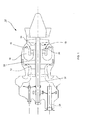
Fig. 1 is a schematic side cross-sectional view of a gas turbine engine; -
Fig. 2 is a schematic diagram of an adaptive fuel manifold filling system in accordance with an illustrative embodiment; -
Fig. 3 is a state diagram of an illustrative embodiment of a control unit ofFig. 2 ; -
Fig. 4 is a plot of a boosted fuel flow rate computed using the fuel manifold filling system ofFig. 2 , an acceleration recorded for the engine ofFig. 1 , and an overall fuel flow rate supplied to the engine ofFig. 1 in accordance with an illustrative embodiment; -
Fig. 5a is a flowchart of an adaptive fuel manifold filling method in accordance with an illustrative embodiment; -
Fig. 5b is a flowchart of the step ofFig. 5a of computing a boosted fuel flow rate; and -
Fig. 5c is a flowchart of the step ofFig. 5b of computing a multiplier. -
Fig.1 illustrates agas turbine engine 10 of a type preferably provided for use in subsonic flight, generally comprising in serial flow communication, acompressor section 12 for pressurizing the air, acombustor 14 in which the compressed air is mixed with fuel provided by amanifold 16 and ignited for generating an annular stream of hot combustion gases, and aturbine section 18 for extracting energy from the combustion gases. Theturbine section 18 includes acompressor turbine 20 in driving engagement with thecompressor section 12 through ahigh pressure shaft 22, and apower turbine 24 in driving engagement with apower shaft 26. Thepower shaft 26 is in driving engagement with anoutput shaft 28 through a reduction gearbox (not shown). - Referring to
Fig. 2 , an adaptive fuelmanifold filling system 100 will now be described. Thesystem 100 illustratively comprises acontrol unit 102 controlling the flow of fuel into thefuel manifold 16. Thecontrol unit 102 may comprise a digital computer or Engine Control Unit (ECU) (not shown) using a Central Processing Unit (CPU) (not shown). Thecontrol unit 102 may further be coupled to storage ormemory 104. Thememory 104 may be a main memory, such as a high speed Random Access Memory (RAM), or an auxiliary storage unit, such as a hard disk, an erasable programmable read only memory (EPROM), or flash memory (e.g. memory sticks and secure digital (SD) cards). Thememory 104 may further be any other type of memory, for example an optical storage media such as a videodisc and a compact disc. One or more databases (not shown) may be integrated directly into thememory 104 or may be provided separately therefrom. The databases may be provided as collections of data or information organized for rapid search and retrieval by a computer. The databases may be structured to facilitate storage, retrieval, modification, and deletion of data in conjunction with various data-processing operations. The databases may consist of a file or sets of files that can be broken down into records, each of which consists of one or more fields. Database information may be retrieved through queries using keywords and sorting commands, in order to rapidly search, rearrange, group, and select the field. The databases may be any organization of data on a data storage medium, such as one or more servers. - The
control unit 102 may be in communication with the hardware of theengine 10 and receive from at least onespeed sensor 106 coupled to theengine 10 measurements of the engine's gas generator speed (Ng). Thecontrol unit 102 may also be coupled to atemperature sensor 107 for detecting a light-up condition of theengine 10, as will be discussed further below. According to the received speed measurements, thecontrol unit 102 may be used to control the amount of fuel delivered to thefuel manifold 16 via fuel inlet pipes (not shown). For this purpose, thecontrol unit 102 illustratively uses an adaptive filling function to determine, in accordance with the currently received speed measurement, a suitable rate of fuel flow into thefuel manifold 16. In particular and as discussed further below, thecontrol unit 102 illustratively computes a boosted fuel flow rate that is to be used to fill thefuel manifold 16 for a predetermined duration and/or until engine ignition or light-up is achieved. The filling of thefuel manifold 16 may thus be precisely controlled so as to match the engine's gas generator speed, thereby improving the starting capability of theengine 10. By filling thefuel manifold 16 using the boosted fuel flow rate, the appropriate fuel/air ratio condition can be obtained for successful engine start by sending an appropriate amount of fuel to theengine combustor 14 at the correct compressor rotational speed. As will be discussed further below with reference toFig. 4 , thefuel manifold 16 is illustratively filled using a predetermined open loop schedule in addition to the boosted fuel flow rate determined by implementing the adaptive filling function logic. - Referring to
Fig. 3 , thecontrol unit 102 illustratively comprises areceiving module 108, anacceleration computation module 109, acomparison module 110, and a flowrate computation module 112. - In order to activate the implementation of the filling function, the
receiving module 108 may receive an input signal comprising an activation signal indicating that it is desired to enable the filling function. The activation signal may be received from the aircraft command system, i.e. from the pilot. Such an activation signal is illustratively the start signal of theengine 10, such that the filling function may be activated at every start of theengine 10. Further to receiving the activation signal, thereceiving module 108 illustratively receives from the speed sensor 106 a measurement of the engine's gas generator speed (Ng). Thereceiving module 108 may further retrieve from the memory 104 a value of the predetermined duration for which the filling function should be active. Thereceiving module 108 may then calculate the time that has elapsed between the moment the activation signal has been received and the present time. If the elapsed time is greater than the retrieved activation duration, thereceiving module 108 determines that the activation duration has lapsed and that the filling function should no longer be implemented by thecontrol unit 102. Thereceiving module 108 may then send a duration lapse signal to the flowrate computation module 112. The latter then retrieves a predetermined open-loop schedule from thememory 104 and generate an output signal indicating that fuel is to be supplied to thefuel manifold 16 according to an open-loop fuel flow rate. - If the receiving
module 108 determines that the activation duration has not lapsed, the receivingmodule 108 transmits the speed measurement to theacceleration computation module 109. Theacceleration computation module 109 may then compute from the received measurement the change rate of the engine's speed, i.e. the engine's acceleration (N2dot). Theacceleration computation module 109 computes the engine acceleration by taking the derivative of the speed and sends the computed acceleration to thecomparison module 110. - The
comparison module 110 then compares the received acceleration to a predetermined minimum acceleration threshold and a predetermined maximum acceleration threshold. The thresholds are illustratively stored in thememory 104 and may be retrieved by thecomparison module 110 for this purpose. Comparison of the computed acceleration to the threshold enables computation of a multiplier (BWf), which may be used to derive the boosted value of the fuel flow rate (Filling_Wf). Indeed, thecomparison module 110 determines whether the engine's acceleration is below the minimum threshold, above the maximum threshold, or between the minimum and the maximum threshold. The comparison result is then sent to the flowrate computation module 112, which determines therefrom the multiplier BWf and accordingly the boosted value of the fuel flow rate. - In particular, the multiplier BWf is illustratively defined as follows:

When [min_threshold] < N2dot < [max_threshold],

where the variable Max_N2dot corresponds to the maximum engine acceleration value recorded since the beginning of rotation of theengine 10. As discussed above, the engine acceleration is illustratively obtained from the speed measurements received from thespeed sensor 106. As such, these measurements may be received periodically from thespeed sensor 106 and stored over time in thememory 104 along with the corresponding values of the engine acceleration computed by theacceleration computation module 109. The value of Max_N2dot may therefore be obtained by searching in thememory 104 for the maximum one of the stored acceleration values. - The variables [max_threshold] and [min_threshold] respectively correspond to the predetermined maximum and minimum acceleration thresholds stored in the
memory 104 and retrieved therefrom by thecomparison module 110. In one embodiment, the variables [max_threshold] and [min_threshold] may vary as a function of altitude and outside air temperature. For example, at sea-level altitude and a temperature of -10 degrees Celsius, the maximum acceleration threshold may have a value of 4.2%Ng/sec while the minimum acceleration threshold may have a value of 3%Ng/sec. When an altitude of 20kft (6096m) is reached, the value of the maximum acceleration threshold may then become 5.8%Ng/sec while the value of the minimum acceleration threshold may become 3.4%Ng/sec. - Once the multiplier BWf has been determined on the basis of the comparison result received from the
comparison module 110, the flowrate computation module 112 may then compute the value of the boosted fuel flow rate Filling_Wf using the following equation:
where the variable [max_boost_Wf_value] corresponds to the upper limit, i.e. the maximum allowable value, for the boosted fuel flow rate. From equation (4), it can be seen that the boosted fuel flow rate is illustratively computed as a percentage of the maximum allowable boosted fuel flow rate [max_boost_Wf_value]. The value [max_boost_Wf_value] may be predetermined and stored in thememory 104 for subsequent retrieval by thecomparison module 110 to compute the boosted fuel flow rate Filling_Wf. In one embodiment, [max_boost_Wf_value] is set to 60PPH. It should however be understood that other values may apply. - Once the boosted fuel flow rate Filling_Wf has been determined, the flow
rate computation module 112 generates an output signal accordingly, the output signal indicative of the boosted fuel flow rate that is to be sent via the fuel inlet pipes to thefuel manifold 16 for filling the latter. Since this boosted fuel flow rate is computed on the basis of the engine's speed received at thecontrol unit 102, thefuel manifold 16 may be filled on time to match the speed of theengine 10 using the adaptive filling function described above. As a result, appropriate fuel/air ratio conditions can be created and successful engine light-up achieved. -
Fig. 4 illustrates aplot 200 of the fuel flow rate computed upon thecontrol unit 102 implementing the adaptive filling function logic, aplot 202 of the acceleration of theengine 10, and aplot 204 of the overall fuel flow rate supplied to theengine 10 subsequent to implementation of the adaptive filling function logic, all as a function of the speed of theengine 10. - The
control unit 102 may implement the adaptive filling function by default. As is apparent from equations (1) to (3) and as can be seen fromplot 200, the adaptive filling function may be used to adjust the fuel flow rate as soon as the engine's acceleration (N2dot) is greater than the minimum acceleration threshold [min_threshold], i.e. the multiplier BWf is non-zero. The adaptive filling function may be enabled for any type of engine start-up. For example, thecontrol unit 102 may implement the adaptive filling function logic prior to or during flight. As discussed above, the adaptive filling function may further be enabled over a fixed duration, e.g. 1.20 seconds, in addition to carrying out the open-loop fuel schedule. Such a schedule may be used to specify a predetermined amount of fuel to be delivered to thefuel manifold 16 for a particular operating condition of theengine 10. The open loop schedule can be used to provide precise fuel injection timing and regulation using a fixed calculation or function developed by careful measurement and data taken from arepresentative engine 10. As discussed above, the open-loop schedule may be stored in thememory 104 and retrieved therefrom by the flowrate computation module 112 of thecontrol unit 102 in order to determine the fuel flow rate to be delivered to thefuel manifold 16 according to the schedule. - Referring back to
Figure 3 in addition toFigure 4 , thecontrol unit 102 may further disable the adaptive filling function upon the detection of engine light-up. Such detection may, for example, be accomplished by thecontrol unit 102 checking an output signal generated by the temperature sensor (reference 107 inFigure 2 ) capable of detecting exhaust gas temperature. The signal output by thetemperature sensor 107 illustratively comprises an exhaust gas temperature measurement and may be received at the receivingmodule 108 of thecontrol unit 102. The receivingmodule 108 may then determine from the received signal, i.e. the temperature measurement, whether engine light-up has occurred. For example, this may be effected by comparing the received temperature measurement to a temperature threshold retrieved from thememory 104. It should be understood that light-up detection may be effected in a variety of other ways known to those skilled in the art. Once the receivingmodule 108 determines that light-up has occurred, a light-up detection signal may be transmitted to the flowrate computation module 112, which will determine the appropriate fuel flow rate to be delivered to thefuel manifold 16. - In particular, if light-up is detected after the lapse of the fixed duration during which the filling function is enabled, the
control unit 102 has illustratively already automatically returned to the open-loop schedule at the time the light-up is detected. Indeed, in this case, a duration lapse signal has illustratively already been received at the flowrate computation module 112 prior to receiving the light-up detection signal. As discussed above, upon receiving the duration lapse signal, the flowrate computation module 112 will illustratively have retrieved the open-loop schedule from thememory 104 and generated an output signal indicating that the fuel flow rate sent to thefuel manifold 16 is to follow the retrieved open-loop schedule. Upon subsequently receiving the light-up detection signal from the receivingmodule 108, the flowrate computation module 112 may then determine that the current fuel flow rate already follows the previously retrieved open-loop schedule and no additional action needs to be taken to adjust the fuel flow rate. Otherwise, if light-up is detected before the lapse of the fixed duration, the filling function is disabled and thecontrol unit 102 returns to the open-loop schedule at that time (see plot 204). For this purpose, upon receiving the light-up detection signal, the flowrate computation module 112 illustratively retrieves the open-loop schedule from thememory 104 and outputs a signal indicating that the fuel flow rate is to follow the retrieved open-loop schedule. - Whenever returning to the open-loop schedule, the flow
rate computation module 112 illustratively computes a gradual step down in fuel flow to achieve a smooth transition. This gradual step down may be performed over a range of 3% of the gas generator speed (Ng). For instance, if the speed of theengine 10 had reached 10,000 rpm at light-up, the filling function is illustratively disabled and the fuel flow rate is gradually lowered towards the open-loop fuel flow rate over the range of speeds from 10,000 rpm to 10,000 rpm + 3% of 10,000 rpm, i.e. 10,300 rpm. It should be understood that ranges other then 3% Ng may also be used. - The above is illustrated in
plot 204, which shows that, upon the adaptive filling function being enabled, the boosted fuel flow rate computed by the flowrate computation module 112 is added to the predetermined open loop fuel schedule over the fixed duration. In particular, upon activation of the filling function, fuel is illustratively delivered to thefuel manifold 16 according to a flow rate equal to the sum of the boosted fuel flow rate (Wf) computed using equation (4) and a fuel flow rate determined by the open-loop schedule. Upon either light-up detection, and accordingly disablement of the filling function, or lapse of the fixed duration, thefuel manifold 16 may be filled according to the open-loop fuel flow rate only. - The fuel flow rate supplied to the
fuel manifold 16 may further vary according to the starter torque. Indeed, during normal engine start, the compressor rotational speed is illustratively obtained through the use of a motive power source, such as an electrical or pneumatic starter (not shown) drivably coupled to theengine 10 and operated to produce rotation thereof. As the starter accelerates theengine 10, a fuel delivery pump and an igniter (not shown) may be actuated to effect ignition in thecombustor 14. Upon successful ignition of theengine 10 and once theengine 10 has reached a self-sustaining speed, the starter may be disengaged. The starter torque may however vary, producing different engine core accelerations as shown inplot 202. Using the minimum allowable starter torque, lower acceleration may be achieved, and accordingly lower fuel flow rates may be supplied to thefuel manifold 16, as shown in the lower curves illustrated inplots plots - It should be understood that the adaptive filling function implemented by the
control unit 102 may not only adapt to starter torque variations but to other parameters as well. Indeed, various conditions may produce changes in the rotor acceleration. Such conditions include, but are not limited to, starter torque variations, A/C forward speed in case of in-flight re-start of theengine 10, ambient air temperature, engine oil temperature, and aircraft battery depletion. For example, an increase in ambient air temperature or engine oil temperature can result in an increase in rotor acceleration. Also, a low battery may result in low starter torque, leading to low acceleration. By taking into account to the rotor acceleration, the adaptive filling function implemented by thecontrol unit 102 can therefore adapt to these different conditions. - Referring to
Fig. 5a , amethod 300 for adaptively filling thefuel manifold 16 will now be described. Themethod 300 comprises receiving atstep 302 an activation signal. The predetermined duration for which it is desired to activate the filling function may further be retrieved atstep 304. A measurement of a speed of theengine 10 from thespeed sensor 106 may then be received atstep 306. Upon receiving the speed measurement, themethod 300 may determine atstep 308 whether the activation duration has lapsed. If this is the case, the open-loop schedule may be applied atstep 310. Otherwise, themethod 300 may determine atstep 312 whether light-up of theengine 10 has been detected. If this is the case, themethod 300 may flow to thestep 310 of applying the open-loop schedule. Otherwise, the acceleration of theengine 10 may be computed atstep 314 from the received speed measurement. The boosted fuel flow rate may further be computed atstep 316 and added to the open-loop schedule atstep 318 for filling thefuel manifold 16 accordingly, as discussed above. Themethod 300 may then flow back to thestep 306 of receiving a speed measurement and the process may be repeated. - Referring to
Fig. 5b , thestep 316 of computing the boost fuel flow rate illustratively comprises retrieving at step 320 a maximum recorded engine acceleration (Max_N2dot) and minimum and maximum acceleration thresholds (min_threshold and max_threshold). Thestep 316 further comprises comparing atstep 322 the acceleration computed atstep 314 to the thresholds retrieved atstep 320. The multiplier (BWf) may then be computed atstep 324 on the basis of the comparison result. In particular,step 324 illustratively comprises determining the multiplier according to equations (1), (2), and (3) discussed above. Thestep 316 may further comprise retrieving a maximum boosted fuel flow rate (max_boost_Wf_value) atstep 326 and multiplying atstep 328 the retrieved maximum boosted fuel flow rate by the multiplier computed atstep 324. The multiplication performed atstep 328 is illustratively effected according to equation (4) discussed above. - Referring to
Fig. 5c , as discussed above with reference to equations (1), (2), and (3), thestep 324 of computing the multiplier illustratively comprises determining atstep 330 whether the acceleration computed atstep 314 is lower than the minimum acceleration threshold. If this is the case, themethod 300 flows to thestep 332 of setting the multiplier to zero. Otherwise, themethod 300 flows to thestep 334 of determining whether the acceleration computed atstep 314 is greater than the maximum acceleration threshold. If this is the case, the multiplier is set to one atstep 336. Otherwise, the method computes atstep 338 the difference between the maximum recorded engine acceleration and the minimum acceleration threshold, computes the difference between the maximum acceleration threshold and the minimum acceleration threshold atstep 340, and computes at step 342 a ratio of the differences to determine a value of the multiplier. - The above description is meant to be exemplary only, and one skilled in the art will recognize that changes may be made to the embodiments described without departing from the scope of the invention disclosed. Modifications which fall within the scope of the present invention will be apparent to those skilled in the art, in light of a review of this disclosure, and such modifications are intended to fall within the appended claims.
Claims (15)
- A system for filling a fuel manifold (16) of an engine (10), the system comprising:a memory (104);a receiving unit (108) adapted to receive a present measurement of a speed of the engine; anda processing unit coupled to the memory (104), the processing unit adapted to compute from the received measurement a flow rate of fuel to be supplied to the fuel manifold (16) for filling thereof and to generate an output signal for causing delivery of the fuel to the fuel manifold (16) according to the computed flow rate.
- The system of claim 1, wherein the memory (104) has stored therein a minimum acceleration threshold and a maximum acceleration threshold and further wherein the processing unit is adapted to compute from the received measurement a present value of an acceleration of the engine, retrieve the minimum acceleration threshold and the maximum acceleration threshold from the memory, compare the present value of the acceleration to the retrieved minimum acceleration threshold and maximum acceleration threshold, and compute the flow rate according to a result of the comparison.
- The system of claim 2, wherein the processing unit is adapted to compute the flow rate by computing a boosted fuel flow rate and adding the boosted fuel flow rate to a predetermined fuel flow rate, the predetermined fuel flow rate following an open-loop fuel flow schedule, and optionally wherein the processing unit is adapted to compute the flow rate by adding the boosted fuel flow rate to the predetermined fuel flow rate until a detection of a light-up of the engine.
- The system of claim 3, wherein, upon the detection of the light-up, the processing unit is adapted to transition the flow rate towards the predetermined fuel flow rate.
- The system of claim 3 or 4, wherein the memory (104) has stored therein a maximum allowable value for the boosted fuel flow rate and further wherein the processing unit is adapted to retrieve the maximum allowable value from the memory and to multiply the retrieved maximum allowable value by a multiplier to compute the boosted fuel flow rate, and optionally wherein, if the result of the comparison indicates that the present value of the acceleration is lower than the minimum acceleration threshold, the processing unit sets the multiplier to be equal to zero and if the result of the comparison indicates that the present value of the acceleration is greater than the maximum acceleration threshold, the processing unit sets the multiplier to be equal to one.
- The system of claim 5, wherein the memory (104) has stored therein a plurality of previous values of the acceleration and further wherein the processing unit is adapted to search the memory (104) for a maximum one of the plurality of previous values.
- The system of claim 6, wherein, if the result of the comparison indicates that the present value of the acceleration is greater than the minimum acceleration threshold and lower than the maximum acceleration threshold, the processing unit computes a first difference between the maximum acceleration value and the minimum acceleration threshold, computes a second difference between the maximum acceleration threshold and the minimum acceleration threshold, computes a ratio of the first difference and the second difference, and sets the multiplier to be equal to the ratio.
- A method for filling a fuel manifold (16) of an engine (10), the method comprising:receiving a present measurement of a speed of the engine;computing from the received measurement a flow rate of fuel to be supplied to the fuel manifold for filling thereof; andgenerating an output signal for causing delivery of the fuel to the fuel manifold according to the computed flow rate.
- The method of claim 8, further comprising computing from the received measurement a present value of an acceleration of the engine, retrieving from a memory (104) a minimum acceleration threshold and a maximum acceleration threshold, comparing the present value of the acceleration to the retrieved minimum acceleration threshold and maximum acceleration threshold, and computing the flow rate according to a result of the comparison.
- The method of claim 9, wherein computing the flow rate comprises computing a boosted fuel flow rate and adding the boosted fuel flow rate to a predetermined fuel flow rate, the predetermined fuel flow rate following an open-loop fuel flow schedule, and optionally wherein computing the flow rate comprises computing a boosted fuel flow rate and adding the boosted fuel flow rate to the predetermined fuel flow rate until a detection of a light-up of the engine.
- The method of claim 10, further comprising transitioning the flow rate towards the predetermined fuel flow rate upon the detection of the light-up of the engine.
- The method of claim 10 or 11, wherein computing the boosted fuel flow rate comprises retrieving a maximum allowable value for the boosted fuel flow rate from the memory and multiplying the retrieved maximum allowable value by a multiplier, and optionally wherein comparing the present value of the acceleration to the retrieved minimum acceleration threshold and maximum acceleration threshold comprises setting the multiplier to be equal to zero if the result of the comparison indicates that the present value of the acceleration is lower than the minimum acceleration threshold and setting the multiplier to be equal to one if the result of the comparison indicates that the present value of the acceleration is greater than the maximum acceleration threshold.
- The method of claim 12, wherein comparing the present value of the acceleration to the retrieved minimum acceleration threshold and maximum acceleration threshold comprises searching for a maximum one of a plurality of previous values of the acceleration stored in the memory.
- The method of claim 13, wherein comparing the present value of the acceleration to the retrieved minimum acceleration threshold and maximum acceleration threshold comprises, if the result of the comparison indicates that the present value of the acceleration is greater than the minimum acceleration threshold and lower than the maximum acceleration threshold, computing a first difference between the maximum acceleration value and the minimum acceleration threshold, computing a second difference between the maximum acceleration threshold and the minimum acceleration threshold, computing a ratio of the first difference and the second difference, and setting the multiplier to be equal to the ratio.
- A system for filling a fuel manifold (16) of an engine (10), the system comprising:means for receiving a present measurement of a speed of the engine;means for computing from the received measurement a flow rate of fuel to be supplied to the fuel manifold for filling thereof; andmeans for generating an output signal for causing delivery of the fuel to the fuel manifold according to the computed flow rate.
Applications Claiming Priority (1)
| Application Number | Priority Date | Filing Date | Title |
|---|---|---|---|
| US13/630,679 US9541005B2 (en) | 2012-09-28 | 2012-09-28 | Adaptive fuel manifold filling function for improved engine start |
Publications (3)
| Publication Number | Publication Date |
|---|---|
| EP2713028A2 true EP2713028A2 (en) | 2014-04-02 |
| EP2713028A3 EP2713028A3 (en) | 2017-03-29 |
| EP2713028B1 EP2713028B1 (en) | 2020-11-04 |
Family
ID=48782170
Family Applications (1)
| Application Number | Title | Priority Date | Filing Date |
|---|---|---|---|
| EP13173972.4A Active EP2713028B1 (en) | 2012-09-28 | 2013-06-27 | Adaptive fuel manifold filling function for improved engine start |
Country Status (2)
| Country | Link |
|---|---|
| US (1) | US9541005B2 (en) |
| EP (1) | EP2713028B1 (en) |
Families Citing this family (6)
| Publication number | Priority date | Publication date | Assignee | Title |
|---|---|---|---|---|
| US11015535B2 (en) * | 2018-02-27 | 2021-05-25 | Raytheon Technologies Corporation | Light-off detection for gas turbine engines |
| US11300054B2 (en) * | 2018-11-08 | 2022-04-12 | Pratt & Whitney Canada Corp. | Fuel flow control system and method for engine start |
| US11760500B2 (en) | 2019-11-11 | 2023-09-19 | Pratt & Whitney Canada Corp. | Systems and methods for filling a fuel manifold of a gas turbine engine |
| GB2618295B (en) * | 2021-03-26 | 2025-04-16 | Mitsubishi Heavy Ind Ltd | Gas turbine system and control method therefor |
| US12428997B2 (en) | 2024-01-23 | 2025-09-30 | Rtx Corporation | Multi-mode starter control for gas turbine engines |
| US12366360B1 (en) * | 2024-04-29 | 2025-07-22 | Pratt & Whitney Canada Corp. | Gas turbine adaptive secondary fuel filling profile |
Family Cites Families (60)
| Publication number | Priority date | Publication date | Assignee | Title |
|---|---|---|---|---|
| US2880790A (en) * | 1951-08-10 | 1959-04-07 | Bendix Aviat Corp | Starting fuel control for gas turbine engines |
| US3967598A (en) * | 1971-06-30 | 1976-07-06 | The Bendix Corporation | Combined electric fuel pump control circuit intermittent injection electronic fuel control systems |
| FR2449795B1 (en) * | 1979-02-24 | 1986-11-28 | Huber Motorenbau Inst | INJECTION SYSTEM FOR INTERNAL COMBUSTION ENGINE |
| US4627234A (en) * | 1983-06-15 | 1986-12-09 | Sundstrand Corporation | Gas turbine engine/load compressor power plants |
| GB2174147B (en) * | 1985-04-25 | 1989-02-01 | Rolls Royce | Improvements in or relating to the operation of gas turbine engine fuel systems |
| US4815278A (en) * | 1987-10-14 | 1989-03-28 | Sundstrand Corporation | Electrically driven fuel pump for gas turbine engines |
| US4901701A (en) * | 1987-11-12 | 1990-02-20 | Injection Research Specialists, Inc. | Two-cycle engine with electronic fuel injection |
| JPH01142545U (en) * | 1988-03-25 | 1989-09-29 | ||
| US4922710A (en) * | 1989-01-04 | 1990-05-08 | General Electric Company | Integrated boost compressor/gas turbine control |
| US5020314A (en) * | 1989-06-19 | 1991-06-04 | Williams International Corporation | Multiple fluid speed systems |
| US5107674A (en) * | 1990-03-30 | 1992-04-28 | General Electric Company | Control for a gas turbine engine |
| JPH04194341A (en) * | 1990-11-27 | 1992-07-14 | Mazda Motor Corp | Fuel controller f0r engine |
| US5175994A (en) * | 1991-05-03 | 1993-01-05 | United Technologies Corporation | Combustion section supply system having fuel and water injection for a rotary machine |
| US5274996A (en) * | 1991-10-11 | 1994-01-04 | Allied-Signal, Inc. | Closed loop fuel control system |
| JP3658415B2 (en) * | 1993-12-28 | 2005-06-08 | 株式会社 日立インダストリイズ | Gas turbine equipment |
| FR2718793B1 (en) * | 1994-04-13 | 1996-05-24 | Snecma | Fuel injector fuel supply system. |
| IT1281303B1 (en) * | 1995-03-28 | 1998-02-17 | Elasis Sistema Ricerca Fiat | DEVICE FOR REGULATING THE SUPPLY PRESSURE OF A FLUID IN A PRESSURE FLUID ACCUMULATOR, FOR EXAMPLE FOR |
| JPH09170467A (en) * | 1995-12-20 | 1997-06-30 | Denso Corp | Fuel supply device for internal combustion engine |
| US5966925A (en) * | 1996-04-26 | 1999-10-19 | Kabushiki Kaisha Toshiba | Gas turbine power plant control for starting and stopping |
| US6092509A (en) * | 1998-11-19 | 2000-07-25 | Mitsubishi Jidosha Kogyo Kabushiki Kaisha | Accumulator type fuel injection system |
| US6357219B1 (en) * | 1998-12-11 | 2002-03-19 | Alliedsignal Inc. | Turbine engine fuel control system |
| US6182438B1 (en) * | 1999-07-08 | 2001-02-06 | Moog Inc. | Method and apparatus for starting a gas turbine engine |
| EP1079179B1 (en) * | 1999-08-21 | 2004-11-24 | Rolls-Royce Deutschland Ltd & Co KG | Process for adapting the operating condition of a gas-turbine staged combustion chamber |
| JP2001182597A (en) * | 1999-12-24 | 2001-07-06 | Hitachi Ltd | High pressure fuel pump controller and in-cylinder injection engine controller |
| US6321525B1 (en) * | 2000-02-03 | 2001-11-27 | Rolls-Royce Corporation | Overspeed detection techniques for gas turbine engine |
| US6810676B2 (en) * | 2001-12-14 | 2004-11-02 | Pratt & Whitney Canada Corp. | Method of engine starting in a gas turbine engine |
| WO2003060303A1 (en) * | 2002-01-09 | 2003-07-24 | Ebara Corporation | A gas turbine apparatus and a starting method thereof |
| US6786049B2 (en) * | 2002-05-22 | 2004-09-07 | Hamilton Sundstrand | Fuel supply control for a gas turbine including multiple solenoid valves |
| WO2004053312A1 (en) * | 2002-12-12 | 2004-06-24 | Ebara Corporation | Gas turbine apparatus |
| US7200985B2 (en) * | 2003-07-15 | 2007-04-10 | Honeywell International Inc. | Fuel delivery system having an ecology valve |
| US7010399B2 (en) * | 2003-11-24 | 2006-03-07 | The Boeing Company | Methods and apparatus for fuel control using inertial measurement data |
| US7168254B2 (en) * | 2004-02-17 | 2007-01-30 | Honeywell International Inc. | Control logic for fuel controls on APUs |
| FR2869642B1 (en) * | 2004-04-28 | 2006-07-21 | Eurocopter France | DEVICE AND METHOD FOR REGULATING ACCELERATION OR DECELERATION OF THE FLOW RATE OF A TURBOMOTING FUEL |
| JP4221332B2 (en) * | 2004-05-12 | 2009-02-12 | 三菱電機株式会社 | Fuel injection control device for internal combustion engine |
| US20060030450A1 (en) * | 2004-08-09 | 2006-02-09 | Kyle Ronald L | Hybrid vehicle formed by converting a conventional IC engine powered vehicle and method of such conversion |
| US20100044129A1 (en) * | 2004-08-09 | 2010-02-25 | Hybrid Electric Conversion Co., Llc | Hybrid vehicle formed by converting a conventional ic engine powered vehicle and method of such conversion |
| US7509812B2 (en) * | 2004-08-20 | 2009-03-31 | Hamilton Sundstrand Corporation | Dual ignition system for a gas turbine engine |
| US7386982B2 (en) * | 2004-10-26 | 2008-06-17 | General Electric Company | Method and system for detecting ignition failure in a gas turbine engine |
| US20090145105A1 (en) * | 2004-12-01 | 2009-06-11 | Suciu Gabriel L | Remote engine fuel control and electronic engine control for turbine engine |
| JP4906848B2 (en) * | 2005-06-01 | 2012-03-28 | ルノー・エス・アー・エス | Control method for internal combustion engine |
| JP4050287B2 (en) * | 2005-08-10 | 2008-02-20 | 三菱電機株式会社 | Energy-saving high-pressure fuel supply control system for internal combustion engines |
| US7540141B2 (en) * | 2005-12-13 | 2009-06-02 | Hamilton Sundstrand Corporation | Smart fuel control system |
| US7549293B2 (en) * | 2006-02-15 | 2009-06-23 | General Electric Company | Pressure control method to reduce gas turbine fuel supply pressure requirements |
| US7726112B2 (en) * | 2006-04-24 | 2010-06-01 | Pratt & Whitney Canada Corp. | Fuel system of gas turbine engines |
| EP1860302A1 (en) * | 2006-05-22 | 2007-11-28 | Siemens Aktiengesellschaft | Gas turbine engine starting method and control device |
| JP4333709B2 (en) * | 2006-08-10 | 2009-09-16 | 株式会社日立製作所 | In-cylinder injection internal combustion engine control device |
| GB2443194B (en) * | 2006-10-24 | 2008-09-10 | Rolls-Royce Plc | Gas turbine engine |
| US7406949B2 (en) * | 2006-11-06 | 2008-08-05 | Caterpillar Inc. | Selective displacement control of multi-plunger fuel pump |
| US7841184B2 (en) * | 2007-04-19 | 2010-11-30 | Pratt & Whitney Canada Corp. | Start flow measurement |
| US7861534B2 (en) * | 2007-05-03 | 2011-01-04 | Pratt & Whitney Canada Corp. | Method of starting turbine engine from low engine speed |
| US7841164B2 (en) * | 2007-09-19 | 2010-11-30 | Honeywell International Inc. | Direct metering fuel system with an integral redundant motor pump |
| US8200410B2 (en) * | 2008-03-12 | 2012-06-12 | Delavan Inc | Active pattern factor control for gas turbine engines |
| US8316630B2 (en) * | 2008-08-27 | 2012-11-27 | Honeywell International Inc. | Flow equalizing override assembly for fuel divider system |
| US8286432B2 (en) * | 2008-11-25 | 2012-10-16 | Honeywell International Inc. | Electric power generating turbine engine fuel supply system |
| US7938101B2 (en) * | 2009-02-11 | 2011-05-10 | GM Global Technology Operations LLC | Adaptive control of fuel delivery in direct injection engines |
| US8245517B2 (en) * | 2009-05-19 | 2012-08-21 | Hamilton Sundstrand Corporation | Gas turbine starting with stepping speed control |
| JP2011043136A (en) * | 2009-08-24 | 2011-03-03 | Honda Motor Co Ltd | Fuel control device at starting of gas turbine engine |
| US9388753B2 (en) * | 2009-09-17 | 2016-07-12 | General Electric Company | Generator control having power grid communications |
| US8925328B2 (en) * | 2009-10-26 | 2015-01-06 | Siemens Energy, Inc. | Gas turbine starting process |
| US8463451B2 (en) * | 2010-04-19 | 2013-06-11 | General Electric Company | Automatic primary frequency response contribution monitoring system and method |
-
2012
- 2012-09-28 US US13/630,679 patent/US9541005B2/en active Active
-
2013
- 2013-06-27 EP EP13173972.4A patent/EP2713028B1/en active Active
Non-Patent Citations (1)
| Title |
|---|
| None |
Also Published As
| Publication number | Publication date |
|---|---|
| EP2713028A3 (en) | 2017-03-29 |
| US20140095051A1 (en) | 2014-04-03 |
| US9541005B2 (en) | 2017-01-10 |
| EP2713028B1 (en) | 2020-11-04 |
Similar Documents
| Publication | Publication Date | Title |
|---|---|---|
| EP2713028B1 (en) | Adaptive fuel manifold filling function for improved engine start | |
| EP2893169B1 (en) | Method and system for starting an aircraft turboengine | |
| EP3208429B1 (en) | System and method for starting a twin motor aircraft | |
| EP3850202B1 (en) | Method for controlling a turbomachine comprising an electric motor | |
| EP2609313B1 (en) | Method for optimizing the control of a free turbine powerplant for an aircraft, and controller for implementing same | |
| EP3401530B1 (en) | Method and system for setting an acceleration schedule for engine start | |
| US7861534B2 (en) | Method of starting turbine engine from low engine speed | |
| US10094292B2 (en) | Method of acceleration control during APU starting | |
| WO2016030616A1 (en) | Device and method for starting a gas turbine, method for regulating the rotational speed of a gas turbine, and associated gas turbine and turbine engine | |
| RU2630068C2 (en) | Way and adjustment element of the target value of the parameter that affect on gas-turbine engine draft | |
| EP3712074B1 (en) | Method and system for setting power of an aircraft engine | |
| EP3199784B1 (en) | Fuel flow control | |
| FR3108139A1 (en) | Method of controlling a turbomachine comprising an electric machine | |
| EP2297442B1 (en) | Method and apparatus for providing fuel to an aircraft engine | |
| CA2791563C (en) | Adaptive fuel manifold filling function for improved engine start | |
| EP3530911B1 (en) | Light-off detection for gas turbine engines | |
| FR3074836A1 (en) | METHOD FOR DETECTION OF TURBOMACHINE IGNITION | |
| EP3333393A1 (en) | Method and device for controlling extractions from a turbine engine to reduce the risk of pumping by information exchange between an energy manager and a system for controlling the turbine engine | |
| EP4355990B1 (en) | Aircraft propulsion system with start-up control device | |
| RU2310100C2 (en) | Method to protect gas-turbine engine from unstable operation of compressor | |
| WO2023007076A1 (en) | Transfer of power between the high-pressure shaft and the low-pressure shaft of a turbomachine | |
| EP2382387B1 (en) | System and method for monitoring the start of an internal combustion engine | |
| CN110886656A (en) | Method and system for setting acceleration schedule for engine start | |
| WO2026037686A1 (en) | Method for controlling a turbine engine comprising an electric machine | |
| WO2026052926A1 (en) | Method for controlling a hybrid turbine engine |
Legal Events
| Date | Code | Title | Description |
|---|---|---|---|
| PUAI | Public reference made under article 153(3) epc to a published international application that has entered the european phase |
Free format text: ORIGINAL CODE: 0009012 |
|
| AK | Designated contracting states |
Kind code of ref document: A2 Designated state(s): AL AT BE BG CH CY CZ DE DK EE ES FI FR GB GR HR HU IE IS IT LI LT LU LV MC MK MT NL NO PL PT RO RS SE SI SK SM TR |
|
| AX | Request for extension of the european patent |
Extension state: BA ME |
|
| PUAL | Search report despatched |
Free format text: ORIGINAL CODE: 0009013 |
|
| AK | Designated contracting states |
Kind code of ref document: A3 Designated state(s): AL AT BE BG CH CY CZ DE DK EE ES FI FR GB GR HR HU IE IS IT LI LT LU LV MC MK MT NL NO PL PT RO RS SE SI SK SM TR |
|
| AX | Request for extension of the european patent |
Extension state: BA ME |
|
| RIC1 | Information provided on ipc code assigned before grant |
Ipc: F02C 9/20 20060101ALI20170218BHEP Ipc: F02C 9/28 20060101AFI20170218BHEP Ipc: F02C 7/26 20060101ALI20170218BHEP |
|
| STAA | Information on the status of an ep patent application or granted ep patent |
Free format text: STATUS: REQUEST FOR EXAMINATION WAS MADE |
|
| 17P | Request for examination filed |
Effective date: 20170929 |
|
| RBV | Designated contracting states (corrected) |
Designated state(s): AL AT BE BG CH CY CZ DE DK EE ES FI FR GB GR HR HU IE IS IT LI LT LU LV MC MK MT NL NO PL PT RO RS SE SI SK SM TR |
|
| GRAP | Despatch of communication of intention to grant a patent |
Free format text: ORIGINAL CODE: EPIDOSNIGR1 |
|
| STAA | Information on the status of an ep patent application or granted ep patent |
Free format text: STATUS: GRANT OF PATENT IS INTENDED |
|
| INTG | Intention to grant announced |
Effective date: 20200514 |
|
| GRAS | Grant fee paid |
Free format text: ORIGINAL CODE: EPIDOSNIGR3 |
|
| GRAA | (expected) grant |
Free format text: ORIGINAL CODE: 0009210 |
|
| STAA | Information on the status of an ep patent application or granted ep patent |
Free format text: STATUS: THE PATENT HAS BEEN GRANTED |
|
| AK | Designated contracting states |
Kind code of ref document: B1 Designated state(s): AL AT BE BG CH CY CZ DE DK EE ES FI FR GB GR HR HU IE IS IT LI LT LU LV MC MK MT NL NO PL PT RO RS SE SI SK SM TR |
|
| REG | Reference to a national code |
Ref country code: GB Ref legal event code: FG4D |
|
| REG | Reference to a national code |
Ref country code: CH Ref legal event code: EP |
|
| REG | Reference to a national code |
Ref country code: AT Ref legal event code: REF Ref document number: 1331106 Country of ref document: AT Kind code of ref document: T Effective date: 20201115 |
|
| REG | Reference to a national code |
Ref country code: DE Ref legal event code: R096 Ref document number: 602013073746 Country of ref document: DE |
|
| REG | Reference to a national code |
Ref country code: IE Ref legal event code: FG4D |
|
| REG | Reference to a national code |
Ref country code: NL Ref legal event code: MP Effective date: 20201104 |
|
| REG | Reference to a national code |
Ref country code: AT Ref legal event code: MK05 Ref document number: 1331106 Country of ref document: AT Kind code of ref document: T Effective date: 20201104 |
|
| PG25 | Lapsed in a contracting state [announced via postgrant information from national office to epo] |
Ref country code: FI Free format text: LAPSE BECAUSE OF FAILURE TO SUBMIT A TRANSLATION OF THE DESCRIPTION OR TO PAY THE FEE WITHIN THE PRESCRIBED TIME-LIMIT Effective date: 20201104 Ref country code: RS Free format text: LAPSE BECAUSE OF FAILURE TO SUBMIT A TRANSLATION OF THE DESCRIPTION OR TO PAY THE FEE WITHIN THE PRESCRIBED TIME-LIMIT Effective date: 20201104 Ref country code: PT Free format text: LAPSE BECAUSE OF FAILURE TO SUBMIT A TRANSLATION OF THE DESCRIPTION OR TO PAY THE FEE WITHIN THE PRESCRIBED TIME-LIMIT Effective date: 20210304 Ref country code: NO Free format text: LAPSE BECAUSE OF FAILURE TO SUBMIT A TRANSLATION OF THE DESCRIPTION OR TO PAY THE FEE WITHIN THE PRESCRIBED TIME-LIMIT Effective date: 20210204 Ref country code: GR Free format text: LAPSE BECAUSE OF FAILURE TO SUBMIT A TRANSLATION OF THE DESCRIPTION OR TO PAY THE FEE WITHIN THE PRESCRIBED TIME-LIMIT Effective date: 20210205 |
|
| PG25 | Lapsed in a contracting state [announced via postgrant information from national office to epo] |
Ref country code: LV Free format text: LAPSE BECAUSE OF FAILURE TO SUBMIT A TRANSLATION OF THE DESCRIPTION OR TO PAY THE FEE WITHIN THE PRESCRIBED TIME-LIMIT Effective date: 20201104 Ref country code: PL Free format text: LAPSE BECAUSE OF FAILURE TO SUBMIT A TRANSLATION OF THE DESCRIPTION OR TO PAY THE FEE WITHIN THE PRESCRIBED TIME-LIMIT Effective date: 20201104 Ref country code: IS Free format text: LAPSE BECAUSE OF FAILURE TO SUBMIT A TRANSLATION OF THE DESCRIPTION OR TO PAY THE FEE WITHIN THE PRESCRIBED TIME-LIMIT Effective date: 20210304 Ref country code: SE Free format text: LAPSE BECAUSE OF FAILURE TO SUBMIT A TRANSLATION OF THE DESCRIPTION OR TO PAY THE FEE WITHIN THE PRESCRIBED TIME-LIMIT Effective date: 20201104 Ref country code: ES Free format text: LAPSE BECAUSE OF FAILURE TO SUBMIT A TRANSLATION OF THE DESCRIPTION OR TO PAY THE FEE WITHIN THE PRESCRIBED TIME-LIMIT Effective date: 20201104 Ref country code: AT Free format text: LAPSE BECAUSE OF FAILURE TO SUBMIT A TRANSLATION OF THE DESCRIPTION OR TO PAY THE FEE WITHIN THE PRESCRIBED TIME-LIMIT Effective date: 20201104 Ref country code: BG Free format text: LAPSE BECAUSE OF FAILURE TO SUBMIT A TRANSLATION OF THE DESCRIPTION OR TO PAY THE FEE WITHIN THE PRESCRIBED TIME-LIMIT Effective date: 20210204 |
|
| REG | Reference to a national code |
Ref country code: LT Ref legal event code: MG9D |
|
| PG25 | Lapsed in a contracting state [announced via postgrant information from national office to epo] |
Ref country code: HR Free format text: LAPSE BECAUSE OF FAILURE TO SUBMIT A TRANSLATION OF THE DESCRIPTION OR TO PAY THE FEE WITHIN THE PRESCRIBED TIME-LIMIT Effective date: 20201104 |
|
| PG25 | Lapsed in a contracting state [announced via postgrant information from national office to epo] |
Ref country code: SK Free format text: LAPSE BECAUSE OF FAILURE TO SUBMIT A TRANSLATION OF THE DESCRIPTION OR TO PAY THE FEE WITHIN THE PRESCRIBED TIME-LIMIT Effective date: 20201104 Ref country code: RO Free format text: LAPSE BECAUSE OF FAILURE TO SUBMIT A TRANSLATION OF THE DESCRIPTION OR TO PAY THE FEE WITHIN THE PRESCRIBED TIME-LIMIT Effective date: 20201104 Ref country code: LT Free format text: LAPSE BECAUSE OF FAILURE TO SUBMIT A TRANSLATION OF THE DESCRIPTION OR TO PAY THE FEE WITHIN THE PRESCRIBED TIME-LIMIT Effective date: 20201104 Ref country code: CZ Free format text: LAPSE BECAUSE OF FAILURE TO SUBMIT A TRANSLATION OF THE DESCRIPTION OR TO PAY THE FEE WITHIN THE PRESCRIBED TIME-LIMIT Effective date: 20201104 Ref country code: EE Free format text: LAPSE BECAUSE OF FAILURE TO SUBMIT A TRANSLATION OF THE DESCRIPTION OR TO PAY THE FEE WITHIN THE PRESCRIBED TIME-LIMIT Effective date: 20201104 Ref country code: SM Free format text: LAPSE BECAUSE OF FAILURE TO SUBMIT A TRANSLATION OF THE DESCRIPTION OR TO PAY THE FEE WITHIN THE PRESCRIBED TIME-LIMIT Effective date: 20201104 |
|
| REG | Reference to a national code |
Ref country code: DE Ref legal event code: R097 Ref document number: 602013073746 Country of ref document: DE |
|
| PG25 | Lapsed in a contracting state [announced via postgrant information from national office to epo] |
Ref country code: DK Free format text: LAPSE BECAUSE OF FAILURE TO SUBMIT A TRANSLATION OF THE DESCRIPTION OR TO PAY THE FEE WITHIN THE PRESCRIBED TIME-LIMIT Effective date: 20201104 |
|
| PLBE | No opposition filed within time limit |
Free format text: ORIGINAL CODE: 0009261 |
|
| STAA | Information on the status of an ep patent application or granted ep patent |
Free format text: STATUS: NO OPPOSITION FILED WITHIN TIME LIMIT |
|
| 26N | No opposition filed |
Effective date: 20210805 |
|
| PG25 | Lapsed in a contracting state [announced via postgrant information from national office to epo] |
Ref country code: NL Free format text: LAPSE BECAUSE OF FAILURE TO SUBMIT A TRANSLATION OF THE DESCRIPTION OR TO PAY THE FEE WITHIN THE PRESCRIBED TIME-LIMIT Effective date: 20201104 Ref country code: IT Free format text: LAPSE BECAUSE OF FAILURE TO SUBMIT A TRANSLATION OF THE DESCRIPTION OR TO PAY THE FEE WITHIN THE PRESCRIBED TIME-LIMIT Effective date: 20201104 Ref country code: AL Free format text: LAPSE BECAUSE OF FAILURE TO SUBMIT A TRANSLATION OF THE DESCRIPTION OR TO PAY THE FEE WITHIN THE PRESCRIBED TIME-LIMIT Effective date: 20201104 |
|
| PG25 | Lapsed in a contracting state [announced via postgrant information from national office to epo] |
Ref country code: SI Free format text: LAPSE BECAUSE OF FAILURE TO SUBMIT A TRANSLATION OF THE DESCRIPTION OR TO PAY THE FEE WITHIN THE PRESCRIBED TIME-LIMIT Effective date: 20201104 |
|
| PG25 | Lapsed in a contracting state [announced via postgrant information from national office to epo] |
Ref country code: MC Free format text: LAPSE BECAUSE OF FAILURE TO SUBMIT A TRANSLATION OF THE DESCRIPTION OR TO PAY THE FEE WITHIN THE PRESCRIBED TIME-LIMIT Effective date: 20201104 |
|
| REG | Reference to a national code |
Ref country code: CH Ref legal event code: PL |
|
| REG | Reference to a national code |
Ref country code: BE Ref legal event code: MM Effective date: 20210630 |
|
| PG25 | Lapsed in a contracting state [announced via postgrant information from national office to epo] |
Ref country code: LU Free format text: LAPSE BECAUSE OF NON-PAYMENT OF DUE FEES Effective date: 20210627 |
|
| PG25 | Lapsed in a contracting state [announced via postgrant information from national office to epo] |
Ref country code: LI Free format text: LAPSE BECAUSE OF NON-PAYMENT OF DUE FEES Effective date: 20210630 Ref country code: IE Free format text: LAPSE BECAUSE OF NON-PAYMENT OF DUE FEES Effective date: 20210627 Ref country code: CH Free format text: LAPSE BECAUSE OF NON-PAYMENT OF DUE FEES Effective date: 20210630 |
|
| PG25 | Lapsed in a contracting state [announced via postgrant information from national office to epo] |
Ref country code: IS Free format text: LAPSE BECAUSE OF FAILURE TO SUBMIT A TRANSLATION OF THE DESCRIPTION OR TO PAY THE FEE WITHIN THE PRESCRIBED TIME-LIMIT Effective date: 20210304 |
|
| PG25 | Lapsed in a contracting state [announced via postgrant information from national office to epo] |
Ref country code: BE Free format text: LAPSE BECAUSE OF NON-PAYMENT OF DUE FEES Effective date: 20210630 |
|
| PG25 | Lapsed in a contracting state [announced via postgrant information from national office to epo] |
Ref country code: HU Free format text: LAPSE BECAUSE OF FAILURE TO SUBMIT A TRANSLATION OF THE DESCRIPTION OR TO PAY THE FEE WITHIN THE PRESCRIBED TIME-LIMIT; INVALID AB INITIO Effective date: 20130627 |
|
| PG25 | Lapsed in a contracting state [announced via postgrant information from national office to epo] |
Ref country code: CY Free format text: LAPSE BECAUSE OF FAILURE TO SUBMIT A TRANSLATION OF THE DESCRIPTION OR TO PAY THE FEE WITHIN THE PRESCRIBED TIME-LIMIT Effective date: 20201104 |
|
| P01 | Opt-out of the competence of the unified patent court (upc) registered |
Effective date: 20230530 |
|
| PG25 | Lapsed in a contracting state [announced via postgrant information from national office to epo] |
Ref country code: MK Free format text: LAPSE BECAUSE OF FAILURE TO SUBMIT A TRANSLATION OF THE DESCRIPTION OR TO PAY THE FEE WITHIN THE PRESCRIBED TIME-LIMIT Effective date: 20201104 |
|
| PG25 | Lapsed in a contracting state [announced via postgrant information from national office to epo] |
Ref country code: TR Free format text: LAPSE BECAUSE OF FAILURE TO SUBMIT A TRANSLATION OF THE DESCRIPTION OR TO PAY THE FEE WITHIN THE PRESCRIBED TIME-LIMIT Effective date: 20201104 |
|
| PG25 | Lapsed in a contracting state [announced via postgrant information from national office to epo] |
Ref country code: MT Free format text: LAPSE BECAUSE OF FAILURE TO SUBMIT A TRANSLATION OF THE DESCRIPTION OR TO PAY THE FEE WITHIN THE PRESCRIBED TIME-LIMIT Effective date: 20201104 |
|
| PGFP | Annual fee paid to national office [announced via postgrant information from national office to epo] |
Ref country code: DE Payment date: 20250520 Year of fee payment: 13 |
|
| PGFP | Annual fee paid to national office [announced via postgrant information from national office to epo] |
Ref country code: GB Payment date: 20250520 Year of fee payment: 13 |
|
| PGFP | Annual fee paid to national office [announced via postgrant information from national office to epo] |
Ref country code: FR Payment date: 20250520 Year of fee payment: 13 |