EP2712816A1 - Packaging unit for producing sealed packs of pourable food products and intended to be folded into corresponding packages - Google Patents
Packaging unit for producing sealed packs of pourable food products and intended to be folded into corresponding packages Download PDFInfo
- Publication number
- EP2712816A1 EP2712816A1 EP13195210.3A EP13195210A EP2712816A1 EP 2712816 A1 EP2712816 A1 EP 2712816A1 EP 13195210 A EP13195210 A EP 13195210A EP 2712816 A1 EP2712816 A1 EP 2712816A1
- Authority
- EP
- European Patent Office
- Prior art keywords
- tube
- wall
- jaws
- packaging unit
- relative
- Prior art date
- Legal status (The legal status is an assumption and is not a legal conclusion. Google has not performed a legal analysis and makes no representation as to the accuracy of the status listed.)
- Granted
Links
Images





Classifications
-
- B—PERFORMING OPERATIONS; TRANSPORTING
- B65—CONVEYING; PACKING; STORING; HANDLING THIN OR FILAMENTARY MATERIAL
- B65B—MACHINES, APPARATUS OR DEVICES FOR, OR METHODS OF, PACKAGING ARTICLES OR MATERIALS; UNPACKING
- B65B1/00—Packaging fluent solid material, e.g. powders, granular or loose fibrous material, loose masses of small articles, in individual containers or receptacles, e.g. bags, sacks, boxes, cartons, cans, or jars
- B65B1/02—Machines characterised by the incorporation of means for making the containers or receptacles
-
- B—PERFORMING OPERATIONS; TRANSPORTING
- B65—CONVEYING; PACKING; STORING; HANDLING THIN OR FILAMENTARY MATERIAL
- B65B—MACHINES, APPARATUS OR DEVICES FOR, OR METHODS OF, PACKAGING ARTICLES OR MATERIALS; UNPACKING
- B65B9/00—Enclosing successive articles, or quantities of material, e.g. liquids or semiliquids, in flat, folded, or tubular webs of flexible sheet material; Subdividing filled flexible tubes to form packages
- B65B9/10—Enclosing successive articles, or quantities of material, in preformed tubular webs, or in webs formed into tubes around filling nozzles, e.g. extruded tubular webs
- B65B9/12—Subdividing filled tubes to form two or more packages by sealing or securing involving displacement of contents
-
- B—PERFORMING OPERATIONS; TRANSPORTING
- B65—CONVEYING; PACKING; STORING; HANDLING THIN OR FILAMENTARY MATERIAL
- B65B—MACHINES, APPARATUS OR DEVICES FOR, OR METHODS OF, PACKAGING ARTICLES OR MATERIALS; UNPACKING
- B65B9/00—Enclosing successive articles, or quantities of material, e.g. liquids or semiliquids, in flat, folded, or tubular webs of flexible sheet material; Subdividing filled flexible tubes to form packages
- B65B9/10—Enclosing successive articles, or quantities of material, in preformed tubular webs, or in webs formed into tubes around filling nozzles, e.g. extruded tubular webs
- B65B9/20—Enclosing successive articles, or quantities of material, in preformed tubular webs, or in webs formed into tubes around filling nozzles, e.g. extruded tubular webs the webs being formed into tubes in situ around the filling nozzles
-
- B—PERFORMING OPERATIONS; TRANSPORTING
- B65—CONVEYING; PACKING; STORING; HANDLING THIN OR FILAMENTARY MATERIAL
- B65B—MACHINES, APPARATUS OR DEVICES FOR, OR METHODS OF, PACKAGING ARTICLES OR MATERIALS; UNPACKING
- B65B9/00—Enclosing successive articles, or quantities of material, e.g. liquids or semiliquids, in flat, folded, or tubular webs of flexible sheet material; Subdividing filled flexible tubes to form packages
- B65B9/10—Enclosing successive articles, or quantities of material, in preformed tubular webs, or in webs formed into tubes around filling nozzles, e.g. extruded tubular webs
- B65B9/20—Enclosing successive articles, or quantities of material, in preformed tubular webs, or in webs formed into tubes around filling nozzles, e.g. extruded tubular webs the webs being formed into tubes in situ around the filling nozzles
- B65B9/2049—Package shaping devices acting on filled tubes prior to sealing the filling opening
-
- B—PERFORMING OPERATIONS; TRANSPORTING
- B65—CONVEYING; PACKING; STORING; HANDLING THIN OR FILAMENTARY MATERIAL
- B65B—MACHINES, APPARATUS OR DEVICES FOR, OR METHODS OF, PACKAGING ARTICLES OR MATERIALS; UNPACKING
- B65B9/00—Enclosing successive articles, or quantities of material, e.g. liquids or semiliquids, in flat, folded, or tubular webs of flexible sheet material; Subdividing filled flexible tubes to form packages
- B65B9/10—Enclosing successive articles, or quantities of material, in preformed tubular webs, or in webs formed into tubes around filling nozzles, e.g. extruded tubular webs
- B65B9/20—Enclosing successive articles, or quantities of material, in preformed tubular webs, or in webs formed into tubes around filling nozzles, e.g. extruded tubular webs the webs being formed into tubes in situ around the filling nozzles
- B65B9/207—Enclosing successive articles, or quantities of material, in preformed tubular webs, or in webs formed into tubes around filling nozzles, e.g. extruded tubular webs the webs being formed into tubes in situ around the filling nozzles the web advancing continuously
-
- B—PERFORMING OPERATIONS; TRANSPORTING
- B65—CONVEYING; PACKING; STORING; HANDLING THIN OR FILAMENTARY MATERIAL
- B65B—MACHINES, APPARATUS OR DEVICES FOR, OR METHODS OF, PACKAGING ARTICLES OR MATERIALS; UNPACKING
- B65B9/00—Enclosing successive articles, or quantities of material, e.g. liquids or semiliquids, in flat, folded, or tubular webs of flexible sheet material; Subdividing filled flexible tubes to form packages
- B65B9/10—Enclosing successive articles, or quantities of material, in preformed tubular webs, or in webs formed into tubes around filling nozzles, e.g. extruded tubular webs
- B65B9/20—Enclosing successive articles, or quantities of material, in preformed tubular webs, or in webs formed into tubes around filling nozzles, e.g. extruded tubular webs the webs being formed into tubes in situ around the filling nozzles
- B65B9/2056—Machines for packages of special type or form
Definitions
- the present invention relates to a packaging unit for producing sealed packs of pourable food product and intended to be folded into corresponding packages.
- liquid or pourable food products such as fruit juice, UHT (ultra-high-temperature treated) milk, wine, tomato sauce, etc.
- UHT ultra-high-temperature treated milk
- wine tomato sauce
- etc. are sold in packages made of sterilized packaging material.
- a typical example is the parallelepiped-shaped package for liquid or pourable food products known as Tetra Brik Aseptic (registered trademark), which is made by creasing and sealing laminated strip packaging material.
- the packaging material has a multilayer structure comprising a base layer, e.g. of paper or mineral-filled polypropylene, and a number of layers of heat-seal plastic material, e.g. polyethylene film, covering both sides of the base layer.
- the packaging material also comprises a layer of oxygen-barrier material, e.g. an aluminium foil or ethylene vinyl alcohol (EVOH), which is superimposed on a layer of heat-seal plastic material, and is in turn covered with another layer of heat-seal plastic material forming the inner face of the package eventually contacting the food product.
- a layer of oxygen-barrier material e.g. an aluminium foil or ethylene vinyl alcohol (EVOH)
- EVOH ethylene vinyl alcohol
- packages of this sort are normally produced on fully automatic packaging machines, on which a continuous tube is formed from the web-fed packaging material; the web of packaging material is sterilized on the packaging machine, e.g. by applying a chemical sterilizing agent, such as a hydrogen peroxide solution, which, once sterilization is completed, is removed from the surfaces of the packaging material, e.g. evaporated by heating, from the surfaces of the packaging material.
- a chemical sterilizing agent such as a hydrogen peroxide solution
- the sterilized web of packaging material is maintained in a closed, sterile environment, and is folded into a cylinder and sealed longitudinally to form a tube.
- the tube is fed in a vertical direction parallel to its axis, and is filled continuously with the sterilized or sterile-processed food product.
- the packaging unit interacts with the tube to heat seal it at equally spaced cross sections and so form pillow packs connected to the tube by transverse sealing bands.
- Pillows packs are then conveyed to a downstream folding unit, where they are folded so as to generate corresponding packages.
- the packaging unit comprises two forming assemblies movable along respective guides, and which interact cyclically and successively with the tube to heat seal the packaging material of the tube.
- Each forming assembly comprises a slide which moves upwards and downwards along the respective guide; and two jaws hinged at the bottom to the slide and movable between a closed configuration, in which they cooperate with the tube to heat seal it, and an open configuration, in which they are detached from the tube.
- each forming assembly is moved between the open and closed configurations by respective servomotors.
- the movements of the forming assemblies are offset by a half-period. That is, one forming assembly moves upwards, with its jaws in the open configuration, while the other forming assembly moves downwards, with its jaws in the closed configuration, to prevent the assemblies from clashing.
- each forming assembly is fitted with respective sealing members, which cooperate with opposite sides of the tube, and comprise, for example, a heating member; and a member made of elastomeric material and which provides the necessary mechanical support to grip the tube to the required pressure.
- Each forming assembly also comprises two forming members with respective forming half-shells hinged to the respective jaws.
- Each two forming half-shells move cyclically between an open position, in which they are detached from the tube, and a closed position, in which they contact the tube and fold the portion of the tube between two consecutive sealing sections to define and control the volume of the pack being formed.
- the sealing device of a first forming assembly seals the bottom of the package being formed, and the half-shells of the first forming assembly control the volume of the package while the sealing device of the second forming assembly seals the top of the package being formed.
- the forming half-shells may be spring-loaded by respective springs into the open position, and have respective rollers, which cooperate with respective cams designed to move the half-shells into the closed position by the time the forming assembly reaches a predetermined position as it moves down.
- Each forming half-shell has a C-shaped cross section, and comprises, integrally, a main flat wall; and two parallel sidewalls projecting towards the axis of the tube of packaging material from respective opposite end edges of the main wall.
- the main walls are located on opposite sides of the tube axis, are parallel to each other, and cooperate with respective first portions of the tube.
- the sidewalls of one half-shell cooperate with respective second portions of the tube to completely control the volume of the package being formed, and, on the opposite side to the relative main wall, face corresponding sidewalls on the other half-shell.
- packaging units of the type described leave room for improvement.
- the geometrical volume of the packages formed by the forming unit can be greater than the nominal volume required for containing a given weight of food product.
- gas is injected inside the tube during the formation of packs, so as to recover an additional amount of weight.
- the Applicant has found that recovering of the additional amount of weight by increasing the thickness of the shims on the main walls of the half-shells could penalize the correct formation of the packs.
- WO-A-2007/114752 discloses a packaging unit, according to the preamble of claim 1.
- a packaging unit for producing sealed packs of pourable food products and intended to be folded into corresponding packages as claimed in claim 1.
- number 1 indicates as a whole a packaging unit for producing sealed packs 3 of a pourable food product, such as pasteurized milk or fruit juice, from a tube 2 of sheet packaging material.
- the packaging material has a multilayer structure (not shown), and comprises a layer of fibrous material, normally paper, covered on both sides with respective layers of heat-seal plastic material, e.g. polyethylene.
- the packaging material also comprises a layer of gas- and light-barrier material, e.g. aluminium foil or ethylene vinyl alcohol (EVOH) film, which is superimposed on a layer of heat-seal plastic material, and is in turn covered with another layer of heat-seal plastic material forming the inner face of the package eventually contacting the food product.
- gas- and light-barrier material e.g. aluminium foil or ethylene vinyl alcohol (EVOH) film
- Tube 2 is formed in known manner by longitudinally folding and sealing a web (not shown) of heat-seal sheet material, is filled by a pipe (not shown) with the sterilized or sterile-processed food product for packaging, and is fed, in known manner not shown, along a vertical path having an axis A.
- Unit 1 interacts with tube 2 to heat seal it at equally spaced cross sections and form a number of pillow packs 3 ( Figure 1 ) connected to tube 2 by sealing bands crosswise to axis A.
- Packs 3 are then conveyed and folded into corresponding packages 4 in a folding unit (not shown) which is arranged downstream from unit 1.
- package 4 is of the type disclosed in the European Patent Application no. 10165116 , which is hereby incorporated by reference.
- package 4 extends along an axis F and comprises:
- convex front wall 102 is laterally bounded by to curved crease lines 107 which are opposite to each other and extend between walls 100, 101.
- Unit 1 comprises at least two forming assemblies 6 (only one of which is shown in detail in Figures 1 , 6 and 7 ), which move vertically along respective vertical cylindrical guides 5 symmetrical with respect to axis A, and interact cyclically with tube 2 to grip and heat seal it along equally spaced cross sections crosswise to axis A.
- assemblies 6 move upwards along guides 5 from a bottom dead-centre position to a top dead-centre position, and vice versa downwards.
- assembly 6 substantially comprises a slide 7 that slides along respective guide 5; and two jaws 8a, 8b hinged at the bottom to slide 7 about respective horizontal axes F, which in use are horizontal and perpendicular to axis A.
- Jaws 8a, 8b are located on opposite sides of tube 2, and are movable, about respective axes F, between a closed configuration in which they grip tube 2 ( Figure 1 ), and an open configuration, in which they are detached from tube 2 ( Figure 2 ).
- each jaw 8a, 8b comprises a base portion 10 hinged at its bottom end to a bottom portion of slide 7 about respective axis F; and an arm 11, which interacts with tube 2, is connected to portion 10, and extends perpendicularly to axis A when jaws 8a, 8b are closed onto tube 2.
- Jaws 8a, 8b are therefore moved vertically by slide 7 sliding along guide 5, and open and close with respect to tube 2 of packaging material by rotating about respective axes F about which they are hinged to slide 7; and the open-close movement is superimposed on the up-down vertical movement of slide 7.
- the actuating devices provide for rotating jaws 8a, 8b in opposite directions and by the same angle about respective axes F.
- the movements of the two assemblies 6 are offset by a half-period: a first assembly 6 travels upwards with relative jaws open while a second assembly 6 travels downwards, so that arms 11 of the first assembly 6 pass between corresponding arms of the second assembly 6 with no interference.
- assembly 6 also comprises a known sealing device, not shown in the drawings, to heat seal each cross section of the tube 2 of packaging material gripped between relative jaws 8a, 8b.
- the sealing device comprises a heating member fitted to arm 11 of jaw 8b, and which interacts with tube 2 by means of two active surfaces; and two pressure pads fitted to arm 11 of jaw 8a, and which cooperate with respective active surfaces of the heating member to grip and heat seal tube 2 ( Figure 6 ).
- Jaw 8b also comprises a cutting member 150 and a front seat 151 which normally houses cutting member 150.
- cutting member 150 is normally maintained in a withdrawn rest position in which it is housed completely inside seat 151 by a helical spring 152. Cutting member 150 is moved by a not-shown actuator into a forward cutting position, in which it projects frontwards from jaw 8b, engages a groove 153 defined by arm 11 of jaw 8a, and cuts the tube 2.
- Assembly 6 also comprises ( Figures 2 , 5 and 6 ):
- jaw 8a comprises a wedge 90 which is bounded by a wall 91 parallel to axis A, a wall 92 orthogonal to wall 91 and axis A, and a wall 93 slanted relative to walls 91, 92.
- Wedge 90 is fixed to jaw 8a.
- Walls 91, 92, 93 are planar.
- walls 91, 92, 93 form a rectangular triangle in a section parallel to axis A.
- Wall 91 of wedge 90 rests above arm 11 of jaw 8a and wall 93 is arranged relative to wall 91 on the side of forming members 20a, 20b.
- Wall 93 extends between an edge 94 in common with wall 91 and an edge 95, opposite to edge 94, in common with wall 92.
- Folding flaps 70 are arranged on either side of tube 2 and comprise each, in the embodiment shown, a substantially triangular main portion.
- Main portion of each folding flap 70 comprises an apex 71 on the opposite side of axis D and two lateral sides 72 diverging from apex towards axis D
- folding flaps 70 adapted to cooperate with tube 2 are advantageously convex.
- flaps 70 is adapted to form a bottom end 200 ( Figure 1 ) and at least part of lateral walls 204 of pack 3 which are intended to form respectively wall 100 and walls 104 of package 4.
- Wall 93 of wedge 90 cooperates with flap 70 to form bottom end 200 ( Figure 1 ) of pack 3, which is intended to be folded into wall 100 of package 4.
- Each forming member 20a, 20b comprises ( Figures 3 , 4 and 5 ):
- half-shells 21a, 21b are movable between an open position ( Figure 2 ), into which they are pushed by a coil spring 19 ( Figure 6 ), and a closed position ( Figure 1 ), in which they mate to define a space defining the shape and the volume of packs 3 being formed between half-shells 21a, 21b.
- Half-shells 21a, 21b are moved from open to closed position by the interaction of rollers 55 with a not-shown fixed cam extending parallel to axis A.
- half-shells 21a, 21b perform a work cycle comprising:
- main wall 25a, 25b of each half-shell 21a, 21b defines, on the side of axis A, a surface 80a, 80b; and sidewalls 26a, 26b define relative surfaces 81a, 81b protruding from relative surfaces 80a, 80b towards axis A and facing each other.
- each surface 80a (80b) of wall 25a (25b) is bounded by:
- Each surface 81a (81b) of sidewalls 26a (26b) is bounded by:
- Edges 30a (30b) are opposite to each other and extend one between bottom points of edges 28a, 29a (28b, 29b) and the other one between top points of edges 28a, 29a (28b, 29b).
- surfaces 80a, 80b of walls 25a, 25b cooperate with respective first portions 35a, 35b ( Figure 7 ) of tube 2 extending between two consecutive sealing sections and located on opposite sides of axis A.
- surfaces 81a, 81b of sidewalls 26a, 26b cooperate with relative portions 36a, 36b of tube 2, extending between said two sealing sections of tube 2, to control the volume of the pack 3 being formed between the two consecutive sealing sections.
- Edges 29a, 29b of sidewalls comprise, proceeding from relative axes C, D towards relative top edges 30a, 30b,:
- Portions 84a, 84b define, when half-shells 21a, 21b cooperate with tube 2 ( Figure 6 ), two triangular openings 140 arranged on either side of tube 2 and partially engaged relative folding flaps 70.
- openings 140 measured orthogonally to axis A increases proceeding from relative axes C, D towards corresponding top edges 30a, 30b.
- Portions 35a, 36a of tube 2 form respectively the front and rear wall 202, 203 ( Figure 1 ) of pack 3, after the forming thereof has been completed.
- Portions 35b and 36b form the lateral walls 204 of pack 3, after the forming thereof has been completed.
- surface 80a comprises ( Figures 3 , 4 and 6 ):
- edges 27a defines a plane P and whole surface 80a extends on the side of plane P which is opposite to sidewalls 26a and to axis A.
- Edges 28a extends at first at increasing and then at decreasing distances form plane P, when proceeding from top edge 27a towards bottom edge 27a.
- edges 28a converge towards each other and diverge from each other, when proceeding from top edge 27a towards bottom edge 27a.
- edges 28a are curved.
- surface 80b of wall 25b comprises:
- Surfaces 81b of sidewalls 26b are flat and define ( Figure 5 ) respective angles ⁇ with area 86b. Each angle ⁇ is greater than 90 degrees, so that surfaces 81b diverge from surface 80b towards axis A.
- each angle ⁇ ranges between 90 to 95 degrees, the end-points not included.
- angle ⁇ ranges between 91 and 92 degrees.
- Distance D1 is measured orthogonally to plane P and distance D2 is measured orthogonally to area 86b.
- tube 2 filled with the liquid food product is fed along axis A, and first and second assemblies 6, operating a half-period out of phase, move upwards and downwards along respective guides 5.
- first assembly 6 moves upwards, with jaws 8a, 8b open, at the same as second assembly 6 moves down, with jaws 8a, 8b closed, so that arm 11 of second assembly 6 pass between, and so avoid interfering with, arms 11 of first assembly 6.
- unit 1 Operation of unit 1 is described below with reference to first assembly 6 only, and as of the top dead-centre position, in which jaws 8a, 8b are open.
- jaws 8a, 8b begin moving downwards and, as they do so, interact with respective cam actuating device to move into the closed configuration.
- half-shells 21a, 21b perform their work cycle.
- half-shells 21a, 21b move towards tube 2 form the open to the closed position under the action of not-shown cam.
- half-shells 21a, 21b are closed about tube 2
- the sealing device is activated, and half-shells 21a, 21b control the volume and the shape of the pack 3 being formed as tube 2 is transversally heat-sealed.
- surfaces 80a, 80b of walls 25a, 25b cooperate with respective first portions 35a, 35b ( Figure 7 ) of tube 2 extending between two consecutive sealing sections and located on opposite sides of axis A, and surfaces 81a, 81b of sidewalls 26a, 26b cooperate with relative portions 36a, 36b of tube 2, extending between said two sealing sections of tube 2.
- sidewalls 26a, 26b define, on either sides of tube 2, openings 140 which are engaged by relative flaps 70 and wedge 90.
- front wall 202 of pack 3 - corresponding substantially to portion 35a - is formed as convex and lateral walls 204 of pack 3 are formed at least in part as concave.
- flaps 70 and wall 93 of wedge 90 are adapted to form bottom end 200 and at least part of lateral walls 204 of pack 3 which are intended to form respectively wall 100 and walls 104 of package 4.
- cutting member 150 is actuated and moved to the forward cutting position, so as to cut tube 2 along the previously formed transversal sealing and to separate the formed pack 3 from the remaining part of tube 2.
- half-shells 21a, 21b withdraw from tube 2 under the action of springs 19 until they reach the open position.
- jaws 8a, 8b move into the open configuration.
- Assembly 6 then travels upwards, while assembly 6' travels downwards with relative jaws in the closed configuration.
- the formed packs 3 are conveyed to the folding unit which is arranged downstream from unit 1 so as to form relative packages 4.
- Number 1' in Figure 9 indicates as a whole a packaging unit in accordance with the present invention.
- Unit 1' is similar to unit 1, and is only described below as regards the differences between the two; any corresponding or equivalent parts of unit 1, 1' being indicated, where possible, using the same reference numbers.
- unit 1' differs from unit 1 in that edges 94, 95 of wedge 90' are joined by a plane R and in that wall 93' of wedge 90' wholly extends on the side of plane R opposite to jaw 8a.
- wall 93' bulges towards forming members 20a, 20b, when the latter are in the closed configuration ( Figures 9 and 10 ).
- wall 93' is convex and curved.
- unit 1' differs from the one of unit 1 in that wall 93', due to its curved conformation, expels a certain amount of food product away from pack 3 which is being formed upwards and inside the portion of tube 2 arrange above pack 3.
- pack 3 may be formed with a geometrical volume that is greater than the nominal volume of food product that packs 3 contains.
- unit 1' can form packs 3' having a geometrical volume that is greater than the nominal volume of food product it contains, by using bulging walls 93' of wedge 90 for expelling an additional amount of pourable product from the volume intended to form pack 3 towards the remaining part of tube 2.
- the final volume of pack 3 may be controlled without increasing the extent to which area 83a projects from area 82a and/or the thickness of shim 87b.
- the final volume of pack 3 may be controlled without requiring the injection of a gas inside tube 2.
- forming member 20b could be fitted to jaw 8a and forming member 20a could be fitted to jaw 8b.
- jaw 8a, 8b could be fitted to respective counter rotating chain conveyors which extend on respective sides of tube 2 opposite to one another.
- Wedge 90' could be fitted to jaw 8b.
- Unit 1' could be used for forming packages 4 having a flat wall 102.
- jaws 8a, 8b would be provided with a forming a member 20a having a flat surface 80a.
Landscapes
- Engineering & Computer Science (AREA)
- Mechanical Engineering (AREA)
- Containers And Plastic Fillers For Packaging (AREA)
- Packages (AREA)
- Auxiliary Devices For And Details Of Packaging Control (AREA)
- Tubes (AREA)
- Wrappers (AREA)
- Cartons (AREA)
Abstract
Description
- The present invention relates to a packaging unit for producing sealed packs of pourable food product and intended to be folded into corresponding packages.
- As is known, many liquid or pourable food products, such as fruit juice, UHT (ultra-high-temperature treated) milk, wine, tomato sauce, etc., are sold in packages made of sterilized packaging material.
- A typical example is the parallelepiped-shaped package for liquid or pourable food products known as Tetra Brik Aseptic (registered trademark), which is made by creasing and sealing laminated strip packaging material. The packaging material has a multilayer structure comprising a base layer, e.g. of paper or mineral-filled polypropylene, and a number of layers of heat-seal plastic material, e.g. polyethylene film, covering both sides of the base layer.
- In the case of aseptic packages for long-storage products, such as UHT milk, the packaging material also comprises a layer of oxygen-barrier material, e.g. an aluminium foil or ethylene vinyl alcohol (EVOH), which is superimposed on a layer of heat-seal plastic material, and is in turn covered with another layer of heat-seal plastic material forming the inner face of the package eventually contacting the food product.
- As is known, packages of this sort are normally produced on fully automatic packaging machines, on which a continuous tube is formed from the web-fed packaging material; the web of packaging material is sterilized on the packaging machine, e.g. by applying a chemical sterilizing agent, such as a hydrogen peroxide solution, which, once sterilization is completed, is removed from the surfaces of the packaging material, e.g. evaporated by heating, from the surfaces of the packaging material.
- The sterilized web of packaging material is maintained in a closed, sterile environment, and is folded into a cylinder and sealed longitudinally to form a tube.
- The tube is fed in a vertical direction parallel to its axis, and is filled continuously with the sterilized or sterile-processed food product.
- The packaging unit interacts with the tube to heat seal it at equally spaced cross sections and so form pillow packs connected to the tube by transverse sealing bands.
- Pillows packs are then conveyed to a downstream folding unit, where they are folded so as to generate corresponding packages.
- More specifically, the packaging unit comprises two forming assemblies movable along respective guides, and which interact cyclically and successively with the tube to heat seal the packaging material of the tube.
- Each forming assembly comprises a slide which moves upwards and downwards along the respective guide; and two jaws hinged at the bottom to the slide and movable between a closed configuration, in which they cooperate with the tube to heat seal it, and an open configuration, in which they are detached from the tube.
- More specifically, the jaws of each forming assembly are moved between the open and closed configurations by respective servomotors.
- The movements of the forming assemblies are offset by a half-period. That is, one forming assembly moves upwards, with its jaws in the open configuration, while the other forming assembly moves downwards, with its jaws in the closed configuration, to prevent the assemblies from clashing.
- The jaws of each forming assembly are fitted with respective sealing members, which cooperate with opposite sides of the tube, and comprise, for example, a heating member; and a member made of elastomeric material and which provides the necessary mechanical support to grip the tube to the required pressure.
- Each forming assembly also comprises two forming members with respective forming half-shells hinged to the respective jaws.
- Each two forming half-shells move cyclically between an open position, in which they are detached from the tube, and a closed position, in which they contact the tube and fold the portion of the tube between two consecutive sealing sections to define and control the volume of the pack being formed.
- More specifically, the sealing device of a first forming assembly seals the bottom of the package being formed, and the half-shells of the first forming assembly control the volume of the package while the sealing device of the second forming assembly seals the top of the package being formed.
- The forming half-shells may be spring-loaded by respective springs into the open position, and have respective rollers, which cooperate with respective cams designed to move the half-shells into the closed position by the time the forming assembly reaches a predetermined position as it moves down.
- Each forming half-shell has a C-shaped cross section, and comprises, integrally, a main flat wall; and two parallel sidewalls projecting towards the axis of the tube of packaging material from respective opposite end edges of the main wall.
- In the closed position, the main walls are located on opposite sides of the tube axis, are parallel to each other, and cooperate with respective first portions of the tube.
- In the closed position, the sidewalls of one half-shell cooperate with respective second portions of the tube to completely control the volume of the package being formed, and, on the opposite side to the relative main wall, face corresponding sidewalls on the other half-shell.
- Though performing excellently on the whole, packaging units of the type described leave room for improvement.
- In particular, the geometrical volume of the packages formed by the forming unit can be greater than the nominal volume required for containing a given weight of food product.
- In order to fill the packages with the correct amount of food product, it is known to provide the flat walls of the half-shells with relative shims, which expel a certain amount of the food product from the packs in formation towards the portion of tube arranged upstream from the packs in formation.
- In addition, gas is injected inside the tube during the formation of packs, so as to recover an additional amount of weight.
- However, an additional kit is needed to inject the gas.
- The Applicant has found that recovering of the additional amount of weight by increasing the thickness of the shims on the main walls of the half-shells could penalize the correct formation of the packs.
- A need is felt within the industry to form packages with a volume of food product smaller than the geometrical volume of packages, without requiring additional kit and without requiring the presence of further additional shims on the half-shells.
-
WO-A-2007/114752 discloses a packaging unit, according to the preamble of claim 1. - It is an object of the present invention to provide a packaging unit for producing sealed packs of pourable food products and intended to be folded into corresponding packages, and designed to provide at least one of the above aims in a straightforward, low-cost manner.
- According to the present invention, there is provided a packaging unit for producing sealed packs of pourable food products and intended to be folded into corresponding packages, as claimed in claim 1.
- One preferred, non-limiting embodiments of the present invention will be described by way of example with reference to the accompanying drawings, in which:
-
Figure 1 is a perspective view of a packaging unit for forming sealed packages from a tube of a packaging material and which comprises a forming member in a closed configuration, shown only for illustrative purposes; -
Figure 2 is a side view of the packaging unit ofFigure 1 with the forming member in an open configuration; -
Figure 3 is an enlarged perspective view of a forming member of the packaging unit ofFigures 1 and2 ; -
Figure 4 is a top view of the forming member ofFigure 3 ; -
Figure 5 is a top view of a further forming member of the packaging unit ofFigures 1 and2 ; -
Figure 6 is a section along line VI-VI ofFigure 1 , with parts removed for clarity; -
Figure 7 is a top view of the packaging unit ofFigures 1 and2 ; -
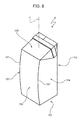
Figure 8 is a perspective view of a sealed package folded by a folding unit which is arranged downstream from the packaging unit ofFigures 1 and6 ; -
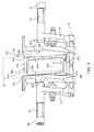
Figure 9 is a section along line VI-VI of a packaging unit according to the present invention, with parts removed for clarity; and -
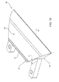
Figure 10 is an enlarged perspective view of a component of the unit ofFigure 9 . - With reference to
Figures 1 ,6 and7 , number 1 indicates as a whole a packaging unit for producing sealedpacks 3 of a pourable food product, such as pasteurized milk or fruit juice, from atube 2 of sheet packaging material. - The packaging material has a multilayer structure (not shown), and comprises a layer of fibrous material, normally paper, covered on both sides with respective layers of heat-seal plastic material, e.g. polyethylene.
- In the case of aseptic packages for long-storage products, such as UHT milk, the packaging material also comprises a layer of gas- and light-barrier material, e.g. aluminium foil or ethylene vinyl alcohol (EVOH) film, which is superimposed on a layer of heat-seal plastic material, and is in turn covered with another layer of heat-seal plastic material forming the inner face of the package eventually contacting the food product.
-
Tube 2 is formed in known manner by longitudinally folding and sealing a web (not shown) of heat-seal sheet material, is filled by a pipe (not shown) with the sterilized or sterile-processed food product for packaging, and is fed, in known manner not shown, along a vertical path having an axis A. - Unit 1 interacts with
tube 2 to heat seal it at equally spaced cross sections and form a number of pillow packs 3 (Figure 1 ) connected totube 2 by sealing bands crosswise to axis A. -
Packs 3 are then conveyed and folded intocorresponding packages 4 in a folding unit (not shown) which is arranged downstream from unit 1. - With reference to
Figure 8 ,package 4 is of the type disclosed in the European Patent Application no.10165116 - Very briefly,
package 4 extends along an axis F and comprises: - a slanted
top wall 100 inclined relative to axis F; - a
bottom wall 101 orthogonal to axis F; - a convex front and a flat
rear wall walls - a pair of concave
lateral walls walls walls - Furthermore, convex
front wall 102 is laterally bounded by to curvedcrease lines 107 which are opposite to each other and extend betweenwalls - Unit 1 comprises at least two forming assemblies 6 (only one of which is shown in detail in
Figures 1 ,6 and7 ), which move vertically along respective verticalcylindrical guides 5 symmetrical with respect to axis A, and interact cyclically withtube 2 to grip and heat seal it along equally spaced cross sections crosswise to axis A. - More specifically, assemblies 6 move upwards along
guides 5 from a bottom dead-centre position to a top dead-centre position, and vice versa downwards. -
Assemblies 6 being known and identical, only one is described below, and identical or corresponding parts ofassemblies 6 are indicated in the attached drawings using the same reference numbers. - More specifically,
assembly 6 substantially comprises a slide 7 that slides alongrespective guide 5; and twojaws -
Jaws tube 2, and are movable, about respective axes F, between a closed configuration in which they grip tube 2 (Figure 1 ), and an open configuration, in which they are detached from tube 2 (Figure 2 ). - More specifically, each
jaw base portion 10 hinged at its bottom end to a bottom portion of slide 7 about respective axis F; and anarm 11, which interacts withtube 2, is connected toportion 10, and extends perpendicularly to axis A whenjaws tube 2. -
Jaws guide 5, and open and close with respect totube 2 of packaging material by rotating about respective axes F about which they are hinged to slide 7; and the open-close movement is superimposed on the up-down vertical movement of slide 7. - The vertical and open-close movements are controlled respectively by known first and second actuating devices, not shown by not being essential to a clear understanding of the present invention.
- Very briefly, the actuating devices provide for
rotating jaws - The movements of the two
assemblies 6 are offset by a half-period: afirst assembly 6 travels upwards with relative jaws open while asecond assembly 6 travels downwards, so thatarms 11 of thefirst assembly 6 pass between corresponding arms of thesecond assembly 6 with no interference. - With reference to
Figure 6 ,assembly 6 also comprises a known sealing device, not shown in the drawings, to heat seal each cross section of thetube 2 of packaging material gripped betweenrelative jaws - The sealing device comprises a heating member fitted to
arm 11 ofjaw 8b, and which interacts withtube 2 by means of two active surfaces; and two pressure pads fitted toarm 11 ofjaw 8a, and which cooperate with respective active surfaces of the heating member to grip and heat seal tube 2 (Figure 6 ). -
Jaw 8b also comprises a cuttingmember 150 and afront seat 151 which normally houses cuttingmember 150. - In detail, cutting
member 150 is normally maintained in a withdrawn rest position in which it is housed completely insideseat 151 by ahelical spring 152. Cuttingmember 150 is moved by a not-shown actuator into a forward cutting position, in which it projects frontwards fromjaw 8b, engages agroove 153 defined byarm 11 ofjaw 8a, and cuts thetube 2. -
Assembly 6 also comprises (Figures 2 ,5 and6 ): - two forming
members respective jaws - a pair of folding flaps 70 (only one of which is shown in
Figure 6 ) which are hinged toarm 11 ofjaw 8b about relative axes D. - With reference to
Figure 6 ,jaw 8a comprises awedge 90 which is bounded by awall 91 parallel to axis A, awall 92 orthogonal to wall 91 and axis A, and awall 93 slanted relative towalls -
Wedge 90 is fixed tojaw 8a. -
Walls - In other words,
walls -
Wall 91 ofwedge 90 rests abovearm 11 ofjaw 8a andwall 93 is arranged relative to wall 91 on the side of formingmembers -
Wall 93 extends between anedge 94 in common withwall 91 and anedge 95, opposite to edge 94, in common withwall 92. - Folding flaps 70 are arranged on either side of
tube 2 and comprise each, in the embodiment shown, a substantially triangular main portion. - Main portion of each
folding flap 70 comprises an apex 71 on the opposite side of axis D and twolateral sides 72 diverging from apex towards axis D - The surfaces of folding flaps 70 adapted to cooperate with
tube 2 are advantageously convex. - In detail, flaps 70 is adapted to form a bottom end 200 (
Figure 1 ) and at least part oflateral walls 204 ofpack 3 which are intended to form respectivelywall 100 andwalls 104 ofpackage 4. -
Wall 93 ofwedge 90 cooperates withflap 70 to form bottom end 200 (Figure 1 ) ofpack 3, which is intended to be folded intowall 100 ofpackage 4. - Each forming
member Figures 3 ,4 and5 ): - a respective half-
shell main wall sidewalls wall - two
levers 51 extending alongsiderelative sidewalls corresponding wall relative jaw - a
crosspiece 53 having, in turn, respective end portions connected to relatelevers 51 and an intermediate portion, which facerelative wall - a pair of
arms 54 which protrude, integrally tolevers 51, fromrespective sidewalls cam follower rollers 55. - Due to the fact that forming
members relative jaws shells Figure 2 ), into which they are pushed by a coil spring 19 (Figure 6 ), and a closed position (Figure 1 ), in which they mate to define a space defining the shape and the volume ofpacks 3 being formed between half-shells - Half-
shells rollers 55 with a not-shown fixed cam extending parallel to axis A. - More specifically, as
assembly 6 moves downwards andjaws shells - a closing stroke, in which half-
shells tube 2 from the open to the closed position; - a volume-control stroke, in which half-
shells Figures 1 and7 ); and - an opening stroke produced by springs 19 (
Figure 6 ), and in which half-shells tube 2 from the closed to the open position. - As
assembly 6 moves upwards andjaws shells tube 2 by spring 19 (Figure 2 ). - With reference to
figures 3 to 5 ,main wall shell surface sidewalls relative surfaces relative surfaces - In detail, each
surface 80a (80b) ofwall 25a (25b) is bounded by: - top and
bottom end edges -
end edges edges - Each
surface 81a (81b) ofsidewalls 26a (26b) is bounded by: -
end edge 28a (28b) on the opposite side to axis A; - an
end edge 29a (29b) which is arranged on the side of axis A; and - a pair of top and
bottom edges 30a (30b) arranged betweenend edge 28a (28b) andend edge 29a (29b). -
Edges 30a (30b) are opposite to each other and extend one between bottom points ofedges edges - When half-
shells surfaces walls first portions Figure 7 ) oftube 2 extending between two consecutive sealing sections and located on opposite sides of axis A. - Furthermore, surfaces 81a, 81b of
sidewalls relative portions tube 2, extending between said two sealing sections oftube 2, to control the volume of thepack 3 being formed between the two consecutive sealing sections. -
Edges top edges - relative
first portions 84a, 84b which extend at increasing distances fromrelative edges -
relative portions relative edges shells Figure 6 ). -
Portions 84a, 84b define, when half-shells Figure 6 ), twotriangular openings 140 arranged on either side oftube 2 and partially engaged relative folding flaps 70. - In detail the width of
openings 140 measured orthogonally to axis A increases proceeding from relative axes C, D towards correspondingtop edges -
Portions tube 2 form respectively the front andrear wall 202, 203 (Figure 1 ) ofpack 3, after the forming thereof has been completed. -
Portions lateral walls 204 ofpack 3, after the forming thereof has been completed. - When
jaws relative arms 11 cooperate along an interaction surface which lies on a plane Q parallel to axis A (Figure 6 ). In which case, the distance between axis C of formingmember 20b from plane Q (and axis A) is greater than the distance between axis D of formingmember 20a form such a plane Q (and axis A). -
Surface 80a is concave. - In greater detail,
surface 80a comprises (Figures 3 ,4 and6 ): - a first
concave area 82a bounded, on opposite sides, byedges closed boundary 31; and - a second
concave area 83a rounded toarea 82a, projecting from theboundary 31 on side of axis A, and gently rounded toarea 82a. - In detail,
edges 27a defines a plane P andwhole surface 80a extends on the side of plane P which is opposite to sidewalls 26a and to axis A. -
Edges 28a extends at first at increasing and then at decreasing distances form plane P, when proceeding fromtop edge 27a towardsbottom edge 27a. - Furthermore, edges 28a converge towards each other and diverge from each other, when proceeding from
top edge 27a towardsbottom edge 27a. - Preferably, edges 28a are curved.
- With reference to
Figure 5 and6 ,surface 80b ofwall 25b comprises: - a main
flat area 86b; and - a
convex shim 87b projecting fromarea 86b towards axis A. -
Surfaces 81b ofsidewalls 26b are flat and define (Figure 5 ) respective angles α witharea 86b. Each angle α is greater than 90 degrees, so thatsurfaces 81b diverge fromsurface 80b towards axis A. - Preferably, each angle α ranges between 90 to 95 degrees, the end-points not included. In particular, angle α ranges between 91 and 92 degrees.
- Finally, the maximum distance D1 (
Figure 4 ) betweenedges 29a ofsidewalls 26a andsurface 82a ofwall 25a is greater than the maximum distance D2 betweenedges 29b ofsidewalls 26b andarea 86b ofwall 25b (Figure 5 ). - Distance D1 is measured orthogonally to plane P and distance D2 is measured orthogonally to
area 86b. - In actual use,
tube 2, filled with the liquid food product is fed along axis A, and first andsecond assemblies 6, operating a half-period out of phase, move upwards and downwards alongrespective guides 5. - More specifically,
first assembly 6 moves upwards, withjaws second assembly 6 moves down, withjaws arm 11 ofsecond assembly 6 pass between, and so avoid interfering with,arms 11 offirst assembly 6. - Operation of unit 1 is described below with reference to
first assembly 6 only, and as of the top dead-centre position, in whichjaws - As of the top dead-centre position,
jaws - At the same time, half-
shells shells tube 2 form the open to the closed position under the action of not-shown cam. - Once that half-
shells tube 2, the sealing device is activated, and half-shells pack 3 being formed astube 2 is transversally heat-sealed. - In greater detail, surfaces 80a, 80b of
walls first portions Figure 7 ) oftube 2 extending between two consecutive sealing sections and located on opposite sides of axis A, and surfaces 81a, 81b ofsidewalls relative portions tube 2, extending between said two sealing sections oftube 2. - Furthermore,
sidewalls tube 2,openings 140 which are engaged byrelative flaps 70 andwedge 90. - Due to the fact that
surface 80a and interacting surfaces offlaps 70 are concave, and surfaces 81a are convex,front wall 202 of pack 3 - corresponding substantially toportion 35a - is formed as convex andlateral walls 204 ofpack 3 are formed at least in part as concave. - Furthermore, flaps 70 and
wall 93 ofwedge 90 are adapted to formbottom end 200 and at least part oflateral walls 204 ofpack 3 which are intended to form respectivelywall 100 andwalls 104 ofpackage 4. - Once that sealing has been completed, cutting
member 150 is actuated and moved to the forward cutting position, so as to cuttube 2 along the previously formed transversal sealing and to separate the formedpack 3 from the remaining part oftube 2. - At this stage, half-
shells tube 2 under the action ofsprings 19 until they reach the open position. - As
assembly 6 reaches the bottom dead centre position,jaws -
Assembly 6 then travels upwards, while assembly 6' travels downwards with relative jaws in the closed configuration. - The formed packs 3 are conveyed to the folding unit which is arranged downstream from unit 1 so as to form
relative packages 4. - Number 1' in
Figure 9 indicates as a whole a packaging unit in accordance with the present invention. - Unit 1' is similar to unit 1, and is only described below as regards the differences between the two; any corresponding or equivalent parts of unit 1, 1' being indicated, where possible, using the same reference numbers.
- In particular, unit 1' differs from unit 1 in that edges 94, 95 of wedge 90' are joined by a plane R and in that wall 93' of wedge 90' wholly extends on the side of plane R opposite to
jaw 8a. - In other words, wall 93' bulges towards forming
members Figures 9 and10 ). - More precisely, wall 93' is convex and curved.
- The operation of unit 1' differs from the one of unit 1 in that wall 93', due to its curved conformation, expels a certain amount of food product away from
pack 3 which is being formed upwards and inside the portion oftube 2 arrange abovepack 3. - In this way,
pack 3 may be formed with a geometrical volume that is greater than the nominal volume of food product that packs 3 contains. - The advantages of unit 1' according to the present invention will be clear from the foregoing description.
- In particular, unit 1' can form packs 3' having a geometrical volume that is greater than the nominal volume of food product it contains, by using bulging walls 93' of
wedge 90 for expelling an additional amount of pourable product from the volume intended to formpack 3 towards the remaining part oftube 2. - In this way, the final volume of
pack 3 may be controlled without increasing the extent to whicharea 83a projects fromarea 82a and/or the thickness ofshim 87b. - Furthermore, the final volume of
pack 3 may be controlled without requiring the injection of a gas insidetube 2. - Clearly, changes may be made to unit 1' as described and illustrated herein without, however, departing from the scope defined in the accompanying Claims.
- In particular, forming
member 20b could be fitted tojaw 8a and formingmember 20a could be fitted tojaw 8b. - Furthermore,
jaw tube 2 opposite to one another. - Wedge 90' could be fitted to
jaw 8b. - Unit 1' could be used for forming
packages 4 having aflat wall 102. - In this case,
jaws member 20a having aflat surface 80a.
Claims (3)
- A packaging unit (1') for producing sealed packs (3) of pourable food products intended to be folded into corresponding packages (4); said packages (4) having an end axial slanted wall (100) relative to a longitudinal axis (F) of said package (4);
said packaging unit (1') comprising a first and a second jaw (8a, 8b) movable cyclically between a closed configuration, in which they grip and seal said tube (2) and an open configuration, in which they are detached from said tube (2);
said first and second jaws (8a, 8b) having respective forming members (20a, 20b) for controlling the volume of said packs (3), when said first and second jaws (8a, 8b) are in said closed configuration;
one (8a) of said first and second jaws (8a, 8b) comprising a wedge (90');
said wedge (90') comprising, in turn, a wall (93') which is adapted to cooperate with and to form an axial end (200) of said pack (3) intended to be folded into said slanted wall (100),
characterized in that said wall (93') has a first and a second end edges (94', 95') joined by a first plane (R);
said wall (93') extending on the opposite side of said first plane (R) relative to said one (8a) of said first and second jaws (8a, 8b). - The packaging unit of claim 1, characterized in that said wall (93') is convex.
- The packaging unit of claim 1 or 2, characterized by comprising:- at least one folding flap (70) which is adapted to fold said axial end (200) and to form at least a part of lateral walls (204) of said pack (3);
said forming members (20a, 20b) defining, when they are in said closed configuration in which they cooperate with said tube (2), at least one opening (140) engaged by said folding flap (70);
said wedge (90') engaging a part of said opening (140).
Priority Applications (1)
| Application Number | Priority Date | Filing Date | Title |
|---|---|---|---|
| EP13195210.3A EP2712816B1 (en) | 2010-12-21 | 2011-12-16 | Packaging unit for producing sealed packs of pourable food products and intended to be folded into corresponding packages |
Applications Claiming Priority (3)
| Application Number | Priority Date | Filing Date | Title |
|---|---|---|---|
| EP10196340A EP2468634A1 (en) | 2010-12-21 | 2010-12-21 | Forming member for forming sealed packages of pourable food products from a tube of packaging material |
| EP13195210.3A EP2712816B1 (en) | 2010-12-21 | 2011-12-16 | Packaging unit for producing sealed packs of pourable food products and intended to be folded into corresponding packages |
| EP11810665.7A EP2655195B1 (en) | 2010-12-21 | 2011-12-16 | Forming member for forming sealed packages of pourable food products from a tube of packaging material |
Related Parent Applications (2)
| Application Number | Title | Priority Date | Filing Date |
|---|---|---|---|
| EP11810665.7A Division EP2655195B1 (en) | 2010-12-21 | 2011-12-16 | Forming member for forming sealed packages of pourable food products from a tube of packaging material |
| EP11810665.7A Division-Into EP2655195B1 (en) | 2010-12-21 | 2011-12-16 | Forming member for forming sealed packages of pourable food products from a tube of packaging material |
Publications (2)
| Publication Number | Publication Date |
|---|---|
| EP2712816A1 true EP2712816A1 (en) | 2014-04-02 |
| EP2712816B1 EP2712816B1 (en) | 2015-05-27 |
Family
ID=43875231
Family Applications (3)
| Application Number | Title | Priority Date | Filing Date |
|---|---|---|---|
| EP10196340A Withdrawn EP2468634A1 (en) | 2010-12-21 | 2010-12-21 | Forming member for forming sealed packages of pourable food products from a tube of packaging material |
| EP11810665.7A Active EP2655195B1 (en) | 2010-12-21 | 2011-12-16 | Forming member for forming sealed packages of pourable food products from a tube of packaging material |
| EP13195210.3A Active EP2712816B1 (en) | 2010-12-21 | 2011-12-16 | Packaging unit for producing sealed packs of pourable food products and intended to be folded into corresponding packages |
Family Applications Before (2)
| Application Number | Title | Priority Date | Filing Date |
|---|---|---|---|
| EP10196340A Withdrawn EP2468634A1 (en) | 2010-12-21 | 2010-12-21 | Forming member for forming sealed packages of pourable food products from a tube of packaging material |
| EP11810665.7A Active EP2655195B1 (en) | 2010-12-21 | 2011-12-16 | Forming member for forming sealed packages of pourable food products from a tube of packaging material |
Country Status (10)
| Country | Link |
|---|---|
| US (1) | US9387943B2 (en) |
| EP (3) | EP2468634A1 (en) |
| JP (1) | JP6030569B2 (en) |
| KR (1) | KR20130141641A (en) |
| CN (1) | CN103261031B (en) |
| BR (1) | BR112013011579A2 (en) |
| CA (1) | CA2816659A1 (en) |
| MX (1) | MX342730B (en) |
| RU (1) | RU2577898C2 (en) |
| WO (1) | WO2012085804A2 (en) |
Cited By (1)
| Publication number | Priority date | Publication date | Assignee | Title |
|---|---|---|---|---|
| IT202300008166A1 (en) * | 2023-04-26 | 2024-10-26 | Tetra Laval Holdings & Finance | APPARATUS FOR FORMING PACKAGES FOR A PACKAGING MACHINE, PACKAGING MACHINE FOR FORMING PACKAGES FILLED WITH A POURABLE PRODUCT AND METHOD FOR FORMING PACKAGES |
Families Citing this family (17)
| Publication number | Priority date | Publication date | Assignee | Title |
|---|---|---|---|---|
| EP2586718B1 (en) * | 2011-10-31 | 2014-05-28 | Tetra Laval Holdings & Finance S.A. | Folding unit for producing folded packages of pourable food products from relative sealed packs |
| EP2662291B1 (en) * | 2012-05-11 | 2014-10-15 | Tetra Laval Holdings & Finance S.A. | Packaging unit and method for producing sealed packages |
| CN104909008B (en) * | 2014-03-10 | 2019-04-30 | 纷美包装(山东)有限公司 | Filling machine forming member and forming method for continuous production of packaging with packaging material tube |
| EP3145819B1 (en) * | 2014-05-19 | 2020-12-02 | Primapak, LLC | Apparatus and method for making a flexible package |
| JP6916163B2 (en) * | 2015-07-10 | 2021-08-11 | テトラ ラバル ホールディングス アンド ファイナンス エス エイ | Assembly and method for processing packaged containers |
| EP3219629B1 (en) | 2016-03-17 | 2018-11-07 | Tetra Laval Holdings & Finance S.A. | A method and a machine for producing a sealed package |
| EP3219630B1 (en) * | 2016-03-17 | 2018-09-26 | Tetra Laval Holdings & Finance SA | A method of operating a packaging machine for producing sealed packages |
| EP3241770B1 (en) * | 2016-05-06 | 2019-02-27 | Tetra Laval Holdings & Finance S.A. | A packaging unit for producing sealed packages containing a pourable food product from a tube of packaging material |
| ITUA20164637A1 (en) * | 2016-06-24 | 2017-12-24 | Gd Spa | Training station for the production of containers for pourable food products. |
| ITUA20164640A1 (en) * | 2016-06-24 | 2017-12-24 | Gd Spa | Training station and machine for the production of containers for pourable food products. |
| EP3321192A1 (en) * | 2016-11-11 | 2018-05-16 | Tetra Laval Holdings & Finance S.A. | Forming member for controlling the volume of packs of pourable food products formed from a tube of packaging material |
| EP3351478A1 (en) * | 2017-01-23 | 2018-07-25 | Tetra Laval Holdings & Finance S.A. | Forming member for controlling the volume of packs of pourable food products formed from a tube of packaging material |
| CN107336879A (en) * | 2017-08-02 | 2017-11-10 | 纷美(北京)贸易有限公司 | A kind of liquid packaging capacity control device and a kind of bottle placer |
| WO2021001144A1 (en) * | 2019-07-01 | 2021-01-07 | Tetra Laval Holdings & Finance S.A. | A packaging assembly for forming and sealing a plurality of packs containing a pourable product and a method for forming and sealing a plurality of packs |
| JP2025519011A (en) * | 2022-06-10 | 2025-06-24 | テトラ ラバル ホールディングス アンド ファイナンス エス エイ | Forming apparatus for forming and sealing a plurality of packages containing pourable products and packaging assembly - Patents.com |
| US11870695B1 (en) * | 2022-12-16 | 2024-01-09 | Microsoft Technology Licensing, Llc | Virtual machine migration on hypervisor network |
| IT202300001578A1 (en) * | 2023-02-01 | 2024-08-01 | Tetra Laval Holdings & Finance | APPARATUS FOR FORMING PACKAGES FOR A PACKAGING MACHINE AND PACKAGING MACHINE FOR FORMING PACKAGES FILLED WITH A POURABLE PRODUCT |
Citations (2)
| Publication number | Priority date | Publication date | Assignee | Title |
|---|---|---|---|---|
| WO2007114752A1 (en) | 2006-03-31 | 2007-10-11 | Tetra Laval Holdings & Finance S.A. | Forming device, machine, packaging laminate web, forming method and process in producing packages |
| EP2151390A1 (en) * | 2008-08-09 | 2010-02-10 | Tetra Laval Holdings & Finance SA | Packaging method and unit for producing sealed packages of a food product pourable into a tube of packaging material |
Family Cites Families (12)
| Publication number | Priority date | Publication date | Assignee | Title |
|---|---|---|---|---|
| SE454167B (en) * | 1982-09-27 | 1988-04-11 | Tetra Pak Ab | SET AND DEVICE FOR MANUFACTURING PACKAGING CONTAINERS |
| IT1199785B (en) * | 1986-12-16 | 1988-12-30 | Tetra Dev Co | A METHOD AND A DEVICE FOR A FILLING VALVE IN A PACKAGING MACHINE |
| DE4214530A1 (en) * | 1992-04-04 | 1993-10-07 | Kraemer & Grebe Kg | Method and device for producing a reclosable packaging |
| CA2079043A1 (en) | 1992-04-04 | 1993-10-05 | Alfred Schmeck | Method and apparatus for the manufacture of a resealable package |
| JP3827777B2 (en) | 1996-09-17 | 2006-09-27 | 四国化工機株式会社 | Packaging container molding flap |
| DE69724598T2 (en) * | 1997-06-27 | 2004-08-05 | Tetra Laval Holdings & Finance S.A. | Packaging machine for the continuous production of sealed packaging of flowable foods from tubular packaging material |
| SE521162C2 (en) * | 2000-04-20 | 2003-10-07 | Tetra Laval Holdings & Finance | A packaging machine and a method related thereto |
| US6430899B1 (en) * | 2000-06-09 | 2002-08-13 | Tetra Laval Holdings & Finance, Sa | Top sealing and creasing apparatus and method for a gable top carton |
| US6357203B1 (en) * | 2000-06-30 | 2002-03-19 | Tetra Laval Holdings & Finance, Sa | Top pre-folding apparatus for an extended top panel gable top carton |
| ITTO20020470A1 (en) * | 2002-05-31 | 2003-12-01 | Tetra Laval Holdings E Finance | FORMING JAW FOR CREATING A SUCCESSION OF SEALED PACKS STARTING FROM A TUBE OF PACKAGING MATERIAL I |
| RU2294858C1 (en) | 2005-12-12 | 2007-03-10 | Государственное образовательное учреждение высшего профессионального образования "Елецкий государственный университет им. И.А. Бунина" | Trailer-train support-and-coupler gear |
| ES2357977T3 (en) * | 2007-09-28 | 2011-05-04 | TETRA LAVAL HOLDINGS & FINANCE SA | MEMBER TO FORM SEALED CONTAINERS OF VERTIBLE FOOD PRODUCTS FROM A PACKING MATERIAL PIPE. |
-
2010
- 2010-12-21 EP EP10196340A patent/EP2468634A1/en not_active Withdrawn
-
2011
- 2011-12-16 US US13/883,253 patent/US9387943B2/en active Active
- 2011-12-16 MX MX2013005822A patent/MX342730B/en active IP Right Grant
- 2011-12-16 CN CN201180062052.6A patent/CN103261031B/en active Active
- 2011-12-16 EP EP11810665.7A patent/EP2655195B1/en active Active
- 2011-12-16 WO PCT/IB2011/055751 patent/WO2012085804A2/en not_active Ceased
- 2011-12-16 KR KR1020137018611A patent/KR20130141641A/en not_active Ceased
- 2011-12-16 RU RU2013134148/13A patent/RU2577898C2/en not_active IP Right Cessation
- 2011-12-16 BR BR112013011579A patent/BR112013011579A2/en not_active IP Right Cessation
- 2011-12-16 CA CA2816659A patent/CA2816659A1/en not_active Abandoned
- 2011-12-16 EP EP13195210.3A patent/EP2712816B1/en active Active
- 2011-12-16 JP JP2013545594A patent/JP6030569B2/en active Active
Patent Citations (2)
| Publication number | Priority date | Publication date | Assignee | Title |
|---|---|---|---|---|
| WO2007114752A1 (en) | 2006-03-31 | 2007-10-11 | Tetra Laval Holdings & Finance S.A. | Forming device, machine, packaging laminate web, forming method and process in producing packages |
| EP2151390A1 (en) * | 2008-08-09 | 2010-02-10 | Tetra Laval Holdings & Finance SA | Packaging method and unit for producing sealed packages of a food product pourable into a tube of packaging material |
Cited By (3)
| Publication number | Priority date | Publication date | Assignee | Title |
|---|---|---|---|---|
| IT202300008166A1 (en) * | 2023-04-26 | 2024-10-26 | Tetra Laval Holdings & Finance | APPARATUS FOR FORMING PACKAGES FOR A PACKAGING MACHINE, PACKAGING MACHINE FOR FORMING PACKAGES FILLED WITH A POURABLE PRODUCT AND METHOD FOR FORMING PACKAGES |
| WO2024223413A1 (en) * | 2023-04-26 | 2024-10-31 | Tetra Laval Holdings & Finance S.A. | Package forming apparatus for a packaging machine, packaging machine for forming packages filled with a pourable product and method for forming packages |
| EP4458689A1 (en) * | 2023-04-26 | 2024-11-06 | Tetra Laval Holdings & Finance S.A. | Package forming apparatus for a packaging machine, packaging machine for forming packages filled with a pourable product and method for forming packages |
Also Published As
| Publication number | Publication date |
|---|---|
| US20130227918A1 (en) | 2013-09-05 |
| BR112013011579A2 (en) | 2024-01-09 |
| WO2012085804A3 (en) | 2012-10-26 |
| US9387943B2 (en) | 2016-07-12 |
| EP2468634A1 (en) | 2012-06-27 |
| CN103261031A (en) | 2013-08-21 |
| EP2655195A2 (en) | 2013-10-30 |
| KR20130141641A (en) | 2013-12-26 |
| MX342730B (en) | 2016-10-11 |
| CN103261031B (en) | 2016-03-16 |
| CA2816659A1 (en) | 2012-06-28 |
| EP2712816B1 (en) | 2015-05-27 |
| JP6030569B2 (en) | 2016-11-24 |
| WO2012085804A2 (en) | 2012-06-28 |
| EP2655195B1 (en) | 2017-02-08 |
| RU2013134148A (en) | 2015-01-27 |
| MX2013005822A (en) | 2013-07-12 |
| RU2577898C2 (en) | 2016-03-20 |
| JP2014503435A (en) | 2014-02-13 |
Similar Documents
| Publication | Publication Date | Title |
|---|---|---|
| EP2712816B1 (en) | Packaging unit for producing sealed packs of pourable food products and intended to be folded into corresponding packages | |
| EP3476751B1 (en) | A packaging assembly for forming and sealing a plurality of packs containing a pourable food product | |
| US8850780B2 (en) | Member and method for forming sealed packages of pourable food products from a tube of packaging material | |
| US9284078B2 (en) | Packaging unit and method for producing sealed packages | |
| US20170355477A1 (en) | Forming assembly and method for forming a plurality of sealed packs for pourable food products starting from a tube of packaging material | |
| EP3943400B1 (en) | Package forming unit, packaging apparatus having a package forming unit and method for forming packages | |
| US7104028B2 (en) | Forming jaw for producing a succession of sealed packages from a tube of sheet packaging material | |
| EP1526074B1 (en) | Form-and-seal unit for a machine for packaging pourable food products | |
| EP3321192A1 (en) | Forming member for controlling the volume of packs of pourable food products formed from a tube of packaging material | |
| EP3351478A1 (en) | Forming member for controlling the volume of packs of pourable food products formed from a tube of packaging material | |
| HK1146255A (en) | Member and method for forming sealed packages of pourable food products from a tube of packaging material | |
| HK1081924B (en) | Forming jaw for producing a succession of sealed packages from a tube of sheet packaging material |
Legal Events
| Date | Code | Title | Description |
|---|---|---|---|
| PUAI | Public reference made under article 153(3) epc to a published international application that has entered the european phase |
Free format text: ORIGINAL CODE: 0009012 |
|
| AC | Divisional application: reference to earlier application |
Ref document number: 2655195 Country of ref document: EP Kind code of ref document: P |
|
| AK | Designated contracting states |
Kind code of ref document: A1 Designated state(s): AL AT BE BG CH CY CZ DE DK EE ES FI FR GB GR HR HU IE IS IT LI LT LU LV MC MK MT NL NO PL PT RO RS SE SI SK SM TR |
|
| REG | Reference to a national code |
Ref country code: DE Ref legal event code: R079 Ref document number: 602011016854 Country of ref document: DE Free format text: PREVIOUS MAIN CLASS: B65B0009200000 Ipc: B65B0009207000 |
|
| 17P | Request for examination filed |
Effective date: 20141002 |
|
| RBV | Designated contracting states (corrected) |
Designated state(s): AL AT BE BG CH CY CZ DE DK EE ES FI FR GB GR HR HU IE IS IT LI LT LU LV MC MK MT NL NO PL PT RO RS SE SI SK SM TR |
|
| RIC1 | Information provided on ipc code assigned before grant |
Ipc: B65B 3/02 20060101ALI20141031BHEP Ipc: B65B 9/12 20060101ALI20141031BHEP Ipc: B65B 9/207 20120101AFI20141031BHEP Ipc: B65B 51/30 20060101ALI20141031BHEP |
|
| GRAP | Despatch of communication of intention to grant a patent |
Free format text: ORIGINAL CODE: EPIDOSNIGR1 |
|
| INTG | Intention to grant announced |
Effective date: 20150116 |
|
| GRAS | Grant fee paid |
Free format text: ORIGINAL CODE: EPIDOSNIGR3 |
|
| GRAA | (expected) grant |
Free format text: ORIGINAL CODE: 0009210 |
|
| AC | Divisional application: reference to earlier application |
Ref document number: 2655195 Country of ref document: EP Kind code of ref document: P |
|
| AK | Designated contracting states |
Kind code of ref document: B1 Designated state(s): AL AT BE BG CH CY CZ DE DK EE ES FI FR GB GR HR HU IE IS IT LI LT LU LV MC MK MT NL NO PL PT RO RS SE SI SK SM TR |
|
| REG | Reference to a national code |
Ref country code: GB Ref legal event code: FG4D |
|
| REG | Reference to a national code |
Ref country code: CH Ref legal event code: EP |
|
| REG | Reference to a national code |
Ref country code: AT Ref legal event code: REF Ref document number: 728697 Country of ref document: AT Kind code of ref document: T Effective date: 20150615 |
|
| REG | Reference to a national code |
Ref country code: IE Ref legal event code: FG4D |
|
| REG | Reference to a national code |
Ref country code: DE Ref legal event code: R096 Ref document number: 602011016854 Country of ref document: DE |
|
| REG | Reference to a national code |
Ref country code: AT Ref legal event code: MK05 Ref document number: 728697 Country of ref document: AT Kind code of ref document: T Effective date: 20150527 |
|
| REG | Reference to a national code |
Ref country code: LT Ref legal event code: MG4D |
|
| PG25 | Lapsed in a contracting state [announced via postgrant information from national office to epo] |
Ref country code: FI Free format text: LAPSE BECAUSE OF FAILURE TO SUBMIT A TRANSLATION OF THE DESCRIPTION OR TO PAY THE FEE WITHIN THE PRESCRIBED TIME-LIMIT Effective date: 20150527 Ref country code: PT Free format text: LAPSE BECAUSE OF FAILURE TO SUBMIT A TRANSLATION OF THE DESCRIPTION OR TO PAY THE FEE WITHIN THE PRESCRIBED TIME-LIMIT Effective date: 20150928 Ref country code: NO Free format text: LAPSE BECAUSE OF FAILURE TO SUBMIT A TRANSLATION OF THE DESCRIPTION OR TO PAY THE FEE WITHIN THE PRESCRIBED TIME-LIMIT Effective date: 20150827 Ref country code: ES Free format text: LAPSE BECAUSE OF FAILURE TO SUBMIT A TRANSLATION OF THE DESCRIPTION OR TO PAY THE FEE WITHIN THE PRESCRIBED TIME-LIMIT Effective date: 20150527 Ref country code: HR Free format text: LAPSE BECAUSE OF FAILURE TO SUBMIT A TRANSLATION OF THE DESCRIPTION OR TO PAY THE FEE WITHIN THE PRESCRIBED TIME-LIMIT Effective date: 20150527 Ref country code: LT Free format text: LAPSE BECAUSE OF FAILURE TO SUBMIT A TRANSLATION OF THE DESCRIPTION OR TO PAY THE FEE WITHIN THE PRESCRIBED TIME-LIMIT Effective date: 20150527 |
|
| REG | Reference to a national code |
Ref country code: NL Ref legal event code: MP Effective date: 20150527 |
|
| REG | Reference to a national code |
Ref country code: FR Ref legal event code: PLFP Year of fee payment: 5 |
|
| PG25 | Lapsed in a contracting state [announced via postgrant information from national office to epo] |
Ref country code: IS Free format text: LAPSE BECAUSE OF FAILURE TO SUBMIT A TRANSLATION OF THE DESCRIPTION OR TO PAY THE FEE WITHIN THE PRESCRIBED TIME-LIMIT Effective date: 20150927 Ref country code: LV Free format text: LAPSE BECAUSE OF FAILURE TO SUBMIT A TRANSLATION OF THE DESCRIPTION OR TO PAY THE FEE WITHIN THE PRESCRIBED TIME-LIMIT Effective date: 20150527 Ref country code: AT Free format text: LAPSE BECAUSE OF FAILURE TO SUBMIT A TRANSLATION OF THE DESCRIPTION OR TO PAY THE FEE WITHIN THE PRESCRIBED TIME-LIMIT Effective date: 20150527 Ref country code: RS Free format text: LAPSE BECAUSE OF FAILURE TO SUBMIT A TRANSLATION OF THE DESCRIPTION OR TO PAY THE FEE WITHIN THE PRESCRIBED TIME-LIMIT Effective date: 20150527 Ref country code: BG Free format text: LAPSE BECAUSE OF FAILURE TO SUBMIT A TRANSLATION OF THE DESCRIPTION OR TO PAY THE FEE WITHIN THE PRESCRIBED TIME-LIMIT Effective date: 20150827 Ref country code: GR Free format text: LAPSE BECAUSE OF FAILURE TO SUBMIT A TRANSLATION OF THE DESCRIPTION OR TO PAY THE FEE WITHIN THE PRESCRIBED TIME-LIMIT Effective date: 20150828 |
|
| PG25 | Lapsed in a contracting state [announced via postgrant information from national office to epo] |
Ref country code: DK Free format text: LAPSE BECAUSE OF FAILURE TO SUBMIT A TRANSLATION OF THE DESCRIPTION OR TO PAY THE FEE WITHIN THE PRESCRIBED TIME-LIMIT Effective date: 20150527 Ref country code: EE Free format text: LAPSE BECAUSE OF FAILURE TO SUBMIT A TRANSLATION OF THE DESCRIPTION OR TO PAY THE FEE WITHIN THE PRESCRIBED TIME-LIMIT Effective date: 20150527 |
|
| PG25 | Lapsed in a contracting state [announced via postgrant information from national office to epo] |
Ref country code: RO Free format text: LAPSE BECAUSE OF NON-PAYMENT OF DUE FEES Effective date: 20150527 Ref country code: SK Free format text: LAPSE BECAUSE OF FAILURE TO SUBMIT A TRANSLATION OF THE DESCRIPTION OR TO PAY THE FEE WITHIN THE PRESCRIBED TIME-LIMIT Effective date: 20150527 Ref country code: CZ Free format text: LAPSE BECAUSE OF FAILURE TO SUBMIT A TRANSLATION OF THE DESCRIPTION OR TO PAY THE FEE WITHIN THE PRESCRIBED TIME-LIMIT Effective date: 20150527 Ref country code: PL Free format text: LAPSE BECAUSE OF FAILURE TO SUBMIT A TRANSLATION OF THE DESCRIPTION OR TO PAY THE FEE WITHIN THE PRESCRIBED TIME-LIMIT Effective date: 20150527 |
|
| REG | Reference to a national code |
Ref country code: DE Ref legal event code: R097 Ref document number: 602011016854 Country of ref document: DE |
|
| PLBE | No opposition filed within time limit |
Free format text: ORIGINAL CODE: 0009261 |
|
| STAA | Information on the status of an ep patent application or granted ep patent |
Free format text: STATUS: NO OPPOSITION FILED WITHIN TIME LIMIT |
|
| 26N | No opposition filed |
Effective date: 20160301 |
|
| PG25 | Lapsed in a contracting state [announced via postgrant information from national office to epo] |
Ref country code: SI Free format text: LAPSE BECAUSE OF FAILURE TO SUBMIT A TRANSLATION OF THE DESCRIPTION OR TO PAY THE FEE WITHIN THE PRESCRIBED TIME-LIMIT Effective date: 20150527 Ref country code: BE Free format text: LAPSE BECAUSE OF NON-PAYMENT OF DUE FEES Effective date: 20151231 |
|
| PG25 | Lapsed in a contracting state [announced via postgrant information from national office to epo] |
Ref country code: LU Free format text: LAPSE BECAUSE OF FAILURE TO SUBMIT A TRANSLATION OF THE DESCRIPTION OR TO PAY THE FEE WITHIN THE PRESCRIBED TIME-LIMIT Effective date: 20151216 Ref country code: MC Free format text: LAPSE BECAUSE OF FAILURE TO SUBMIT A TRANSLATION OF THE DESCRIPTION OR TO PAY THE FEE WITHIN THE PRESCRIBED TIME-LIMIT Effective date: 20150527 |
|
| REG | Reference to a national code |
Ref country code: CH Ref legal event code: PL |
|
| GBPC | Gb: european patent ceased through non-payment of renewal fee |
Effective date: 20151216 |
|
| PG25 | Lapsed in a contracting state [announced via postgrant information from national office to epo] |
Ref country code: BE Free format text: LAPSE BECAUSE OF FAILURE TO SUBMIT A TRANSLATION OF THE DESCRIPTION OR TO PAY THE FEE WITHIN THE PRESCRIBED TIME-LIMIT Effective date: 20150527 |
|
| REG | Reference to a national code |
Ref country code: IE Ref legal event code: MM4A |
|
| PG25 | Lapsed in a contracting state [announced via postgrant information from national office to epo] |
Ref country code: CH Free format text: LAPSE BECAUSE OF NON-PAYMENT OF DUE FEES Effective date: 20151231 Ref country code: GB Free format text: LAPSE BECAUSE OF NON-PAYMENT OF DUE FEES Effective date: 20151216 Ref country code: IE Free format text: LAPSE BECAUSE OF NON-PAYMENT OF DUE FEES Effective date: 20151216 Ref country code: LI Free format text: LAPSE BECAUSE OF NON-PAYMENT OF DUE FEES Effective date: 20151231 |
|
| REG | Reference to a national code |
Ref country code: FR Ref legal event code: PLFP Year of fee payment: 6 |
|
| PG25 | Lapsed in a contracting state [announced via postgrant information from national office to epo] |
Ref country code: SM Free format text: LAPSE BECAUSE OF FAILURE TO SUBMIT A TRANSLATION OF THE DESCRIPTION OR TO PAY THE FEE WITHIN THE PRESCRIBED TIME-LIMIT Effective date: 20150527 Ref country code: HU Free format text: LAPSE BECAUSE OF FAILURE TO SUBMIT A TRANSLATION OF THE DESCRIPTION OR TO PAY THE FEE WITHIN THE PRESCRIBED TIME-LIMIT; INVALID AB INITIO Effective date: 20111216 |
|
| PG25 | Lapsed in a contracting state [announced via postgrant information from national office to epo] |
Ref country code: NL Free format text: LAPSE BECAUSE OF FAILURE TO SUBMIT A TRANSLATION OF THE DESCRIPTION OR TO PAY THE FEE WITHIN THE PRESCRIBED TIME-LIMIT Effective date: 20150527 Ref country code: SE Free format text: LAPSE BECAUSE OF FAILURE TO SUBMIT A TRANSLATION OF THE DESCRIPTION OR TO PAY THE FEE WITHIN THE PRESCRIBED TIME-LIMIT Effective date: 20150527 Ref country code: CY Free format text: LAPSE BECAUSE OF FAILURE TO SUBMIT A TRANSLATION OF THE DESCRIPTION OR TO PAY THE FEE WITHIN THE PRESCRIBED TIME-LIMIT Effective date: 20150527 |
|
| PG25 | Lapsed in a contracting state [announced via postgrant information from national office to epo] |
Ref country code: MT Free format text: LAPSE BECAUSE OF FAILURE TO SUBMIT A TRANSLATION OF THE DESCRIPTION OR TO PAY THE FEE WITHIN THE PRESCRIBED TIME-LIMIT Effective date: 20150527 |
|
| REG | Reference to a national code |
Ref country code: FR Ref legal event code: PLFP Year of fee payment: 7 |
|
| PG25 | Lapsed in a contracting state [announced via postgrant information from national office to epo] |
Ref country code: MK Free format text: LAPSE BECAUSE OF FAILURE TO SUBMIT A TRANSLATION OF THE DESCRIPTION OR TO PAY THE FEE WITHIN THE PRESCRIBED TIME-LIMIT Effective date: 20150527 |
|
| PG25 | Lapsed in a contracting state [announced via postgrant information from national office to epo] |
Ref country code: AL Free format text: LAPSE BECAUSE OF FAILURE TO SUBMIT A TRANSLATION OF THE DESCRIPTION OR TO PAY THE FEE WITHIN THE PRESCRIBED TIME-LIMIT Effective date: 20150527 Ref country code: TR Free format text: LAPSE BECAUSE OF FAILURE TO SUBMIT A TRANSLATION OF THE DESCRIPTION OR TO PAY THE FEE WITHIN THE PRESCRIBED TIME-LIMIT Effective date: 20150527 |
|
| PGFP | Annual fee paid to national office [announced via postgrant information from national office to epo] |
Ref country code: FR Payment date: 20181120 Year of fee payment: 8 |
|
| PG25 | Lapsed in a contracting state [announced via postgrant information from national office to epo] |
Ref country code: FR Free format text: LAPSE BECAUSE OF NON-PAYMENT OF DUE FEES Effective date: 20191231 |
|
| P01 | Opt-out of the competence of the unified patent court (upc) registered |
Effective date: 20230426 |
|
| PGFP | Annual fee paid to national office [announced via postgrant information from national office to epo] |
Ref country code: IT Payment date: 20251218 Year of fee payment: 15 |
|
| PGFP | Annual fee paid to national office [announced via postgrant information from national office to epo] |
Ref country code: DE Payment date: 20251229 Year of fee payment: 15 |