EP2712209A1 - Method and apparatus for computing metric values for loudspeaker protection - Google Patents
Method and apparatus for computing metric values for loudspeaker protection Download PDFInfo
- Publication number
- EP2712209A1 EP2712209A1 EP12368025.8A EP12368025A EP2712209A1 EP 2712209 A1 EP2712209 A1 EP 2712209A1 EP 12368025 A EP12368025 A EP 12368025A EP 2712209 A1 EP2712209 A1 EP 2712209A1
- Authority
- EP
- European Patent Office
- Prior art keywords
- bpf
- loudspeaker
- voltage
- speaker protection
- current
- Prior art date
- Legal status (The legal status is an assumption and is not a legal conclusion. Google has not performed a legal analysis and makes no representation as to the accuracy of the status listed.)
- Granted
Links
Images


Classifications
-
- H—ELECTRICITY
- H04—ELECTRIC COMMUNICATION TECHNIQUE
- H04R—LOUDSPEAKERS, MICROPHONES, GRAMOPHONE PICK-UPS OR LIKE ACOUSTIC ELECTROMECHANICAL TRANSDUCERS; ELECTRIC HEARING AIDS; PUBLIC ADDRESS SYSTEMS
- H04R9/00—Transducers of moving-coil, moving-strip, or moving-wire type
- H04R9/02—Details
- H04R9/022—Cooling arrangements
-
- H—ELECTRICITY
- H04—ELECTRIC COMMUNICATION TECHNIQUE
- H04R—LOUDSPEAKERS, MICROPHONES, GRAMOPHONE PICK-UPS OR LIKE ACOUSTIC ELECTROMECHANICAL TRANSDUCERS; ELECTRIC HEARING AIDS; PUBLIC ADDRESS SYSTEMS
- H04R29/00—Monitoring arrangements; Testing arrangements
- H04R29/001—Monitoring arrangements; Testing arrangements for loudspeakers
- H04R29/003—Monitoring arrangements; Testing arrangements for loudspeakers of the moving-coil type
-
- H—ELECTRICITY
- H04—ELECTRIC COMMUNICATION TECHNIQUE
- H04R—LOUDSPEAKERS, MICROPHONES, GRAMOPHONE PICK-UPS OR LIKE ACOUSTIC ELECTROMECHANICAL TRANSDUCERS; ELECTRIC HEARING AIDS; PUBLIC ADDRESS SYSTEMS
- H04R3/00—Circuits for transducers
- H04R3/007—Protection circuits for transducers
-
- G—PHYSICS
- G01—MEASURING; TESTING
- G01R—MEASURING ELECTRIC VARIABLES; MEASURING MAGNETIC VARIABLES
- G01R1/00—Details of instruments or arrangements of the types included in groups G01R5/00 - G01R13/00 and G01R31/00
-
- G—PHYSICS
- G01—MEASURING; TESTING
- G01R—MEASURING ELECTRIC VARIABLES; MEASURING MAGNETIC VARIABLES
- G01R19/00—Arrangements for measuring currents or voltages or for indicating presence or sign thereof
-
- G—PHYSICS
- G01—MEASURING; TESTING
- G01R—MEASURING ELECTRIC VARIABLES; MEASURING MAGNETIC VARIABLES
- G01R19/00—Arrangements for measuring currents or voltages or for indicating presence or sign thereof
- G01R19/06—Measuring real component; Measuring reactive component
-
- G—PHYSICS
- G01—MEASURING; TESTING
- G01R—MEASURING ELECTRIC VARIABLES; MEASURING MAGNETIC VARIABLES
- G01R19/00—Arrangements for measuring currents or voltages or for indicating presence or sign thereof
- G01R19/165—Indicating that current or voltage is either above or below a predetermined value or within or outside a predetermined range of values
-
- G—PHYSICS
- G01—MEASURING; TESTING
- G01R—MEASURING ELECTRIC VARIABLES; MEASURING MAGNETIC VARIABLES
- G01R19/00—Arrangements for measuring currents or voltages or for indicating presence or sign thereof
- G01R19/165—Indicating that current or voltage is either above or below a predetermined value or within or outside a predetermined range of values
- G01R19/16528—Indicating that current or voltage is either above or below a predetermined value or within or outside a predetermined range of values using digital techniques or performing arithmetic operations
-
- H—ELECTRICITY
- H03—ELECTRONIC CIRCUITRY
- H03F—AMPLIFIERS
- H03F1/00—Details of amplifiers with only discharge tubes, only semiconductor devices or only unspecified devices as amplifying elements
- H03F1/52—Circuit arrangements for protecting such amplifiers
-
- H—ELECTRICITY
- H04—ELECTRIC COMMUNICATION TECHNIQUE
- H04R—LOUDSPEAKERS, MICROPHONES, GRAMOPHONE PICK-UPS OR LIKE ACOUSTIC ELECTROMECHANICAL TRANSDUCERS; ELECTRIC HEARING AIDS; PUBLIC ADDRESS SYSTEMS
- H04R29/00—Monitoring arrangements; Testing arrangements
- H04R29/001—Monitoring arrangements; Testing arrangements for loudspeakers
Definitions
- loudspeakers can be damaged due to overheating when driven at high output levels, especially for audio applications that contain high frequency components.
- Current practice is to prevent loudspeaker damage by simply hard or soft limiting the maximum power output to the loudspeaker.
- a principal object of the present invention is to prevent over-heating of a loudspeaker.
- a further object of the present invention is to obtain a threshold value that is representative of an actual maximum allowable temperature of a voice coil of a loudspeaker.
- a further object of the present invention is to obtain the threshold value by using auto-correlation and cross-correlation of band-pass filtered current and voltage measurements.
- the method invented comprises the steps of: (4) using cross-correlation and autocorrelations equations based on band-passed measurement results to compute loudspeaker protection metrics including a real part of impedance of a voice coil of the loudspeaker, (5) activating speaker protection device if the real part of the loudspeaker impedance exceeds a threshold, and (6) going back to step (2) if input signals of speaker are active.
- the system invented comprises a speaker protection monitor configured to using cross-correlation and autocorrelations equations based on band-passed measurement results of loudspeaker voltage and loudspeaker current and to compute loudspeaker protection metrics and a speaker protection device lowering, if activated by the speaker protection monitor, a temperature of the voice coil.
- the system comprises said speaker protection monitor comprising: a band-pass filter, an averaging filter, an output port to transmit a signal to a speaker protection device in order to activate the speaker protection device if required, and means to compute cross correlation and autocorrelation calculations comprising computing the loudspeaker threshold.
- said speaker protection device lowering, if activated, a temperature of the voice coil.
- a method and system for obtaining a threshold value for loudspeaker protection, based on instantaneous voltage and current measurements, wherein autocorrelation and cross-correlation of band-pass filtered current and voltage measurements are used to obtain a real part of the complex impedance of the voice coil, are disclosed.
- An important point of the invention is that it does not require a DC or pilot signal to be added to the audio signal in order to perform the measurement, and that it is not disturbed by capacitive or inductive components in the complex impedance of the loudspeaker.
- the metric is related to temperature.
- the real part of the impedance increases with temperature, causing a decrease in power.
- Fig. 1 shows a block diagram of the basic components of the system invented. It depicts a speaker protection device 1 receiving audio input signals V+ and V-.
- a voltage measuring device 5 measures an input voltage of the loudspeaker 9 and a current measuring device 3 measures an input current of the loudspeaker 9.
- the voltage measuring 5 provides a voltage signal 6, representing the voltage measured to a speaker protection monitor 7.
- the current measuring device 3 provides a current signal 4, representing the current measured to a speaker protection monitor 7.
- the speaker protection monitor 7 performs calculations to identify situations requiring actions to protect the loudspeaker 9. In order to monitor such situations speaker protection metric signals 8 are provided to activate the speaker protection device 1. These calculations will be outlined in detail below.
- the speaker protection monitor 7 is a processor.
- the impedance measurement will be inaccurate when the input power is below a certain level. Hence the metric is never positive when the power is below Pmin.
- the Rmin is the minimum real impedance for the metric to become positive, indicating the speaker protection should be activated. For the metric to become positive, R>Rmin and P>Pmin.
- the method invented assumes that instantaneous measurements of the current i m (t) through and voltage v m (t) over the loudspeaker terminals are available.
- the measured signals are generally not equal to the true current and voltage but will have an instantaneous error signals ⁇ i (t) and ⁇ v (t)
- the error signals are caused by noise in the current and voltage sensing devices.
- Threshold ⁇ 1 t ⁇ i bpf ⁇ v bpf ⁇ > est - R min . ⁇ i bpf 2 est
- Threshold1 defined here is the output of the block SUB1 209 shown in Fig. 2 .
- Threshold2 is the output of block SUB2 210 and is defined:
- FIG. 2 shows a flowchart of the steps performed by the speaker protection monitor 7.
- Blocks 200 and 205 are acting as band-pass filters.
- Blocks 204 and 206 are multiplication blocks.
- Block 201 is enabled to square.
- Blocks 202 and 207 are acting as low-pass filters.
- Blocks 203 and 208 are adders.
- Blocks 209 and 210 are enabled to subtract, and block 211 is a comparing block determining, which result of blocks 209 and 210 is smaller.
- Block 200 and 205 the steps according equations (3) and correspondently equation (4) are computed.
- Block 201 calculates equation (5) and block 206 calculates equations (6) and (7).
- Block 202 executes equation (8) and block 207 executes equations (9) and (10).
- Block 203 calculates equation (11) and block 208 calculates equation (12). Equation (13) is calculated by blocks 204 and 209.
- the resonance peak will distort the speaker protection method. For this reason the band pass filters 200 and 201 must be chosen such that the resonance peak is not included in the pass band of the filters.
- Fig. 3b shows simulation results of the square root ( ⁇ vv>/ ⁇ ii>) 32 and of ⁇ iv>/ ⁇ ii> 33 both as function of frequency. Both curves 32 and 33 demonstrate show the very close correlation between the factors sqrt ( ⁇ vv>/ ⁇ ii>) 32 and ⁇ iv>/ ⁇ ii> 33 to the impedance curves shown in Fig. 3a.
Landscapes
- Physics & Mathematics (AREA)
- Engineering & Computer Science (AREA)
- Acoustics & Sound (AREA)
- Signal Processing (AREA)
- Health & Medical Sciences (AREA)
- General Health & Medical Sciences (AREA)
- Otolaryngology (AREA)
- Circuit For Audible Band Transducer (AREA)
Abstract
Description
- This invention relates generally to loudspeaker systems and relates more specifically to methods and apparatus for computing a metric value for loudspeaker protection.
- It is well known that loudspeakers can be damaged due to overheating when driven at high output levels, especially for audio applications that contain high frequency components. Current practice is to prevent loudspeaker damage by simply hard or soft limiting the maximum power output to the loudspeaker.
- As a result the maximum sound pressure level (SPL) that can be produced is severely limited even if the actual temperature of the loudspeaker is below the damage threshold. More advanced systems incorporate a simple thermal model of the loudspeaker which may not be accurate, or a temperature sensor to activate the limiter, which introduces additional complexity and cost.
- Therefore it would be desirable to achieve a method for obtaining a threshold value for loudspeaker protection, based on instantaneous voltage and current measurements.
- It is also challenge for engineers to achieve loudspeaker protection at reasonable cost without requiring additional devices to the loudspeaker.
- A principal object of the present invention is to prevent over-heating of a loudspeaker.
- A further object of the present invention is to obtain a threshold value that is representative of an actual maximum allowable temperature of a voice coil of a loudspeaker.
- A further object of the present invention is to obtain the threshold value by using auto-correlation and cross-correlation of band-pass filtered current and voltage measurements.
- A further object of the invention is to activate a protection circuit if the threshold representative of the maximum temperature of the voice coil is exceeded.
- In accordance with the objects of this invention, a method for computing metrics for loudspeaker protection has been achieved. The method invented comprises, firstly, the following steps: (1) providing a loudspeaker, a voltage and a current meter, a speaker protection monitor comprising computational and filtering means, and a speaker protection device, (2) measuring speaker input current and voltage, and (3) filtering by band-pass filters speaker input voltage and current values measured. Furthermore the method invented comprises the steps of: (4) using cross-correlation and autocorrelations equations based on band-passed measurement results to compute loudspeaker protection metrics including a real part of impedance of a voice coil of the loudspeaker, (5) activating speaker protection device if the real part of the loudspeaker impedance exceeds a threshold, and (6) going back to step (2) if input signals of speaker are active.
- In accordance with the objects of this invention a system for preventing any damage of a loudspeaker because of over-heating of a voice coil has been achieved, The system invented comprises a speaker protection monitor configured to using cross-correlation and autocorrelations equations based on band-passed measurement results of loudspeaker voltage and loudspeaker current and to compute loudspeaker protection metrics and a speaker protection device lowering, if activated by the speaker protection monitor, a temperature of the voice coil.
- In accordance with the objects of this invention a system for preventing any damage of a loudspeaker because of over-heating of a voice coil has been achieved, The system invented comprises, firstly, a loudspeaker comprising at least one voice coil and two signal input ports, a voltage meter measuring a signal input voltage of the loudspeaker and transmitting voltage measurement results to a speaker protection monitor, and a current meter measuring a signal input current of the loudspeaker and transmitting current measurement results to a speaker protection monitor. Furthermore the system comprises said speaker protection monitor comprising: a band-pass filter, an averaging filter, an output port to transmit a signal to a speaker protection device in order to activate the speaker protection device if required, and means to compute cross correlation and autocorrelation calculations comprising computing the loudspeaker threshold. Moreover the system comprises said speaker protection device lowering, if activated, a temperature of the voice coil.
- In the accompanying drawings forming a material part of this description, there is shown:
-
Fig. 1 shows a block diagram of the basic components of the system invented. -
FIG. 2 shows a flowchart of the computational steps performed by the speaker protection monitor. - Fig. 3a shows simulation results of the impedance of loudspeaker as function of frequency.
- Fig. 3b shows simulation results of the square root (<vv>/<ii>) and of <iv>/<ii> both as function of frequency.
-
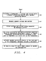
Fig. 4 illustrates a flowchart of key steps of the method for computing metrics for loudspeaker protection invented. - A method and system for obtaining a threshold value for loudspeaker protection, based on instantaneous voltage and current measurements, wherein autocorrelation and cross-correlation of band-pass filtered current and voltage measurements are used to obtain a real part of the complex impedance of the voice coil, are disclosed. An important point of the invention is that it does not require a DC or pilot signal to be added to the audio signal in order to perform the measurement, and that it is not disturbed by capacitive or inductive components in the complex impedance of the loudspeaker.
- The metric is related to temperature. The real part of the impedance increases with temperature, causing a decrease in power.
-
Fig. 1 shows a block diagram of the basic components of the system invented. It depicts a speaker protection device 1 receiving audio input signals V+ and V-. A voltage measuring device 5 measures an input voltage of theloudspeaker 9 and acurrent measuring device 3 measures an input current of theloudspeaker 9. The voltage measuring 5 provides a voltage signal 6, representing the voltage measured to a speaker protection monitor 7. Thecurrent measuring device 3 provides a current signal 4, representing the current measured to a speaker protection monitor 7. - Furthermore the speaker protection monitor 7 performs calculations to identify situations requiring actions to protect the
loudspeaker 9. In order to monitor such situations speakerprotection metric signals 8 are provided to activate the speaker protection device 1. These calculations will be outlined in detail below. The speaker protection monitor 7 is a processor. - The impedance measurement will be inaccurate when the input power is below a certain level. Hence the metric is never positive when the power is below Pmin. The Rmin is the minimum real impedance for the metric to become positive, indicating the speaker protection should be activated. For the metric to become positive, R>Rmin and P>Pmin.
- The method invented assumes that instantaneous measurements of the current im (t) through and voltage vm (t) over the loudspeaker terminals are available. In general the measured signals are generally not equal to the true current and voltage but will have an instantaneous error signals εi(t) and εv(t) The error signals are caused by noise in the current and voltage sensing devices.


- These signals are each passed through a band-pass filter, leading to:


- The band-pass filter can be a combination of a high-pass and low-pass filter, and can be implemented as an analog or digital circuit, for example as an IIR or FIR filter.
- From these values the instantaneous products are obtained:


- These values are passed through an averaging filter, denoted as <>. This may be low-pass filter, such as leaky integrator filter, or digital filter such as a FIR, IIR or sliding average filter. The result after averaging can be expressed as:


- It should be noted that the current noise < εi,bpf 2> should be calibrated in advance. It is a single value, which is equal to the <ibpf2> with an input value of zero.
- If there is no correlation between the actual current and voltage and the measurement noise, the cross terms with the noise, shown in the correspondent equation above, can be neglected. However, the autocorrelations of the noise terms will not vanish:


- If we assume the noise characteristics of the voltage and current measurements are known, then an accurate estimate of the true current and voltage correlations can be obtained as:


An estimate for the real part of the complex impedance can be computed as:
- Due to the power dissipated in the voice coil, its temperature will increase. This will result in a higher resistance. With the proposed method, a threshold value can be set for the maximum resistance (and hence the maximum temperature) that is allowed:

- Threshold1 defined here is the output of the
block SUB1 209 shown inFig. 2 . - Threshold2 is the output of
block SUB2 210 and is defined: - Threshold2 = <ibpfvbpf>est - Pmin
- Rmin is a user configurable value. It is related to the maximum allowed temperature, because R(T) = R0 + alpha*R0*(T-T0), wherein alpha is the resistivity coefficient of the voice coil at reference temperature To, wherein the voice voil has a resistance R0.
- If threshold(t) is positive, the maximum resistance has been exceeded and the protection circuit 1 should be activated.
- The objective of the protection circuit 1 is to lower the temperature of the voice coil, by either reducing the average power that is dissipated as heat, or by improving the cooling of the voice coil. Examples of such protection circuits are:
- A hard or soft limiter, which reduces the maximum voltage on the loudspeaker terminals.
- A gain controller, which attenuates the voltage on the loudspeaker terminals.
- A shelving or low-pass filter, which selectively reduces the amplitude of the high frequency components in the audio signal.
- A shelving or high-pass filter, which selectively reduces the amplitude of the low frequency components in the audio signal.
- An active cooling device, such as a fan or Peltier element, which induces enhanced cooling.
- Alternatively an additional voltage signal may be added to the loudspeaker terminals that induces large displacements of the voice coil. The large displacement will results in elevated air intake and hence enhanced cooling. If the frequency of the additional voltage signal is very low it will be practically inaudible.
-
FIG. 2 shows a flowchart of the steps performed by the speaker protection monitor 7. -
Blocks Blocks Block 201 is enabled to square.Blocks Blocks Blocks blocks - In
block Block 201 calculates equation (5) and block 206 calculates equations (6) and (7).Block 202 executes equation (8) and block 207 executes equations (9) and (10).Block 203 calculates equation (11) and block 208 calculates equation (12). Equation (13) is calculated byblocks - The result of equation (14) is the output of LPF3 shown in
Fig. 2 .
Equation (15) is not calculated, it is equivalent toequation 16, which is the output ofblock SUB1 209. - It should be noted that the preferred embodiment of the disclosure is hard-wired, but alternatively an implementation as a program executed by a processor is also possible.
- Fig. 3a shows simulation results of the impedance of loudspeaker as function of frequency. Curve 30 shows the total impedance and curve 31 illustrates the real part of the impedance. The peak of 1 kHz is caused by a resonance in the loudspeaker.
- The resonance peak will distort the speaker protection method. For this reason the band pass filters 200 and 201 must be chosen such that the resonance peak is not included in the pass band of the filters.
- Fig. 3b shows simulation results of the square root (<vv>/<ii>) 32 and of <iv>/<ii> 33 both as function of frequency. Both curves 32 and 33 demonstrate show the very close correlation between the factors sqrt (<vv>/<ii>) 32 and <iv>/<ii> 33 to the impedance curves shown in Fig. 3a.
-
Fig. 4 illustrates a flowchart of key steps of the method for computing metrics for loudspeaker protection invented.Step 40 illustrates providing a loudspeaker, a voltage and a current meter, a speaker protection monitor and a speaker protection device.Step 41 depicts measuring speaker input current and voltage.Step 42 shows filtering by band-pass filters speaker input voltage and current values measured.Step 43 teaches using cross- correlation and autocorrelations equations based on band-passed measurement results to compute loudspeaker protection metrics.Step 44 illustrates activating speaker protection device if the real part of the loudspeaker impedance exceeds a threshold, and finally step 45 shows going back to step (41) if input signals of speaker are active. - While the invention has been particularly shown and described with reference to the preferred embodiments thereof, it will be understood by those skilled in the art that various changes in form and details may be made without departing from the spirit and scope of the invention.
Claims (25)
- A method for computing metrics for loudspeaker protection, comprising the following steps:(1) providing a loudspeaker, a voltage and a current meter, a speaker protection monitor comprising computational and filtering means, and a speaker protection device;(2) measuring speaker input current and voltage;(3) filtering by band-pass filters speaker input voltage and current values measured;(4) using cross-correlation and autocorrelations equations based on band-passed measurement results to compute loudspeaker protection metrics including a real part of impedance of a voice coil of the loudspeaker;(5) activating speaker protection device if the real part of the loudspeaker impedance exceeds a threshold; and(6) going back to step (2) if input signals of speaker are active.
- The method of claim 1 wherein the band-pass filtered speaker input voltage and current values measured are described by the equations:

and
wherein im,bpf(t) is the filtered input current, ibpf(t) is the input current measured, εi,bpf(t) describe the current error signals, Vm,bpf(t) describes is the filtered input voltage, vbpf(t) is the input voltage measured, and εv,bpf(t) describe the voltage error signals. - The method of claim 2 wherein components of the cross-correlation and autocorrelations equations comprise following equations of instantaneous products required for computations of correlations:


and
- The method of claim 3 wherein said instantaneous products are passed through an averaging filter and the result after averaging can be expressed by following equations:


and
- The method of claim 4 wherein said averaging filter is a low-pass filter, e.g. a leaky integrator filter.
- The method of claim 4 wherein said averaging filter is a digital filter; e.g. a FIR filter, an IIR filter, or a sliding average filter.
- The method of claim 4 wherein said equations can be simplified by the following approximations:

and
- The method of claim 7 wherein accurate estimations of true current and voltage correlations are:

and
- The method of claim 8 wherein based on said estimations of true current and voltage correlations an estimate of the real part of the impedance of the voice coil can be computed following the equation:

wherein Rest is the real part of the impedance of the voice coil- - The method of claim 10 wherein said threshold can be calculated using an equation:

wherein, if threshold(t) is positive, a maximum allowable resistance of the voice coil is exceeded and the speaker protection device is activated. - The method of claim 1 wherein the speaker protection device, if activated, is performing one of the following steps:- lowering a temperature of the voice coil; - improving a cooling of the voice coil; or- lowering the temperature of the voice coil by reducing an average power that is dissipated as heat at the voice coil.
- A system for preventing any damage of a loudspeaker because of over-heating of a voice coil comprising- a speaker protection monitor configured to using cross-correlation and autocorrelations equations based on band-passed measurement results of loudspeaker voltage and loudspeaker current and to compute loudspeaker protection metrics; and- a speaker protection device lowering a temperature of the voice coil, if activated by the speaker protection monitor.
- The system of claim 12 further comprising a voltage meter measuring a signal input voltage of the loudspeaker and transmitting voltage measurement results to a speaker protection monitor and a current meter measuring a signal input current of the loudspeaker and transmitting current measurement results to a speaker protection monitor.
- The system of claim 12 wherein the speaker protection monitor is implemented either on a hard-wired basis, or by a program executed by a processor.
- The system of claim 12 wherein said speaker protection monitor comprises:- a band-pass filter;- an averaging filter;- an output port to transmit a signal to a speaker protection device in order to activate the speaker protection device if required; and- means to compute cross correlation and autocorrelation calculations comprising computing the loudspeaker threshold.
- The system of claim 15 wherein the loudspeaker protection metrics are including a real part of impedance of a voice coil of the loudspeaker.
- The system of claim 16 wherein the activating speaker protection device are activated if the real part of the loudspeaker impedance exceeds a threshold.
- A system for preventing any damage of a loudspeaker because of over-heating of- a voice coil comprising:- a loudspeaker comprising at least one voice coil and two signal input ports;- a voltage meter measuring a signal input voltage of the loudspeaker and transmitting voltage measurement results to a speaker protection monitor;- a current meter measuring a signal input current of the loudspeaker and transmitting current measurement results to a speaker protection monitor;- said speaker protection monitor comprising:one or more band-pass filters;one or more averaging filters;an output port to transmit a signal to a speaker protection device in order to activate the speaker protection device if required; andmeans to compute cross correlation and autocorrelation calculations comprising computing the loudspeaker threshold; andsaid speaker protection device lowering, if activated, a temperature of the voice coil.
- The system of claim 18 wherein each of said one or more band-pass filters is a combination of a high-pass filter and of a low-pass filter, or implemented as digital filter.
- The system of claim 18 wherein the band pass filters are chosen such that a resonance peak of the loudspeaker is not included in a pass band of the band pass filter.
- The system of claim 18 wherein said one or more averaging filters are low-pass filter, digital filters or leaky integrator filters.
- The system of claim 18 wherein said speaker protection device is a hard or soft limiter, which reduces the maximum voltage on the loudspeaker terminals.
- The system of claim 18 wherein said speaker protection device is one of the following elements:- a gain controller, which attenuates the voltage on the loudspeaker terminals;
a shelving or low-pass filter, which selectively reduces the amplitude of the high frequency components in the audio signal; or- a shelving or high-pass filter, which selectively reduces the amplitude of the low frequency components in the audio signal; or - an active cooling device, such as a fan or Peltier element, which induces enhanced cooling. - The system of claim 18 wherein said speaker protection device adds an additional voltage signal to the loudspeaker terminals that induces large displacements of the voice coil.
- The system of claim 18 wherein said means to compute cross correlation and autocorrelation calculations comprise:- blocks processing the current measurement signals comprising- a band-pass filter block;- a block enabled to square;- a low-pass filter block;- a first adder; and- a first multiplying block;- blocks processing the voltage measurement signals comprising:- a band-pass filter block;- a second multiplying block;- a low-pass filter block; and- a second adder;- blocks processing results of said both voltage and current processing blocks comprising:- a first and a second subtracting block; and- a comparing block.
Priority Applications (2)
| Application Number | Priority Date | Filing Date | Title |
|---|---|---|---|
| EP12368025.8A EP2712209B1 (en) | 2012-09-21 | 2012-09-21 | Method and apparatus for computing metric values for loudspeaker protection |
| US13/654,671 US9185493B2 (en) | 2012-09-21 | 2012-10-18 | Method and apparatus for computing metric values for loudspeaker protection |
Applications Claiming Priority (1)
| Application Number | Priority Date | Filing Date | Title |
|---|---|---|---|
| EP12368025.8A EP2712209B1 (en) | 2012-09-21 | 2012-09-21 | Method and apparatus for computing metric values for loudspeaker protection |
Publications (2)
| Publication Number | Publication Date |
|---|---|
| EP2712209A1 true EP2712209A1 (en) | 2014-03-26 |
| EP2712209B1 EP2712209B1 (en) | 2021-01-13 |
Family
ID=47044931
Family Applications (1)
| Application Number | Title | Priority Date | Filing Date |
|---|---|---|---|
| EP12368025.8A Active EP2712209B1 (en) | 2012-09-21 | 2012-09-21 | Method and apparatus for computing metric values for loudspeaker protection |
Country Status (2)
| Country | Link |
|---|---|
| US (1) | US9185493B2 (en) |
| EP (1) | EP2712209B1 (en) |
Cited By (12)
| Publication number | Priority date | Publication date | Assignee | Title |
|---|---|---|---|---|
| EP3035704A1 (en) * | 2014-12-19 | 2016-06-22 | STMicroelectronics (Grenoble) SAS | System and method for protecting an audio speaker |
| US9635480B2 (en) | 2013-03-15 | 2017-04-25 | Cirrus Logic, Inc. | Speaker impedance monitoring |
| US20170359652A1 (en) * | 2016-06-10 | 2017-12-14 | Cirrus Logic International Semiconductor Ltd. | Method for limiting amplifier input current to avoid low voltage conditions |
| GB2551621A (en) * | 2016-06-10 | 2017-12-27 | Cirrus Logic Int Semiconductor Ltd | Method for limiting amplifier input current to avoid low voltage conditions |
| WO2018004547A1 (en) * | 2016-06-28 | 2018-01-04 | Cirrus Logic, Inc. | Speaker impedance monitoring |
| US10187025B1 (en) | 2013-06-13 | 2019-01-22 | Cirrus Logic, Inc. | Systems and methods for predictively preventing a brownout condition in a personal audio device |
| US10212514B2 (en) | 2016-06-10 | 2019-02-19 | Cirrus Logic, Inc. | Method for limiting amplifier input current to avoid low voltage conditions |
| KR20190049298A (en) * | 2017-11-01 | 2019-05-09 | 삼성전자주식회사 | An electronic device comprising an speaker |
| WO2020015970A1 (en) * | 2018-07-19 | 2020-01-23 | Arcelik Anonim Sirketi | A sound system with automatic sound enhancement function |
| WO2021045628A1 (en) * | 2019-09-03 | 2021-03-11 | Elliptic Laboratories As | Proximity detection |
| US11057727B2 (en) | 2019-10-18 | 2021-07-06 | Cirrus Logic, Inc. | Dynamic power/current allocation among groups of audio amplifiers and/or haptic drivers |
| GB2631007A (en) * | 2023-06-14 | 2024-12-18 | Cirrus Logic Int Semiconductor Ltd | Dynamic control for selective acoustic optimization of thermally or power limited speaker systems |
Families Citing this family (18)
| Publication number | Priority date | Publication date | Assignee | Title |
|---|---|---|---|---|
| US9014390B2 (en) * | 2009-10-22 | 2015-04-21 | Dolby Laboratories Licensing Corporation | Digital communication system for loudspeakers |
| US9729986B2 (en) * | 2012-11-07 | 2017-08-08 | Fairchild Semiconductor Corporation | Protection of a speaker using temperature calibration |
| US9247342B2 (en) | 2013-05-14 | 2016-01-26 | James J. Croft, III | Loudspeaker enclosure system with signal processor for enhanced perception of low frequency output |
| GB2522449B (en) * | 2014-01-24 | 2016-07-13 | Cirrus Logic Int Semiconductor Ltd | Loudspeaker protection systems and methods |
| GB2526881B (en) * | 2014-06-06 | 2017-10-04 | Cirrus Logic Int Semiconductor Ltd | Temperature monitoring for loudspeakers |
| US9705559B2 (en) | 2014-11-10 | 2017-07-11 | Dialog Semiconductor (Uk) Limited | Method and apparatus for powering a portable device |
| JP6606936B2 (en) * | 2015-09-14 | 2019-11-20 | 株式会社Jvcケンウッド | Speaker protection device and speaker protection method |
| US9749739B2 (en) * | 2015-09-18 | 2017-08-29 | Qualcomm Incorporated | Protection of a speaker from thermal damage |
| US9807528B1 (en) | 2015-09-21 | 2017-10-31 | Apple Inc. | Electronic devices and method for thermal monitoring of an electro-mechanical actuator |
| US9794687B2 (en) * | 2015-09-28 | 2017-10-17 | Cirrus Logic, Inc. | Loudspeaker protection circuitry and methods |
| US10193361B2 (en) | 2016-05-16 | 2019-01-29 | Motorola Solutions, Inc. | Battery protection circuit and method |
| US10368167B2 (en) * | 2016-11-28 | 2019-07-30 | Motorola Solutions, Inc. | Audio power circuit and method |
| US10461527B2 (en) | 2017-04-20 | 2019-10-29 | Motorola Solutions, Inc. | Battery power limiting circuit and method |
| GB2563460B (en) * | 2017-06-15 | 2021-07-14 | Cirrus Logic Int Semiconductor Ltd | Temperature monitoring for loudspeakers |
| LU100989B1 (en) * | 2018-11-12 | 2020-05-12 | Hochschule Duesseldorf | Method for improving sound reproduction of low frequencies and apparatus therefore |
| JP7454119B2 (en) * | 2019-08-21 | 2024-03-22 | マツダ株式会社 | Vehicle sound generator |
| EP4101180B1 (en) * | 2020-03-13 | 2025-07-02 | Google LLC | Panel loudspeaker temperature monitoring and control |
| US12047757B2 (en) * | 2021-11-09 | 2024-07-23 | Cirrus Logic Inc. | Windowing filter for amplifier device |
Citations (4)
| Publication number | Priority date | Publication date | Assignee | Title |
|---|---|---|---|---|
| GB2187607A (en) * | 1986-03-05 | 1987-09-09 | Malcolm John Hawksford | Apparatus and method for driving loudspeaker systems |
| JPH05264491A (en) * | 1992-03-17 | 1993-10-12 | Hitachi Ltd | Void meter |
| US5343404A (en) * | 1992-11-12 | 1994-08-30 | Maritec Corp. | Precision digital multimeter and waveform synthesizer for multi-signals with distorted waveforms embedded in noise |
| US20090257599A1 (en) * | 2008-04-10 | 2009-10-15 | Bang & Olufsen Icepower A/S | Thermal protection of electro dynamic transducers used in loudspeaker systems |
Family Cites Families (14)
| Publication number | Priority date | Publication date | Assignee | Title |
|---|---|---|---|---|
| US4301330A (en) * | 1979-09-28 | 1981-11-17 | Zenith Radio Corporation | Loudspeaker protection circuit |
| US4583245A (en) * | 1984-06-14 | 1986-04-15 | Renkus-Heinz, Inc. | Speaker system protection circuit |
| US4843562A (en) * | 1987-06-24 | 1989-06-27 | Broadcast Data Systems Limited Partnership | Broadcast information classification system and method |
| JPH0737369Y2 (en) * | 1988-10-17 | 1995-08-23 | ヤマハ株式会社 | Drive device temperature compensation circuit |
| DK168681B1 (en) * | 1992-03-02 | 1994-05-16 | Bang & Olufsen As | Speaker with means for frequency dependent amplitude control |
| DE4336608C2 (en) | 1993-10-27 | 1997-02-06 | Klippel Wolfgang | Circuit arrangement for the protection of electrodynamic loudspeakers against mechanical overload due to high voice coil deflection |
| EP1145593B1 (en) * | 1999-07-02 | 2009-12-02 | Koninklijke Philips Electronics N.V. | Loudspeaker protection system having frequency band selective audio power control |
| US20040086140A1 (en) * | 2002-11-06 | 2004-05-06 | Fedigan Stephen John | Apparatus and method for driving an audio speaker |
| US6940981B2 (en) * | 2003-03-12 | 2005-09-06 | Qsc Audio Products, Inc. | Apparatus and method of limiting power applied to a loudspeaker |
| GB2444307A (en) * | 2006-12-01 | 2008-06-04 | Plextek Ltd | Extracting timing data from a two part preamble, the second part of the preamble being the inverse of the first part. |
| US8582263B2 (en) | 2009-10-20 | 2013-11-12 | Intrinsic Audio Solutions, Inc. | Digitally controlled AC protection and attenuation circuit |
| EP2348750B1 (en) | 2010-01-25 | 2012-09-12 | Nxp B.V. | Control of a loudspeaker output |
| US8194869B2 (en) * | 2010-03-17 | 2012-06-05 | Harman International Industries, Incorporated | Audio power management system |
| EP2541970B1 (en) * | 2011-06-29 | 2014-01-01 | ST-Ericsson SA | Pre-filtering for loudspeakers protection |
-
2012
- 2012-09-21 EP EP12368025.8A patent/EP2712209B1/en active Active
- 2012-10-18 US US13/654,671 patent/US9185493B2/en active Active
Patent Citations (4)
| Publication number | Priority date | Publication date | Assignee | Title |
|---|---|---|---|---|
| GB2187607A (en) * | 1986-03-05 | 1987-09-09 | Malcolm John Hawksford | Apparatus and method for driving loudspeaker systems |
| JPH05264491A (en) * | 1992-03-17 | 1993-10-12 | Hitachi Ltd | Void meter |
| US5343404A (en) * | 1992-11-12 | 1994-08-30 | Maritec Corp. | Precision digital multimeter and waveform synthesizer for multi-signals with distorted waveforms embedded in noise |
| US20090257599A1 (en) * | 2008-04-10 | 2009-10-15 | Bang & Olufsen Icepower A/S | Thermal protection of electro dynamic transducers used in loudspeaker systems |
Cited By (22)
| Publication number | Priority date | Publication date | Assignee | Title |
|---|---|---|---|---|
| US9635480B2 (en) | 2013-03-15 | 2017-04-25 | Cirrus Logic, Inc. | Speaker impedance monitoring |
| US10187025B1 (en) | 2013-06-13 | 2019-01-22 | Cirrus Logic, Inc. | Systems and methods for predictively preventing a brownout condition in a personal audio device |
| US10021482B2 (en) | 2014-12-19 | 2018-07-10 | STMicroelectronics (Alps) SAS | Audio speaker protection system and method |
| FR3030983A1 (en) * | 2014-12-19 | 2016-06-24 | STMicroelectronics (Alps) SAS | |
| US9693138B2 (en) | 2014-12-19 | 2017-06-27 | STMicroelectronics (Alps) SAS | Audio speaker protection system and method |
| EP3035704A1 (en) * | 2014-12-19 | 2016-06-22 | STMicroelectronics (Grenoble) SAS | System and method for protecting an audio speaker |
| US10231050B2 (en) * | 2016-06-10 | 2019-03-12 | Cirrus Logic, Inc. | Method for limiting amplifier input current to avoid low voltage conditions |
| GB2551621A (en) * | 2016-06-10 | 2017-12-27 | Cirrus Logic Int Semiconductor Ltd | Method for limiting amplifier input current to avoid low voltage conditions |
| US10212514B2 (en) | 2016-06-10 | 2019-02-19 | Cirrus Logic, Inc. | Method for limiting amplifier input current to avoid low voltage conditions |
| US20170359652A1 (en) * | 2016-06-10 | 2017-12-14 | Cirrus Logic International Semiconductor Ltd. | Method for limiting amplifier input current to avoid low voltage conditions |
| WO2018004547A1 (en) * | 2016-06-28 | 2018-01-04 | Cirrus Logic, Inc. | Speaker impedance monitoring |
| EP3697106A4 (en) * | 2017-11-01 | 2020-12-16 | Samsung Electronics Co., Ltd. | ELECTRONIC DEVICE WITH SPEAKER |
| KR20190049298A (en) * | 2017-11-01 | 2019-05-09 | 삼성전자주식회사 | An electronic device comprising an speaker |
| US11095988B2 (en) | 2017-11-01 | 2021-08-17 | Samsung Electronics Co., Ltd. | Electronic device comprising speaker |
| WO2020015970A1 (en) * | 2018-07-19 | 2020-01-23 | Arcelik Anonim Sirketi | A sound system with automatic sound enhancement function |
| WO2021045628A1 (en) * | 2019-09-03 | 2021-03-11 | Elliptic Laboratories As | Proximity detection |
| US11997461B2 (en) | 2019-09-03 | 2024-05-28 | Elliptic Laboratories As | Proximity detection |
| US12200452B2 (en) | 2019-09-03 | 2025-01-14 | Elliptic Laboratories As | Proximity detection |
| US11057727B2 (en) | 2019-10-18 | 2021-07-06 | Cirrus Logic, Inc. | Dynamic power/current allocation among groups of audio amplifiers and/or haptic drivers |
| GB2631007A (en) * | 2023-06-14 | 2024-12-18 | Cirrus Logic Int Semiconductor Ltd | Dynamic control for selective acoustic optimization of thermally or power limited speaker systems |
| GB2631007B (en) * | 2023-06-14 | 2025-06-11 | Cirrus Logic Int Semiconductor Ltd | Dynamic control for selective acoustic optimization of thermally or power limited speaker systems |
| US12507015B2 (en) | 2023-06-14 | 2025-12-23 | Cirrus Logic Inc. | Dynamic control for selective acoustic optimization of thermally or power limited speaker systems |
Also Published As
| Publication number | Publication date |
|---|---|
| EP2712209B1 (en) | 2021-01-13 |
| US20140086418A1 (en) | 2014-03-27 |
| US9185493B2 (en) | 2015-11-10 |
Similar Documents
| Publication | Publication Date | Title |
|---|---|---|
| US9185493B2 (en) | Method and apparatus for computing metric values for loudspeaker protection | |
| US9264829B2 (en) | Device and method for detecting force factor of loudspeaker | |
| CN104735600A (en) | Loudspeaker controller | |
| JP2019193786A5 (en) | ||
| EP2591615B1 (en) | System and method for measuring and validating the occlusion effect of a hearing aid user | |
| US20090257599A1 (en) | Thermal protection of electro dynamic transducers used in loudspeaker systems | |
| TW202119824A (en) | Protection of speaker from excess excursion | |
| EP3054707B1 (en) | Device, method, and program for measuring sound field | |
| JP5375435B2 (en) | Seismic intensity measuring device | |
| US20150189427A1 (en) | Device and method for generating driving signal of loudspeaker | |
| CN115372699A (en) | Adaptive filtering method, adaptive filtering device, fault detection method, electronic device, and medium | |
| TWI587711B (en) | Device and method of calculating excursion of diaphragm of loudspeaker and method of controlling loudspeaker | |
| JP2011252761A5 (en) | ||
| CN104248439B (en) | Eardrum acoustic pressure detection method and system | |
| CN106290564B (en) | Grain acoustic attenuation coefficient measuring system and method | |
| CN107870318B (en) | Proximity Detection Method | |
| EP2094030B1 (en) | Method for testing the operating conditions of an electric network and apparatus using said method | |
| CN104483524B (en) | Reactive power metering system in electric energy meter | |
| KR101876358B1 (en) | System for evaluground impedance measurement system | |
| CN111903059A (en) | Method for adaptive digital filtering of impulse noise and filter for implementing the method | |
| CN113115197B (en) | Noise detection method and system | |
| JP5146861B1 (en) | Measuring means and sound effect adjusting means | |
| JP7122225B2 (en) | Processing device, system, processing method, and program | |
| Martel et al. | Identification of time-varying parameters using the derivative formulation of Chebyshev polynomials | |
| JP4572536B2 (en) | Sampling type measuring device |
Legal Events
| Date | Code | Title | Description |
|---|---|---|---|
| PUAI | Public reference made under article 153(3) epc to a published international application that has entered the european phase |
Free format text: ORIGINAL CODE: 0009012 |
|
| AK | Designated contracting states |
Kind code of ref document: A1 Designated state(s): AL AT BE BG CH CY CZ DE DK EE ES FI FR GB GR HR HU IE IS IT LI LT LU LV MC MK MT NL NO PL PT RO RS SE SI SK SM TR |
|
| AX | Request for extension of the european patent |
Extension state: BA ME |
|
| 17P | Request for examination filed |
Effective date: 20140922 |
|
| RBV | Designated contracting states (corrected) |
Designated state(s): AL AT BE BG CH CY CZ DE DK EE ES FI FR GB GR HR HU IE IS IT LI LT LU LV MC MK MT NL NO PL PT RO RS SE SI SK SM TR |
|
| 17Q | First examination report despatched |
Effective date: 20150316 |
|
| STAA | Information on the status of an ep patent application or granted ep patent |
Free format text: STATUS: EXAMINATION IS IN PROGRESS |
|
| RAP1 | Party data changed (applicant data changed or rights of an application transferred) |
Owner name: DIALOG SEMICONDUCTOR BV |
|
| GRAP | Despatch of communication of intention to grant a patent |
Free format text: ORIGINAL CODE: EPIDOSNIGR1 |
|
| STAA | Information on the status of an ep patent application or granted ep patent |
Free format text: STATUS: GRANT OF PATENT IS INTENDED |
|
| INTG | Intention to grant announced |
Effective date: 20200724 |
|
| GRAS | Grant fee paid |
Free format text: ORIGINAL CODE: EPIDOSNIGR3 |
|
| GRAA | (expected) grant |
Free format text: ORIGINAL CODE: 0009210 |
|
| STAA | Information on the status of an ep patent application or granted ep patent |
Free format text: STATUS: THE PATENT HAS BEEN GRANTED |
|
| AK | Designated contracting states |
Kind code of ref document: B1 Designated state(s): AL AT BE BG CH CY CZ DE DK EE ES FI FR GB GR HR HU IE IS IT LI LT LU LV MC MK MT NL NO PL PT RO RS SE SI SK SM TR |
|
| REG | Reference to a national code |
Ref country code: GB Ref legal event code: FG4D |
|
| REG | Reference to a national code |
Ref country code: CH Ref legal event code: EP |
|
| REG | Reference to a national code |
Ref country code: DE Ref legal event code: R096 Ref document number: 602012074132 Country of ref document: DE |
|
| REG | Reference to a national code |
Ref country code: IE Ref legal event code: FG4D |
|
| REG | Reference to a national code |
Ref country code: AT Ref legal event code: REF Ref document number: 1355439 Country of ref document: AT Kind code of ref document: T Effective date: 20210215 |
|
| REG | Reference to a national code |
Ref country code: AT Ref legal event code: MK05 Ref document number: 1355439 Country of ref document: AT Kind code of ref document: T Effective date: 20210113 |
|
| REG | Reference to a national code |
Ref country code: NL Ref legal event code: MP Effective date: 20210113 |
|
| REG | Reference to a national code |
Ref country code: LT Ref legal event code: MG9D |
|
| PG25 | Lapsed in a contracting state [announced via postgrant information from national office to epo] |
Ref country code: HR Free format text: LAPSE BECAUSE OF FAILURE TO SUBMIT A TRANSLATION OF THE DESCRIPTION OR TO PAY THE FEE WITHIN THE PRESCRIBED TIME-LIMIT Effective date: 20210113 Ref country code: FI Free format text: LAPSE BECAUSE OF FAILURE TO SUBMIT A TRANSLATION OF THE DESCRIPTION OR TO PAY THE FEE WITHIN THE PRESCRIBED TIME-LIMIT Effective date: 20210113 Ref country code: GR Free format text: LAPSE BECAUSE OF FAILURE TO SUBMIT A TRANSLATION OF THE DESCRIPTION OR TO PAY THE FEE WITHIN THE PRESCRIBED TIME-LIMIT Effective date: 20210414 Ref country code: PT Free format text: LAPSE BECAUSE OF FAILURE TO SUBMIT A TRANSLATION OF THE DESCRIPTION OR TO PAY THE FEE WITHIN THE PRESCRIBED TIME-LIMIT Effective date: 20210513 Ref country code: LT Free format text: LAPSE BECAUSE OF FAILURE TO SUBMIT A TRANSLATION OF THE DESCRIPTION OR TO PAY THE FEE WITHIN THE PRESCRIBED TIME-LIMIT Effective date: 20210113 Ref country code: BG Free format text: LAPSE BECAUSE OF FAILURE TO SUBMIT A TRANSLATION OF THE DESCRIPTION OR TO PAY THE FEE WITHIN THE PRESCRIBED TIME-LIMIT Effective date: 20210413 Ref country code: NL Free format text: LAPSE BECAUSE OF FAILURE TO SUBMIT A TRANSLATION OF THE DESCRIPTION OR TO PAY THE FEE WITHIN THE PRESCRIBED TIME-LIMIT Effective date: 20210113 Ref country code: NO Free format text: LAPSE BECAUSE OF FAILURE TO SUBMIT A TRANSLATION OF THE DESCRIPTION OR TO PAY THE FEE WITHIN THE PRESCRIBED TIME-LIMIT Effective date: 20210413 |
|
| PG25 | Lapsed in a contracting state [announced via postgrant information from national office to epo] |
Ref country code: SE Free format text: LAPSE BECAUSE OF FAILURE TO SUBMIT A TRANSLATION OF THE DESCRIPTION OR TO PAY THE FEE WITHIN THE PRESCRIBED TIME-LIMIT Effective date: 20210113 Ref country code: AT Free format text: LAPSE BECAUSE OF FAILURE TO SUBMIT A TRANSLATION OF THE DESCRIPTION OR TO PAY THE FEE WITHIN THE PRESCRIBED TIME-LIMIT Effective date: 20210113 Ref country code: LV Free format text: LAPSE BECAUSE OF FAILURE TO SUBMIT A TRANSLATION OF THE DESCRIPTION OR TO PAY THE FEE WITHIN THE PRESCRIBED TIME-LIMIT Effective date: 20210113 Ref country code: RS Free format text: LAPSE BECAUSE OF FAILURE TO SUBMIT A TRANSLATION OF THE DESCRIPTION OR TO PAY THE FEE WITHIN THE PRESCRIBED TIME-LIMIT Effective date: 20210113 Ref country code: PL Free format text: LAPSE BECAUSE OF FAILURE TO SUBMIT A TRANSLATION OF THE DESCRIPTION OR TO PAY THE FEE WITHIN THE PRESCRIBED TIME-LIMIT Effective date: 20210113 |
|
| PG25 | Lapsed in a contracting state [announced via postgrant information from national office to epo] |
Ref country code: IS Free format text: LAPSE BECAUSE OF FAILURE TO SUBMIT A TRANSLATION OF THE DESCRIPTION OR TO PAY THE FEE WITHIN THE PRESCRIBED TIME-LIMIT Effective date: 20210513 |
|
| REG | Reference to a national code |
Ref country code: DE Ref legal event code: R097 Ref document number: 602012074132 Country of ref document: DE |
|
| PG25 | Lapsed in a contracting state [announced via postgrant information from national office to epo] |
Ref country code: SM Free format text: LAPSE BECAUSE OF FAILURE TO SUBMIT A TRANSLATION OF THE DESCRIPTION OR TO PAY THE FEE WITHIN THE PRESCRIBED TIME-LIMIT Effective date: 20210113 Ref country code: CZ Free format text: LAPSE BECAUSE OF FAILURE TO SUBMIT A TRANSLATION OF THE DESCRIPTION OR TO PAY THE FEE WITHIN THE PRESCRIBED TIME-LIMIT Effective date: 20210113 Ref country code: EE Free format text: LAPSE BECAUSE OF FAILURE TO SUBMIT A TRANSLATION OF THE DESCRIPTION OR TO PAY THE FEE WITHIN THE PRESCRIBED TIME-LIMIT Effective date: 20210113 |
|
| PLBE | No opposition filed within time limit |
Free format text: ORIGINAL CODE: 0009261 |
|
| STAA | Information on the status of an ep patent application or granted ep patent |
Free format text: STATUS: NO OPPOSITION FILED WITHIN TIME LIMIT |
|
| PG25 | Lapsed in a contracting state [announced via postgrant information from national office to epo] |
Ref country code: DK Free format text: LAPSE BECAUSE OF FAILURE TO SUBMIT A TRANSLATION OF THE DESCRIPTION OR TO PAY THE FEE WITHIN THE PRESCRIBED TIME-LIMIT Effective date: 20210113 Ref country code: ES Free format text: LAPSE BECAUSE OF FAILURE TO SUBMIT A TRANSLATION OF THE DESCRIPTION OR TO PAY THE FEE WITHIN THE PRESCRIBED TIME-LIMIT Effective date: 20210113 Ref country code: SK Free format text: LAPSE BECAUSE OF FAILURE TO SUBMIT A TRANSLATION OF THE DESCRIPTION OR TO PAY THE FEE WITHIN THE PRESCRIBED TIME-LIMIT Effective date: 20210113 Ref country code: RO Free format text: LAPSE BECAUSE OF FAILURE TO SUBMIT A TRANSLATION OF THE DESCRIPTION OR TO PAY THE FEE WITHIN THE PRESCRIBED TIME-LIMIT Effective date: 20210113 |
|
| 26N | No opposition filed |
Effective date: 20211014 |
|
| PG25 | Lapsed in a contracting state [announced via postgrant information from national office to epo] |
Ref country code: AL Free format text: LAPSE BECAUSE OF FAILURE TO SUBMIT A TRANSLATION OF THE DESCRIPTION OR TO PAY THE FEE WITHIN THE PRESCRIBED TIME-LIMIT Effective date: 20210113 |
|
| PG25 | Lapsed in a contracting state [announced via postgrant information from national office to epo] |
Ref country code: SI Free format text: LAPSE BECAUSE OF FAILURE TO SUBMIT A TRANSLATION OF THE DESCRIPTION OR TO PAY THE FEE WITHIN THE PRESCRIBED TIME-LIMIT Effective date: 20210113 |
|
| PG25 | Lapsed in a contracting state [announced via postgrant information from national office to epo] |
Ref country code: IT Free format text: LAPSE BECAUSE OF FAILURE TO SUBMIT A TRANSLATION OF THE DESCRIPTION OR TO PAY THE FEE WITHIN THE PRESCRIBED TIME-LIMIT Effective date: 20210113 |
|
| REG | Reference to a national code |
Ref country code: CH Ref legal event code: PL |
|
| REG | Reference to a national code |
Ref country code: BE Ref legal event code: MM Effective date: 20210930 |
|
| GBPC | Gb: european patent ceased through non-payment of renewal fee |
Effective date: 20210921 |
|
| PG25 | Lapsed in a contracting state [announced via postgrant information from national office to epo] |
Ref country code: IS Free format text: LAPSE BECAUSE OF FAILURE TO SUBMIT A TRANSLATION OF THE DESCRIPTION OR TO PAY THE FEE WITHIN THE PRESCRIBED TIME-LIMIT Effective date: 20210513 Ref country code: MC Free format text: LAPSE BECAUSE OF FAILURE TO SUBMIT A TRANSLATION OF THE DESCRIPTION OR TO PAY THE FEE WITHIN THE PRESCRIBED TIME-LIMIT Effective date: 20210113 |
|
| PG25 | Lapsed in a contracting state [announced via postgrant information from national office to epo] |
Ref country code: LU Free format text: LAPSE BECAUSE OF NON-PAYMENT OF DUE FEES Effective date: 20210921 Ref country code: IE Free format text: LAPSE BECAUSE OF NON-PAYMENT OF DUE FEES Effective date: 20210921 Ref country code: GB Free format text: LAPSE BECAUSE OF NON-PAYMENT OF DUE FEES Effective date: 20210921 Ref country code: FR Free format text: LAPSE BECAUSE OF NON-PAYMENT OF DUE FEES Effective date: 20210930 Ref country code: BE Free format text: LAPSE BECAUSE OF NON-PAYMENT OF DUE FEES Effective date: 20210930 |
|
| PG25 | Lapsed in a contracting state [announced via postgrant information from national office to epo] |
Ref country code: LI Free format text: LAPSE BECAUSE OF NON-PAYMENT OF DUE FEES Effective date: 20210930 Ref country code: CH Free format text: LAPSE BECAUSE OF NON-PAYMENT OF DUE FEES Effective date: 20210930 |
|
| PG25 | Lapsed in a contracting state [announced via postgrant information from national office to epo] |
Ref country code: HU Free format text: LAPSE BECAUSE OF FAILURE TO SUBMIT A TRANSLATION OF THE DESCRIPTION OR TO PAY THE FEE WITHIN THE PRESCRIBED TIME-LIMIT; INVALID AB INITIO Effective date: 20120921 Ref country code: CY Free format text: LAPSE BECAUSE OF FAILURE TO SUBMIT A TRANSLATION OF THE DESCRIPTION OR TO PAY THE FEE WITHIN THE PRESCRIBED TIME-LIMIT Effective date: 20210113 |
|
| PG25 | Lapsed in a contracting state [announced via postgrant information from national office to epo] |
Ref country code: MK Free format text: LAPSE BECAUSE OF FAILURE TO SUBMIT A TRANSLATION OF THE DESCRIPTION OR TO PAY THE FEE WITHIN THE PRESCRIBED TIME-LIMIT Effective date: 20210113 |
|
| PG25 | Lapsed in a contracting state [announced via postgrant information from national office to epo] |
Ref country code: MT Free format text: LAPSE BECAUSE OF FAILURE TO SUBMIT A TRANSLATION OF THE DESCRIPTION OR TO PAY THE FEE WITHIN THE PRESCRIBED TIME-LIMIT Effective date: 20210113 |
|
| PGFP | Annual fee paid to national office [announced via postgrant information from national office to epo] |
Ref country code: DE Payment date: 20250901 Year of fee payment: 14 |
|
| PG25 | Lapsed in a contracting state [announced via postgrant information from national office to epo] |
Ref country code: TR Free format text: LAPSE BECAUSE OF FAILURE TO SUBMIT A TRANSLATION OF THE DESCRIPTION OR TO PAY THE FEE WITHIN THE PRESCRIBED TIME-LIMIT Effective date: 20210113 |