EP2712048A2 - Ultra-long standby method and ultra-long standby terminal - Google Patents
Ultra-long standby method and ultra-long standby terminal Download PDFInfo
- Publication number
- EP2712048A2 EP2712048A2 EP11777293.9A EP11777293A EP2712048A2 EP 2712048 A2 EP2712048 A2 EP 2712048A2 EP 11777293 A EP11777293 A EP 11777293A EP 2712048 A2 EP2712048 A2 EP 2712048A2
- Authority
- EP
- European Patent Office
- Prior art keywords
- power supply
- terminal
- supply apparatus
- solar power
- solar
- Prior art date
- Legal status (The legal status is an assumption and is not a legal conclusion. Google has not performed a legal analysis and makes no representation as to the accuracy of the status listed.)
- Withdrawn
Links
Images
Classifications
-
- H—ELECTRICITY
- H02—GENERATION; CONVERSION OR DISTRIBUTION OF ELECTRIC POWER
- H02J—ELECTRIC POWER NETWORKS; CIRCUIT ARRANGEMENTS OR SYSTEMS FOR SUPPLYING OR DISTRIBUTING ELECTRIC POWER; SYSTEMS FOR STORING ELECTRIC ENERGY
- H02J9/00—Circuit arrangements for emergency or stand-by power supply, e.g. for emergency lighting
- H02J9/04—Circuit arrangements for emergency or stand-by power supply, e.g. for emergency lighting in which the distribution system is disconnected from the normal source and connected to a standby source
- H02J9/06—Circuit arrangements for emergency or stand-by power supply, e.g. for emergency lighting in which the distribution system is disconnected from the normal source and connected to a standby source with automatic change-over, e.g. UPS systems
- H02J9/061—Circuit arrangements for emergency or stand-by power supply, e.g. for emergency lighting in which the distribution system is disconnected from the normal source and connected to a standby source with automatic change-over, e.g. UPS systems for DC powered loads
-
- H—ELECTRICITY
- H02—GENERATION; CONVERSION OR DISTRIBUTION OF ELECTRIC POWER
- H02J—ELECTRIC POWER NETWORKS; CIRCUIT ARRANGEMENTS OR SYSTEMS FOR SUPPLYING OR DISTRIBUTING ELECTRIC POWER; SYSTEMS FOR STORING ELECTRIC ENERGY
- H02J7/00—Circuit arrangements for charging or discharging batteries or for supplying loads from batteries
- H02J7/34—Parallel operation in networks using both storage and other DC sources, e.g. providing buffering
- H02J7/35—Parallel operation in networks using both storage and other DC sources, e.g. providing buffering with light sensitive cells
-
- H—ELECTRICITY
- H02—GENERATION; CONVERSION OR DISTRIBUTION OF ELECTRIC POWER
- H02J—ELECTRIC POWER NETWORKS; CIRCUIT ARRANGEMENTS OR SYSTEMS FOR SUPPLYING OR DISTRIBUTING ELECTRIC POWER; SYSTEMS FOR STORING ELECTRIC ENERGY
- H02J9/00—Circuit arrangements for emergency or stand-by power supply, e.g. for emergency lighting
- H02J9/005—Circuit arrangements for emergency or stand-by power supply, e.g. for emergency lighting using a power saving mode
-
- H—ELECTRICITY
- H04—ELECTRIC COMMUNICATION TECHNIQUE
- H04W—WIRELESS COMMUNICATION NETWORKS
- H04W52/00—Power management, e.g. Transmission Power Control [TPC] or power classes
- H04W52/02—Power saving arrangements
- H04W52/0209—Power saving arrangements in terminal devices
- H04W52/0261—Power saving arrangements in terminal devices managing power supply demand, e.g. depending on battery level
- H04W52/0296—Power saving arrangements in terminal devices managing power supply demand, e.g. depending on battery level switching to a backup power supply
-
- H—ELECTRICITY
- H10—SEMICONDUCTOR DEVICES; ELECTRIC SOLID-STATE DEVICES NOT OTHERWISE PROVIDED FOR
- H10F—INORGANIC SEMICONDUCTOR DEVICES SENSITIVE TO INFRARED RADIATION, LIGHT, ELECTROMAGNETIC RADIATION OF SHORTER WAVELENGTH OR CORPUSCULAR RADIATION
- H10F77/00—Constructional details of devices covered by this subclass
- H10F77/95—Circuit arrangements
- H10F77/953—Circuit arrangements for devices having potential barriers
- H10F77/955—Circuit arrangements for devices having potential barriers for photovoltaic devices
-
- Y—GENERAL TAGGING OF NEW TECHNOLOGICAL DEVELOPMENTS; GENERAL TAGGING OF CROSS-SECTIONAL TECHNOLOGIES SPANNING OVER SEVERAL SECTIONS OF THE IPC; TECHNICAL SUBJECTS COVERED BY FORMER USPC CROSS-REFERENCE ART COLLECTIONS [XRACs] AND DIGESTS
- Y02—TECHNOLOGIES OR APPLICATIONS FOR MITIGATION OR ADAPTATION AGAINST CLIMATE CHANGE
- Y02B—CLIMATE CHANGE MITIGATION TECHNOLOGIES RELATED TO BUILDINGS, e.g. HOUSING, HOUSE APPLIANCES OR RELATED END-USER APPLICATIONS
- Y02B70/00—Technologies for an efficient end-user side electric power management and consumption
- Y02B70/30—Systems integrating technologies related to power network operation and communication or information technologies for improving the carbon footprint of the management of residential or tertiary loads, i.e. smart grids as climate change mitigation technology in the buildings sector, including also the last stages of power distribution and the control, monitoring or operating management systems at local level
-
- Y—GENERAL TAGGING OF NEW TECHNOLOGICAL DEVELOPMENTS; GENERAL TAGGING OF CROSS-SECTIONAL TECHNOLOGIES SPANNING OVER SEVERAL SECTIONS OF THE IPC; TECHNICAL SUBJECTS COVERED BY FORMER USPC CROSS-REFERENCE ART COLLECTIONS [XRACs] AND DIGESTS
- Y02—TECHNOLOGIES OR APPLICATIONS FOR MITIGATION OR ADAPTATION AGAINST CLIMATE CHANGE
- Y02D—CLIMATE CHANGE MITIGATION TECHNOLOGIES IN INFORMATION AND COMMUNICATION TECHNOLOGIES [ICT], I.E. INFORMATION AND COMMUNICATION TECHNOLOGIES AIMING AT THE REDUCTION OF THEIR OWN ENERGY USE
- Y02D30/00—Reducing energy consumption in communication networks
- Y02D30/70—Reducing energy consumption in communication networks in wireless communication networks
-
- Y—GENERAL TAGGING OF NEW TECHNOLOGICAL DEVELOPMENTS; GENERAL TAGGING OF CROSS-SECTIONAL TECHNOLOGIES SPANNING OVER SEVERAL SECTIONS OF THE IPC; TECHNICAL SUBJECTS COVERED BY FORMER USPC CROSS-REFERENCE ART COLLECTIONS [XRACs] AND DIGESTS
- Y02—TECHNOLOGIES OR APPLICATIONS FOR MITIGATION OR ADAPTATION AGAINST CLIMATE CHANGE
- Y02E—REDUCTION OF GREENHOUSE GAS [GHG] EMISSIONS, RELATED TO ENERGY GENERATION, TRANSMISSION OR DISTRIBUTION
- Y02E10/00—Energy generation through renewable energy sources
- Y02E10/50—Photovoltaic [PV] energy
-
- Y—GENERAL TAGGING OF NEW TECHNOLOGICAL DEVELOPMENTS; GENERAL TAGGING OF CROSS-SECTIONAL TECHNOLOGIES SPANNING OVER SEVERAL SECTIONS OF THE IPC; TECHNICAL SUBJECTS COVERED BY FORMER USPC CROSS-REFERENCE ART COLLECTIONS [XRACs] AND DIGESTS
- Y04—INFORMATION OR COMMUNICATION TECHNOLOGIES HAVING AN IMPACT ON OTHER TECHNOLOGY AREAS
- Y04S—SYSTEMS INTEGRATING TECHNOLOGIES RELATED TO POWER NETWORK OPERATION, COMMUNICATION OR INFORMATION TECHNOLOGIES FOR IMPROVING THE ELECTRICAL POWER GENERATION, TRANSMISSION, DISTRIBUTION, MANAGEMENT OR USAGE, i.e. SMART GRIDS
- Y04S20/00—Management or operation of end-user stationary applications or the last stages of power distribution; Controlling, monitoring or operating thereof
- Y04S20/20—End-user application control systems
Definitions
- the present invention relates to the field of terminal devices, and in particular to, an ultra-long standby method and an ultra-long standby terminal.
- the solar cells that are based on crystalline silicon are dominating the photovoltaic market, and enjoy a market share of more than 90%.
- the solar technology has been widely used in devices such as water heaters, street lamps, and mobile phones.
- the solar conversion rate is only about 15% now in the industry, which becomes a bottleneck for applications in portable terminal products; the normal recharging temperature for a common lithium-ion battery is 0 to 45 degrees Celsius. If a terminal is solar recharged by exposure under the sun, the surface temperature of the terminal rises (under strong sunlight radiation, the surface temperature may reach up to 60 to 70 degrees Celsius), resulting in a large impact on the lithium-ion battery performance. The capacity of the lithium-ion battery attenuates, shortening the standby time of the terminal and affecting user experience.
- the purpose of the present invention is to provide an ultra-long standby method and an ultra-long standby terminal that are able to use solar energy to implement ultra-long standby for a terminal, thereby significantly improving user experience.
- An ultra-long standby method including:
- An ultra-long standby terminal including:
- the mehod disposes a solar power supply apparatus on a terminal and disposesan analog switch between the solar power supply apparatus and a battery within the terminal, where the solar power supply apparatus and the battery form two input paths of an output circuit, the output circuit supplies power to a preset module, and the preset module is a module that matches a power supply voltage and a solar input voltage; detects whether or not the solar power supply apparatus continues to convert electrical energy; and controls, upon detecting that the solar power supply apparatus continues to convert electrical energy, the analog switch to switch the input paths to the solar power supply apparatus so that the solar power supply apparatus supplies power to the preset module, thereby using solar energy to implementing ultra-long standby for a terminal, and significantly improving user experience.
- Embodiments of the present invention provide an ultra-long standby method and an ultra-long standby terminal, where specifically solar energy is used as an auxiliary power supply source in addition to the battery of a terminal, minimizing consumption of the battery in various applications of the terminal, thereby indirectly implementing ultra-long standby for the terminal, and significantly improving user experience.
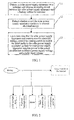
- FIG. 1 is a schematic flowchart of an ultra-long standby method according to an embodiment of the present invention. The method includes:
- Step 11 Dispose a solar power supply apparatus on a terminal and dispose an analog switch between the solar power supply apparatus and a battery within the terminal.
- the solar power supply apparatus may be formed by a solar panel and a photoelectric conversion module, and may be disposed on a rear side of the terminal.
- the solar power supply apparatus may also be disposed in another position of the terminal; the solar panel and photoelectric conversion module may be implemented by common means in the prior art, which is not limited herein.
- the battery and the solar power supply apparatus form two input paths of an output circuit, the output circuit supplies power to a preset module in the terminal, and another output circuit formed by the battery still supplies power to other modules in the terminal.
- the power of the system may be supplied by the input paths of the battery by default; of course, during the specific implementation process, the system may also be set to null by default, and switch to the input path for power supply according to the specific use condition.
- the terminal may include: a mobile phone, tablet computer, or laptop computer, or may also include other terminal devices that use a battery to supply power.
- Step 12 Detect whether or not the solar power supply apparatus continues to convert electrical energy.
- a voltage detection apparatus may be used for detection.
- the voltage detection apparatus detects that the solar power supply apparatus continues to generate voltage, it can be determined that the solar power supply apparatus continues to convert electrical energy.
- Step 13 Upon detecting that the solar power supply apparatus continues to convert electrical energy, control the analog switch to switch the input paths to the solar power supply apparatus so that the solar power supply apparatus supplies power to the preset module that matches a power supply voltage and a solar input voltage.
- the analog switch may be controlled to switch the input paths to the solar power supply apparatus so that the solar power supply apparatus supplies power to the preset module that matches the power supply voltage and solar input voltage, whereas the terminal battery still supplies power to other modules in the terminal. In this manner, the consumption of the battery in various applications of the terminal is able to be minimized, thereby indirectly implementing ultra-long standby for the terminal.
- a method for controlling the analog switch may be sending a pulse signal to the analog switch to activate and control shutdown of the analog switch, thereby switching the input paths to the solar power supply apparatus so that the solar power supply apparatus supplies power to the module that matches the power supply voltage and solar input voltage.
- the preset module that matches the power supply voltage and solar input voltage may include one or more of the following: screen backlight module, keyboard backlight module, radio frequency PA module, motor module, and audio power effect module. Specific selection of the modules may be classified according to requirements for the power supply voltage. Modules, for example, screen backlight module and keyboard backlight module, with high requirements are allocated to a group with high priority, and are preferentially powered by the solar power supply apparatus.
- the terminal is classified into a use state and a standby state.
- the operation according to step 12 is performed; when the terminal is in the standby state, the analog switch may be further used to switch the solar power supply apparatus to the recharging path, and the recharging path is used to recharge the battery in the terminal, thereby further reducing consumption of the battery, and prolonging the terminal standby time.
- the method for determining that the terminal is in the use state or standby state may be by detecting whether the terminal is in screen lock; upon detecting that the terminal screen is locked, it may be further determined that the terminal is in the standby state.
- other methods that are able to determine that the terminal is in the use state or standby state in this field are also feasible, and are not limited in this embodiment.
- the specific implementation means may be adding a branch to the analog switch, where the branch is connected to the recharging path; upon detecting that the terminal is in the standby state and is not used, another pulse signal may be sent to the analog switch to activate and control the analog switch to switch to the recharging path, so as to use this recharging path to recharge the battery in the terminal.
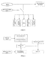
- FIG. 2 is a structural schematic diagram of a system where only a battery is used for supplying power in the specific example.
- the battery supplies power to each component of the mobile phone, and all energy is consumed from here.
- FIG. 3 is a structural schematic diagram of a system for implementing ultra-long standby in a specific example.
- a solar power supply apparatus is disposed on a rear side of a mobile phone
- an analog switch is disposed between the mobile phone battery and the solar power supply apparatus
- the battery and solar power supply apparatus form two input paths of an output circuit
- the output circuit supplies power to a preset module in the terminal
- another output circuit formed by the battery still supplies power to other modules in the terminal.
- the system is disposed on a battery path by default, and the battery supplies power to each component.
- the general purpose input output (GPIO) of the system When detecting that the solar power supply apparatus converts electrical energy, the general purpose input output (GPIO) of the system generates a pulse signal to control the analog switch to switch the input paths to the solar power supply apparatus so that the solar power supply apparatus supplies power to the module that matches the power supply voltage and solar input voltage.
- the module that matches the power supply voltage and solar input voltage may be an LCD backlight, keyboard backlight, radio frequency PA, or motor module.
- the solar power supply apparatus absorbs solar energy and converts it through a photoelectric conversion module into electrical energy for output, and the analog switch is controlled to switch the input paths to the solar power supply apparatus so that the solar power supply apparatus supplies power to the module that matches the power supply voltage and solar input voltage, reducing consumption of the battery.
- the analog switch may be further used to switch the solar power supply apparatus to the recharging path, and the recharging path is used to recharge the battery in the terminal, thereby further reducing consumption of the battery and prolonging the terminal standby time.
- FIG. 4 is a structural schematic diagram of the ultra-long standby terminal according to the embodiment.
- the terminal includes:
- the path switching unit 44 includes:
- analog switch may further include another recharging path, where the recharging path is configured to recharge the battery.
- the terminal may further include:
- the solar power supply apparatus may be formed by a solar panel and a photoelectric conversion module, and disposed on a rear side of the terminal. During the specific implementation process, the solar power supply apparatus may also be disposed in another position of the terminal; the solar panel and photoelectric conversion module may be implemented by common means in the prior art, which is not limited herein.
- the module that matches the power supply voltage and solar input voltage may include one or more of the following: screen backlight module, keyboard backlight module, radio frequency PA module, motor module, and audio power effect module.
- all the included units are classified only according to the function logic, but are not limited to the classification method as long as the corresponding functions are able to be implemented.
- the names of all the function units are only used for distinguishing between each other, but are not configured to limit the protection scope.
- the program may be stored in a computer readable storage medium.
- the storage medium may include a read-only memory, a magnetic disk, and an optical disc, which is able to be read by a computer.
- the embodiments of the present invention are able to implement 7 ultra-long standby for a terminal by using solar energy, thereby significantly improving user experience.
Landscapes
- Engineering & Computer Science (AREA)
- Power Engineering (AREA)
- Business, Economics & Management (AREA)
- Emergency Management (AREA)
- Computer Networks & Wireless Communication (AREA)
- Signal Processing (AREA)
- Charge And Discharge Circuits For Batteries Or The Like (AREA)
- Direct Current Feeding And Distribution (AREA)
- Power Sources (AREA)
Abstract
Description
- The present invention relates to the field of terminal devices, and in particular to, an ultra-long standby method and an ultra-long standby terminal.
- Currently, as the photovoltaic industry is growing rapidly, the solar cells that are based on crystalline silicon are dominating the photovoltaic market, and enjoy a market share of more than 90%. At present, the solar technology has been widely used in devices such as water heaters, street lamps, and mobile phones.
- Currently, for applications of the solar technology on terminal, for example mobile phones, three application schemes are available: 1. mobile phones with solar panels; 2. mobile phones with solar expansion slots; 3. mobile phones that are recharged by directly using solar chargers.
- In the solutions according to the prior art, however, the solar conversion rate is only about 15% now in the industry, which becomes a bottleneck for applications in portable terminal products; the normal recharging temperature for a common lithium-ion battery is 0 to 45 degrees Celsius. If a terminal is solar recharged by exposure under the sun, the surface temperature of the terminal rises (under strong sunlight radiation, the surface temperature may reach up to 60 to 70 degrees Celsius), resulting in a large impact on the lithium-ion battery performance. The capacity of the lithium-ion battery attenuates, shortening the standby time of the terminal and affecting user experience.
- The purpose of the present invention is to provide an ultra-long standby method and an ultra-long standby terminal that are able to use solar energy to implement ultra-long standby for a terminal, thereby significantly improving user experience.
- An ultra-long standby method is provided, including:
- disposing a solar power supply apparatus on a terminal and disposing an analog switch between the solar power supply apparatus and a battery within the terminal, where the solar power supply apparatus and the battery form two input paths of an output circuit, the output circuit supplies power to a preset module, and the preset module is a module that matches a power supply voltage and a solar input voltage;
- detecting whether or not the solar power supply apparatus continues to convert electrical energy; and
- controlling, upon detecting that the solar power supply apparatus continues to convert electrical energy, the analog switch to switch the input paths to the solar power supply apparatus so that the solar power supply apparatus supplies power to the preset module.
- An ultra-long standby terminal is provided, including:
- a solar power supply apparatus disposed on a terminal, configured to supply power to a terminal module that matches a power supply voltage and a solar input voltage;
- an analog switch, disposed between the solar power supply apparatus and a battery within the terminal; where, the solar power supply apparatus and the battery form two input paths of an output circuit, the output circuit supplies power to a preset module, and the preset module is a module that matches a power supply voltage and a solar input voltage;
- a detecting unit, configured to detect whether or not the solar power supply apparatus continues to convert electrical energy; and
- a path switching unit, configured to control, when the detecting unit detects that the solar power supply apparatus continues to convert electrical energy, the analog switch to switch the input paths to the solar power supply apparatus so that the solar power supply apparatus supplies power to the preset module.
- From the provided technical solutions, it may be seen that, the mehod: disposes a solar power supply apparatus on a terminal and disposesan analog switch between the solar power supply apparatus and a battery within the terminal, where the solar power supply apparatus and the battery form two input paths of an output circuit, the output circuit supplies power to a preset module, and the preset module is a module that matches a power supply voltage and a solar input voltage; detects whether or not the solar power supply apparatus continues to convert electrical energy; and controls, upon detecting that the solar power supply apparatus continues to convert electrical energy, the analog switch to switch the input paths to the solar power supply apparatus so that the solar power supply apparatus supplies power to the preset module, thereby using solar energy to implementing ultra-long standby for a terminal, and significantly improving user experience.
-
-
FIG. 1 is a schematic flowchart of an ultra-long standby method according to an embodiment of the present invention; -
FIG. 2 is a structural schematic diagram of a system where only a battery is used for supplying power in a specific example according to an embodiment of the present invention; -
FIG. 3 is a structural schematic diagram of a system for implementing ultra-long standby in a specific example according to an embodiment of the present invention; and -
FIG. 4 is a structural schematic diagram of an ultra-long standby terminal according to an embodiment of the present invention. - Embodiments of the present invention provide an ultra-long standby method and an ultra-long standby terminal, where specifically solar energy is used as an auxiliary power supply source in addition to the battery of a terminal, minimizing consumption of the battery in various applications of the terminal, thereby indirectly implementing ultra-long standby for the terminal, and significantly improving user experience.
- To better describe the embodiments of the present invention, the following describes a specific implementation manner of the present invention with reference to drawings.
FIG. 1 is a schematic flowchart of an ultra-long standby method according to an embodiment of the present invention. The method includes: - Step 11: Dispose a solar power supply apparatus on a terminal and dispose an analog switch between the solar power supply apparatus and a battery within the terminal.
- In this step, the solar power supply apparatus may be formed by a solar panel and a photoelectric conversion module, and may be disposed on a rear side of the terminal. During the specific implementation process, the solar power supply apparatus may also be disposed in another position of the terminal; the solar panel and photoelectric conversion module may be implemented by common means in the prior art, which is not limited herein.
- For the disposed analog switch, the battery and the solar power supply apparatus form two input paths of an output circuit, the output circuit supplies power to a preset module in the terminal, and another output circuit formed by the battery still supplies power to other modules in the terminal. In this embodiment, the power of the system may be supplied by the input paths of the battery by default; of course, during the specific implementation process, the system may also be set to null by default, and switch to the input path for power supply according to the specific use condition.
- The terminal may include: a mobile phone, tablet computer, or laptop computer, or may also include other terminal devices that use a battery to supply power.
- Step 12: Detect whether or not the solar power supply apparatus continues to convert electrical energy.
- In this step, a voltage detection apparatus may be used for detection. When the voltage detection apparatus detects that the solar power supply apparatus continues to generate voltage, it can be determined that the solar power supply apparatus continues to convert electrical energy.
- Of course, during the specific implementation process, other detection apparatuses, for example, a current detection apparatus, may be used for implementation, which is not limited herein.
- Step 13: Upon detecting that the solar power supply apparatus continues to convert electrical energy, control the analog switch to switch the input paths to the solar power supply apparatus so that the solar power supply apparatus supplies power to the preset module that matches a power supply voltage and a solar input voltage.
- In this step, when it is detected by using the operation in
step 12 that the solar power supply apparatus converts electrical energy, the analog switch may be controlled to switch the input paths to the solar power supply apparatus so that the solar power supply apparatus supplies power to the preset module that matches the power supply voltage and solar input voltage, whereas the terminal battery still supplies power to other modules in the terminal. In this manner, the consumption of the battery in various applications of the terminal is able to be minimized, thereby indirectly implementing ultra-long standby for the terminal. - During the specific implementation process, a method for controlling the analog switch may be sending a pulse signal to the analog switch to activate and control shutdown of the analog switch, thereby switching the input paths to the solar power supply apparatus so that the solar power supply apparatus supplies power to the module that matches the power supply voltage and solar input voltage.
- The preset module that matches the power supply voltage and solar input voltage may include one or more of the following: screen backlight module, keyboard backlight module, radio frequency PA module, motor module, and audio power effect module. Specific selection of the modules may be classified according to requirements for the power supply voltage. Modules, for example, screen backlight module and keyboard backlight module, with high requirements are allocated to a group with high priority, and are preferentially powered by the solar power supply apparatus.
- In addition, during the specific implementation process, the terminal is classified into a use state and a standby state. When the terminal is in the use state, the operation according to
step 12 is performed; when the terminal is in the standby state, the analog switch may be further used to switch the solar power supply apparatus to the recharging path, and the recharging path is used to recharge the battery in the terminal, thereby further reducing consumption of the battery, and prolonging the terminal standby time. The method for determining that the terminal is in the use state or standby state may be by detecting whether the terminal is in screen lock; upon detecting that the terminal screen is locked, it may be further determined that the terminal is in the standby state. Of course, other methods that are able to determine that the terminal is in the use state or standby state in this field are also feasible, and are not limited in this embodiment. - The specific implementation means may be adding a branch to the analog switch, where the branch is connected to the recharging path; upon detecting that the terminal is in the standby state and is not used, another pulse signal may be sent to the analog switch to activate and control the analog switch to switch to the recharging path, so as to use this recharging path to recharge the battery in the terminal.
- A solar implementation scheme on a mobile phone is used as an example.
FIG. 2 is a structural schematic diagram of a system where only a battery is used for supplying power in the specific example. InFIG. 2 , the battery supplies power to each component of the mobile phone, and all energy is consumed from here. -
FIG. 3 is a structural schematic diagram of a system for implementing ultra-long standby in a specific example. InFIG. 3 , a solar power supply apparatus is disposed on a rear side of a mobile phone, an analog switch is disposed between the mobile phone battery and the solar power supply apparatus, the battery and solar power supply apparatus form two input paths of an output circuit, the output circuit supplies power to a preset module in the terminal, and another output circuit formed by the battery still supplies power to other modules in the terminal. The system is disposed on a battery path by default, and the battery supplies power to each component. - When detecting that the solar power supply apparatus converts electrical energy, the general purpose input output (GPIO) of the system generates a pulse signal to control the analog switch to switch the input paths to the solar power supply apparatus so that the solar power supply apparatus supplies power to the module that matches the power supply voltage and solar input voltage. The module that matches the power supply voltage and solar input voltage may be an LCD backlight, keyboard backlight, radio frequency PA, or motor module.
- In addition, according to how a user uses a mobile phone, in the scenario where the user normally uses the mobile phone outdoor: the solar power supply apparatus absorbs solar energy and converts it through a photoelectric conversion module into electrical energy for output, and the analog switch is controlled to switch the input paths to the solar power supply apparatus so that the solar power supply apparatus supplies power to the module that matches the power supply voltage and solar input voltage, reducing consumption of the battery.
- In the scenario where the user does not use the mobile phone outdoor, that is, the mobile phone is in the standby state: the analog switch may be further used to switch the solar power supply apparatus to the recharging path, and the recharging path is used to recharge the battery in the terminal, thereby further reducing consumption of the battery and prolonging the terminal standby time.
- An embodiment of the present invention further provides an ultra-long standby terminal.
FIG. 4 is a structural schematic diagram of the ultra-long standby terminal according to the embodiment. The terminal includes: - a solar
power supply apparatus 41 disposed on a terminal, configured to supply power to a terminal module that matches a power supply voltage and a solar input voltage; - an
analog switch 42, disposed between abattery 43 within the terminal and the solarpower supply apparatus 41; where, thebattery 43 and the solarpower supply apparatus 41 form two input paths of an output circuit, the output circuit supplies power to a preset module, and another output circuit formed by thebattery 43 still supplies power to other modules in the terminal; for the specific implementation manner, refer to the description instep 11 of the foregoing method embodiment; - a detecting
unit 44, configured to detect whether or not the solarpower supply apparatus 41 continues to convert electrical energy; for the specific implementation manner, refer to the description instep 12 of the foregoing method embodiment; and - a
path switching unit 45, configured to control, when the detectingunit 44 detects that the solarpower supply apparatus 41 continues to convert electrical energy, theanalog switch 42 to switch the input paths to the solarpower supply apparatus 41 so that the solarpower supply apparatus 41 supplies power to a module that matches a power supply voltage and a solar input voltage. For the specific implementation manner, refer to the description instep 13 of the foregoing method embodiment. - The
path switching unit 44 includes: - a
pulse control module 451, configured to control, by sending a pulse signal to the analog switch, the analog switch to switch the input paths to the solar power supply apparatus. For the specific implementation manner, refer to the description of the foregoing method embodiment. - In addition, the analog switch may further include another recharging path, where the recharging path is configured to recharge the battery. The terminal may further include:
- a
standby determining unit 46, configured to detect whether the terminal is in screen lock; upon detecting that the terminal screen is locked, determine that the terminal is in the standby state; and - a recharging
path switching unit 47, configured to switch, when determining that the terminal is in the standby state, the solarpower supply apparatus 41 through theanalog switch 42 to another recharging path to supply power to the battery. For the specific implementation manner, refer to the description of the foregoing method embodiment. - The solar power supply apparatus may be formed by a solar panel and a photoelectric conversion module, and disposed on a rear side of the terminal. During the specific implementation process, the solar power supply apparatus may also be disposed in another position of the terminal; the solar panel and photoelectric conversion module may be implemented by common means in the prior art, which is not limited herein.
- The module that matches the power supply voltage and solar input voltage may include one or more of the following: screen backlight module, keyboard backlight module, radio frequency PA module, motor module, and audio power effect module.
- It should be noted that in the foregoing embodiment, all the included units are classified only according to the function logic, but are not limited to the classification method as long as the corresponding functions are able to be implemented. In addition, the names of all the function units are only used for distinguishing between each other, but are not configured to limit the protection scope.
- In addition, a person of ordinary skill in the art may understand that all or part of the steps in the method embodiments may be implemented by a computer program instructing related hardware. The program may be stored in a computer readable storage medium. The storage medium may include a read-only memory, a magnetic disk, and an optical disc, which is able to be read by a computer.
- In summary, the embodiments of the present invention are able to implement 7 ultra-long standby for a terminal by using solar energy, thereby significantly improving user experience.
- The foregoing descriptions are merely preferred specific embodiments of the present invention, but are not intended to limit the protection scope of the present invention. Any variation or replacement readily figured out by a person skilled in the art within the technical scope disclosed in the present invention shall fall within the protection scope of the present invention. Therefore, the protection scope of the present invention is subject to the appended claims.
Claims (9)
- An ultra-long standby method, comprising:disposing a solar power supply apparatus on a terminal and disposing an analog switch between the solar power supply apparatus and a battery within the terminal, wherein the solar power supply apparatus and the battery form two input paths of an output circuit, the output circuit supplies power to a preset module, and the preset module is a module that matches a power supply voltage and a solar input voltage;detecting whether or not the solar power supply apparatus continues to convert electrical energy; andupon detecting that the solar power supply apparatus continues to convert electrical energy, controlling the analog switch to switch the input paths to the solar power supply apparatus so that the solar power supply apparatus supplies power to the preset module.
- The ultra-long standby method according to claim 1, wherein the controlling the analog switch to switch the input paths to the solar power supply apparatus comprises:by sending a pulse signal to the analog switch, controlling the analog switch to switch the input paths to the solar power supply apparatus.
- The ultra-long standby method according to claim 1, further comprising:detecting whether the terminal is in screen lock; upon detecting that the terminal screen is locked, determining that the terminal is in a standby state; andswitching the solar power supply apparatus through the analog switch to another recharging path to supply power to the battery.
- An ultra-long standby terminal, comprising:a solar power supply apparatus disposed on a terminal, configured to supply power to a terminal module that matches a power supply voltage and a solar input voltage;an analog switch, disposed between the solar power supply apparatus and a battery within the terminal; wherein, the solar power supply apparatus and the battery form two input paths of an output circuit, the output circuit supplies power to a preset module in the terminal, and the preset module is a module that matches a power supply voltage and a solar input voltage;a detecting unit, configured to detect whether or not the solar power supply apparatus continues to convert electrical energy; anda path switching unit, configured to control, when the detecting unit detects that the solar power supply apparatus continues to convert electrical energy, the analog switch to switch the input paths to the solar power supply apparatus so that the solar power supply apparatus supplies power to the preset module.
- The ultra-long standby terminal according to claim 4, wherein the path switching unit comprises:a pulse control module, configured to control, by sending a pulse signal to the analog switch, the analog switch to switch the input paths to the solar power supply apparatus.
- The ultra-long standby terminal according to claim 4, wherein the analog switch further comprises another recharging path, the recharging path is configured to recharge the battery, and the terminal further comprises:a standby determining unit, configured to detect whether the terminal is in screen lock; upon detecting that the terminal screen is locked, determine that the terminal is in a standby state; anda recharging path switching unit, configured to switch, when determining that the terminal is in the standby state, the solar power supply apparatus through the analog switch to the another recharging path to supply power to the battery.
- The ultra-long standby terminal according to any one of claims 4 to 6, wherein:the terminal comprises: a mobile phone, a tablet computer, or a laptop computer.
- The ultra-long standby terminal according to claim 4, wherein:the solar power supply apparatus is formed by a solar panel and a photoelectric conversion module, and disposed on a rear side of the terminal.
- The ultra-long standby terminal according to claim 4, wherein the preset module may comprise one or more of the following:screen backlight module, keyboard backlight module, radio frequency PA module, motor module, and audio power effect module.
Applications Claiming Priority (1)
| Application Number | Priority Date | Filing Date | Title |
|---|---|---|---|
| PCT/CN2011/077804 WO2011137874A2 (en) | 2011-07-29 | 2011-07-29 | Ultra-long standby method and ultra-long standby terminal |
Publications (2)
| Publication Number | Publication Date |
|---|---|
| EP2712048A2 true EP2712048A2 (en) | 2014-03-26 |
| EP2712048A4 EP2712048A4 (en) | 2014-07-02 |
Family
ID=44904158
Family Applications (1)
| Application Number | Title | Priority Date | Filing Date |
|---|---|---|---|
| EP11777293.9A Withdrawn EP2712048A4 (en) | 2011-07-29 | 2011-07-29 | ULTRA LONG HOLDING METHOD AND TERMINAL |
Country Status (4)
| Country | Link |
|---|---|
| US (1) | US20140117765A1 (en) |
| EP (1) | EP2712048A4 (en) |
| CN (1) | CN102318178A (en) |
| WO (1) | WO2011137874A2 (en) |
Family Cites Families (9)
| Publication number | Priority date | Publication date | Assignee | Title |
|---|---|---|---|---|
| US6339311B1 (en) * | 2000-11-15 | 2002-01-15 | Lsi Logic Corporation | Photovoltaic power source for portable electronic device |
| CN1332286C (en) * | 2003-11-24 | 2007-08-15 | 佛山市顺德区顺达电脑厂有限公司 | Electric power administration arrangement and method for portable computers with auxiliary power supply |
| CN100421488C (en) * | 2005-05-10 | 2008-09-24 | 英华达(上海)电子有限公司 | Cell phone with solar power |
| JP2006316601A (en) * | 2005-05-14 | 2006-11-24 | Masahiko Nakamura | Cellular phone operation type solar battery lock for bicycle |
| CN101026312B (en) * | 2006-02-25 | 2010-10-06 | 鸿富锦精密工业(深圳)有限公司 | Portable electronic device with solar charging function |
| KR101552270B1 (en) * | 2009-02-13 | 2015-09-11 | 삼성전자주식회사 | A mobile terminal including a solar cell part and a power control method thereof |
| EP2441152A2 (en) * | 2009-06-08 | 2012-04-18 | Techtium Ltd. | Solar cell charging control |
| GB0911659D0 (en) * | 2009-07-06 | 2009-08-12 | Caps Innovations Ltd | Power supplies |
| CN101819731B (en) * | 2010-01-19 | 2011-09-14 | 苏州佳世达电通有限公司 | Display with solar module and power supply method thereof |
-
2011
- 2011-07-29 CN CN2011800015482A patent/CN102318178A/en active Pending
- 2011-07-29 EP EP11777293.9A patent/EP2712048A4/en not_active Withdrawn
- 2011-07-29 WO PCT/CN2011/077804 patent/WO2011137874A2/en not_active Ceased
-
2013
- 2013-12-26 US US14/140,781 patent/US20140117765A1/en not_active Abandoned
Also Published As
| Publication number | Publication date |
|---|---|
| WO2011137874A2 (en) | 2011-11-10 |
| WO2011137874A3 (en) | 2012-06-21 |
| EP2712048A4 (en) | 2014-07-02 |
| CN102318178A (en) | 2012-01-11 |
| US20140117765A1 (en) | 2014-05-01 |
Similar Documents
| Publication | Publication Date | Title |
|---|---|---|
| US9166434B2 (en) | Universal charger | |
| US8022571B2 (en) | Power management circuitry and solar cells | |
| CN102096456B (en) | The department of computer science with solar-electricity source unit unifies and controls the method for this computer system | |
| CN101877494B (en) | Solar energy storage system and method | |
| CN203522279U (en) | Multifunctional mobile power supply | |
| US8653795B2 (en) | Charger circuit | |
| CN102055037A (en) | Mobile electronic device and electric quantity management method of battery module thereof | |
| JP2007329997A (en) | Charging circuit, charging circuit operation control method, and power supply device | |
| US20120235486A1 (en) | Photovoltaic inverter and method for controlling photovoltaic inverter | |
| CN102368633B (en) | Solar energy and mains supply complementation controller | |
| CN101789609B (en) | Battery equalization system, method and circuit | |
| US8890359B2 (en) | Power supply system and container data center including same | |
| EP3518370A1 (en) | Dual-battery mobile terminal and wireless charging system thereof | |
| CN101651238A (en) | solar charger | |
| CN104868840A (en) | Photovoltaic energy storage inverter off-grid MPPT perturbation method | |
| CN201985613U (en) | Solar controller with commercial power complementation | |
| CN201118929Y (en) | Bluetooth headset with solar power supply function | |
| US8253384B2 (en) | Electronic device having power management assembly | |
| WO2013018600A1 (en) | Power supply system | |
| US8436574B2 (en) | Solar power supply system and driving method of same | |
| CN114285128B (en) | Outdoor equipment power supply control circuit, outdoor equipment power supply system and outdoor equipment | |
| JP2010226857A (en) | Power supply system | |
| JP5456328B2 (en) | Electronic device and charge control method | |
| EP2712048A2 (en) | Ultra-long standby method and ultra-long standby terminal | |
| CN103928952A (en) | Charging system and charging method thereof |
Legal Events
| Date | Code | Title | Description |
|---|---|---|---|
| PUAI | Public reference made under article 153(3) epc to a published international application that has entered the european phase |
Free format text: ORIGINAL CODE: 0009012 |
|
| 17P | Request for examination filed |
Effective date: 20131219 |
|
| AK | Designated contracting states |
Kind code of ref document: A2 Designated state(s): AL AT BE BG CH CY CZ DE DK EE ES FI FR GB GR HR HU IE IS IT LI LT LU LV MC MK MT NL NO PL PT RO RS SE SI SK SM TR |
|
| A4 | Supplementary search report drawn up and despatched |
Effective date: 20140603 |
|
| RIC1 | Information provided on ipc code assigned before grant |
Ipc: H04W 88/02 20090101ALI20140527BHEP Ipc: H02J 7/32 20060101AFI20140527BHEP |
|
| DAX | Request for extension of the european patent (deleted) | ||
| STAA | Information on the status of an ep patent application or granted ep patent |
Free format text: STATUS: THE APPLICATION HAS BEEN WITHDRAWN |
|
| 18W | Application withdrawn |
Effective date: 20141211 |