EP2712046A1 - Battery control device - Google Patents
Battery control device Download PDFInfo
- Publication number
- EP2712046A1 EP2712046A1 EP11865666.9A EP11865666A EP2712046A1 EP 2712046 A1 EP2712046 A1 EP 2712046A1 EP 11865666 A EP11865666 A EP 11865666A EP 2712046 A1 EP2712046 A1 EP 2712046A1
- Authority
- EP
- European Patent Office
- Prior art keywords
- battery pack
- single cell
- permitted
- range
- circuit voltage
- Prior art date
- Legal status (The legal status is an assumption and is not a legal conclusion. Google has not performed a legal analysis and makes no representation as to the accuracy of the status listed.)
- Granted
Links
Images


Classifications
-
- B—PERFORMING OPERATIONS; TRANSPORTING
- B60—VEHICLES IN GENERAL
- B60L—PROPULSION OF ELECTRICALLY-PROPELLED VEHICLES; SUPPLYING ELECTRIC POWER FOR AUXILIARY EQUIPMENT OF ELECTRICALLY-PROPELLED VEHICLES; ELECTRODYNAMIC BRAKE SYSTEMS FOR VEHICLES IN GENERAL; MAGNETIC SUSPENSION OR LEVITATION FOR VEHICLES; MONITORING OPERATING VARIABLES OF ELECTRICALLY-PROPELLED VEHICLES; ELECTRIC SAFETY DEVICES FOR ELECTRICALLY-PROPELLED VEHICLES
- B60L58/00—Methods or circuit arrangements for monitoring or controlling batteries or fuel cells, specially adapted for electric vehicles
- B60L58/10—Methods or circuit arrangements for monitoring or controlling batteries or fuel cells, specially adapted for electric vehicles for monitoring or controlling batteries
- B60L58/12—Methods or circuit arrangements for monitoring or controlling batteries or fuel cells, specially adapted for electric vehicles for monitoring or controlling batteries responding to state of charge [SoC]
- B60L58/14—Preventing excessive discharging
-
- B—PERFORMING OPERATIONS; TRANSPORTING
- B60—VEHICLES IN GENERAL
- B60L—PROPULSION OF ELECTRICALLY-PROPELLED VEHICLES; SUPPLYING ELECTRIC POWER FOR AUXILIARY EQUIPMENT OF ELECTRICALLY-PROPELLED VEHICLES; ELECTRODYNAMIC BRAKE SYSTEMS FOR VEHICLES IN GENERAL; MAGNETIC SUSPENSION OR LEVITATION FOR VEHICLES; MONITORING OPERATING VARIABLES OF ELECTRICALLY-PROPELLED VEHICLES; ELECTRIC SAFETY DEVICES FOR ELECTRICALLY-PROPELLED VEHICLES
- B60L3/00—Electric devices on electrically-propelled vehicles for safety purposes; Monitoring operating variables, e.g. speed, deceleration or energy consumption
- B60L3/0023—Detecting, eliminating, remedying or compensating for drive train abnormalities, e.g. failures within the drive train
- B60L3/0046—Detecting, eliminating, remedying or compensating for drive train abnormalities, e.g. failures within the drive train relating to electric energy storage systems, e.g. batteries or capacitors
-
- B—PERFORMING OPERATIONS; TRANSPORTING
- B60—VEHICLES IN GENERAL
- B60L—PROPULSION OF ELECTRICALLY-PROPELLED VEHICLES; SUPPLYING ELECTRIC POWER FOR AUXILIARY EQUIPMENT OF ELECTRICALLY-PROPELLED VEHICLES; ELECTRODYNAMIC BRAKE SYSTEMS FOR VEHICLES IN GENERAL; MAGNETIC SUSPENSION OR LEVITATION FOR VEHICLES; MONITORING OPERATING VARIABLES OF ELECTRICALLY-PROPELLED VEHICLES; ELECTRIC SAFETY DEVICES FOR ELECTRICALLY-PROPELLED VEHICLES
- B60L3/00—Electric devices on electrically-propelled vehicles for safety purposes; Monitoring operating variables, e.g. speed, deceleration or energy consumption
- B60L3/04—Cutting off the power supply under fault conditions
-
- B—PERFORMING OPERATIONS; TRANSPORTING
- B60—VEHICLES IN GENERAL
- B60L—PROPULSION OF ELECTRICALLY-PROPELLED VEHICLES; SUPPLYING ELECTRIC POWER FOR AUXILIARY EQUIPMENT OF ELECTRICALLY-PROPELLED VEHICLES; ELECTRODYNAMIC BRAKE SYSTEMS FOR VEHICLES IN GENERAL; MAGNETIC SUSPENSION OR LEVITATION FOR VEHICLES; MONITORING OPERATING VARIABLES OF ELECTRICALLY-PROPELLED VEHICLES; ELECTRIC SAFETY DEVICES FOR ELECTRICALLY-PROPELLED VEHICLES
- B60L58/00—Methods or circuit arrangements for monitoring or controlling batteries or fuel cells, specially adapted for electric vehicles
- B60L58/10—Methods or circuit arrangements for monitoring or controlling batteries or fuel cells, specially adapted for electric vehicles for monitoring or controlling batteries
- B60L58/12—Methods or circuit arrangements for monitoring or controlling batteries or fuel cells, specially adapted for electric vehicles for monitoring or controlling batteries responding to state of charge [SoC]
- B60L58/15—Preventing overcharging
-
- B—PERFORMING OPERATIONS; TRANSPORTING
- B60—VEHICLES IN GENERAL
- B60L—PROPULSION OF ELECTRICALLY-PROPELLED VEHICLES; SUPPLYING ELECTRIC POWER FOR AUXILIARY EQUIPMENT OF ELECTRICALLY-PROPELLED VEHICLES; ELECTRODYNAMIC BRAKE SYSTEMS FOR VEHICLES IN GENERAL; MAGNETIC SUSPENSION OR LEVITATION FOR VEHICLES; MONITORING OPERATING VARIABLES OF ELECTRICALLY-PROPELLED VEHICLES; ELECTRIC SAFETY DEVICES FOR ELECTRICALLY-PROPELLED VEHICLES
- B60L58/00—Methods or circuit arrangements for monitoring or controlling batteries or fuel cells, specially adapted for electric vehicles
- B60L58/10—Methods or circuit arrangements for monitoring or controlling batteries or fuel cells, specially adapted for electric vehicles for monitoring or controlling batteries
- B60L58/18—Methods or circuit arrangements for monitoring or controlling batteries or fuel cells, specially adapted for electric vehicles for monitoring or controlling batteries of two or more battery modules
- B60L58/21—Methods or circuit arrangements for monitoring or controlling batteries or fuel cells, specially adapted for electric vehicles for monitoring or controlling batteries of two or more battery modules having the same nominal voltage
-
- G—PHYSICS
- G01—MEASURING; TESTING
- G01R—MEASURING ELECTRIC VARIABLES; MEASURING MAGNETIC VARIABLES
- G01R31/00—Arrangements for testing electric properties; Arrangements for locating electric faults; Arrangements for electrical testing characterised by what is being tested not provided for elsewhere
- G01R31/36—Arrangements for testing, measuring or monitoring the electrical condition of accumulators or electric batteries, e.g. capacity or state of charge [SoC]
- G01R31/382—Arrangements for monitoring battery or accumulator variables, e.g. SoC
- G01R31/3835—Arrangements for monitoring battery or accumulator variables, e.g. SoC involving only voltage measurements
-
- H—ELECTRICITY
- H01—ELECTRIC ELEMENTS
- H01M—PROCESSES OR MEANS, e.g. BATTERIES, FOR THE DIRECT CONVERSION OF CHEMICAL ENERGY INTO ELECTRICAL ENERGY
- H01M10/00—Secondary cells; Manufacture thereof
- H01M10/42—Methods or arrangements for servicing or maintenance of secondary cells or secondary half-cells
- H01M10/425—Structural combination with electronic components, e.g. electronic circuits integrated to the outside of the casing
-
- H—ELECTRICITY
- H01—ELECTRIC ELEMENTS
- H01M—PROCESSES OR MEANS, e.g. BATTERIES, FOR THE DIRECT CONVERSION OF CHEMICAL ENERGY INTO ELECTRICAL ENERGY
- H01M10/00—Secondary cells; Manufacture thereof
- H01M10/42—Methods or arrangements for servicing or maintenance of secondary cells or secondary half-cells
- H01M10/48—Accumulators combined with arrangements for measuring, testing or indicating the condition of cells, e.g. the level or density of the electrolyte
-
- H—ELECTRICITY
- H02—GENERATION; CONVERSION OR DISTRIBUTION OF ELECTRIC POWER
- H02J—ELECTRIC POWER NETWORKS; CIRCUIT ARRANGEMENTS OR SYSTEMS FOR SUPPLYING OR DISTRIBUTING ELECTRIC POWER; SYSTEMS FOR STORING ELECTRIC ENERGY
- H02J7/00—Circuit arrangements for charging or discharging batteries or for supplying loads from batteries
- H02J7/50—Circuit arrangements for charging or discharging batteries or for supplying loads from batteries acting upon multiple batteries simultaneously or sequentially
- H02J7/52—Circuit arrangements for charging or discharging batteries or for supplying loads from batteries acting upon multiple batteries simultaneously or sequentially for charge balancing, e.g. equalisation of charge between batteries
-
- H—ELECTRICITY
- H02—GENERATION; CONVERSION OR DISTRIBUTION OF ELECTRIC POWER
- H02J—ELECTRIC POWER NETWORKS; CIRCUIT ARRANGEMENTS OR SYSTEMS FOR SUPPLYING OR DISTRIBUTING ELECTRIC POWER; SYSTEMS FOR STORING ELECTRIC ENERGY
- H02J7/00—Circuit arrangements for charging or discharging batteries or for supplying loads from batteries
- H02J7/60—Circuit arrangements for charging or discharging batteries or for supplying loads from batteries including safety or protection arrangements
- H02J7/61—Circuit arrangements for charging or discharging batteries or for supplying loads from batteries including safety or protection arrangements against overcharge
-
- H—ELECTRICITY
- H02—GENERATION; CONVERSION OR DISTRIBUTION OF ELECTRIC POWER
- H02J—ELECTRIC POWER NETWORKS; CIRCUIT ARRANGEMENTS OR SYSTEMS FOR SUPPLYING OR DISTRIBUTING ELECTRIC POWER; SYSTEMS FOR STORING ELECTRIC ENERGY
- H02J7/00—Circuit arrangements for charging or discharging batteries or for supplying loads from batteries
- H02J7/60—Circuit arrangements for charging or discharging batteries or for supplying loads from batteries including safety or protection arrangements
- H02J7/63—Circuit arrangements for charging or discharging batteries or for supplying loads from batteries including safety or protection arrangements against overdischarge
-
- H—ELECTRICITY
- H02—GENERATION; CONVERSION OR DISTRIBUTION OF ELECTRIC POWER
- H02J—ELECTRIC POWER NETWORKS; CIRCUIT ARRANGEMENTS OR SYSTEMS FOR SUPPLYING OR DISTRIBUTING ELECTRIC POWER; SYSTEMS FOR STORING ELECTRIC ENERGY
- H02J7/00—Circuit arrangements for charging or discharging batteries or for supplying loads from batteries
- H02J7/60—Circuit arrangements for charging or discharging batteries or for supplying loads from batteries including safety or protection arrangements
- H02J7/65—Circuit arrangements for charging or discharging batteries or for supplying loads from batteries including safety or protection arrangements against overtemperature
-
- B—PERFORMING OPERATIONS; TRANSPORTING
- B60—VEHICLES IN GENERAL
- B60L—PROPULSION OF ELECTRICALLY-PROPELLED VEHICLES; SUPPLYING ELECTRIC POWER FOR AUXILIARY EQUIPMENT OF ELECTRICALLY-PROPELLED VEHICLES; ELECTRODYNAMIC BRAKE SYSTEMS FOR VEHICLES IN GENERAL; MAGNETIC SUSPENSION OR LEVITATION FOR VEHICLES; MONITORING OPERATING VARIABLES OF ELECTRICALLY-PROPELLED VEHICLES; ELECTRIC SAFETY DEVICES FOR ELECTRICALLY-PROPELLED VEHICLES
- B60L2240/00—Control parameters of input or output; Target parameters
- B60L2240/40—Drive Train control parameters
- B60L2240/54—Drive Train control parameters related to batteries
- B60L2240/547—Voltage
-
- G—PHYSICS
- G01—MEASURING; TESTING
- G01R—MEASURING ELECTRIC VARIABLES; MEASURING MAGNETIC VARIABLES
- G01R31/00—Arrangements for testing electric properties; Arrangements for locating electric faults; Arrangements for electrical testing characterised by what is being tested not provided for elsewhere
- G01R31/36—Arrangements for testing, measuring or monitoring the electrical condition of accumulators or electric batteries, e.g. capacity or state of charge [SoC]
- G01R31/396—Acquisition or processing of data for testing or for monitoring individual cells or groups of cells within a battery
-
- H—ELECTRICITY
- H01—ELECTRIC ELEMENTS
- H01M—PROCESSES OR MEANS, e.g. BATTERIES, FOR THE DIRECT CONVERSION OF CHEMICAL ENERGY INTO ELECTRICAL ENERGY
- H01M10/00—Secondary cells; Manufacture thereof
- H01M10/42—Methods or arrangements for servicing or maintenance of secondary cells or secondary half-cells
- H01M10/425—Structural combination with electronic components, e.g. electronic circuits integrated to the outside of the casing
- H01M2010/4271—Battery management systems including electronic circuits, e.g. control of current or voltage to keep battery in healthy state, cell balancing
-
- H—ELECTRICITY
- H02—GENERATION; CONVERSION OR DISTRIBUTION OF ELECTRIC POWER
- H02J—ELECTRIC POWER NETWORKS; CIRCUIT ARRANGEMENTS OR SYSTEMS FOR SUPPLYING OR DISTRIBUTING ELECTRIC POWER; SYSTEMS FOR STORING ELECTRIC ENERGY
- H02J2105/00—Networks for supplying or distributing electric power characterised by their spatial reach or by the load
- H02J2105/30—Networks for supplying or distributing electric power characterised by their spatial reach or by the load the load networks being external to vehicles, i.e. exchanging power with vehicles
- H02J2105/33—Networks for supplying or distributing electric power characterised by their spatial reach or by the load the load networks being external to vehicles, i.e. exchanging power with vehicles exchanging power with road vehicles
- H02J2105/37—Networks for supplying or distributing electric power characterised by their spatial reach or by the load the load networks being external to vehicles, i.e. exchanging power with vehicles exchanging power with road vehicles exchanging power with electric vehicles [EV] or with hybrid electric vehicles [HEV]
-
- Y—GENERAL TAGGING OF NEW TECHNOLOGICAL DEVELOPMENTS; GENERAL TAGGING OF CROSS-SECTIONAL TECHNOLOGIES SPANNING OVER SEVERAL SECTIONS OF THE IPC; TECHNICAL SUBJECTS COVERED BY FORMER USPC CROSS-REFERENCE ART COLLECTIONS [XRACs] AND DIGESTS
- Y02—TECHNOLOGIES OR APPLICATIONS FOR MITIGATION OR ADAPTATION AGAINST CLIMATE CHANGE
- Y02E—REDUCTION OF GREENHOUSE GAS [GHG] EMISSIONS, RELATED TO ENERGY GENERATION, TRANSMISSION OR DISTRIBUTION
- Y02E60/00—Enabling technologies; Technologies with a potential or indirect contribution to GHG emissions mitigation
- Y02E60/10—Energy storage using batteries
-
- Y—GENERAL TAGGING OF NEW TECHNOLOGICAL DEVELOPMENTS; GENERAL TAGGING OF CROSS-SECTIONAL TECHNOLOGIES SPANNING OVER SEVERAL SECTIONS OF THE IPC; TECHNICAL SUBJECTS COVERED BY FORMER USPC CROSS-REFERENCE ART COLLECTIONS [XRACs] AND DIGESTS
- Y02—TECHNOLOGIES OR APPLICATIONS FOR MITIGATION OR ADAPTATION AGAINST CLIMATE CHANGE
- Y02T—CLIMATE CHANGE MITIGATION TECHNOLOGIES RELATED TO TRANSPORTATION
- Y02T10/00—Road transport of goods or passengers
- Y02T10/60—Other road transportation technologies with climate change mitigation effect
- Y02T10/70—Energy storage systems for electromobility, e.g. batteries
Definitions
- the present invention relates to an apparatus for controlling a battery.
- a vehicle running by using electricity as driving force is mounted with a storage battery such as a lead-acid battery, a nickel hydrogen battery or a lithium ion battery.
- a storage battery such as a lead-acid battery, a nickel hydrogen battery or a lithium ion battery.
- the electric power required when a hybrid vehicle or an electric vehicle runs is supplied by the storage battery.
- the permitted charge power and discharge power of the storage battery respectively vary according to the state of charge. If charging or discharging over the maximum permitted power is performed, overcharging or overdischarging can occur. As the state of charge (SOC) of the storage battery becomes high, the maximum permitted charge power decreases and the maximum permitted discharge power increases. Besides, as the SOC of the storage battery becomes low, the maximum permitted discharge power decreases and the permitted charge power increases. In order to safely use the storage battery, the charging and discharging control is required to be performed within a range not exceeding the maximum permitted power.
- SOC state of charge
- PTL 1 mentioned below discloses a technique in which even when a temperature variation occurs among single cells constituting a battery pack, permitted charge and discharge powers suitable for respective single cells are calculated, and charging and discharging control is optimally performed.
- PTL 2 mentioned below discloses a method in which a maximum cell voltage value and a minimum cell voltage value are detected, maximum charge power is determined by using the maximum cell voltage value, and maximum discharge power is determined by using the minimum cell voltage value.
- the permitted charge and discharge powers are obtained at each of the highest temperature Tmax and the lowest temperature Tmin of the storage battery 10, and smaller values are used.
- the position where the temperature sensor is disposed does not necessarily correspond to each of the single cells, there is a possibility that the temperature detected by the temperature sensor does not necessarily accurately correspond to the permitted charge and discharge powers of each of the single cells. Accordingly, there is a possibility that the inter-terminal voltage of each of the single cells exceeds the permitted range.
- Patent Literature 1 discloses that the state of charge of each single cell is acquired, and the charging and discharging management is performed in view of variation in the state of charge of the single cell.
- the control process for managing the state of charge of each single cell becomes complicated, and the cost can become high.
- the technique disclosed in Patent Literature 2 has also the same problems.
- the invention is made in order to solve the foregoing problem, and has an object to provide a battery control apparatus which can keep an inter-terminal voltage of each single cell within a permitted range while permitted power is controlled in units of a battery pack.
- the battery control apparatus of the invention restricts permitted power of a battery pack according to a degree of closeness of a close circuit voltage (CCV) of a single cell to an upper limit or a lower limit of a permitted range.
- CCV close circuit voltage
- the battery control apparatus of the invention when the CCV of the single cell approaches the upper limit or the lower limit of the permitted range, permitted power is suppressed to prevent exceeding this, so that the single cell can be protected. Besides, since the permitted power of the battery pack is directly controlled, the control is performed in units of a battery pack, and the load of the control process can be reduced.
- a battery pack is constructed by connecting single cells in series
- the battery pack may be constructed by connecting parallel-connected single cells in parallel, or may be constructed by connecting series-connected single cells in parallel.
- FIG. 1 is a view showing a battery control apparatus 100 of embodiment 1 of the invention and its peripheral circuit structure.
- the battery control apparatus 100 is an apparatus to monitor and control the state of a battery pack 500.
- the battery control apparatus 100 includes a single cell management part 110, a current detection part 120, a voltage detection part 130, a battery pack control part 140 and a storage part 170.
- the battery pack 500 is constructed such that plural single cells 510 each of which can store and discharge electric energy (charging and discharging of DC power) are electrically connected in series.
- the single cells 510 constituting the battery pack 500 are grouped by a specified number of units for execution of state management and control.
- the grouped single cells 510 are electrically connected in series, and constitute single cell groups 520a and 520b.
- the number of single cells 510 constituting the single cell group 520 may be the same in all the single cell groups 520, or the number of single cells 510 may be different among the single cell groups 520.
- the single cell management part 110 monitors the states of the single cells 510 constituting the battery pack 500.
- the single cell management part 110 includes a single cell control part 111 provided for each of the single cell groups 520.
- the single cell control parts 111a and 111b are provided correspondingly to the single cell groups 520a and 520b.
- the single cell control part 111 monitors and controls the states of the single cells 510 constituting the single cell group 520.
- the four single cells 510 are electrically connected in series to constitute each of the single cell groups 520a and 520b, and the single cell groups 520a and 520b are further electrically connected in series.
- the battery pack 500 includes the eight single cells 510 in total.
- the battery pack control part 140 and the single cell management part 110 transmit and receive signals through insulation elements 160 typified by a photocoupler and signal communication units 150.
- a communication unit between the battery pack control part 140 and the single cell control parts 111a and 111b constituting the single cell management part 110 will be described.
- the single cell control parts 111a and 111b are connected in series in ascending order of potential of the single cell groups 520a and 520b respectively monitored by them.
- a signal transmitted from the battery pack control part 140 to the single cell management part 110 is inputted to the single cell control part 111a through the insulation element 160 and the signal communication unit 150.
- the output of the single cell control part 111a is inputted to the single cell control part 111b through the signal communication unit 150.
- the output of the lowest-level single cell control part 111b is transmitted to the battery pack control part 140 through the insulation element 160 and the signal communication unit 150.
- the insulation element 160 does not intervene between the single cell control part 111a and the single cell control part 111b, a signal can also be transmitted and received through the insulation element 160.
- the battery pack control part 140 performs the state detection of the single cell 510, the single cell group 520 or the battery pack 500 based on the information transmitted by the single cell management part 110, the current value inputted to and outputted from the battery pack 500, which is transmitted by the current detection part 120, the total voltage value of the battery pack 500 transmitted by the voltage detection part 130, the information previously stored in the storage part 170, and the like.
- the information outputted by the single cell management part 110 to the battery pack control part 140 includes the measurement value of the voltage and temperature of the single cell 510, and abnormal information of the single cell 510 such as overcharging, overdischarging or over temperature of the single cell 510. Further, the single cell management part 110 may output also a communication error of the single cell management part 110 itself or the single cell control part 111, and an abnormal signal in the case of physical failure typified by breaking of a harness to the battery pack control part 140. In this case, the battery pack control part 140 can perform the charging and discharging control of the battery pack 500 in view of the abnormal contents of the single cell management part 110 or the single cell control part 111.
- the information stored in the storage part 170 includes internal resistance characteristics of the battery pack 500, the single cell 510 and the single cell group 520, capacity at full charge, polarization voltage, deterioration characteristics, individual difference information, and correspondence relation between SOC and open circuit voltage (OCV). Further, characteristic information of the single cell management part 110, the single cell control part 111, the battery pack control part 140 and the like can also be previously stored. The information stored in the storage part 170 will be again described with reference to after-mentioned FIG. 3 to FIG. 5 .
- the battery pack control part 140 carries out an operation required to manage SOC of at least one single cell 510, state of health (SOH), current and power capable of being inputted and outputted, abnormal state, SOC of the single cell 510 and the like based on the measurement values and the information stored in the storage part 170. Then, based on the operation result, information is outputted to the single cell management part 110 and a vehicle control part 200.
- SOH state of health
- the vehicle control part 200 is a control apparatus superordinate to the battery pack control part 140, and connects the battery control apparatus 100 and an invertor 400 through relays 300 and 310 and based on the information transmitted by the battery pack control part 140.
- the vehicle control part 200 can issue an instruction to the battery pack control part 140 when necessary, and the battery pack control part 140 may start the process based on the instruction from the vehicle control part 200.
- the battery control apparatus 100 When a vehicle system mounted with the battery control apparatus 100 starts and runs, the battery control apparatus 100 is connected to the invertor 400 under management of the vehicle control part 200, and drives a motor generator 410 by using energy stored in the battery pack 500. At the time of regeneration, the battery pack 500 is charged by power generated by the motor generator 410.
- FIG. 2 is a view showing a circuit structure of the single cell control part 111.
- the single cell control part 111 includes a voltage detection circuit 112, a control circuit 113 and a signal input and output circuit 114.
- the voltage detection circuit 112 measures the inter-terminal voltage of each of the single cells 510.
- the control circuit 113 receives the measurement result from the voltage detection circuit 112, and transmits it to the battery pack control part 140 through the signal input and output circuit 114.
- the control circuit controls a charging operation and a discharging operation of each of the single cells 510. Since a circuit structure of the charging operation and the discharging operation is well known, its description is omitted.
- FIG. 3 is a view showing an example of an SOC table 171 stored in the storage part 170.
- the SOC table 171 is a data table describing a correspondence relation between OCV of the battery pack 500 and SOC of the battery pack 500.
- the data format may be arbitrary, for convenience of explanation, here, the data example is shown in graph format.
- the OCV is a voltage at the time of no load of the battery pack 500.
- the OCV can be acquired when the inter-terminal voltage of the single cell 510 is acquired at the timing before the relays 300 and 310 are closed or in the state where charging and discharging of the battery pack 500 is not started although the relays 300 and 310 are closed.
- the battery pack control part 140 integrates the OCV of the single cell 510 detected by the single cell control part 111 to obtain the OCV of the battery pack 500, and can obtain the SOC of the battery pack 500 by using the OCV of the battery pack 500 and the SOC table 171. Further, during the charging and discharging of the battery pack 500, the OCV is obtained by removing an internal resistance component and a polarization voltage component from the CCV, and the SOC of the battery pack 500 can be similarly obtained.
- FIG. 4 is a view showing an example of a permitted charge power table 172 stored in the storage part 170.
- the permitted charge power table 172 is a data table describing a correspondence relation between the SOC of the battery pack 500 and the permitted charge power.
- the data format may be arbitrary, for convenience of explanation, here, the data example is shown in graph format. Values of the permitted charge power table 172 are previously obtained by, for example, calculation and can be stored in the storage part 170.
- the battery pack control part 140 can acquire the permitted charge power of the battery pack 500 by using the SOC of the battery pack 500 acquired by using the SOC table 171 and the permitted charge power table 172.
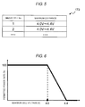
- FIG. 5 is a view showing an example of maximum CCV range data 173 stored in the storage part 170.
- the maximum CCV range data 173 is data describing a range of the maximum value of CCV of each of the single cells 510, within which the permitted power is restricted. The same value may be used for all the single cells 510, or different values may be used according to the characteristic of each of the single cells 510.
- the maximum CCV range data 173 is the data describing this range.
- each of the single cells 510 can exceed the rated voltage.
- the charge power to each of the single cells 510 is required to be individually controlled, or the permitted charge power of the whole battery pack 500 is suppressed to be sufficiently low so that the inter-terminal voltage of each of the single cells 510 falls within the rated voltage.
- a range of the inter-terminal voltage of each of the single cells 510 is previously determined within which the permitted power is restricted.
- the inter-terminal voltage of the single cell 510 is close to the lower limit value of this range, a larger charge power is permitted, and when the inter-terminal voltage is close to the upper limit value, the charge power is suppressed to be low.
- FIG. 6 is a view showing a situation in which the battery control apparatus 100 of the embodiment 1 adjusts the permitted charge power of the whole battery pack 500 in order to control the inter-terminal voltage of each of the single cells 510.
- the values described in the maximum CCV range data 173 are used for the range of the inter-terminal voltage of each of the single cells 510, within which the permitted power is restricted.
- 4.0 V to 4.4 V exemplified in FIG. 5 was used.
- the inter-terminal voltage of the single cell 510 When the inter-terminal voltage of the single cell 510 is close to the lower limit value (4.0 V) of the range within which the permitted power is restricted, a larger charge power can be permitted. Accordingly, the permitted charge power is increased.
- the inter-terminal voltage of the single cell 510 is coincident with the lower limit value (4.0 V) of the permitted range, 100% of the permitted charge power obtained from the permitted charge power table 172 is used.
- the inter-terminal voltage of the single cell 510 is close to the upper limit value (4.4 V) of the range within which the permitted power is restricted, a large charge power can not be permitted. Accordingly, the permitted charge power is decreased.
- the inter-terminal voltage of the single cell 510 is coincident with the upper limit value (4.4 V) of the permitted range, the supply of the charge power to the single cell 510 is not permitted.
- Step 1 Acquire CCV of the single cell 510 and the battery pack 500
- the battery pack control part 140 instructs the single cell management part 110 to acquire the CCV of the single cell 510.
- the single cell control part 111 acquires the detection result of the voltage detection circuit 112, and outputs the detection result to the battery pack control part 140.
- the battery pack control part 140 acquires the CCV of the whole battery pack 500 from the voltage detection part 130.
- a maximum one of the CCVs of the respective single cells 510 may be acquired from the viewpoint of operation safety.
- Step 2 Acquire SOC of the battery pack 500
- the battery pack control part 140 uses the OCV calculated from the CCV of the battery pack 500 acquired at step 1 and the SOC table 171, and acquires the SOC of the battery pack 500.
- Step 3 Acquire permitted charge power of the battery pack 500
- the battery pack control part 140 uses the SOC of the battery pack 500 acquired at step 2 and the permitted charge power table 172, and acquires the permitted charge power of the battery pack 500.
- Step 4 Acquire permitted power restricted range of CCV of the single cell 510)
- the battery pack control part 140 acquires the permitted power restricted range of the CCV of the single cell 510 from the maximum CCV range data 173.
- the permitted power restricted ranges of the CCVs of the respective single cells 510 are not equal to each other, the permitted power restricted range of the CCV of the single cell having the lowest rated voltage may be selected for safety.
- Step 5 Obtain rate of restricting the permitted charge power
- the battery pack control part 140 acquires a degree of closeness of the CCV of the single cell 510 acquired at step 1 to the upper limit value of the permitted power restricted range acquired at step 4, and obtains the rate of restricting the permitted charge power based on this.
- a method of obtaining the rate of restricting the permitted charge power following examples are conceivable.
- Step 5 Example of calculating the restriction rate: No. 2
- the permitted power restricted range of the CCV is 4.0 to 4.4 V.
- the battery pack control part 140 restricts the permitted charge power in accordance with the rate obtained at step 5.
- the battery pack control part 140 itself has the function to limit the permitted charge power, this may performed by itself.
- a higher-level control apparatus for example, the vehicle control part 200
- the battery control apparatus 100 of the embodiment 1 restricts the permitted charge power of the battery pack 500 according to the degree of closeness of the CCV of the single cell 510 to the upper limit of the permitted power restricted range. By this, the charge power is restricted before the inter-terminal voltage of the single cell 510 exceeds the permitted range and the single cell 510 can be protected.
- the battery control apparatus 100 of the embodiment 1 performs the control process to keep the inter-terminal voltage of the single cell 510 within the permitted range in units of the battery pack 500.
- the control process can be simplified, this is advantageous from the viewpoint of calculation load and the like.
- the example is described in which the single cell 510 is protected by restricting the permitted charge power.
- the same method can be used also in an operation at the time of discharging.
- embodiment 2 of the invention a method of restricting permitted discharge power will be described. Since a structure of a battery control apparatus 100 and its peripheral circuit is substantially the same as that of the embodiment 1, different points will be mainly described below.
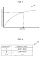
- FIG. 7 is a view showing an example of a permitted discharge power table 174 stored in the storage part 170.
- the permitted discharge power table 174 is a data table describing a correspondence relation between SOC of the battery pack 500 and permitted discharge power. Although a data format may be arbitrary, for convenience of explanation, here, the data example is shown in graph format. Values of the permitted discharge power table 174 are previously obtained by, for example, calculation, and can be stored in the storage part 170.
- the battery pack control part 140 uses the SOC of the battery pack 500 acquired by using the SOC table 171 and the permitted discharge power table 174 and can acquire the permitted discharge power of the battery pack 500.
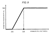
- FIG. 8 is a view showing an example of minimum CCV range data 175 stored in the storage part 170.
- the minimum CCV range data 175 is data describing a range of the minimum value of CCV of each of the single cells 510, within which the permitted power is restricted. The same value may be used for all the single cells 510, or different values may be used according to the characteristics of the respective single cells 510.
- the minimum CCV range data 175 is the data describing this range.
- the battery pack 500 When the battery pack 500 is discharged, it is presumed that a certain degree of charge is charged in each of the single cells 510. When a charge amount is insufficient, a desired discharge amount can not be obtained. Then, in the embodiment 2, the permitted range of the inter-terminal voltage of each of the single cells 510 is previously determined. When the inter-terminal voltage of the single cell 510 is close to the lower limit value of the range, discharge power is suppressed to be low, and when the inter-terminal voltage is close to the upper limit value, larger discharge power is permitted.
- FIG. 9 is a view showing a situation in which the battery control apparatus 100 of the embodiment 2 adjusts the permitted discharge power of the whole battery pack 500 in order to control the inter-terminal voltage of each of the single cells 510.
- the values described in the minimum CCV range data 175 are used for the permitted range of the inter-terminal voltage of each of the single cells 510.
- 2.6 V to 3.0 V exemplified in FIG. 8 was used.
- the inter-terminal voltage of the single cell 510 When the inter-terminal voltage of the single cell 510 is close to the lower limit value (2.6 V) of the permitted range, since large discharge power can not be permitted, the permitted discharge power is decreased. When the inter-terminal voltage of the single cell 510 is not larger than the lower limit value (2.6 V) of the permitted range, discharging of the battery pack 500 is not permitted.
- the inter-terminal voltage of the single cell 510 is close to the upper limit value (3.0 V), since larger discharge power can be permitted, the permitted discharge power is increased.
- the inter-terminal voltage of the single cell 510 is not lower than the upper limit value (3.0 V)
- 100% of the permitted discharge power obtained from the permitted discharge power table 174 is used.
- the inter-terminal voltages of the respective single cells 510 are different from one another, from the viewpoint of operation safety, it is desirable that a minimum one of the inter-terminal voltages of the single cells 510 is made a reference, and the permitted discharge power is obtained.
- step 1 to step 2 described in the embodiment 1.
- Step 3 Obtain permitted discharge power of the battery pack 500
- the battery pack control part 140 uses the SOC of the battery pack 500 acquired at step 2 and the permitted discharge power table 174 and acquires the permitted discharge power of the battery pack 500.
- Step 4 Acquire permitted power restricted range of CCV of the single cell 510)
- the battery pack control part 140 acquires the permitted power restricted range of CCV of the single cell 510 from the minimum CCV range data 175.
- Step 5 Obtain rate of restricting permitted discharge power
- the battery pack control part 140 acquires a degree of closeness of the CCV of the single cell 510 acquired at step 1 to the lower limit value of the permitted power restricted range acquired at step 4, and obtains the rate of restricting the permitted discharge power based on this.
- a method of obtaining the rate of restricting the permitted discharge power may be the same as that of the embodiment 1.
- the battery pack control part 140 restricts the permitted discharge power in accordance with the rate obtained at step 5.
- the battery pack control part 140 itself has the function to control the permitted discharge power, this may be performed by itself.
- a higher-level control apparatus for example, the vehicle control part 200
- the battery control apparatus 100 of the embodiment 2 restricts the permitted discharge power of the battery pack 500 in accordance with the degree of closeness of the CCV of the single cell 510 to the lower limit value of the permitted power restricted range.
- the discharge power is restricted before the inter-terminal voltage of the single cell 510 exceeds the permitted power restricted range, and an appropriate discharge amount can be obtained.
- the SOC of the battery pack 500 is obtained by using the SOC table 171 in the embodiments 1 to 2, this can be obtained by another method, for example, by use of a specified arithmetic expression.
- the permitted charge and discharge powers are obtained by using the permitted charge power table 172 and the permitted discharge power table 174 in the embodiments 1 to 2, these can be obtained by another method, for example, by use of a specified arithmetic expression.
- the above respective structures, functions and processing parts can be realized as hardware by designing all or part thereof with, for example, an integrated circuit, or can also be realized as software by a program executed by a processor to realize the respective functions.
- the program to realize the respective functions and the information such as the table can be stored in a storage device such as a memory or a hard disk or a storage medium such as an IC card or a DVD.
- 100 battery control apparatus, 110: single cell management part, 111: single cell control part, 112: voltage detection circuit, 113: control circuit, 114: signal input and output circuit, 120: current detection part, 130: voltage detection part, 140: battery pack control part, 150: signal communication unit, 160: insulation element, 170: storage part, 171: SOC table, 172: permitted charge power table, 173: maximum CCV range data, 174: permitted discharge power table, 175: minimum CCV range data, 200: vehicle control part, 300 and 310: relay, 400: invertor, 410: motor generator, 500: battery pack, 510: single cell, 520: single cell group.
Landscapes
- Engineering & Computer Science (AREA)
- Power Engineering (AREA)
- Life Sciences & Earth Sciences (AREA)
- Sustainable Development (AREA)
- Sustainable Energy (AREA)
- Transportation (AREA)
- Mechanical Engineering (AREA)
- Chemical Kinetics & Catalysis (AREA)
- Manufacturing & Machinery (AREA)
- Chemical & Material Sciences (AREA)
- Electrochemistry (AREA)
- General Chemical & Material Sciences (AREA)
- Microelectronics & Electronic Packaging (AREA)
- General Physics & Mathematics (AREA)
- Physics & Mathematics (AREA)
- Charge And Discharge Circuits For Batteries Or The Like (AREA)
- Secondary Cells (AREA)
Abstract
Description
- The present invention relates to an apparatus for controlling a battery.
- A vehicle running by using electricity as driving force is mounted with a storage battery such as a lead-acid battery, a nickel hydrogen battery or a lithium ion battery. The electric power required when a hybrid vehicle or an electric vehicle runs is supplied by the storage battery.
- The permitted charge power and discharge power of the storage battery respectively vary according to the state of charge. If charging or discharging over the maximum permitted power is performed, overcharging or overdischarging can occur. As the state of charge (SOC) of the storage battery becomes high, the maximum permitted charge power decreases and the maximum permitted discharge power increases. Besides, as the SOC of the storage battery becomes low, the maximum permitted discharge power decreases and the permitted charge power increases. In order to safely use the storage battery, the charging and discharging control is required to be performed within a range not exceeding the maximum permitted power.
-
PTL 1 mentioned below discloses a technique in which even when a temperature variation occurs among single cells constituting a battery pack, permitted charge and discharge powers suitable for respective single cells are calculated, and charging and discharging control is optimally performed. -
PTL 2 mentioned below discloses a method in which a maximum cell voltage value and a minimum cell voltage value are detected, maximum charge power is determined by using the maximum cell voltage value, and maximum discharge power is determined by using the minimum cell voltage value. -
- PTL 1:
JP-A-2007-165211 - PTL 22:
JP-A-2004-266917 - In the technique disclosed in
Patent Literature 1, the permitted charge and discharge powers are obtained at each of the highest temperature Tmax and the lowest temperature Tmin of the storage battery 10, and smaller values are used. In this method, since the position where the temperature sensor is disposed does not necessarily correspond to each of the single cells, there is a possibility that the temperature detected by the temperature sensor does not necessarily accurately correspond to the permitted charge and discharge powers of each of the single cells. Accordingly, there is a possibility that the inter-terminal voltage of each of the single cells exceeds the permitted range. - Besides,
Patent Literature 1 discloses that the state of charge of each single cell is acquired, and the charging and discharging management is performed in view of variation in the state of charge of the single cell. However, the control process for managing the state of charge of each single cell becomes complicated, and the cost can become high. The technique disclosed inPatent Literature 2 has also the same problems. - The invention is made in order to solve the foregoing problem, and has an object to provide a battery control apparatus which can keep an inter-terminal voltage of each single cell within a permitted range while permitted power is controlled in units of a battery pack.
- The battery control apparatus of the invention restricts permitted power of a battery pack according to a degree of closeness of a close circuit voltage (CCV) of a single cell to an upper limit or a lower limit of a permitted range.
- According to the battery control apparatus of the invention, when the CCV of the single cell approaches the upper limit or the lower limit of the permitted range, permitted power is suppressed to prevent exceeding this, so that the single cell can be protected. Besides, since the permitted power of the battery pack is directly controlled, the control is performed in units of a battery pack, and the load of the control process can be reduced.
-
- [
FIG. 1] FIG. 1 is a view showing abattery control apparatus 100 ofembodiment 1 and its peripheral circuit structure. - [
FIG. 2] FIG. 2 is a view showing a circuit structure of a singlecell control part 111. - [
FIG. 3] FIG. 3 is a view showing an example of an SOC table 171 stored in astorage part 170. - [
FIG. 4] FIG. 4 is a view showing an example of a permitted charge power table 172 stored in thestorage part 170. - [
FIG. 5] FIG. 5 is a view showing an example of a maximum CCV range data stored in thestorage part 170. - [
FIG. 6] FIG. 6 is a view showing a situation in which thebattery control apparatus 100 ofembodiment 1 adjusts permitted charge power of thewhole battery pack 500 in order to control inter-terminal voltage of eachsingle cell 510. - [
FIG. 7] FIG. 7 is a view showing an example of a permitted discharge power table 174 stored in astorage part 170 inembodiment 2. - [
FIG. 8] FIG. 7 is a view showing an example of minimumCCV range data 175 stored in thestorage part 170 inembodiment 2. - [
FIG. 9] FIG. 9 is a view showing a situation in which abattery control apparatus 100 ofembodiment 2 adjusts permitted discharge power of thewhole battery pack 500 in order to control inter-terminal voltage of eachsingle cell 510. - In embodiments described below, although a battery pack is constructed by connecting single cells in series, the battery pack may be constructed by connecting parallel-connected single cells in parallel, or may be constructed by connecting series-connected single cells in parallel.
-
FIG. 1 is a view showing abattery control apparatus 100 ofembodiment 1 of the invention and its peripheral circuit structure. Thebattery control apparatus 100 is an apparatus to monitor and control the state of abattery pack 500. Thebattery control apparatus 100 includes a singlecell management part 110, acurrent detection part 120, avoltage detection part 130, a batterypack control part 140 and astorage part 170. - The
battery pack 500 is constructed such that pluralsingle cells 510 each of which can store and discharge electric energy (charging and discharging of DC power) are electrically connected in series. Thesingle cells 510 constituting thebattery pack 500 are grouped by a specified number of units for execution of state management and control. The groupedsingle cells 510 are electrically connected in series, and constitutesingle cell groups single cells 510 constituting thesingle cell group 520 may be the same in all thesingle cell groups 520, or the number ofsingle cells 510 may be different among thesingle cell groups 520. - The single
cell management part 110 monitors the states of thesingle cells 510 constituting thebattery pack 500. The singlecell management part 110 includes a singlecell control part 111 provided for each of thesingle cell groups 520. InFIG. 1 , the singlecell control parts single cell groups cell control part 111 monitors and controls the states of thesingle cells 510 constituting thesingle cell group 520. - In the
embodiment 1, for simplifying the explanation, the foursingle cells 510 are electrically connected in series to constitute each of thesingle cell groups single cell groups battery pack 500 includes the eightsingle cells 510 in total. - The battery
pack control part 140 and the singlecell management part 110 transmit and receive signals throughinsulation elements 160 typified by a photocoupler andsignal communication units 150. - A communication unit between the battery
pack control part 140 and the singlecell control parts cell management part 110 will be described. The singlecell control parts single cell groups pack control part 140 to the singlecell management part 110 is inputted to the singlecell control part 111a through theinsulation element 160 and thesignal communication unit 150. The output of the singlecell control part 111a is inputted to the singlecell control part 111b through thesignal communication unit 150. The output of the lowest-level singlecell control part 111b is transmitted to the batterypack control part 140 through theinsulation element 160 and thesignal communication unit 150. In theembodiment 1, although theinsulation element 160 does not intervene between the singlecell control part 111a and the singlecell control part 111b, a signal can also be transmitted and received through theinsulation element 160. - The battery
pack control part 140 performs the state detection of thesingle cell 510, thesingle cell group 520 or thebattery pack 500 based on the information transmitted by the singlecell management part 110, the current value inputted to and outputted from thebattery pack 500, which is transmitted by thecurrent detection part 120, the total voltage value of thebattery pack 500 transmitted by thevoltage detection part 130, the information previously stored in thestorage part 170, and the like. - The information outputted by the single
cell management part 110 to the batterypack control part 140 includes the measurement value of the voltage and temperature of thesingle cell 510, and abnormal information of thesingle cell 510 such as overcharging, overdischarging or over temperature of thesingle cell 510. Further, the singlecell management part 110 may output also a communication error of the singlecell management part 110 itself or the singlecell control part 111, and an abnormal signal in the case of physical failure typified by breaking of a harness to the batterypack control part 140. In this case, the batterypack control part 140 can perform the charging and discharging control of thebattery pack 500 in view of the abnormal contents of the singlecell management part 110 or the singlecell control part 111. - The information stored in the
storage part 170 includes internal resistance characteristics of thebattery pack 500, thesingle cell 510 and thesingle cell group 520, capacity at full charge, polarization voltage, deterioration characteristics, individual difference information, and correspondence relation between SOC and open circuit voltage (OCV). Further, characteristic information of the singlecell management part 110, the singlecell control part 111, the batterypack control part 140 and the like can also be previously stored. The information stored in thestorage part 170 will be again described with reference to after-mentionedFIG. 3 to FIG. 5 . - The battery
pack control part 140 carries out an operation required to manage SOC of at least onesingle cell 510, state of health (SOH), current and power capable of being inputted and outputted, abnormal state, SOC of thesingle cell 510 and the like based on the measurement values and the information stored in thestorage part 170. Then, based on the operation result, information is outputted to the singlecell management part 110 and avehicle control part 200. - The
vehicle control part 200 is a control apparatus superordinate to the batterypack control part 140, and connects thebattery control apparatus 100 and aninvertor 400 throughrelays pack control part 140. Thevehicle control part 200 can issue an instruction to the batterypack control part 140 when necessary, and the batterypack control part 140 may start the process based on the instruction from thevehicle control part 200. - When a vehicle system mounted with the
battery control apparatus 100 starts and runs, thebattery control apparatus 100 is connected to theinvertor 400 under management of thevehicle control part 200, and drives amotor generator 410 by using energy stored in thebattery pack 500. At the time of regeneration, thebattery pack 500 is charged by power generated by themotor generator 410. -
FIG. 2 is a view showing a circuit structure of the singlecell control part 111. The singlecell control part 111 includes a voltage detection circuit 112, acontrol circuit 113 and a signal input andoutput circuit 114. The voltage detection circuit 112 measures the inter-terminal voltage of each of thesingle cells 510. Thecontrol circuit 113 receives the measurement result from the voltage detection circuit 112, and transmits it to the batterypack control part 140 through the signal input andoutput circuit 114. Besides, the control circuit controls a charging operation and a discharging operation of each of thesingle cells 510. Since a circuit structure of the charging operation and the discharging operation is well known, its description is omitted. -
FIG. 3 is a view showing an example of an SOC table 171 stored in thestorage part 170. The SOC table 171 is a data table describing a correspondence relation between OCV of thebattery pack 500 and SOC of thebattery pack 500. Although the data format may be arbitrary, for convenience of explanation, here, the data example is shown in graph format. - The OCV is a voltage at the time of no load of the
battery pack 500. The OCV can be acquired when the inter-terminal voltage of thesingle cell 510 is acquired at the timing before therelays battery pack 500 is not started although therelays pack control part 140 integrates the OCV of thesingle cell 510 detected by the singlecell control part 111 to obtain the OCV of thebattery pack 500, and can obtain the SOC of thebattery pack 500 by using the OCV of thebattery pack 500 and the SOC table 171. Further, during the charging and discharging of thebattery pack 500, the OCV is obtained by removing an internal resistance component and a polarization voltage component from the CCV, and the SOC of thebattery pack 500 can be similarly obtained. -
FIG. 4 is a view showing an example of a permitted charge power table 172 stored in thestorage part 170. The permitted charge power table 172 is a data table describing a correspondence relation between the SOC of thebattery pack 500 and the permitted charge power. Although the data format may be arbitrary, for convenience of explanation, here, the data example is shown in graph format. Values of the permitted charge power table 172 are previously obtained by, for example, calculation and can be stored in thestorage part 170. - The battery
pack control part 140 can acquire the permitted charge power of thebattery pack 500 by using the SOC of thebattery pack 500 acquired by using the SOC table 171 and the permitted charge power table 172. -
FIG. 5 is a view showing an example of maximumCCV range data 173 stored in thestorage part 170. The maximumCCV range data 173 is data describing a range of the maximum value of CCV of each of thesingle cells 510, within which the permitted power is restricted. The same value may be used for all thesingle cells 510, or different values may be used according to the characteristic of each of thesingle cells 510. - When the
battery pack 500 is charged, there is an upper limit for permitted charge power. Correspondingly to this, a range of maximum CCV of thesingle cell 510 is set within which the permitted power is restricted. The maximumCCV range data 173 is the data describing this range. - In the above, the structure of the
battery control apparatus 100 is described. Next, with respect to the operation of thebattery control apparatus 100, a basic concept and an operation procedure will be described. - Even when the
whole battery pack 500 operates within the range of rated voltage, each of thesingle cells 510 can exceed the rated voltage. When thebattery pack 500 is charged, in order to keep the inter-terminal voltage of each of the single cells within the rated voltage, the charge power to each of thesingle cells 510 is required to be individually controlled, or the permitted charge power of thewhole battery pack 500 is suppressed to be sufficiently low so that the inter-terminal voltage of each of thesingle cells 510 falls within the rated voltage. - With respect to the method of individually controlling the charge power to each of the
single cells 510, such a problem is conceivable that the control process becomes complicated and the cost becomes high. Thus, in theembodiment 1, an attempt is made to keep the inter-terminal voltage of each of thesingle cells 510 within the rated voltage by suppressing the permitted charge power of thewhole battery pack 500 to be sufficiently low. - Specifically, a range of the inter-terminal voltage of each of the
single cells 510 is previously determined within which the permitted power is restricted. When the inter-terminal voltage of thesingle cell 510 is close to the lower limit value of this range, a larger charge power is permitted, and when the inter-terminal voltage is close to the upper limit value, the charge power is suppressed to be low. -
FIG. 6 is a view showing a situation in which thebattery control apparatus 100 of theembodiment 1 adjusts the permitted charge power of thewhole battery pack 500 in order to control the inter-terminal voltage of each of thesingle cells 510. The values described in the maximumCCV range data 173 are used for the range of the inter-terminal voltage of each of thesingle cells 510, within which the permitted power is restricted. Here, 4.0 V to 4.4 V exemplified inFIG. 5 was used. - When the inter-terminal voltage of the
single cell 510 is close to the lower limit value (4.0 V) of the range within which the permitted power is restricted, a larger charge power can be permitted. Accordingly, the permitted charge power is increased. When the inter-terminal voltage of thesingle cell 510 is coincident with the lower limit value (4.0 V) of the permitted range, 100% of the permitted charge power obtained from the permitted charge power table 172 is used. - On the other hand, when the inter-terminal voltage of the
single cell 510 is close to the upper limit value (4.4 V) of the range within which the permitted power is restricted, a large charge power can not be permitted. Accordingly, the permitted charge power is decreased. When the inter-terminal voltage of thesingle cell 510 is coincident with the upper limit value (4.4 V) of the permitted range, the supply of the charge power to thesingle cell 510 is not permitted. - The above relation is shown in graph as in
FIG. 6 . That is, the case where the inter-terminal voltage of thesingle cell 510 is coincident with the lower limit value (4.0 V) of the range of restricting the permitted power is made 100%. As the inter-terminal voltage of thesingle cell 510 approaches the upper limit value (4.4 V) of the range of restricting the permitted power, the permitted charge power is decreased. In the section between the lower limit value (4.0 V) and the upper limit value (4.4 V) of the permitted range, for example, linear interpolation may be performed by proportional calculation, or the permitted charge power in the section may be described in data such as the maximumCCV range data 173. - Incidentally, when the inter-terminal voltages of the respective
single cells 510 are different from one another other, from the viewpoint of operation safety, it is desirable that a maximum one of the inter-terminal voltages of the respectivesingle cells 510 is made a reference, and the permitted charge power is obtained. - In the following, a description will be made on an operation procedure of keeping the inter-terminal voltage of each of the
single cells 510 within the range described in the maximumCCV range data 173 when thebattery control apparatus 100 causes thebattery pack 500 to be charged. - The battery
pack control part 140 instructs the singlecell management part 110 to acquire the CCV of thesingle cell 510. The singlecell control part 111 acquires the detection result of the voltage detection circuit 112, and outputs the detection result to the batterypack control part 140. The batterypack control part 140 acquires the CCV of thewhole battery pack 500 from thevoltage detection part 130. - When the CCV of the
single cell 510 is acquired at this step, a maximum one of the CCVs of the respectivesingle cells 510 may be acquired from the viewpoint of operation safety. - The battery
pack control part 140 uses the OCV calculated from the CCV of thebattery pack 500 acquired atstep 1 and the SOC table 171, and acquires the SOC of thebattery pack 500. - The battery
pack control part 140 uses the SOC of thebattery pack 500 acquired atstep 2 and the permitted charge power table 172, and acquires the permitted charge power of thebattery pack 500. - The battery
pack control part 140 acquires the permitted power restricted range of the CCV of thesingle cell 510 from the maximumCCV range data 173. When the permitted power restricted ranges of the CCVs of the respectivesingle cells 510 are not equal to each other, the permitted power restricted range of the CCV of the single cell having the lowest rated voltage may be selected for safety. - The battery
pack control part 140 acquires a degree of closeness of the CCV of thesingle cell 510 acquired atstep 1 to the upper limit value of the permitted power restricted range acquired at step 4, and obtains the rate of restricting the permitted charge power based on this. As a method of obtaining the rate of restricting the permitted charge power, following examples are conceivable. - It is assumed that the CCV of the
single cell 510 is 4.2 V, and the permitted power restricted range of the CCV is 4.0 V to 4.4 V. When the linear interpolation as exemplified inFIG. 6 is used, it is understood that the permitted charge power should be suppressed to 50%. - It is assumed that the permitted power restricted range of the CCV is 4.0 to 4.4 V. When the CCV of the
single cell 510 is the center value (4.2 V) or higher, the permitted amount is decreased (permitted rate = 30%), and when the OCV of thesingle cell 510 is less than the center value (4.2 V), the permitted amount is increased (permitted rate = 80%). - When the CCV of the
single cell 510 acquired atstep 1 is lower than the lower limit value of the permitted power restricted range acquired at step 4, charging may be performed at the maximum charge power (permitted rate = 100%). - When the CCV of the
single cell 510 acquired atstep 1 is higher than the upper limit value of the permitted power restricted range acquired at step 4, charging may not be permitted (permitted rate = 0%), or an alarm may be given to a higher-level control apparatus (for example, the vehicle control part 200). - The battery
pack control part 140 restricts the permitted charge power in accordance with the rate obtained at step 5. When the batterypack control part 140 itself has the function to limit the permitted charge power, this may performed by itself. Alternatively, a higher-level control apparatus (for example, the vehicle control part 200) may be notified to restrict the permitted charge power. - As described above, the
battery control apparatus 100 of theembodiment 1 restricts the permitted charge power of thebattery pack 500 according to the degree of closeness of the CCV of thesingle cell 510 to the upper limit of the permitted power restricted range. By this, the charge power is restricted before the inter-terminal voltage of thesingle cell 510 exceeds the permitted range and thesingle cell 510 can be protected. - Besides, the
battery control apparatus 100 of theembodiment 1 performs the control process to keep the inter-terminal voltage of thesingle cell 510 within the permitted range in units of thebattery pack 500. By this, since the control process can be simplified, this is advantageous from the viewpoint of calculation load and the like. - In the
embodiment 1, the example is described in which thesingle cell 510 is protected by restricting the permitted charge power. The same method can be used also in an operation at the time of discharging. Then, inembodiment 2 of the invention, a method of restricting permitted discharge power will be described. Since a structure of abattery control apparatus 100 and its peripheral circuit is substantially the same as that of theembodiment 1, different points will be mainly described below. -
FIG. 7 is a view showing an example of a permitted discharge power table 174 stored in thestorage part 170. The permitted discharge power table 174 is a data table describing a correspondence relation between SOC of thebattery pack 500 and permitted discharge power. Although a data format may be arbitrary, for convenience of explanation, here, the data example is shown in graph format. Values of the permitted discharge power table 174 are previously obtained by, for example, calculation, and can be stored in thestorage part 170. - The battery
pack control part 140 uses the SOC of thebattery pack 500 acquired by using the SOC table 171 and the permitted discharge power table 174 and can acquire the permitted discharge power of thebattery pack 500. -
FIG. 8 is a view showing an example of minimumCCV range data 175 stored in thestorage part 170. The minimumCCV range data 175 is data describing a range of the minimum value of CCV of each of thesingle cells 510, within which the permitted power is restricted. The same value may be used for all thesingle cells 510, or different values may be used according to the characteristics of the respectivesingle cells 510. - When the
battery pack 500 is discharged, there is a lower limit of permitted discharge power. Correspondingly to this, a range of minimum CCV of thesingle cell 510 is set within which the permitted power is restricted. The minimumCCV range data 175 is the data describing this range. - In the above, the structure of the
battery control apparatus 100 is described. Next, with respect to the operation of thebattery control apparatus 100, a basic concept and an operation procedure will be described. - When the
battery pack 500 is discharged, it is presumed that a certain degree of charge is charged in each of thesingle cells 510. When a charge amount is insufficient, a desired discharge amount can not be obtained. Then, in theembodiment 2, the permitted range of the inter-terminal voltage of each of thesingle cells 510 is previously determined. When the inter-terminal voltage of thesingle cell 510 is close to the lower limit value of the range, discharge power is suppressed to be low, and when the inter-terminal voltage is close to the upper limit value, larger discharge power is permitted. -
FIG. 9 is a view showing a situation in which thebattery control apparatus 100 of theembodiment 2 adjusts the permitted discharge power of thewhole battery pack 500 in order to control the inter-terminal voltage of each of thesingle cells 510. The values described in the minimumCCV range data 175 are used for the permitted range of the inter-terminal voltage of each of thesingle cells 510. Here, 2.6 V to 3.0 V exemplified inFIG. 8 was used. - When the inter-terminal voltage of the
single cell 510 is close to the lower limit value (2.6 V) of the permitted range, since large discharge power can not be permitted, the permitted discharge power is decreased. When the inter-terminal voltage of thesingle cell 510 is not larger than the lower limit value (2.6 V) of the permitted range, discharging of thebattery pack 500 is not permitted. - On the other hand, when the inter-terminal voltage of the
single cell 510 is close to the upper limit value (3.0 V), since larger discharge power can be permitted, the permitted discharge power is increased. When the inter-terminal voltage of thesingle cell 510 is not lower than the upper limit value (3.0 V), 100% of the permitted discharge power obtained from the permitted discharge power table 174 is used. - The above relation is shown in graph as in
FIG. 9 . That is, the case where the inter-terminal voltage of thesingle cell 510 is coincident with the upper limit value (3.0 V) of the permitted range is made 100%. As the inter-terminal voltage of thesingle cell 510 approaches the lower limit value (2.6 V) of the permitted range, the permitted discharge power is decreased. In the section between the lower limit value (2.6 V) and the upper limit value (3.0 V) of the permitted range, for example, linear interpolation may be performed by proportional calculation, or the permitted discharge power in the section may be described in data such as the minimumCCV range data 175. - Incidentally, when the inter-terminal voltages of the respective
single cells 510 are different from one another, from the viewpoint of operation safety, it is desirable that a minimum one of the inter-terminal voltages of thesingle cells 510 is made a reference, and the permitted discharge power is obtained. - In the following, a description will be made on an operation procedure to keep the inter-terminal voltage of the
single cell 510 within the range described in the minimumCCV range data 175 when thebattery control apparatus 100 causes thebattery pack 500 to be discharged. - These steps are the same as
step 1 to step 2 described in theembodiment 1. - The battery
pack control part 140 uses the SOC of thebattery pack 500 acquired atstep 2 and the permitted discharge power table 174 and acquires the permitted discharge power of thebattery pack 500. - The battery
pack control part 140 acquires the permitted power restricted range of CCV of thesingle cell 510 from the minimumCCV range data 175. - The battery
pack control part 140 acquires a degree of closeness of the CCV of thesingle cell 510 acquired atstep 1 to the lower limit value of the permitted power restricted range acquired at step 4, and obtains the rate of restricting the permitted discharge power based on this. A method of obtaining the rate of restricting the permitted discharge power may be the same as that of theembodiment 1. - When the CCV of the
single cell 510 acquired atstep 1 is higher than the upper limit value of the permitted power restricted range acquired at step 4, discharging may be performed at the maximum discharge power (permitted rate = 100%). - When the CCV of the
single cell 510 acquired atstep 1 is lower than the lower limit value of the permitted power restricted range acquired at step 4, discharging may not be permitted to be performed (permitted rate = 0%), or an alarm may be given to a higher-level control apparatus (for example, the vehicle control part 200). - The battery
pack control part 140 restricts the permitted discharge power in accordance with the rate obtained at step 5. When the batterypack control part 140 itself has the function to control the permitted discharge power, this may be performed by itself. Alternatively, a higher-level control apparatus (for example, the vehicle control part 200) may be notified to restrict the permitted charge power. - As described above, the
battery control apparatus 100 of theembodiment 2 restricts the permitted discharge power of thebattery pack 500 in accordance with the degree of closeness of the CCV of thesingle cell 510 to the lower limit value of the permitted power restricted range. By this, the discharge power is restricted before the inter-terminal voltage of thesingle cell 510 exceeds the permitted power restricted range, and an appropriate discharge amount can be obtained. - Incidentally, it is needless to say that the charge control method described in the
embodiment 1 and the discharge control method described in theembodiment 2 are combined, and the optimum control can be performed both at the time of charge and discharge. - Although the SOC of the
battery pack 500 is obtained by using the SOC table 171 in theembodiments 1 to 2, this can be obtained by another method, for example, by use of a specified arithmetic expression. Similarly, although the permitted charge and discharge powers are obtained by using the permitted charge power table 172 and the permitted discharge power table 174 in theembodiments 1 to 2, these can be obtained by another method, for example, by use of a specified arithmetic expression. - In the above, although the invention made by the inventor is specifically described based on the embodiments, it is needless to say that the invention is not limited to the embodiments, and various modifications can be made in the range not departing from the gist.
- Besides, the above respective structures, functions and processing parts can be realized as hardware by designing all or part thereof with, for example, an integrated circuit, or can also be realized as software by a program executed by a processor to realize the respective functions. The program to realize the respective functions and the information such as the table can be stored in a storage device such as a memory or a hard disk or a storage medium such as an IC card or a DVD.
- 100: battery control apparatus, 110: single cell management part, 111: single cell control part, 112: voltage detection circuit, 113: control circuit, 114: signal input and output circuit, 120: current detection part, 130: voltage detection part, 140: battery pack control part, 150: signal communication unit, 160: insulation element, 170: storage part, 171: SOC table, 172: permitted charge power table, 173: maximum CCV range data, 174: permitted discharge power table, 175: minimum CCV range data, 200: vehicle control part, 300 and 310: relay, 400: invertor, 410: motor generator, 500: battery pack, 510: single cell, 520: single cell group.
Claims (12)
- A battery control apparatus comprising:a control part to control a battery pack in which a plurality of single cells are connected;a voltage measurement part to measure an inter-terminal voltage of the single cell and an inter-terminal voltage of the battery pack; anda storage part to store cell voltage data of a permitted power restricted range describing a range of a close circuit voltage of the single cell within which a permitted power is restricted, whereinthe control partacquires the close circuit voltage of the single cell and the close circuit voltage of the battery pack measured by the voltage measurement part,acquires a present permitted power of the battery pack by using the close circuit voltage of the battery pack,calculates a rate of restricting the permitted power of the battery pack in accordance with a degree of closeness of the close circuit voltage of the single cell to an upper limit value or a lower limit value of the range described in the permitted cell voltage data, andrestricts the permitted power of the battery pack in accordance with the rate.
- The battery control apparatus according to claim 1, wherein
the permitted cell voltage data describes the permitted range of the close circuit voltage of the single cell when the battery pack is charged,
and when the battery pack is charged, the control partsets the rate not to permit the battery pack to be charged when the close circuit voltage of the single cell is equal to the upper limit value of the range,sets the rate to cause the battery pack to be charged at a maximum value of permitted charge power of the battery pack when the close circuit voltage of the single cell is equal to the lower limit value of the range, andsets, as the rate, a value between the rate of the case where the close circuit voltage of the single cell is equal to the upper limit value of the range and the rate of the case where the close circuit voltage of the single cell is equal to the lower limit value of the range when the close circuit voltage of the single cell is between the upper limit value and the lower limit value of the range. - The battery control apparatus according to claim 2, wherein
the control part sets the rate to cause the battery pack to be charged at the maximum value of the permitted charge power of the battery pack when the close circuit voltage of the single cell is lower than the lower limit value of the range. - The battery control apparatus according to claim 2, wherein the control part sets the rate not to permit the battery pack to be charged when the close circuit voltage of the single cell is higher than the upper limit value of the range.
- The battery control apparatus according to claim 2, wherein the control part gives an alarm when the close circuit voltage of the single cell is higher than the upper limit value.
- The battery control apparatus according to claim 1, wherein
the permitted cell voltage data describes the permitted range of the close circuit voltage of the single cell when the battery pack is discharged,
and when the battery pack is discharged, the control partsets the rate to cause the battery pack to be discharged at a maximum value of permitted discharge power of the battery pack when the close circuit voltage of the single cell is equal to the upper limit value,sets the rate not to permit the battery pack to be discharged when the close circuit voltage of the single cell is equal to the lower limit value of the range, andsets, as the rate, a value between the rate of the case where the close circuit voltage of the single cell is equal to the upper limit value of the range and the rate of the case where the close circuit voltage of the single cell is equal to the lower limit value of the range when the close circuit voltage of the single cell is between the upper limit value and the lower limit value of the range. - The battery control apparatus according to claim 6, wherein the control part sets the rate to cause the battery pack to be discharged at the maximum value of the permitted discharge power of the battery pack when the close circuit voltage of the single cell is higher than the upper limit value of the range.
- The battery control apparatus according to claim 6, wherein the control part sets the rate not to permit the battery pack to be discharged when the close circuit voltage of the single cell is lower than the lower limit value of the range.
- The battery control apparatus according to claim 6, wherein the control parts gives an alarm when the close circuit voltage of the single cell is lower than the lower limit value of the range.
- The battery control apparatus according to claim 1, wherein
when the close circuit voltage of the single cell is between the upper limit value and the lower limit value of the range,
the control part calculates a value between the rate of the case where the close circuit voltage of the single cell is equal to the upper limit value and the rate of the case where the close circuit voltage of the single cell is equal to the lower limit value of the range by proportional calculation, and sets the thus obtained value as the rate. - The battery control apparatus according to claim 1, wherein
the permitted cell voltage data describes a correspondence relation between the close circuit voltage of the single cell and the rate,
and when the close circuit voltage of the single cell is between the upper limit value and the lower limit value of the range,
the control part sets the rate in accordance with the correspondence relation between the close circuit voltage of the single cell and the rate, which is described in the permitted cell voltage data. - The battery control apparatus according to claim 1, wherein
the storage part storesan SOC table describing a corresponding relation between an open circuit voltage of the battery pack and a state of charge, anda permitted power table describing a correspondence relation between the state of charge of the battery pack and the permitted power, andthe control partacquires a present state of charge of the battery pack by using the close circuit voltage of the battery pack and the SOC table, andacquires the present permitted power of the battery pack by using the state of charge of the battery pack and the permitted power table.
Applications Claiming Priority (1)
| Application Number | Priority Date | Filing Date | Title |
|---|---|---|---|
| PCT/JP2011/061190 WO2012157065A1 (en) | 2011-05-16 | 2011-05-16 | Battery control device |
Publications (3)
| Publication Number | Publication Date |
|---|---|
| EP2712046A1 true EP2712046A1 (en) | 2014-03-26 |
| EP2712046A4 EP2712046A4 (en) | 2016-05-18 |
| EP2712046B1 EP2712046B1 (en) | 2019-07-17 |
Family
ID=47176434
Family Applications (1)
| Application Number | Title | Priority Date | Filing Date |
|---|---|---|---|
| EP11865666.9A Active EP2712046B1 (en) | 2011-05-16 | 2011-05-16 | Battery control device |
Country Status (5)
| Country | Link |
|---|---|
| US (1) | US9680320B2 (en) |
| EP (1) | EP2712046B1 (en) |
| JP (1) | JP5670556B2 (en) |
| CN (1) | CN103534897B (en) |
| WO (1) | WO2012157065A1 (en) |
Cited By (4)
| Publication number | Priority date | Publication date | Assignee | Title |
|---|---|---|---|---|
| WO2014160759A3 (en) * | 2013-03-29 | 2015-04-23 | Fca Us Llc | Techniques for enhanced battery pack recharging |
| EP3323667A1 (en) * | 2016-11-17 | 2018-05-23 | MAN Truck & Bus AG | Traction energy storage system with identification of operating limits |
| WO2020205165A1 (en) * | 2019-04-05 | 2020-10-08 | Oshkosh Corporation | Battery management systems and methods |
| WO2021178881A1 (en) * | 2020-03-06 | 2021-09-10 | Oshkosh Corporation | Battery monitoring system for a lift device |
Families Citing this family (11)
| Publication number | Priority date | Publication date | Assignee | Title |
|---|---|---|---|---|
| WO2012157065A1 (en) * | 2011-05-16 | 2012-11-22 | 日立ビークルエナジー株式会社 | Battery control device |
| JP2012247339A (en) * | 2011-05-30 | 2012-12-13 | Renesas Electronics Corp | Semiconductor integrated circuit and operation method therefor |
| KR101509895B1 (en) * | 2013-06-28 | 2015-04-06 | 현대자동차주식회사 | Method for limiting power of battery |
| WO2015186327A1 (en) * | 2014-06-06 | 2015-12-10 | パナソニックIpマネジメント株式会社 | Electricity storage device and power supply device |
| WO2016140152A1 (en) * | 2015-03-02 | 2016-09-09 | 日立オートモティブシステムズ株式会社 | Battery control device and vehicle system |
| US10663529B1 (en) * | 2015-09-25 | 2020-05-26 | Amazon Technologies, Inc. | Automatic battery charging |
| JP6615011B2 (en) * | 2016-03-09 | 2019-12-04 | 日立オートモティブシステムズ株式会社 | Battery management system, battery system and hybrid vehicle control system |
| JP7192581B2 (en) * | 2019-03-11 | 2022-12-20 | 株式会社豊田自動織機 | Voltage measurement method |
| FR3098922B1 (en) * | 2019-07-18 | 2021-07-23 | Commissariat Energie Atomique | Method for determining the state of charge of the cells of a battery |
| US20240405299A1 (en) * | 2022-03-30 | 2024-12-05 | Vehicle Energy Japan Inc. | Battery control device and battery control method |
| WO2026062787A1 (en) | 2024-09-18 | 2026-03-26 | ビークルエナジージャパン株式会社 | Battery control system |
Family Cites Families (22)
| Publication number | Priority date | Publication date | Assignee | Title |
|---|---|---|---|---|
| JP3360613B2 (en) * | 1998-06-25 | 2002-12-24 | トヨタ自動車株式会社 | Battery control device |
| US6456042B1 (en) * | 2000-11-27 | 2002-09-24 | Delphi Technologies, Inc. | Method and apparatus for charging batteries at reduced overcharge levels |
| US6366054B1 (en) * | 2001-05-02 | 2002-04-02 | Honeywell International Inc. | Method for determining state of charge of a battery by measuring its open circuit voltage |
| DE10321720A1 (en) * | 2002-05-14 | 2003-12-04 | Yazaki Corp | Process to estimate the charge condition open circuit voltage and degree of degradation of a battery, involves comparing total electricity quantity with initial state |
| JP4035777B2 (en) * | 2003-02-10 | 2008-01-23 | 株式会社デンソー | Discharge device for battery pack |
| JP3908679B2 (en) | 2003-02-28 | 2007-04-25 | 株式会社神戸製鋼所 | Power control device for hybrid drive construction machine |
| US20050048335A1 (en) * | 2003-08-26 | 2005-03-03 | Fields Robert E. | Apparatus and method for regulating hybrid fuel cell power system output |
| US7683579B2 (en) * | 2005-06-14 | 2010-03-23 | Lg Chem, Ltd. | Method and apparatus of controlling for charge/discharge power of battery |
| JP5089883B2 (en) * | 2005-12-16 | 2012-12-05 | 日立ビークルエナジー株式会社 | Battery management device |
| JP4773848B2 (en) * | 2006-03-03 | 2011-09-14 | プライムアースEvエナジー株式会社 | Secondary battery charge / discharge control system, battery control device, and program |
| JP4560501B2 (en) * | 2006-08-11 | 2010-10-13 | 矢崎総業株式会社 | Charge state adjustment device |
| FR2907272B1 (en) * | 2006-10-13 | 2008-12-26 | Commissariat Energie Atomique | METHOD FOR MANAGING THE END OF DISCHARGE OF A RECHARGEABLE BATTERY |
| JP4484858B2 (en) * | 2006-10-19 | 2010-06-16 | 日立ビークルエナジー株式会社 | Storage battery management device and vehicle control device including the same |
| EP2120310B1 (en) * | 2007-03-07 | 2015-01-21 | Toyota Jidosha Kabushiki Kaisha | Secondary battery control device and vehicle |
| JP4987581B2 (en) * | 2007-06-15 | 2012-07-25 | 日立ビークルエナジー株式会社 | Battery control device |
| JP4893653B2 (en) * | 2008-02-19 | 2012-03-07 | トヨタ自動車株式会社 | Vehicle, rechargeable battery state of charge estimation method and vehicle control method |
| JP4551942B2 (en) * | 2008-03-14 | 2010-09-29 | 本田技研工業株式会社 | Hybrid DC power supply system, fuel cell vehicle, and storage device protection method |
| JP5092903B2 (en) * | 2008-05-29 | 2012-12-05 | トヨタ自動車株式会社 | Vehicle battery charge / discharge control device |
| JP5301657B2 (en) * | 2009-03-27 | 2013-09-25 | 株式会社日立製作所 | Power storage device |
| US8330420B2 (en) * | 2009-04-10 | 2012-12-11 | The Regents Of The University Of Michigan | Dynamically reconfigurable framework for a large-scale battery system |
| JP5516588B2 (en) * | 2009-09-03 | 2014-06-11 | トヨタ自動車株式会社 | Charged state detection device and charged state detection method for battery pack |
| WO2012157065A1 (en) * | 2011-05-16 | 2012-11-22 | 日立ビークルエナジー株式会社 | Battery control device |
-
2011
- 2011-05-16 WO PCT/JP2011/061190 patent/WO2012157065A1/en not_active Ceased
- 2011-05-16 JP JP2013514904A patent/JP5670556B2/en active Active
- 2011-05-16 EP EP11865666.9A patent/EP2712046B1/en active Active
- 2011-05-16 US US14/118,067 patent/US9680320B2/en active Active
- 2011-05-16 CN CN201180070882.3A patent/CN103534897B/en active Active
Cited By (10)
| Publication number | Priority date | Publication date | Assignee | Title |
|---|---|---|---|---|
| WO2014160759A3 (en) * | 2013-03-29 | 2015-04-23 | Fca Us Llc | Techniques for enhanced battery pack recharging |
| EP3323667A1 (en) * | 2016-11-17 | 2018-05-23 | MAN Truck & Bus AG | Traction energy storage system with identification of operating limits |
| US10773594B2 (en) | 2016-11-17 | 2020-09-15 | Man Truck & Bus Ag | Traction energy storage system with determination of operating limits |
| WO2020205165A1 (en) * | 2019-04-05 | 2020-10-08 | Oshkosh Corporation | Battery management systems and methods |
| US11447020B2 (en) | 2019-04-05 | 2022-09-20 | Oshkosh Corporation | Battery management systems and methods |
| US11872895B2 (en) | 2019-04-05 | 2024-01-16 | Oshkosh Corporation | Battery management systems and methods |
| US12280674B2 (en) | 2019-04-05 | 2025-04-22 | Oshkosh Corporation | Battery management systems and methods |
| WO2021178881A1 (en) * | 2020-03-06 | 2021-09-10 | Oshkosh Corporation | Battery monitoring system for a lift device |
| US12036888B2 (en) | 2020-03-06 | 2024-07-16 | Oshkosh Corporation | Battery monitoring system for a lift device |
| US12358397B2 (en) | 2020-03-06 | 2025-07-15 | Oshkosh Corporation | Battery monitoring system for a lift device |
Also Published As
| Publication number | Publication date |
|---|---|
| US20140184169A1 (en) | 2014-07-03 |
| JPWO2012157065A1 (en) | 2014-07-31 |
| US9680320B2 (en) | 2017-06-13 |
| CN103534897B (en) | 2016-11-09 |
| EP2712046B1 (en) | 2019-07-17 |
| EP2712046A4 (en) | 2016-05-18 |
| WO2012157065A1 (en) | 2012-11-22 |
| CN103534897A (en) | 2014-01-22 |
| JP5670556B2 (en) | 2015-02-18 |
Similar Documents
| Publication | Publication Date | Title |
|---|---|---|
| US9680320B2 (en) | Battery control apparatus | |
| EP2720343B1 (en) | Battery control device and battery system | |
| EP1798100B1 (en) | Battery management system | |
| US10454283B2 (en) | Battery system monitoring apparatus and electric storage device including the same | |
| JP6445190B2 (en) | Battery control device | |
| JP5819443B2 (en) | Battery control device, battery system | |
| Vezzini | Lithium-ion battery management | |
| EP2857854B1 (en) | Cell control device | |
| WO2010144396A2 (en) | System and method for controlling output of a battery pack | |
| US20140184236A1 (en) | Battery control apparatus and battery system | |
| KR20130126918A (en) | Battery management system for a power supply system with a low-voltage region and a high-voltage region | |
| CN102959790A (en) | A method for monitoring the charging process of a battery | |
| EP1340992B1 (en) | Method and apparatus for charge and discharge control of battery pack | |
| US12571847B2 (en) | Battery pack and method of controlling the same | |
| EP4044393A1 (en) | Battery module and energy storage system | |
| JP2004111132A (en) | Power supply | |
| JP2014147137A (en) | Storage battery system | |
| CN122070229A (en) | Battery control system | |
| KR20250088216A (en) | Apparatus for protecting battery of vehicle and method thereof | |
| JP2024515946A (en) | Battery control system and method for preventing imbalance between battery cells | |
| JP5978145B2 (en) | Battery system | |
| Olson et al. | Lithium-Ion Batteries for Electric and hybrid Electric Vehicles |
Legal Events
| Date | Code | Title | Description |
|---|---|---|---|
| PUAI | Public reference made under article 153(3) epc to a published international application that has entered the european phase |
Free format text: ORIGINAL CODE: 0009012 |
|
| 17P | Request for examination filed |
Effective date: 20131216 |
|
| AK | Designated contracting states |
Kind code of ref document: A1 Designated state(s): AL AT BE BG CH CY CZ DE DK EE ES FI FR GB GR HR HU IE IS IT LI LT LU LV MC MK MT NL NO PL PT RO RS SE SI SK SM TR |
|
| RAP1 | Party data changed (applicant data changed or rights of an application transferred) |
Owner name: HITACHI AUTOMOTIVE SYSTEMS, LTD. |
|
| DAX | Request for extension of the european patent (deleted) | ||
| RA4 | Supplementary search report drawn up and despatched (corrected) |
Effective date: 20160418 |
|
| RIC1 | Information provided on ipc code assigned before grant |
Ipc: H02J 7/00 20060101ALI20160411BHEP Ipc: B60L 3/00 20060101ALI20160411BHEP Ipc: G01R 31/36 20060101ALI20160411BHEP Ipc: H01M 10/48 20060101ALI20160411BHEP Ipc: H01M 10/42 20060101ALI20160411BHEP Ipc: H01M 10/44 20060101ALI20160411BHEP Ipc: H02J 7/02 20060101AFI20160411BHEP Ipc: B60L 11/18 20060101ALI20160411BHEP Ipc: B60L 3/04 20060101ALI20160411BHEP |
|
| STAA | Information on the status of an ep patent application or granted ep patent |
Free format text: STATUS: EXAMINATION IS IN PROGRESS |
|
| 17Q | First examination report despatched |
Effective date: 20170801 |
|
| GRAP | Despatch of communication of intention to grant a patent |
Free format text: ORIGINAL CODE: EPIDOSNIGR1 |
|
| STAA | Information on the status of an ep patent application or granted ep patent |
Free format text: STATUS: GRANT OF PATENT IS INTENDED |
|
| INTG | Intention to grant announced |
Effective date: 20181221 |
|
| GRAS | Grant fee paid |
Free format text: ORIGINAL CODE: EPIDOSNIGR3 |
|
| GRAA | (expected) grant |
Free format text: ORIGINAL CODE: 0009210 |
|
| STAA | Information on the status of an ep patent application or granted ep patent |
Free format text: STATUS: THE PATENT HAS BEEN GRANTED |
|
| RIN1 | Information on inventor provided before grant (corrected) |
Inventor name: TADA AKINORI Inventor name: TSURU KENICHIRO Inventor name: OHKAWA KEIICHIRO Inventor name: AOSHIMA YOSHINORI Inventor name: MORIKAWA HIROSHI |
|
| AK | Designated contracting states |
Kind code of ref document: B1 Designated state(s): AL AT BE BG CH CY CZ DE DK EE ES FI FR GB GR HR HU IE IS IT LI LT LU LV MC MK MT NL NO PL PT RO RS SE SI SK SM TR |
|
| REG | Reference to a national code |
Ref country code: GB Ref legal event code: FG4D |
|
| REG | Reference to a national code |
Ref country code: CH Ref legal event code: EP |
|
| REG | Reference to a national code |
Ref country code: DE Ref legal event code: R096 Ref document number: 602011060583 Country of ref document: DE |
|
| REG | Reference to a national code |
Ref country code: IE Ref legal event code: FG4D |
|
| REG | Reference to a national code |
Ref country code: AT Ref legal event code: REF Ref document number: 1156710 Country of ref document: AT Kind code of ref document: T Effective date: 20190815 |
|
| REG | Reference to a national code |
Ref country code: NL Ref legal event code: MP Effective date: 20190717 |
|
| REG | Reference to a national code |
Ref country code: LT Ref legal event code: MG4D |
|
| REG | Reference to a national code |
Ref country code: AT Ref legal event code: MK05 Ref document number: 1156710 Country of ref document: AT Kind code of ref document: T Effective date: 20190717 |
|
| PG25 | Lapsed in a contracting state [announced via postgrant information from national office to epo] |
Ref country code: FI Free format text: LAPSE BECAUSE OF FAILURE TO SUBMIT A TRANSLATION OF THE DESCRIPTION OR TO PAY THE FEE WITHIN THE PRESCRIBED TIME-LIMIT Effective date: 20190717 Ref country code: HR Free format text: LAPSE BECAUSE OF FAILURE TO SUBMIT A TRANSLATION OF THE DESCRIPTION OR TO PAY THE FEE WITHIN THE PRESCRIBED TIME-LIMIT Effective date: 20190717 Ref country code: PT Free format text: LAPSE BECAUSE OF FAILURE TO SUBMIT A TRANSLATION OF THE DESCRIPTION OR TO PAY THE FEE WITHIN THE PRESCRIBED TIME-LIMIT Effective date: 20191118 Ref country code: SE Free format text: LAPSE BECAUSE OF FAILURE TO SUBMIT A TRANSLATION OF THE DESCRIPTION OR TO PAY THE FEE WITHIN THE PRESCRIBED TIME-LIMIT Effective date: 20190717 Ref country code: BG Free format text: LAPSE BECAUSE OF FAILURE TO SUBMIT A TRANSLATION OF THE DESCRIPTION OR TO PAY THE FEE WITHIN THE PRESCRIBED TIME-LIMIT Effective date: 20191017 Ref country code: LT Free format text: LAPSE BECAUSE OF FAILURE TO SUBMIT A TRANSLATION OF THE DESCRIPTION OR TO PAY THE FEE WITHIN THE PRESCRIBED TIME-LIMIT Effective date: 20190717 Ref country code: NL Free format text: LAPSE BECAUSE OF FAILURE TO SUBMIT A TRANSLATION OF THE DESCRIPTION OR TO PAY THE FEE WITHIN THE PRESCRIBED TIME-LIMIT Effective date: 20190717 Ref country code: NO Free format text: LAPSE BECAUSE OF FAILURE TO SUBMIT A TRANSLATION OF THE DESCRIPTION OR TO PAY THE FEE WITHIN THE PRESCRIBED TIME-LIMIT Effective date: 20191017 Ref country code: AT Free format text: LAPSE BECAUSE OF FAILURE TO SUBMIT A TRANSLATION OF THE DESCRIPTION OR TO PAY THE FEE WITHIN THE PRESCRIBED TIME-LIMIT Effective date: 20190717 |
|
| REG | Reference to a national code |
Ref country code: DE Ref legal event code: R082 Ref document number: 602011060583 Country of ref document: DE Representative=s name: MANITZ FINSTERWALD PATENT- UND RECHTSANWALTSPA, DE Ref country code: DE Ref legal event code: R081 Ref document number: 602011060583 Country of ref document: DE Owner name: VEHICLE ENERGY JAPAN INC., HITACHINAKA-SHI, JP Free format text: FORMER OWNER: HITACHI AUTOMOTIVE SYSTEMS, LTD., HITACHINAKA-SHI, IBARAKI, JP |
|
| PG25 | Lapsed in a contracting state [announced via postgrant information from national office to epo] |
Ref country code: ES Free format text: LAPSE BECAUSE OF FAILURE TO SUBMIT A TRANSLATION OF THE DESCRIPTION OR TO PAY THE FEE WITHIN THE PRESCRIBED TIME-LIMIT Effective date: 20190717 Ref country code: IS Free format text: LAPSE BECAUSE OF FAILURE TO SUBMIT A TRANSLATION OF THE DESCRIPTION OR TO PAY THE FEE WITHIN THE PRESCRIBED TIME-LIMIT Effective date: 20191117 Ref country code: LV Free format text: LAPSE BECAUSE OF FAILURE TO SUBMIT A TRANSLATION OF THE DESCRIPTION OR TO PAY THE FEE WITHIN THE PRESCRIBED TIME-LIMIT Effective date: 20190717 Ref country code: AL Free format text: LAPSE BECAUSE OF FAILURE TO SUBMIT A TRANSLATION OF THE DESCRIPTION OR TO PAY THE FEE WITHIN THE PRESCRIBED TIME-LIMIT Effective date: 20190717 Ref country code: GR Free format text: LAPSE BECAUSE OF FAILURE TO SUBMIT A TRANSLATION OF THE DESCRIPTION OR TO PAY THE FEE WITHIN THE PRESCRIBED TIME-LIMIT Effective date: 20191018 Ref country code: RS Free format text: LAPSE BECAUSE OF FAILURE TO SUBMIT A TRANSLATION OF THE DESCRIPTION OR TO PAY THE FEE WITHIN THE PRESCRIBED TIME-LIMIT Effective date: 20190717 |
|
| PG25 | Lapsed in a contracting state [announced via postgrant information from national office to epo] |
Ref country code: TR Free format text: LAPSE BECAUSE OF FAILURE TO SUBMIT A TRANSLATION OF THE DESCRIPTION OR TO PAY THE FEE WITHIN THE PRESCRIBED TIME-LIMIT Effective date: 20190717 |
|
| PG25 | Lapsed in a contracting state [announced via postgrant information from national office to epo] |
Ref country code: IT Free format text: LAPSE BECAUSE OF FAILURE TO SUBMIT A TRANSLATION OF THE DESCRIPTION OR TO PAY THE FEE WITHIN THE PRESCRIBED TIME-LIMIT Effective date: 20190717 Ref country code: EE Free format text: LAPSE BECAUSE OF FAILURE TO SUBMIT A TRANSLATION OF THE DESCRIPTION OR TO PAY THE FEE WITHIN THE PRESCRIBED TIME-LIMIT Effective date: 20190717 Ref country code: RO Free format text: LAPSE BECAUSE OF FAILURE TO SUBMIT A TRANSLATION OF THE DESCRIPTION OR TO PAY THE FEE WITHIN THE PRESCRIBED TIME-LIMIT Effective date: 20190717 Ref country code: DK Free format text: LAPSE BECAUSE OF FAILURE TO SUBMIT A TRANSLATION OF THE DESCRIPTION OR TO PAY THE FEE WITHIN THE PRESCRIBED TIME-LIMIT Effective date: 20190717 Ref country code: PL Free format text: LAPSE BECAUSE OF FAILURE TO SUBMIT A TRANSLATION OF THE DESCRIPTION OR TO PAY THE FEE WITHIN THE PRESCRIBED TIME-LIMIT Effective date: 20190717 |
|
| PG25 | Lapsed in a contracting state [announced via postgrant information from national office to epo] |
Ref country code: CZ Free format text: LAPSE BECAUSE OF FAILURE TO SUBMIT A TRANSLATION OF THE DESCRIPTION OR TO PAY THE FEE WITHIN THE PRESCRIBED TIME-LIMIT Effective date: 20190717 Ref country code: SK Free format text: LAPSE BECAUSE OF FAILURE TO SUBMIT A TRANSLATION OF THE DESCRIPTION OR TO PAY THE FEE WITHIN THE PRESCRIBED TIME-LIMIT Effective date: 20190717 Ref country code: IS Free format text: LAPSE BECAUSE OF FAILURE TO SUBMIT A TRANSLATION OF THE DESCRIPTION OR TO PAY THE FEE WITHIN THE PRESCRIBED TIME-LIMIT Effective date: 20200224 Ref country code: SM Free format text: LAPSE BECAUSE OF FAILURE TO SUBMIT A TRANSLATION OF THE DESCRIPTION OR TO PAY THE FEE WITHIN THE PRESCRIBED TIME-LIMIT Effective date: 20190717 |
|
| REG | Reference to a national code |
Ref country code: DE Ref legal event code: R097 Ref document number: 602011060583 Country of ref document: DE |
|
| PLBE | No opposition filed within time limit |
Free format text: ORIGINAL CODE: 0009261 |
|
| STAA | Information on the status of an ep patent application or granted ep patent |
Free format text: STATUS: NO OPPOSITION FILED WITHIN TIME LIMIT |
|
| PG2D | Information on lapse in contracting state deleted |
Ref country code: IS |
|
| 26N | No opposition filed |
Effective date: 20200603 |
|
| PG25 | Lapsed in a contracting state [announced via postgrant information from national office to epo] |
Ref country code: SI Free format text: LAPSE BECAUSE OF FAILURE TO SUBMIT A TRANSLATION OF THE DESCRIPTION OR TO PAY THE FEE WITHIN THE PRESCRIBED TIME-LIMIT Effective date: 20190717 |
|
| PG25 | Lapsed in a contracting state [announced via postgrant information from national office to epo] |
Ref country code: MC Free format text: LAPSE BECAUSE OF FAILURE TO SUBMIT A TRANSLATION OF THE DESCRIPTION OR TO PAY THE FEE WITHIN THE PRESCRIBED TIME-LIMIT Effective date: 20190717 Ref country code: LI Free format text: LAPSE BECAUSE OF NON-PAYMENT OF DUE FEES Effective date: 20200531 Ref country code: CH Free format text: LAPSE BECAUSE OF NON-PAYMENT OF DUE FEES Effective date: 20200531 |
|
| REG | Reference to a national code |
Ref country code: BE Ref legal event code: MM Effective date: 20200531 |
|
| GBPC | Gb: european patent ceased through non-payment of renewal fee |
Effective date: 20200516 |
|
| PG25 | Lapsed in a contracting state [announced via postgrant information from national office to epo] |
Ref country code: LU Free format text: LAPSE BECAUSE OF NON-PAYMENT OF DUE FEES Effective date: 20200516 |
|
| PG25 | Lapsed in a contracting state [announced via postgrant information from national office to epo] |
Ref country code: IE Free format text: LAPSE BECAUSE OF NON-PAYMENT OF DUE FEES Effective date: 20200516 Ref country code: GB Free format text: LAPSE BECAUSE OF NON-PAYMENT OF DUE FEES Effective date: 20200516 |
|
| PG25 | Lapsed in a contracting state [announced via postgrant information from national office to epo] |
Ref country code: BE Free format text: LAPSE BECAUSE OF NON-PAYMENT OF DUE FEES Effective date: 20200531 |
|
| PG25 | Lapsed in a contracting state [announced via postgrant information from national office to epo] |
Ref country code: MT Free format text: LAPSE BECAUSE OF FAILURE TO SUBMIT A TRANSLATION OF THE DESCRIPTION OR TO PAY THE FEE WITHIN THE PRESCRIBED TIME-LIMIT Effective date: 20190717 Ref country code: CY Free format text: LAPSE BECAUSE OF FAILURE TO SUBMIT A TRANSLATION OF THE DESCRIPTION OR TO PAY THE FEE WITHIN THE PRESCRIBED TIME-LIMIT Effective date: 20190717 |
|
| PG25 | Lapsed in a contracting state [announced via postgrant information from national office to epo] |
Ref country code: MK Free format text: LAPSE BECAUSE OF FAILURE TO SUBMIT A TRANSLATION OF THE DESCRIPTION OR TO PAY THE FEE WITHIN THE PRESCRIBED TIME-LIMIT Effective date: 20190717 |
|
| REG | Reference to a national code |
Ref country code: FR Ref legal event code: PLFP Year of fee payment: 13 |
|
| PGFP | Annual fee paid to national office [announced via postgrant information from national office to epo] |
Ref country code: DE Payment date: 20260402 Year of fee payment: 16 |
|
| PGFP | Annual fee paid to national office [announced via postgrant information from national office to epo] |
Ref country code: FR Payment date: 20260401 Year of fee payment: 16 |