EP2712040A1 - Electrical contactor arrangement with thermal management - Google Patents
Electrical contactor arrangement with thermal management Download PDFInfo
- Publication number
- EP2712040A1 EP2712040A1 EP13183902.9A EP13183902A EP2712040A1 EP 2712040 A1 EP2712040 A1 EP 2712040A1 EP 13183902 A EP13183902 A EP 13183902A EP 2712040 A1 EP2712040 A1 EP 2712040A1
- Authority
- EP
- European Patent Office
- Prior art keywords
- contactor
- power distribution
- posts
- heat
- heat dissipation
- Prior art date
- Legal status (The legal status is an assumption and is not a legal conclusion. Google has not performed a legal analysis and makes no representation as to the accuracy of the status listed.)
- Granted
Links
Images



Classifications
-
- H—ELECTRICITY
- H02—GENERATION; CONVERSION OR DISTRIBUTION OF ELECTRIC POWER
- H02B—BOARDS, SUBSTATIONS OR SWITCHING ARRANGEMENTS FOR THE SUPPLY OR DISTRIBUTION OF ELECTRIC POWER
- H02B1/00—Frameworks, boards, panels, desks, casings; Details of substations or switching arrangements
- H02B1/015—Boards, panels, desks; Parts thereof or accessories therefor
- H02B1/04—Mounting thereon of switches or of other devices in general, the switch or device having, or being without, casing
- H02B1/056—Mounting on plugboards
-
- H—ELECTRICITY
- H01—ELECTRIC ELEMENTS
- H01H—ELECTRIC SWITCHES; RELAYS; SELECTORS; EMERGENCY PROTECTIVE DEVICES
- H01H9/00—Details of switching devices, not covered by groups H01H1/00 - H01H7/00
- H01H9/52—Cooling of switch parts
- H01H2009/523—Cooling of switch parts by using heat pipes
-
- H—ELECTRICITY
- H01—ELECTRIC ELEMENTS
- H01H—ELECTRIC SWITCHES; RELAYS; SELECTORS; EMERGENCY PROTECTIVE DEVICES
- H01H9/00—Details of switching devices, not covered by groups H01H1/00 - H01H7/00
- H01H9/52—Cooling of switch parts
- H01H2009/526—Cooling of switch parts of the high voltage switches
-
- H—ELECTRICITY
- H02—GENERATION; CONVERSION OR DISTRIBUTION OF ELECTRIC POWER
- H02B—BOARDS, SUBSTATIONS OR SWITCHING ARRANGEMENTS FOR THE SUPPLY OR DISTRIBUTION OF ELECTRIC POWER
- H02B1/00—Frameworks, boards, panels, desks, casings; Details of substations or switching arrangements
- H02B1/20—Bus-bar or other wiring layouts, e.g. in cubicles, in switchyards
-
- H—ELECTRICITY
- H02—GENERATION; CONVERSION OR DISTRIBUTION OF ELECTRIC POWER
- H02B—BOARDS, SUBSTATIONS OR SWITCHING ARRANGEMENTS FOR THE SUPPLY OR DISTRIBUTION OF ELECTRIC POWER
- H02B1/00—Frameworks, boards, panels, desks, casings; Details of substations or switching arrangements
- H02B1/56—Cooling; Ventilation
Definitions
- the present disclosure is directed toward power distribution contactors, and more particularly to power distribution contactors including thermal management features.
- onboard power systems typically including a power generation system and a power distribution system.
- the power systems are used to generate and distribute power during operation of the aircraft, and the power is used to power onboard electronic systems.
- electric contactors control power flow over a series of power distribution buses. The contactors control the flow of current in the bus bars, and mechanically switch current on or off as needed by the power systems.
- the contactors Due to the switching within the contactor modules, the contactors generate heat during operation of the power distribution system. Heat from the contactor leads is conducted to external power distribution bus bars and from the external power distribution bus bars into the ambient atmosphere. To accommodate this cooling feature, the external power distribution bus bars are sized large enough that the heat can be properly dissipated.
- An additional step utilized to facilitate the additional heat dissipation requirements is the utilization of copper, in place of the lighter weight aluminum, as the primary metal of the bus bars. Utilization of a heavier material increases the weight of the bus bar and the overall power distribution assembly.
- a power distribution system including a bus bar contactor having a contactor circuit with a plurality of contactor leads, a plurality of electrically and thermally conductive contactor posts operable to connect the contactor leads to a bus bar, a mounting panel face, wherein each of the contactor posts is received in the mounting panel face and extends through the mounting panel face, a first heat dissipation component thermally connected to each of the contactor posts, wherein the thermal connection is via a thermally conductive and electrically insulative polymer insert, and wherein each of the posts protrudes through the first heat sink.
- a power distribution contactor mount including a plurality of electrically and thermally conductive contactor posts operable to connect contactor leads to a bus bar, a mounting panel face, wherein each of the contactor posts is received in the mounting panel face and extends through the mounting panel face, a first heat dissipation component mounted on the mounting panel face and thermally connected to each of the contactor posts, wherein the thermal connection is via a thermally conductive and electrically insulative polymer insert, and wherein each of the posts protrudes through said first heat dissipation component.
- Also disclosed is a method for cooling a power distribution contactor including the steps of thermally connecting a power distribution contactor to a heat dissipation feature using a thermally conductive polymer insert and dissipating heat using the heat dissipation feature.
- FIG. 1 schematically illustrates an aircraft 10.
- electric power is generated in a generator 20 using mechanical rotation of a jet engine 22.
- the electric power generated in the generator 20 is passed to a power distribution system 30 that uses contactors 32 to control power distribution over power conduits 40 and thereby distribute electric power to multiple on board electric systems 50 as needed.
- the contactors 32 are mounted in a power distribution panel and operate to control current through the power distribution system 30 by switching a mechanical relay, or an electrical equivalent of a mechanical relay. As a result of this functionality, each of the contactor modules 32 generates heat. In order to prevent an undesirable buildup of heat within the power distribution system 30, the heat is shunted to an attached bus bar being controlled by the contactor modules 32 and the heat is dissipated into the ambient air from the bus bar.
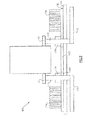
- FIG. 2 illustrates an example power bus contactor module 100 installed on a power distribution panel 120.
- the power bus contactor module 100 includes electric leads 112 that are connected to a power distribution bus bar 110 using contactor posts 114.
- the contactor posts 114 are maintained in position using a post support 116.
- the contactor module 100 controls power flow across the power distribution bus bar 110 utilizing standard internal switching relays that connect the bus bars 110 when power is desired to flow, and disconnect the bus bars 110 when no power flow is desired.
- the contactor module 100 is mounted on a non-conductive power distribution panel 120.
- the power distribution panel 120 mounts multiple power distribution components in a centralized location.
- a heat sink 130 is mounted on the power distribution panel 120.
- the heat sink 130 is connected to the power distribution panel 120 via a heat sink base 132.
- the heat sink includes multiple cooling fins 134 extending away from the heat sink base 132 and the power distribution panel 120.
- a thermally conductive polymer insert 140 connects the contactor posts 114 to the heat sink 130.
- the post support 116 abuts only the thermally conductive polymer insert 140 in order to prevent short circuiting the contactor module 100.
- a thermally conductive polymer is any polymer that is both thermally conductive and electrically insulative, such as a CoolPoly E-series plastic.
- heat generated in the contactor module 100 flows through the electric leads 112 into the contactor posts 114. From the contactor posts, the heat flows through the thermally conductive inserts 140 into the base 132 of the heat sink 130 and into the cooling fins 134. The heat is then dissipated into the ambient atmosphere from the heat sink base 132 and the cooling fins 134. A minimal amount of heat is similarly dissipated in the atmosphere from the leads 112 and the contactor posts 114.
- the cooling fins 134 increase the surface area of the heat sink 130, thereby increasing the amount of heat that can be dissipated in the ambient air in a smaller volume.
- FIGs 3A and 3B schematically illustrated a top view ( Figure 3A ) and a side view ( Figure 3B ) of a three phase contactor module mount 200 in a power distribution panel.
- Three pairs of contactor posts 220 protrude through a heat sink base 210 from a power distribution bus 250.
- the contactor posts 220 are electrically isolated from the heat sink base 210 via a thermally conductive insert 230.
- the heat sink includes multiple cooling fins 240 that operate dissipate heat into the surrounding atmosphere as described above with regards to Figure 1 .
- Figure 4 illustrates an alternate example contactor module 300 and mounting arrangement.
- the contactor module includes electric leads 312 connecting the contactor module to contactor posts 314.
- the contactor posts 314 connect the electric leads 312 to a power distribution bus bar 310, thereby allowing the contactor module 300 to control the flow of current through the power distribution bus bar 310.
- the power distribution panel of Figure 4 is a thermal ground plane 320.
- the thermal ground plane 320 includes a hollow core 324 that is partially filled with a coolant and includes multiple heat fins 322.
- an insert 330 constructed of a thermally conductive polymer electrically isolates the contactor posts 314 from the thermal ground plane 320.
- the portions of the thermal ground plane 320 immediately contacting the thermally conductive polymer insert 330 are evaporating surfaces 326, and the surfaces immediately contacting the cooling fins 322 are condensing surfaces 328.
- the generated heat conducts out of the contactor module 300 into the contactor posts 314 by way of the leads 312. From the leads, the heat conducts into the thermal ground plane 320 through the thermally conductive polymer insert 330. The heat enters the thermal ground plane 320 at the evaporating surface 326, which is immediately adjacent the contactor 314. As the evaporating surface heats up, the coolant within the thermal ground plane 320 converts from a liquid state into a gas state (evaporates). The evaporated coolant flows away from the evaporating surface 326 and contacts the cooler condensing surface 328 that is thermally removed from the evaporating surface 326. The condensing surface draws heat out of the evaporated coolant and into the cooling fins 322. This removal of heat from the coolant causes the coolant to return to a liquid form (condense).
- the condensed coolant contacts a wicking surface 329.
- the wicking surface 329 includes a wicking structure that draws the liquid coolant back towards the evaporating surface 326. Once the liquid coolant is returned to the evaporating surface, the liquid coolant evaporates again, and the cooling cycle is repeated. In this way, the heat is dissipated using both a coolant state change and cooling fin 322 dissipation into the ambient atmosphere.
- the contactor module mount is configured as in Figure 4 with the addition of a heat sink base providing an efficient thermal path directly from the contactor posts 314 to the cooling fins 322, thereby combining the contactor module mount of Figure 2 and the contactor module mount of Figure 4 .
- This combination recognizes benefits of both configurations with a minimal reduction in the effectiveness of each of the ambient air dissipation and thermal ground plane cooling methods.
Landscapes
- Engineering & Computer Science (AREA)
- Power Engineering (AREA)
- Cooling Or The Like Of Electrical Apparatus (AREA)
Abstract
Description
- The present disclosure is directed toward power distribution contactors, and more particularly to power distribution contactors including thermal management features.
- Commercial aircraft include onboard power systems typically including a power generation system and a power distribution system. The power systems are used to generate and distribute power during operation of the aircraft, and the power is used to power onboard electronic systems. As part of the power distribution system, electric contactors control power flow over a series of power distribution buses. The contactors control the flow of current in the bus bars, and mechanically switch current on or off as needed by the power systems.
- Due to the switching within the contactor modules, the contactors generate heat during operation of the power distribution system. Heat from the contactor leads is conducted to external power distribution bus bars and from the external power distribution bus bars into the ambient atmosphere. To accommodate this cooling feature, the external power distribution bus bars are sized large enough that the heat can be properly dissipated. An additional step utilized to facilitate the additional heat dissipation requirements is the utilization of copper, in place of the lighter weight aluminum, as the primary metal of the bus bars. Utilization of a heavier material increases the weight of the bus bar and the overall power distribution assembly.
- Disclosed is a power distribution system including a bus bar contactor having a contactor circuit with a plurality of contactor leads, a plurality of electrically and thermally conductive contactor posts operable to connect the contactor leads to a bus bar, a mounting panel face, wherein each of the contactor posts is received in the mounting panel face and extends through the mounting panel face, a first heat dissipation component thermally connected to each of the contactor posts, wherein the thermal connection is via a thermally conductive and electrically insulative polymer insert, and wherein each of the posts protrudes through the first heat sink.
- Also disclosed is a power distribution contactor mount including a plurality of electrically and thermally conductive contactor posts operable to connect contactor leads to a bus bar, a mounting panel face, wherein each of the contactor posts is received in the mounting panel face and extends through the mounting panel face, a first heat dissipation component mounted on the mounting panel face and thermally connected to each of the contactor posts, wherein the thermal connection is via a thermally conductive and electrically insulative polymer insert, and wherein each of the posts protrudes through said first heat dissipation component.
- Also disclosed is a method for cooling a power distribution contactor including the steps of thermally connecting a power distribution contactor to a heat dissipation feature using a thermally conductive polymer insert and dissipating heat using the heat dissipation feature.
-
-
Figure 1 schematically illustrates an aircraft power distribution system. -
Figure 2 schematically illustrates a bus bar contactor module installed in a power distribution panel. -
Figure 3A schematically illustrates a front view of a three phase contactor module mount in a power distribution panel. -
Figure 3B schematically illustrates a side view of the three phase contactor module mount ofFigure 3A . -
Figure 4 schematically illustrates a second alternate example bus bar contactor module installed in a power distribution pane. -
Figure 1 schematically illustrates anaircraft 10. During operation of theaircraft 10, electric power is generated in agenerator 20 using mechanical rotation of ajet engine 22. The electric power generated in thegenerator 20 is passed to apower distribution system 30 that usescontactors 32 to control power distribution overpower conduits 40 and thereby distribute electric power to multiple on boardelectric systems 50 as needed. - The
contactors 32 are mounted in a power distribution panel and operate to control current through thepower distribution system 30 by switching a mechanical relay, or an electrical equivalent of a mechanical relay. As a result of this functionality, each of thecontactor modules 32 generates heat. In order to prevent an undesirable buildup of heat within thepower distribution system 30, the heat is shunted to an attached bus bar being controlled by thecontactor modules 32 and the heat is dissipated into the ambient air from the bus bar. -
Figure 2 illustrates an example powerbus contactor module 100 installed on apower distribution panel 120. The powerbus contactor module 100 includeselectric leads 112 that are connected to a powerdistribution bus bar 110 usingcontactor posts 114. Thecontactor posts 114 are maintained in position using apost support 116. Thecontactor module 100 controls power flow across the powerdistribution bus bar 110 utilizing standard internal switching relays that connect thebus bars 110 when power is desired to flow, and disconnect thebus bars 110 when no power flow is desired. - The
contactor module 100 is mounted on a non-conductivepower distribution panel 120. In a typical arrangement, thepower distribution panel 120 mounts multiple power distribution components in a centralized location. - Also mounted on the
power distribution panel 120 is aheat sink 130. Theheat sink 130 is connected to thepower distribution panel 120 via a heat sink base 132. The heat sink includesmultiple cooling fins 134 extending away from the heat sink base 132 and thepower distribution panel 120. As the non-conductivepower distribution panel 120 is not thermally conductive, and the utilization of an electrically conductive connection to theheat sink 130 would cause thecontactor module 100 to be shorted across theheat sink 130, a thermallyconductive polymer insert 140 connects thecontactor posts 114 to theheat sink 130. Similarly, the post support 116 abuts only the thermally conductive polymer insert 140 in order to prevent short circuiting thecontactor module 100. For the purposes of this application, a thermally conductive polymer is any polymer that is both thermally conductive and electrically insulative, such as a CoolPoly E-series plastic. - The action of switching power, as well as the flow of power through the
contactor module 100, generates large amounts of heat that builds up to undesirable levels if the heat is not dissipated into the surrounding atmosphere. In the illustrated example ofFigure 2 , heat generated in thecontactor module 100 flows through theelectric leads 112 into thecontactor posts 114. From the contactor posts, the heat flows through the thermallyconductive inserts 140 into the base 132 of theheat sink 130 and into thecooling fins 134. The heat is then dissipated into the ambient atmosphere from the heat sink base 132 and thecooling fins 134. A minimal amount of heat is similarly dissipated in the atmosphere from theleads 112 and thecontactor posts 114. Thecooling fins 134 increase the surface area of theheat sink 130, thereby increasing the amount of heat that can be dissipated in the ambient air in a smaller volume. -
Figures 3A and 3B schematically illustrated a top view (Figure 3A ) and a side view (Figure 3B ) of a three phasecontactor module mount 200 in a power distribution panel. Three pairs of contactor posts 220 (one pair per phase) protrude through aheat sink base 210 from apower distribution bus 250. Thecontactor posts 220 are electrically isolated from theheat sink base 210 via a thermallyconductive insert 230. The heat sink includesmultiple cooling fins 240 that operate dissipate heat into the surrounding atmosphere as described above with regards toFigure 1 . -
Figure 4 illustrates an alternateexample contactor module 300 and mounting arrangement. As with the example ofFigure 1 , the contactor module includeselectric leads 312 connecting the contactor module tocontactor posts 314. Thecontactor posts 314 connect theelectric leads 312 to a powerdistribution bus bar 310, thereby allowing thecontactor module 300 to control the flow of current through the powerdistribution bus bar 310. - In place of the non-conductive power distribution panel of the example of
Figure 1 , the power distribution panel ofFigure 4 is athermal ground plane 320. Thethermal ground plane 320 includes ahollow core 324 that is partially filled with a coolant and includesmultiple heat fins 322. In order to accommodate thethermal ground plane 320, aninsert 330 constructed of a thermally conductive polymer electrically isolates thecontactor posts 314 from thethermal ground plane 320. The portions of thethermal ground plane 320 immediately contacting the thermallyconductive polymer insert 330 are evaporatingsurfaces 326, and the surfaces immediately contacting thecooling fins 322 are condensingsurfaces 328. - During operation of the
contactor module 300, the generated heat conducts out of thecontactor module 300 into thecontactor posts 314 by way of theleads 312. From the leads, the heat conducts into thethermal ground plane 320 through the thermally conductive polymer insert 330. The heat enters thethermal ground plane 320 at the evaporatingsurface 326, which is immediately adjacent thecontactor 314. As the evaporating surface heats up, the coolant within thethermal ground plane 320 converts from a liquid state into a gas state (evaporates). The evaporated coolant flows away from the evaporatingsurface 326 and contacts thecooler condensing surface 328 that is thermally removed from the evaporatingsurface 326. The condensing surface draws heat out of the evaporated coolant and into thecooling fins 322. This removal of heat from the coolant causes the coolant to return to a liquid form (condense). - The condensed coolant contacts a
wicking surface 329. Thewicking surface 329 includes a wicking structure that draws the liquid coolant back towards the evaporatingsurface 326. Once the liquid coolant is returned to the evaporating surface, the liquid coolant evaporates again, and the cooling cycle is repeated. In this way, the heat is dissipated using both a coolant state change andcooling fin 322 dissipation into the ambient atmosphere. - In another alternate example, the contactor module mount is configured as in
Figure 4 with the addition of a heat sink base providing an efficient thermal path directly from the contactor posts 314 to the coolingfins 322, thereby combining the contactor module mount ofFigure 2 and the contactor module mount ofFigure 4 . This combination recognizes benefits of both configurations with a minimal reduction in the effectiveness of each of the ambient air dissipation and thermal ground plane cooling methods. - Although an embodiment of this invention has been disclosed, a worker of ordinary skill in this art would recognize that certain modifications would come within the scope of this invention. For that reason, the following claims should be studied to determine the true scope and content of this invention.
Claims (15)
- A power distribution system comprising:a bus bar contactor having a contactor circuit with a plurality of contactor leads, a plurality of electrically and thermally conductive contactor posts (114, 314) operable to connect said contactor leads to a bus bar (110);a mounting panel face, wherein each of said contactor posts (114, 314) is received in said mounting panel face and extends through said mounting panel face; anda heat dissipation component thermally connected to each of said contactor posts (114, 314), wherein said thermal connection is via one of a plurality of a thermally conductive and electrically insulative polymer inserts (140, 330), and wherein each of said posts (114, 314) protrudes through said heat dissipation component.
- The power distribution system of claim 1, wherein each of said contactor posts (114, 314) further comprises a structural block (116) operable to maintain said contactor post in position.
- The power distribution system of claim 1, wherein said heat dissipation component is electrically conductive.
- A power distribution contactor mount comprising:a plurality of electrically and thermally conductive contactor posts (114, 314) operable to connect said contactor leads to a bus bar (110);a mounting panel face, wherein each of said contactor posts (114, 314) is received in said mounting panel face and extends through said mounting panel face;a heat dissipation component mounted on said mounting panel face and thermally connected to each of said contactor posts (114, 314), wherein said thermal connection is via a thermally conductive and electrically insulative polymer insert (140, 330), and wherein each of said posts (114, 314) protrudes through said first heat dissipation component.
- The power distribution system of claim 1 or the power distribution contactor mount of claim 4, wherein said heat dissipation component comprises a perforated heat sink base contacting said mounting panel face and a plurality of heat sink cooling fins (134, 240) extending outward from said perforated base.
- The power distribution system of claim 1 or the power distribution contactor of claim 4, wherein said mounting panel face is a hollow thermal ground plane (320), and wherein said heat dissipation component is said thermal ground plane (320).
- The power distribution system or the power distribution contactor of claim 4, wherein said thermal ground plane (320) includes a plurality of evaporating surfaces, each of said evaporating surfaces thermally contacting one of said plurality of contactor posts (114, 314) through at least one of said plurality of inserts (140, 330).
- The power distribution system or the power distribution contactor of claim 7, wherein said thermal ground plane (320) further comprises at least one condensing plane (320) thermally removed from said evaporating surfaces.
- The power distribution system or the power distribution contactor of claim 8, further comprising a wick structure operable to drive a condensed coolant to said evaporating surface.
- The power distribution system or the power distribution contactor of claim 7, wherein said thermal ground plane (320) is at least partially filled with an evaporating dielectric fluid.
- The power distribution contactor of claim 7, wherein said thermal ground plane (320) comprises a plurality of heat fins (322) extending away from said hollow ground plane (320).
- The power distribution system of claim 6, wherein said heat dissipation component comprises a plurality of heat fins extending away from said hollow ground plane (320).
- A method for cooling a power distribution contactor comprising the step of:thermally connecting a power distribution contactor to a heat dissipation feature using a thermally conductive polymer insert (140, 330); anddissipating heat using said heat dissipation feature.
- The method of claim 13, wherein the step of dissipating heat using said heat dissipation feature comprises dissipating said heat using a state change of a coolant within a thermal ground plane.
- The method of claim 13, wherein said step of dissipating heat using said heat dissipation feature comprises dissipating said heat using heat transfer from a plurality of cooling fins (134, 240) into an ambient atmosphere.
Applications Claiming Priority (1)
| Application Number | Priority Date | Filing Date | Title |
|---|---|---|---|
| US13/626,029 US9153946B2 (en) | 2012-09-25 | 2012-09-25 | Electrical contactor arrangement with thermal management |
Publications (2)
| Publication Number | Publication Date |
|---|---|
| EP2712040A1 true EP2712040A1 (en) | 2014-03-26 |
| EP2712040B1 EP2712040B1 (en) | 2017-07-26 |
Family
ID=49162006
Family Applications (1)
| Application Number | Title | Priority Date | Filing Date |
|---|---|---|---|
| EP13183902.9A Active EP2712040B1 (en) | 2012-09-25 | 2013-09-11 | Electrical contactor arrangement with thermal management |
Country Status (2)
| Country | Link |
|---|---|
| US (1) | US9153946B2 (en) |
| EP (1) | EP2712040B1 (en) |
Cited By (7)
| Publication number | Priority date | Publication date | Assignee | Title |
|---|---|---|---|---|
| EP2928274A3 (en) * | 2014-04-04 | 2015-11-04 | Hamilton Sundstrand Corporation | Solid-state stacked die contactors |
| EP3109957A1 (en) * | 2015-06-26 | 2016-12-28 | Hamilton Sundstrand Corporation | Power distribution panel having contactor with thermal management feature |
| EP3270402A1 (en) * | 2016-07-11 | 2018-01-17 | Hamilton Sundstrand Corporation | Electrical contactor and panel assemblies |
| EP3319100A1 (en) * | 2016-11-04 | 2018-05-09 | Hamilton Sundstrand Corporation | Integrated panel level liquid cooling for bus bars |
| EP3419035A1 (en) * | 2017-06-20 | 2018-12-26 | Hamilton Sundstrand Corporation | Integrated contactor mounting post |
| CN110783822A (en) * | 2019-11-01 | 2020-02-11 | 俞阳贞 | Combined power distribution cabinet |
| GB2611787A (en) * | 2021-10-14 | 2023-04-19 | Eaton Intelligent Power Ltd | Switchable contacting device with cooling functionality |
Families Citing this family (18)
| Publication number | Priority date | Publication date | Assignee | Title |
|---|---|---|---|---|
| US9137925B2 (en) * | 2013-05-08 | 2015-09-15 | Hamilton Sundstrand Corporation | Heat sink for contactor in power distribution assembly |
| JP2016018924A (en) * | 2014-07-09 | 2016-02-01 | 矢崎総業株式会社 | Heat dissipation structure of semiconductor breaker |
| US9728347B2 (en) * | 2014-12-16 | 2017-08-08 | Hamilton Sundstrand Corporation | Integrated contactor mounting and power distribution system and method |
| US9882357B2 (en) | 2015-06-26 | 2018-01-30 | Hamilton Sundstrand Corporation | Power distribution panel connector having thermal management feature |
| GB2545446B (en) | 2015-12-16 | 2018-08-22 | Ge Aviat Systems Ltd | Power distribution connector |
| US10305261B2 (en) * | 2016-03-25 | 2019-05-28 | Hamilton Sundstrand Corporation | Power distribution system |
| US9991655B2 (en) | 2016-06-29 | 2018-06-05 | Hamilton Sundstrand Corporation | Contactor in power distribution assembly |
| US10177542B2 (en) * | 2017-02-10 | 2019-01-08 | Hamilton Sundstrand Corporation | Contactor health monitoring systems and methods |
| US10825630B2 (en) * | 2018-04-05 | 2020-11-03 | Hamilton Sundstrand Corporation | Integrated mounting post and heat sink for contactor arrangement in power distribution system |
| US11858437B2 (en) | 2018-10-31 | 2024-01-02 | Lear Corporation | Electrical assembly |
| US11735891B2 (en) | 2018-10-31 | 2023-08-22 | Lear Corporation | Electrical assembly |
| US12500398B2 (en) | 2018-10-31 | 2025-12-16 | Lear Corporation | Electrical assembly |
| US11558963B2 (en) | 2018-10-31 | 2023-01-17 | Lear Corporation | Electrical assembly |
| US11721956B2 (en) | 2018-10-31 | 2023-08-08 | Lear Corporation | Electrical assembly |
| US10971873B2 (en) | 2018-10-31 | 2021-04-06 | Lear Corporation | Electrical unit with cooling member |
| US10930460B2 (en) * | 2019-02-14 | 2021-02-23 | Song Chuan Precision Co., Ltd. | Relay structure with heat dissipation function |
| DE102021130486B4 (en) | 2021-04-06 | 2024-07-18 | Lear Corporation | Electrical arrangement |
| US12144156B2 (en) | 2022-05-14 | 2024-11-12 | Hamilton Sundstrand Corporation | Cooling for power distribution systems |
Citations (2)
| Publication number | Priority date | Publication date | Assignee | Title |
|---|---|---|---|---|
| US7837496B1 (en) * | 2009-11-17 | 2010-11-23 | Hamilton Sundstrand Corporation | Contactor mounting assembly with improved thermal characteristics |
| US20110235244A1 (en) * | 2010-03-29 | 2011-09-29 | Mills Patrick W | Plug-in circuit breaker assembly |
Family Cites Families (8)
| Publication number | Priority date | Publication date | Assignee | Title |
|---|---|---|---|---|
| US5670936A (en) | 1995-04-26 | 1997-09-23 | Emerson Electric Co. | Power controller enclosure |
| DE102007032680A1 (en) * | 2007-07-13 | 2009-01-22 | Etel S.A. | Synchronous motor with several coil segments |
| US7570146B2 (en) | 2007-07-25 | 2009-08-04 | Eaton Corporation | Circuit breaker including ambient compensation bimetal holding and releasing arc fault indicator |
| US8138864B2 (en) | 2009-06-01 | 2012-03-20 | Eaton Corporation | Circuit interrupter including a molded case made of liquid crystal polymer |
| US8445800B2 (en) | 2010-12-17 | 2013-05-21 | Eaton Corporation | Electrical system, and circuit protection module and electrical switching apparatus therefor |
| US9142364B2 (en) * | 2012-06-29 | 2015-09-22 | Hamilton Sundstrand Corporation | Contactor mounting panel with improved thermal characteristics |
| US9245699B2 (en) * | 2012-10-02 | 2016-01-26 | Hamilton Sundstrand Corporation | Circuit breaker module |
| US9137925B2 (en) * | 2013-05-08 | 2015-09-15 | Hamilton Sundstrand Corporation | Heat sink for contactor in power distribution assembly |
-
2012
- 2012-09-25 US US13/626,029 patent/US9153946B2/en active Active
-
2013
- 2013-09-11 EP EP13183902.9A patent/EP2712040B1/en active Active
Patent Citations (2)
| Publication number | Priority date | Publication date | Assignee | Title |
|---|---|---|---|---|
| US7837496B1 (en) * | 2009-11-17 | 2010-11-23 | Hamilton Sundstrand Corporation | Contactor mounting assembly with improved thermal characteristics |
| US20110235244A1 (en) * | 2010-03-29 | 2011-09-29 | Mills Patrick W | Plug-in circuit breaker assembly |
Cited By (13)
| Publication number | Priority date | Publication date | Assignee | Title |
|---|---|---|---|---|
| EP2928274A3 (en) * | 2014-04-04 | 2015-11-04 | Hamilton Sundstrand Corporation | Solid-state stacked die contactors |
| US10109542B2 (en) | 2014-04-04 | 2018-10-23 | Hamilton Sundstrand Corporation | Solid-state stacked die contactors |
| EP3109957A1 (en) * | 2015-06-26 | 2016-12-28 | Hamilton Sundstrand Corporation | Power distribution panel having contactor with thermal management feature |
| EP3270402A1 (en) * | 2016-07-11 | 2018-01-17 | Hamilton Sundstrand Corporation | Electrical contactor and panel assemblies |
| EP3319100A1 (en) * | 2016-11-04 | 2018-05-09 | Hamilton Sundstrand Corporation | Integrated panel level liquid cooling for bus bars |
| US10057974B2 (en) | 2016-11-04 | 2018-08-21 | Hamilton Sundstrand Corporation | Integrated panel level liquid cooling for bus bars |
| EP3419035A1 (en) * | 2017-06-20 | 2018-12-26 | Hamilton Sundstrand Corporation | Integrated contactor mounting post |
| US10270231B2 (en) | 2017-06-20 | 2019-04-23 | Hamilton Sundstrand Corporation | Integrated contactor mounting post |
| US10673211B2 (en) | 2017-06-20 | 2020-06-02 | Hamilton Sunstrand Corporation | Integrated contactor mounting post |
| CN110783822A (en) * | 2019-11-01 | 2020-02-11 | 俞阳贞 | Combined power distribution cabinet |
| CN110783822B (en) * | 2019-11-01 | 2021-02-12 | 南通艺顺鹏电气有限公司 | Combined power distribution cabinet |
| GB2611787A (en) * | 2021-10-14 | 2023-04-19 | Eaton Intelligent Power Ltd | Switchable contacting device with cooling functionality |
| WO2023061623A1 (en) * | 2021-10-14 | 2023-04-20 | Eaton Intelligent Power Limited | Switchable contacting device with cooling functionality |
Also Published As
| Publication number | Publication date |
|---|---|
| US9153946B2 (en) | 2015-10-06 |
| US20140087584A1 (en) | 2014-03-27 |
| EP2712040B1 (en) | 2017-07-26 |
Similar Documents
| Publication | Publication Date | Title |
|---|---|---|
| US9153946B2 (en) | Electrical contactor arrangement with thermal management | |
| US9142364B2 (en) | Contactor mounting panel with improved thermal characteristics | |
| EP3319100B1 (en) | Integrated panel level liquid cooling for bus bars | |
| US9613764B1 (en) | Contactor body with integral heat sink | |
| EP2978074B1 (en) | Power distribution system | |
| US7837496B1 (en) | Contactor mounting assembly with improved thermal characteristics | |
| CN104754918A (en) | Electronic control unit and electric power steering apparatus having the same | |
| US10103521B2 (en) | Electrical power distribution plate comprising a protected distribution bar | |
| EP2717285B1 (en) | Circuit Breaker Module | |
| EP2892310A2 (en) | Heat sink for contactor in power distribution assembly | |
| JP2016220277A (en) | Electric connection box | |
| EP3109957B1 (en) | Power distribution panel having contactor with thermal management feature | |
| CN108604789A (en) | Electrical Equipment | |
| JPH08294266A (en) | Power module and power converter | |
| US20140285970A1 (en) | Electric Power Conversion System | |
| US11343942B2 (en) | Power conversion device including cooling components | |
| CN204425196U (en) | A kind of power cabinet heat abstractor of photovoltaic DC-to-AC converter | |
| CN104733409A (en) | carrier module with bridging element for a semiconductor element | |
| EP2254152B1 (en) | Solid state switch arrangement and method of arranging a switch | |
| EP3109956B1 (en) | Aircraft power distribution panel having thermal management feature | |
| JP6713246B2 (en) | Power converter | |
| CN104115268A (en) | Electrical component cooling device and heat source machine of refrigeration cycle device provided with same | |
| CN111211607A (en) | Method and system for heat removal at a current compensation circuit | |
| JP6442381B2 (en) | Fixing structure of heating element, power conversion unit and power conversion device | |
| EP3056834A1 (en) | Electrical heating device |
Legal Events
| Date | Code | Title | Description |
|---|---|---|---|
| PUAI | Public reference made under article 153(3) epc to a published international application that has entered the european phase |
Free format text: ORIGINAL CODE: 0009012 |
|
| AK | Designated contracting states |
Kind code of ref document: A1 Designated state(s): AL AT BE BG CH CY CZ DE DK EE ES FI FR GB GR HR HU IE IS IT LI LT LU LV MC MK MT NL NO PL PT RO RS SE SI SK SM TR |
|
| AX | Request for extension of the european patent |
Extension state: BA ME |
|
| 17P | Request for examination filed |
Effective date: 20140916 |
|
| RBV | Designated contracting states (corrected) |
Designated state(s): AL AT BE BG CH CY CZ DE DK EE ES FI FR GB GR HR HU IE IS IT LI LT LU LV MC MK MT NL NO PL PT RO RS SE SI SK SM TR |
|
| 17Q | First examination report despatched |
Effective date: 20160816 |
|
| STAA | Information on the status of an ep patent application or granted ep patent |
Free format text: STATUS: EXAMINATION IS IN PROGRESS |
|
| GRAP | Despatch of communication of intention to grant a patent |
Free format text: ORIGINAL CODE: EPIDOSNIGR1 |
|
| STAA | Information on the status of an ep patent application or granted ep patent |
Free format text: STATUS: GRANT OF PATENT IS INTENDED |
|
| RIC1 | Information provided on ipc code assigned before grant |
Ipc: H02B 1/056 20060101AFI20170214BHEP Ipc: H01H 9/52 20060101ALN20170214BHEP Ipc: H02B 1/56 20060101ALN20170214BHEP Ipc: H02B 1/20 20060101ALN20170214BHEP |
|
| INTG | Intention to grant announced |
Effective date: 20170308 |
|
| GRAS | Grant fee paid |
Free format text: ORIGINAL CODE: EPIDOSNIGR3 |
|
| GRAA | (expected) grant |
Free format text: ORIGINAL CODE: 0009210 |
|
| STAA | Information on the status of an ep patent application or granted ep patent |
Free format text: STATUS: THE PATENT HAS BEEN GRANTED |
|
| AK | Designated contracting states |
Kind code of ref document: B1 Designated state(s): AL AT BE BG CH CY CZ DE DK EE ES FI FR GB GR HR HU IE IS IT LI LT LU LV MC MK MT NL NO PL PT RO RS SE SI SK SM TR |
|
| REG | Reference to a national code |
Ref country code: GB Ref legal event code: FG4D |
|
| REG | Reference to a national code |
Ref country code: CH Ref legal event code: EP |
|
| REG | Reference to a national code |
Ref country code: AT Ref legal event code: REF Ref document number: 913123 Country of ref document: AT Kind code of ref document: T Effective date: 20170815 |
|
| REG | Reference to a national code |
Ref country code: FR Ref legal event code: PLFP Year of fee payment: 5 |
|
| REG | Reference to a national code |
Ref country code: IE Ref legal event code: FG4D |
|
| REG | Reference to a national code |
Ref country code: DE Ref legal event code: R096 Ref document number: 602013023959 Country of ref document: DE |
|
| REG | Reference to a national code |
Ref country code: NL Ref legal event code: MP Effective date: 20170726 |
|
| REG | Reference to a national code |
Ref country code: LT Ref legal event code: MG4D |
|
| REG | Reference to a national code |
Ref country code: AT Ref legal event code: MK05 Ref document number: 913123 Country of ref document: AT Kind code of ref document: T Effective date: 20170726 |
|
| PG25 | Lapsed in a contracting state [announced via postgrant information from national office to epo] |
Ref country code: NL Free format text: LAPSE BECAUSE OF FAILURE TO SUBMIT A TRANSLATION OF THE DESCRIPTION OR TO PAY THE FEE WITHIN THE PRESCRIBED TIME-LIMIT Effective date: 20170726 Ref country code: LT Free format text: LAPSE BECAUSE OF FAILURE TO SUBMIT A TRANSLATION OF THE DESCRIPTION OR TO PAY THE FEE WITHIN THE PRESCRIBED TIME-LIMIT Effective date: 20170726 Ref country code: FI Free format text: LAPSE BECAUSE OF FAILURE TO SUBMIT A TRANSLATION OF THE DESCRIPTION OR TO PAY THE FEE WITHIN THE PRESCRIBED TIME-LIMIT Effective date: 20170726 Ref country code: SE Free format text: LAPSE BECAUSE OF FAILURE TO SUBMIT A TRANSLATION OF THE DESCRIPTION OR TO PAY THE FEE WITHIN THE PRESCRIBED TIME-LIMIT Effective date: 20170726 Ref country code: NO Free format text: LAPSE BECAUSE OF FAILURE TO SUBMIT A TRANSLATION OF THE DESCRIPTION OR TO PAY THE FEE WITHIN THE PRESCRIBED TIME-LIMIT Effective date: 20171026 Ref country code: HR Free format text: LAPSE BECAUSE OF FAILURE TO SUBMIT A TRANSLATION OF THE DESCRIPTION OR TO PAY THE FEE WITHIN THE PRESCRIBED TIME-LIMIT Effective date: 20170726 Ref country code: AT Free format text: LAPSE BECAUSE OF FAILURE TO SUBMIT A TRANSLATION OF THE DESCRIPTION OR TO PAY THE FEE WITHIN THE PRESCRIBED TIME-LIMIT Effective date: 20170726 |
|
| PG25 | Lapsed in a contracting state [announced via postgrant information from national office to epo] |
Ref country code: BG Free format text: LAPSE BECAUSE OF FAILURE TO SUBMIT A TRANSLATION OF THE DESCRIPTION OR TO PAY THE FEE WITHIN THE PRESCRIBED TIME-LIMIT Effective date: 20171026 Ref country code: ES Free format text: LAPSE BECAUSE OF FAILURE TO SUBMIT A TRANSLATION OF THE DESCRIPTION OR TO PAY THE FEE WITHIN THE PRESCRIBED TIME-LIMIT Effective date: 20170726 Ref country code: LV Free format text: LAPSE BECAUSE OF FAILURE TO SUBMIT A TRANSLATION OF THE DESCRIPTION OR TO PAY THE FEE WITHIN THE PRESCRIBED TIME-LIMIT Effective date: 20170726 Ref country code: GR Free format text: LAPSE BECAUSE OF FAILURE TO SUBMIT A TRANSLATION OF THE DESCRIPTION OR TO PAY THE FEE WITHIN THE PRESCRIBED TIME-LIMIT Effective date: 20171027 Ref country code: RS Free format text: LAPSE BECAUSE OF FAILURE TO SUBMIT A TRANSLATION OF THE DESCRIPTION OR TO PAY THE FEE WITHIN THE PRESCRIBED TIME-LIMIT Effective date: 20170726 Ref country code: PL Free format text: LAPSE BECAUSE OF FAILURE TO SUBMIT A TRANSLATION OF THE DESCRIPTION OR TO PAY THE FEE WITHIN THE PRESCRIBED TIME-LIMIT Effective date: 20170726 Ref country code: IS Free format text: LAPSE BECAUSE OF FAILURE TO SUBMIT A TRANSLATION OF THE DESCRIPTION OR TO PAY THE FEE WITHIN THE PRESCRIBED TIME-LIMIT Effective date: 20171126 |
|
| REG | Reference to a national code |
Ref country code: DE Ref legal event code: R119 Ref document number: 602013023959 Country of ref document: DE |
|
| PG25 | Lapsed in a contracting state [announced via postgrant information from national office to epo] |
Ref country code: CZ Free format text: LAPSE BECAUSE OF FAILURE TO SUBMIT A TRANSLATION OF THE DESCRIPTION OR TO PAY THE FEE WITHIN THE PRESCRIBED TIME-LIMIT Effective date: 20170726 Ref country code: RO Free format text: LAPSE BECAUSE OF FAILURE TO SUBMIT A TRANSLATION OF THE DESCRIPTION OR TO PAY THE FEE WITHIN THE PRESCRIBED TIME-LIMIT Effective date: 20170726 Ref country code: DK Free format text: LAPSE BECAUSE OF FAILURE TO SUBMIT A TRANSLATION OF THE DESCRIPTION OR TO PAY THE FEE WITHIN THE PRESCRIBED TIME-LIMIT Effective date: 20170726 |
|
| REG | Reference to a national code |
Ref country code: CH Ref legal event code: PL |
|
| PG25 | Lapsed in a contracting state [announced via postgrant information from national office to epo] |
Ref country code: SK Free format text: LAPSE BECAUSE OF FAILURE TO SUBMIT A TRANSLATION OF THE DESCRIPTION OR TO PAY THE FEE WITHIN THE PRESCRIBED TIME-LIMIT Effective date: 20170726 Ref country code: EE Free format text: LAPSE BECAUSE OF FAILURE TO SUBMIT A TRANSLATION OF THE DESCRIPTION OR TO PAY THE FEE WITHIN THE PRESCRIBED TIME-LIMIT Effective date: 20170726 Ref country code: SM Free format text: LAPSE BECAUSE OF FAILURE TO SUBMIT A TRANSLATION OF THE DESCRIPTION OR TO PAY THE FEE WITHIN THE PRESCRIBED TIME-LIMIT Effective date: 20170726 Ref country code: MC Free format text: LAPSE BECAUSE OF FAILURE TO SUBMIT A TRANSLATION OF THE DESCRIPTION OR TO PAY THE FEE WITHIN THE PRESCRIBED TIME-LIMIT Effective date: 20170726 Ref country code: IT Free format text: LAPSE BECAUSE OF FAILURE TO SUBMIT A TRANSLATION OF THE DESCRIPTION OR TO PAY THE FEE WITHIN THE PRESCRIBED TIME-LIMIT Effective date: 20170726 |
|
| PLBE | No opposition filed within time limit |
Free format text: ORIGINAL CODE: 0009261 |
|
| STAA | Information on the status of an ep patent application or granted ep patent |
Free format text: STATUS: NO OPPOSITION FILED WITHIN TIME LIMIT |
|
| REG | Reference to a national code |
Ref country code: IE Ref legal event code: MM4A |
|
| REG | Reference to a national code |
Ref country code: BE Ref legal event code: MM Effective date: 20170930 |
|
| PG25 | Lapsed in a contracting state [announced via postgrant information from national office to epo] |
Ref country code: LU Free format text: LAPSE BECAUSE OF NON-PAYMENT OF DUE FEES Effective date: 20170911 |
|
| 26N | No opposition filed |
Effective date: 20180430 |
|
| PG25 | Lapsed in a contracting state [announced via postgrant information from national office to epo] |
Ref country code: LI Free format text: LAPSE BECAUSE OF NON-PAYMENT OF DUE FEES Effective date: 20170930 Ref country code: CH Free format text: LAPSE BECAUSE OF NON-PAYMENT OF DUE FEES Effective date: 20170930 Ref country code: IE Free format text: LAPSE BECAUSE OF NON-PAYMENT OF DUE FEES Effective date: 20170911 Ref country code: DE Free format text: LAPSE BECAUSE OF NON-PAYMENT OF DUE FEES Effective date: 20180404 |
|
| REG | Reference to a national code |
Ref country code: FR Ref legal event code: PLFP Year of fee payment: 6 |
|
| PG25 | Lapsed in a contracting state [announced via postgrant information from national office to epo] |
Ref country code: BE Free format text: LAPSE BECAUSE OF NON-PAYMENT OF DUE FEES Effective date: 20170930 Ref country code: SI Free format text: LAPSE BECAUSE OF FAILURE TO SUBMIT A TRANSLATION OF THE DESCRIPTION OR TO PAY THE FEE WITHIN THE PRESCRIBED TIME-LIMIT Effective date: 20170726 |
|
| PG25 | Lapsed in a contracting state [announced via postgrant information from national office to epo] |
Ref country code: MT Free format text: LAPSE BECAUSE OF NON-PAYMENT OF DUE FEES Effective date: 20170911 |
|
| PG25 | Lapsed in a contracting state [announced via postgrant information from national office to epo] |
Ref country code: HU Free format text: LAPSE BECAUSE OF FAILURE TO SUBMIT A TRANSLATION OF THE DESCRIPTION OR TO PAY THE FEE WITHIN THE PRESCRIBED TIME-LIMIT; INVALID AB INITIO Effective date: 20130911 |
|
| PG25 | Lapsed in a contracting state [announced via postgrant information from national office to epo] |
Ref country code: CY Free format text: LAPSE BECAUSE OF NON-PAYMENT OF DUE FEES Effective date: 20170726 |
|
| PG25 | Lapsed in a contracting state [announced via postgrant information from national office to epo] |
Ref country code: MK Free format text: LAPSE BECAUSE OF FAILURE TO SUBMIT A TRANSLATION OF THE DESCRIPTION OR TO PAY THE FEE WITHIN THE PRESCRIBED TIME-LIMIT Effective date: 20170726 |
|
| PG25 | Lapsed in a contracting state [announced via postgrant information from national office to epo] |
Ref country code: TR Free format text: LAPSE BECAUSE OF FAILURE TO SUBMIT A TRANSLATION OF THE DESCRIPTION OR TO PAY THE FEE WITHIN THE PRESCRIBED TIME-LIMIT Effective date: 20170726 |
|
| PG25 | Lapsed in a contracting state [announced via postgrant information from national office to epo] |
Ref country code: PT Free format text: LAPSE BECAUSE OF FAILURE TO SUBMIT A TRANSLATION OF THE DESCRIPTION OR TO PAY THE FEE WITHIN THE PRESCRIBED TIME-LIMIT Effective date: 20170726 |
|
| PG25 | Lapsed in a contracting state [announced via postgrant information from national office to epo] |
Ref country code: AL Free format text: LAPSE BECAUSE OF FAILURE TO SUBMIT A TRANSLATION OF THE DESCRIPTION OR TO PAY THE FEE WITHIN THE PRESCRIBED TIME-LIMIT Effective date: 20170726 |
|
| P01 | Opt-out of the competence of the unified patent court (upc) registered |
Effective date: 20230522 |
|
| PGFP | Annual fee paid to national office [announced via postgrant information from national office to epo] |
Ref country code: GB Payment date: 20250822 Year of fee payment: 13 |
|
| PGFP | Annual fee paid to national office [announced via postgrant information from national office to epo] |
Ref country code: FR Payment date: 20250820 Year of fee payment: 13 |