EP2711963A1 - Electromagnetic contactor - Google Patents
Electromagnetic contactor Download PDFInfo
- Publication number
- EP2711963A1 EP2711963A1 EP12785581.5A EP12785581A EP2711963A1 EP 2711963 A1 EP2711963 A1 EP 2711963A1 EP 12785581 A EP12785581 A EP 12785581A EP 2711963 A1 EP2711963 A1 EP 2711963A1
- Authority
- EP
- European Patent Office
- Prior art keywords
- contact
- movable
- magnetic yoke
- disposed
- movable plunger
- Prior art date
- Legal status (The legal status is an assumption and is not a legal conclusion. Google has not performed a legal analysis and makes no representation as to the accuracy of the status listed.)
- Granted
Links
Images







Classifications
-
- H—ELECTRICITY
- H01—ELECTRIC ELEMENTS
- H01H—ELECTRIC SWITCHES; RELAYS; SELECTORS; EMERGENCY PROTECTIVE DEVICES
- H01H1/00—Contacts
- H01H1/06—Contacts characterised by the shape or structure of the contact-making surface, e.g. grooved
-
- H—ELECTRICITY
- H01—ELECTRIC ELEMENTS
- H01H—ELECTRIC SWITCHES; RELAYS; SELECTORS; EMERGENCY PROTECTIVE DEVICES
- H01H9/00—Details of switching devices, not covered by groups H01H1/00 - H01H7/00
- H01H9/30—Means for extinguishing or preventing arc between current-carrying parts
- H01H9/44—Means for extinguishing or preventing arc between current-carrying parts using blow-out magnet
- H01H9/443—Means for extinguishing or preventing arc between current-carrying parts using blow-out magnet using permanent magnets
-
- H—ELECTRICITY
- H01—ELECTRIC ELEMENTS
- H01H—ELECTRIC SWITCHES; RELAYS; SELECTORS; EMERGENCY PROTECTIVE DEVICES
- H01H50/00—Details of electromagnetic relays
- H01H50/14—Terminal arrangements
-
- H—ELECTRICITY
- H01—ELECTRIC ELEMENTS
- H01H—ELECTRIC SWITCHES; RELAYS; SELECTORS; EMERGENCY PROTECTIVE DEVICES
- H01H50/00—Details of electromagnetic relays
- H01H50/16—Magnetic circuit arrangements
- H01H50/163—Details concerning air-gaps, e.g. anti-remanence, damping, anti-corrosion
-
- H—ELECTRICITY
- H01—ELECTRIC ELEMENTS
- H01H—ELECTRIC SWITCHES; RELAYS; SELECTORS; EMERGENCY PROTECTIVE DEVICES
- H01H50/00—Details of electromagnetic relays
- H01H50/16—Magnetic circuit arrangements
- H01H50/36—Stationary parts of magnetic circuit, e.g. yoke
- H01H50/38—Part of main magnetic circuit shaped to suppress arcing between the contacts of the relay
-
- H—ELECTRICITY
- H01—ELECTRIC ELEMENTS
- H01H—ELECTRIC SWITCHES; RELAYS; SELECTORS; EMERGENCY PROTECTIVE DEVICES
- H01H50/00—Details of electromagnetic relays
- H01H50/16—Magnetic circuit arrangements
- H01H50/36—Stationary parts of magnetic circuit, e.g. yoke
- H01H50/42—Auxiliary magnetic circuits, e.g. for maintaining armature in, or returning armature to, position of rest, for damping or accelerating movement
-
- H—ELECTRICITY
- H01—ELECTRIC ELEMENTS
- H01H—ELECTRIC SWITCHES; RELAYS; SELECTORS; EMERGENCY PROTECTIVE DEVICES
- H01H51/00—Electromagnetic relays
- H01H51/02—Non-polarised relays
- H01H51/04—Non-polarised relays with single armature; with single set of ganged armatures
- H01H51/06—Armature is movable between two limit positions of rest and is moved in one direction due to energisation of an electromagnet and after the electromagnet is de-energised is returned by energy stored during the movement in the first direction, e.g. by using a spring, by using a permanent magnet, by gravity
- H01H51/065—Relays having a pair of normally open contacts rigidly fixed to a magnetic core movable along the axis of a solenoid, e.g. relays for starting automobiles
-
- H—ELECTRICITY
- H03—ELECTRONIC CIRCUITRY
- H03K—PULSE TECHNIQUE
- H03K17/00—Electronic switching or gating, i.e. not by contact-making and –breaking
- H03K17/51—Electronic switching or gating, i.e. not by contact-making and –breaking characterised by the components used
- H03K17/56—Electronic switching or gating, i.e. not by contact-making and –breaking characterised by the components used by the use, as active elements, of semiconductor devices
- H03K17/60—Electronic switching or gating, i.e. not by contact-making and –breaking characterised by the components used by the use, as active elements, of semiconductor devices the devices being bipolar transistors
- H03K17/68—Electronic switching or gating, i.e. not by contact-making and –breaking characterised by the components used by the use, as active elements, of semiconductor devices the devices being bipolar transistors specially adapted for switching AC currents or voltages
-
- H—ELECTRICITY
- H01—ELECTRIC ELEMENTS
- H01H—ELECTRIC SWITCHES; RELAYS; SELECTORS; EMERGENCY PROTECTIVE DEVICES
- H01H50/00—Details of electromagnetic relays
- H01H50/16—Magnetic circuit arrangements
- H01H50/18—Movable parts of magnetic circuits, e.g. armature
- H01H50/20—Movable parts of magnetic circuits, e.g. armature movable inside coil and substantially lengthwise with respect to axis thereof; movable coaxially with respect to coil
- H01H50/22—Movable parts of magnetic circuits, e.g. armature movable inside coil and substantially lengthwise with respect to axis thereof; movable coaxially with respect to coil wherein the magnetic circuit is substantially closed
Definitions
- the present invention relates to an electromagnetic contactor, including a contact device that includes fixed contacts and a movable contact and an electromagnet unit that drives the movable contact, interposed in a current path.
- An electromagnetic contactor that carries out switching of a current path is such that a movable contact is driven by an exciting coil and movable plunger of an electromagnet unit. That is, when the exciting coil is in a non-excited state, the movable plunger is biased by a return spring, and the movable contact is in a released condition wherein it is distanced from a pair of fixed contacts disposed maintaining a predetermined interval. From the released condition, the movable plunger can be moved against the return spring by exciting the exciting coil, and the movable contact takes on an engaged condition wherein it is in contact with the pair of fixed contacts (for example, refer to PLT 1).
- PLT 1 Japanese Patent No. 3,107,288
- the invention having been contrived focusing on the unsolved problem of the heretofore known example, has an object of providing an electromagnetic contactor such that it is possible to reduce the size of the overall configuration, even when switching a large current.
- an electromagnetic contactor includes a contact device in which are installed a pair of fixed contacts and a movable contact disposed so as to be connectable to and detachable from the pair of fixed contacts and an electromagnet unit including an exciting coil that drives a movable plunger connected via a connecting shaft to the movable contact of the contact device.
- the contact device has a configuration such that L-shaped portions having a contact portion and extending to a predetermined length in mutually facing directions are formed in the pair of fixed contacts disposed and fixed maintaining a predetermined interval, and the two ends of the movable contact are disposed so as to be connectable to and detachable from the contact portions of the L-shaped portion on the side opposite to that of the electromagnet unit.
- the electromagnet unit includes a magnetic yoke enclosing a plunger drive portion, a movable plunger whose leading end protrudes through an aperture formed in the magnetic yoke and which is biased by a return spring, and a ring-form permanent magnet, magnetized in the movable direction of the movable plunger, disposed and fixed so as to enclose a peripheral flange portion formed on the protruding end side of the movable plunger.
- the permanent magnet so as to enclose the peripheral flange portion of the movable plunger in the electromagnet unit, and by providing the auxiliary yoke, it is possible to cause suctioning force to act on the movable plunger so as to move the movable contact in a releasing direction, thus suppressing the biasing force of the return spring. Because of this, it is possible to reduce the magnetomotive force of the exciting coil, thus reducing the size of the electromagnet unit. Also, it is possible to suction the peripheral flange portion of the movable plunger with the magnetic force of the permanent magnet in the released condition, and thus possible to secure high anti-malfunction performance when releasing. As it is possible to reduce the biasing force of the return spring commensurately, it is possible to further reduce the height of the electromagnet unit.
- the electromagnetic contactor is such that the pair of fixed contacts is such that the L-shaped portion is modified to a C-shaped portion by forming opposing plate portions in positions such as to face each other from either side of the two ends of the movable contact, and an insulating cover that regulates arc generation is mounted on inner peripheral portions of the C-shaped portion other than the contact portion.
- the electromagnetic contactor is such that the contact device has a configuration such that the pair of fixed contacts and the movable contact are enclosed in a contact housing case, and an arc extinguishing permanent magnet is disposed along the movable contact on the inner peripheral surface side of the contact housing case.
- the arc extinguishing permanent magnet is disposed on the inner side of the insulating case, it is possible to bring the arc extinguishing permanent magnet near the portion between the pair of fixed contacts and the movable contact in which the arc is generated. Also, it is possible to form a large arc extinguishing space on the outer side of the arc extinguishing permanent magnet in a direction facing the pair of fixed contacts, and thus possible to reliably carry out the extinguishing of the arc.
- the electromagnetic contactor is such that the contact housing case is configured of a metal tubular body, one end of which is hermetically sealed to an upper magnetic yoke of the electromagnet unit, enclosing the pair of fixed contacts and the movable contact, a fixed contact support insulating substrate joined hermetically closing off an opened end plane of the metal tubular body and supporting the pair of fixed contacts, and an insulating tubular body disposed on the inner peripheral surface of the metal tubular body.
- the electromagnetic contactor is such that the movable contact is disposed so as to be movable via a contact spring in the flange portion formed on the leading end of the connecting shaft connected to the movable plunger, and a central portion supported by the connecting shaft and receiving the contact spring is a depressed portion protruding on the electromagnet unit side.
- the electromagnetic contactor may be such that the electromagnet unit includes a magnetic yoke of a U-shape in cross-section whose upper portion is opened, an upper magnetic yoke bridging the upper opened portion of the magnetic yoke, a spool disposed on a bottom surface plate portion of the magnetic yoke and having a central aperture in which an exciting coil is wound, a movable plunger, disposed in the central aperture of the spool so as to be movable in an axial direction, whose leading end protrudes through an aperture formed in the upper magnetic yoke and which is biased by a return spring, a ring-form permanent magnet, disposed and fixed on the upper magnetic yoke so as to enclose a peripheral flange portion formed on the leading end side of the movable plunger, and magnetized in an axial direction, and an auxiliary yoke fixed on the upper surface of the ring-form permanent magnet and in contact with the peripheral flange portion of the movable plunger
- the electromagnetic contactor is such that the electromagnet unit includes a ring-form auxiliary yoke that encloses side surfaces of a bottom surface side end portion of the U-shaped magnetic yoke of the movable plunger in a released position, wherein the length of a gap between the ring-form auxiliary yoke and the side surface of the movable plunger is set to be less than the length of a gap between the bottom surface side end portion of the movable plunger and the U-shaped magnetic yoke.
- an advantage is obtained in that it is possible to lower the height of the contact device in the movable direction of the movable contact, possible to reduce the size of the electromagnet unit, and thus possible to reduce the size of the configuration of the whole electromagnetic contactor.
- the arc extinguishing permanent magnet is disposed on the inner peripheral surface side along the movable contact in the contact housing case, an advantage is obtained in that there is generated a magnetic flux that crosses an arc generated in the contact portions of the pair of fixed contacts and movable contact when shifting from the engaged condition to the released condition, thus extending the arc, a large arc extinguishing space can be formed on the outer side of the permanent magnet in a direction facing the pair of fixed contacts, the necessary arc length is secured, and it is thus possible to reliably carry out the extinguishing of the arc.
- the movable plunger is suctioned by the permanent magnet when releasing, and it is possible to reliably prevent the movable contact from making unwanted contact with the pair of fixed contacts due to vibration, shock, or the like. Simultaneously with this, it is possible to reduce the biasing force of the return spring by the amount by which the movable plunger is suctioned by the permanent magnet, and thus possible to reduce the magnetomotive force of the exciting coil, and reduce the size of the electromagnet unit.
- Fig. 1 is a sectional view showing one example of an electromagnetic switch according to the invention
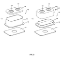
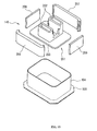
- Fig. 2 is an exploded perspective view of an arc extinguishing chamber.
- 10 is an electromagnetic contactor, and the electromagnetic contactor 10 is configured of a contact device 100 in which is disposed a contact mechanism, and an electromagnet unit 200 that drives the contact device 100.
- the contact device 100 has an arc extinguishing chamber 102 in which is housed a contact mechanism 101, as is clear from Fig. 1 and Fig. 2 .
- the arc extinguishing chamber 102 as shown in Fig. 2(a) , includes a metal square tubular body 104 having on a lower end portion a metal flange portion 103 protruding outward, and a fixed contact support insulating substrate 105 configured of a plate-like ceramic insulating substrate that closes off the upper end of the metal square tubular body 104.
- the metal square tubular body 104 is such that the flange portion 103 thereof is seal joined to an upper portion magnetic yoke 210 of the electromagnet unit 200, to be described hereafter.
- a metalizing process is performed around the through holes 106 and 107 on the upper surface side of the fixed contact support insulating substrate 105, and in a position on the lower surface side that comes into contact with the square tubular body 104.
- a metal foil is formed around the through holes 106 and 107 and in a position that comes into contact with the square tubular body 104.
- the contact mechanism 101 includes the pair of fixed contacts 111 and 112 inserted into and fixed in the through holes 106 and 107 of the fixed contact support insulating substrate 105 of the arc extinguishing chamber 102.
- Each of the fixed contacts 111 and 112 includes a support conductor portion 114, having on an upper end a flange portion protruding outward, inserted into the through holes 106 and 107 of the fixed contact support insulating substrate 105, and a C-shaped portion 115, the inner side of which is opened, linked to the support conductor portion 114 and disposed on the lower surface side of the fixed contact support insulating substrate 105.
- the C-shaped portion 115 is formed in a C-shape of an upper plate portion 116 extending to the outer side along the lower surface of the fixed contact support insulating substrate 105, an intermediate plate portion 117 extending downward from the outer side end portion of the upper plate portion 116, and a lower plate portion 118 extending from the lower end side of the intermediate plate portion 117, parallel with the upper plate portion 116, to the inner side, that is, in a direction facing the fixed contacts 111 and 112, wherein the upper plate portion 116 is added to an L-shape formed by the intermediate plate portion 117 and lower plate portion 118.
- the support conductor portion 114 and C-shaped portion 115 are fixed by, for example, brazing in a condition in which a pin 114a formed protruding on the lower end surface of the support conductor portion 114 is inserted into a through hole 120 formed in the upper plate portion 116 of the C-shaped portion 115.
- the fixing of the support conductor portion 114 and C-shaped portion 115 may be such that the pin 114a is fitted into the through hole 120, or an external thread is formed on the pin 114a and an internal thread is formed in the through hole 120, and the two are screwed together.
- a magnetic plate 119 of a C-shape when seen in plan view is mounted so as to cover the inner side surface of the intermediate plate portion 117 in the C-shaped portion 115 of the fixed contacts 111 and 112.
- a magnetic plate 119 By disposing the magnetic plate 119 so as to cover the inner side surface of the intermediate plate portion 117 in this way, it is possible to shield a magnetic field generated by current flowing through the intermediate plate portion 117.
- an insulating cover 121 made of a synthetic resin material, that regulates arc generation is mounted on the C-shaped portion 115 of each of the fixed contacts 111 and 112.
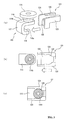
- the insulating cover 121 covers the inner peripheral surfaces of the upper plate portion 116 and intermediate plate portion 117 of the C-shaped portion 115, as shown in Figs. 3(a) and (b) .
- the insulating cover 121 includes an L-shaped plate portion 122 that follows the inner peripheral surfaces of the upper plate portion 116 and intermediate plate portion 117, side plate portions 123 and 124, each extending upward and outward from front and rear end portions of the L-shaped plate portion 122, that cover side surfaces of the upper plate portion 116 and intermediate plate portion 117 of the C-shaped portion 115, and a fitting portion 125, formed on the inward side from the upper end of the side plate portions 123 and 124, that fits onto a small diameter portion 114b formed on the support conductor portion 114 of the fixed contacts 111 and 112.
- the insulating cover 121 is placed in a condition in which the fitting portion 125 is facing the small diameter portion 114b of the support conductor portion 114 of the fixed contacts 111 and 112, as shown in Figs. 3(a) and (b) , after which, as shown in Fig. 3(c) , the fitting portion 125 is fitted into the small diameter portion 114b of the support conductor portion 114 by pushing the insulating cover 121.
- the insulating cover 121 is inserted from an upper aperture portion between the fixed contacts 111 and 112 in a condition vertically reverse of that in Figs. 3(a) to (c) , as shown in Fig. 4(a) .
- the fitting portion 125 is engaged with and fixed to the small diameter portion 114b of the support conductor portion 114 of the fixed contacts 111 and 112 by pushing the insulating cover 121 to the outer side, as shown in Fig. 4(c) .
- the movable contact 130 is disposed in such a way that both end portions are disposed in the C-shaped portion 115 of the fixed contacts 111 and 112.
- the movable contact 130 is supported by a connecting shaft 131 fixed to a movable plunger 215 of the electromagnet unit 200, to be described hereafter.
- the movable contact 130 is such that, as shown in Fig. 1 , a central portion in the vicinity of the connecting shaft 131 protrudes downward, whereby a depressed portion 132 is formed, and a through hole 133 into which the connecting shaft 131 is inserted is formed in the depressed portion 132.
- a flange portion 131a protruding outward is formed on the upper end of the connecting shaft 131.
- the connecting shaft 131 is inserted from the lower end side into a contact spring 134, then inserted into the through hole 133 of the movable contact 130, bringing the upper end of the contact spring 134 into contact with the flange portion 131a, and the moving contact 130 is positioned using, for example, a C-ring 135 so as to obtain a predetermined biasing force from the contact spring 134.
- the movable contact 130 in a released condition, takes on a condition wherein the contact portions 130a at either end and the contact portions 118a of the lower plate portions 118 of the C-shaped portions 115 of the fixed contacts 111 and 112 are separated from each other and maintaining a predetermined interval. Also, the movable contact 130 is set so that, in an engaged position, the contact portions at either end come into contact with the contact portions 118a of the lower plate portions 118 of the C-shaped portions 115 of the fixed contacts 111 and 112 at a predetermined contact pressure owing to the contact spring 134.
- an insulating cylinder 140 made of, for example, a synthetic resin is disposed on the inner peripheral surface of the square tubular body 104 of the arc extinguishing cylinder 102.
- the insulating cylinder 140 is configured of a square tubular portion 140a disposed on the inner peripheral surface of the square tubular body 104 and a bottom plate portion 104b that closes off the lower surface side of the square tubular portion 140a.
- Magnet housing pockets 141 and 142 are formed on the inner peripheral surface of the square tubular body 104a of the insulating cylinder 140 facing the side surface of the movable contact 130, as shown in Fig. 5 .
- Arc extinguishing permanent magnets 143 and 144 are inserted into and fixed in the magnet housing pockets 141 and 142.
- the arc extinguishing permanent magnets 143 and 144 are magnetized in a thickness direction so that mutually opposing faces thereof are homopolar, for example, N-poles. Also, the arc extinguishing permanent magnets 143 and 144 are set so that both end portions in a left-right direction are slightly inward of positions in which the contact portions 118a of the fixed contacts 111 and 112 and the contact portions of the movable contact 130 are opposed, as shown in Fig. 5 . Further, arc extinguishing spaces 145 and 146 are formed on the outer sides in a left-right direction of the magnet housing pockets 141 and 142 respectively.
- movable contact guide members 148 and 149 which regulate the turning of the movable contact 130, are formed protruding, sliding against side edges of the magnet housing pockets 141 and 142 toward either end of the movable contact 130.
- the current direction in the engaged condition is such that the current flows from the fixed contact 111 through the movable contact 130 to the fixed contact 112, as shown in Fig. 6(b) .
- an arc is generated between the contact portions 118a of the fixed contacts 111 and 112 and the contact portions 130a of the movable contact 130.
- the arc is extended to the arc extinguishing space 145 side on the arc extinguishing permanent magnet 143 side by the magnetic flux ⁇ from the arc extinguishing permanent magnets 143 and 144.
- the arc extinguishing spaces 145 and 146 are formed as widely as the thickness of the arc extinguishing permanent magnets 143 and 144, it is possible to obtain a long arc length, and thus possible to reliably extinguish the arc.
- the arc extinguishing permanent magnets 143 and 144 are disposed on the inner side of the insulating cylinder 140, meaning that the problems occurring when the arc extinguishing permanent magnets 143 and 144 are disposed on the outer side of the insulating cylinder 140 can all be solved.
- the electromagnet unit 200 has a magnetic yoke 201 of a flattened U-shape when seen from the side, and a cylindrical auxiliary yoke 203 is fixed in a central portion of a bottom plate portion 202 of the magnetic yoke 201.
- a spool 204 is disposed on the outer side of the cylindrical auxiliary yoke 203.
- the spool 204 is configured of a central cylinder portion 205 in which the cylindrical auxiliary yoke 203 is inserted, a lower flange portion 206 protruding outward in a radial direction from a lower end portion of the central cylinder portion 205, and an upper flange portion 207 protruding outward in a radial direction from slightly below the upper end of the central cylinder portion 205. Further, an exciting coil 208 is mounted wound in a housing space configured of the central cylinder portion 205, lower flange portion 206, and upper flange portion 207.
- an upper magnetic yoke 210 is fixed between upper ends forming an opened end of the magnetic yoke 201.
- a through hole 210a opposing the central cylinder portion 205 of the spool 204 is formed in a central portion of the upper magnetic yoke 210.
- a permanent magnet 220 formed in a ring-form is fixed to the upper surface of the upper magnetic yoke 210 so as to enclose the peripheral flange portion 216 of the movable plunger 215.
- the permanent magnet 220 has a through hole 221 that encloses the peripheral flange portion 216.
- the permanent magnet 220 is magnetized in an up-down direction, that is, a thickness direction, so that, for example, the upper end side is an N-pole while the lower end side is an S-pole.
- the form of the outer peripheral surface can be any form, such as a circle or a rectangle.
- the peripheral flange portion 216 of the movable plunger 215 is brought into contact with the lower surface of the auxiliary yoke 225.
- the permanent magnet 220 is formed in a ring-form, the number of parts decreases in comparison with a case in which two permanent magnets are disposed divided left and right, as described in, for example, PLT 2-91901, and a reduction in cost is achieved. Also, as the peripheral flange portion 216 of the movable plunger 215 is disposed in the vicinity of the inner peripheral surface of the through hole 221 formed in the permanent magnet 220, there is no waste in a closed circuit passing magnetic flux generated by the permanent magnet 220, leakage flux decreases, and it is possible to use the magnetic force of the permanent magnet effectively.
- the form of the permanent magnet 220 not being limited to that heretofore described, it can also be formed in an annular form, or in other words, the external form can be any form provided that the inner peripheral surface is a cylindrical surface.
- the connecting shaft 131 that supports the movable contact 130 is screwed to the upper end surface of the movable plunger 215.
- the movable plunger 215 is biased upward by the return spring 214, and the upper surface of the peripheral flange portion 216 attains a released position wherein it is brought into contact with the lower surface of the auxiliary yoke 225.
- the contact portions 130a of the movable contact 130 have moved away upward from the contact portions 118a of the fixed contacts 111 and 112, causing a condition wherein current is interrupted.
- the peripheral flange portion 216 of the movable plunger 215 is suctioned to the auxiliary yoke 225 by the magnetic force of the permanent magnet 220, and by a combination of this and the biasing force of the return spring 214, the condition in which the movable plunger 215 is brought into contact with the auxiliary yoke 225 is maintained, with no unplanned downward movement due to external vibration, shock, or the like.
- the magnetic flux passes from the movable plunger 215 through the peripheral flange portion 216, passes through the gap g1 between the peripheral flange portion 216 and upper magnetic yoke 210, and reaches the upper magnetic yoke 210, as shown in Fig. 9(a) .
- a closed magnetic circuit is formed from the upper magnetic yoke 210, through the U-shaped magnetic yoke 201 and through the cylindrical auxiliary yoke 203, as far as the movable plunger 215.
- the heretofore described gaps g1 to g4 are as below. g ⁇ 1 ⁇ g ⁇ 2 and g ⁇ 3 > g ⁇ 4
- the magnetic flux generated by the exciting coil 208 passes from the movable plunger 215 through the peripheral flange portion 216, and enters the upper magnetic yoke 210 directly, as shown in Fig. 9(b) , while a closed magnetic circuit is formed from the upper magnetic yoke 210, through the U-shaped magnetic yoke 201, returning from the bottom plate portion 202 of the U-shaped magnetic yoke 201 directly to the movable plunger 215.
- the movable plunger 215 is covered with a cap 230 formed in a bottomed tubular form made of a non-magnetic body, and a flange portion 231 formed extending outward in a radial direction on an opened end of the cap 230 is seal joined to the lower surface of the upper magnetic yoke 210.
- a hermetic receptacle wherein the arc extinguishing chamber 102 and cap 230 are in communication via the through hole 210a of the upper magnetic yoke 210, is formed.
- a gas such as hydrogen gas, nitrogen gas, a mixed gas of hydrogen and nitrogen, air, or SF 6 is encapsulated inside the hermetic receptacle formed by the arc extinguishing chamber 102 and cap 230.
- the fixed contact 111 is connected to, for example, a power supply source that supplies a large current, while the fixed contact 112 is connected to a load.
- the exciting coil 208 in the electromagnet unit 200 is in a non-excited state, and there exists a released condition wherein no exciting force causing the movable plunger 215 to descend is being generated in the electromagnet unit 200.
- the movable plunger 215 is biased in an upward direction away from the upper magnetic yoke 210 by the return spring 214.
- a suctioning force caused by the magnetic force of the permanent magnet 220 acts on the auxiliary yoke 225, and the peripheral flange portion 216 of the movable plunger 215 is suctioned. Because of this, the upper surface of the peripheral flange portion 216 of the movable plunger 215 is brought into contact with the lower surface of the auxiliary yoke 225.
- the contact portions 130a of the contact mechanism 101 movable contact 130 connected to the movable plunger 215 via the connecting shaft 131 are separated by a predetermined distance upward from the contact portions 118a of the fixed contacts 111 and 112. Because of this, the current path between the fixed contacts 111 and 112 is in an interrupted condition, and the contact mechanism 101 is in a condition wherein the contacts are opened.
- the cylindrical auxiliary yoke 203 opposes the lower outer peripheral surface of the movable plunger 215, and the gap g3 between the movable plunger 215 and the cylindrical auxiliary yoke 203 is set to be smaller in comparison with the gap g4. Because of this, a magnetic path passing through the cylindrical auxiliary yoke 203 is formed between the movable plunger 215 and the bottom plate portion 202 of the magnetic yoke 201.
- the gap g1 between the lower surface of the peripheral flange portion 216 of the movable plunger 215 and the upper magnetic yoke 210 is set to be smaller in comparison with the gap g2 between the outer peripheral surface of the movable plunger 215 and the inner peripheral surface of the through hole 210a of the upper magnetic yoke 210. Because of this, the magnetic flux density between the lower surface of the peripheral flange portion 216 of the movable plunger 215 and the upper surface of the upper magnetic yoke 210 increases, and a large suctioning force acts, suctioning the peripheral flange portion 216 of the movable plunger 215.
- the movable plunger 215 descends swiftly against the biasing force of the return spring 214 and the suctioning force of the ring-form permanent magnet 220. Because of this, the descent of the movable plunger 215 is stopped by the lower surface of the peripheral flange portion 216 coming into contact with the upper surface of the upper magnetic yoke 210, as shown in Fig. 9(b) .
- the movable plunger 215 By the movable plunger 215 descending in this way, the movable contact 130 connected to the movable plunger 215 via the connecting shaft 131 also descends, and the contact portions 130a of the movable contact 130 come into contact with the contact portions 118a of the fixed contacts 111 and 112 with the contact pressure of the contact spring 13.
- an electromagnetic repulsion force is generated between the fixed contacts 111 and 112 and the movable contact 130 in a direction such as to cause the contacts of the movable contact 130 to open.
- the fixed contacts 111 and 112 are such that the C-shaped portion 115 is formed of the upper plate portion 116, intermediate plate portion 117, and lower plate portion 118, as shown in Fig. 1 , the current in the upper plate portion 116 and lower plate portion 118 and the current in the opposing movable contact 130 flow in opposite directions. Because of this, from the relationship between a magnetic field formed by the lower plate portions 118 of the fixed contacts 111 and 112 and the current flowing through the movable contact 130, it is possible, in accordance with Fleming's left-hand rule, to generate a Lorentz force that presses the movable contact 130 against the contact portions 118a of the fixed contacts 111 and 112.
- the exciting force causing the movable plunger 215 to move downward in the electromagnet unit 200 stops, the movable plunger 215 is raised by the biasing force of the return spring 214, and the suctioning force of the ring-form permanent magnet 220 increases as the peripheral flange portion 216 nears the auxiliary yoke 225.
- the insulating cover 121 As the upper plate portion 116 and intermediate plate portion 117 of the C-shaped portion 115 are covered by the insulating cover 121, it is possible to maintain insulating distance with the insulating cover 121 between the two end portions of the movable contact 130 and the upper plate portion 116 and intermediate plate portion 117 of the C-shaped portion 115, and thus possible to reduce the height in the movable direction of the movable contact 130. Consequently, it is possible to reduce the size of the contact device 100.
- the magnetic plate 119 As the inner surface of the intermediate plate portion 117 of the fixed contacts 111 and 112 is covered by the magnetic plate 119, a magnetic field generated by current flowing through the intermediate plate portion 117 is shielded by the magnetic plate 119. Because of this, there is no interference between a magnetic field caused by the arc generated between the contact portions 118a of the fixed contacts 111 and 112 and the contact portions 130a of the movable contact 130 and the magnetic field caused by the current flowing through the intermediate plate portion 117, and it is thus possible to prevent the arc from being affected by the magnetic field generated by the current flowing through the intermediate plate portion 117.
- the magnetic flux crosses an arc generation portion of the contact portion 118a of the fixed contact 112 and the contact portion 130a of the movable contact 130, from the inner side to the outer side in the longitudinal direction of the movable contact 130, and reaches the S-pole, whereby a magnetic field is formed.
- the magnetic fluxes of the arc extinguishing magnets 143 and 144 both cross between the contact portion 118a of the fixed contact 111 and the contact portion 130a of the movable contact 130 and between the contact portion 118a of the fixed contact 112 and the contact portion 130a of the movable contact 130, in mutually opposite directions in the longitudinal direction of the movable contact 130.
- a current I flows from the fixed contact 111 side to the movable contact 130 side between the contact portion 118a of the fixed contact 111 and the contact portion 130a of the movable contact 130, and the orientation of the magnetic flux ⁇ is in a direction from the inner side toward the outer side, as shown in Fig. 6(b) .
- a large Lorentz force F acts toward the arc extinguishing space 145 side, perpendicular to the longitudinal direction of the movable contact 130 and perpendicular to the switching direction of the contact portion 118a of the fixed contact 111 and the movable contact 130, as shown in Fig. 6(c) .
- an arc generated between the contact portion 118a of the fixed contact 111 and the contact portion 130a of the movable contact 130 is greatly extended so as to pass from the side surface of the contact portion 118a of the fixed contact 111 through the inside of the arc extinguishing space 145, reaching the upper surface side of the movable contact 130, and is extinguished.
- the arc extended to the arc extinguishing space 145 is further extended by the inclined magnetic flux in the direction of the corner of the arc extinguishing space 145, it is possible to increase the arc length, and thus possible to obtain good interruption performance.
- the current I flows from the movable contact 130 side to the fixed contact 112 side between the contact portion 118a of the fixed contact 112 and the movable contact 130, and the orientation of the magnetic flux ⁇ is in a rightward direction from the inner side toward the outer side, as shown in Fig. 6(b) .
- a large Lorentz force F acts toward the arc extinguishing space 145, perpendicular to the longitudinal direction of the movable contact 130 and perpendicular to the switching direction of the contact portion 118a of the fixed contact 112 and the movable contact 130.
- an arc generated between the contact portion 118a of the fixed contact 112 and the movable contact 130 is greatly extended so as to pass from the upper surface side of the movable contact 130 through the inside of the arc extinguishing space 145, reaching the side surface side of the fixed contact 112, and is extinguished.
- the arc extinguishing permanent magnets 143 and 144 are disposed in the magnet housing pockets 141 and 142 formed in the insulating cylinder 140, the arc does not come into direct contact with the arc extinguishing permanent magnets 143 and 144. Because of this, it is possible to stably maintain the magnetic characteristics of the arc extinguishing permanent magnets 143 and 144, and thus possible to stabilize interruption performance.
- the function of positioning the arc extinguishing permanent magnets 143 and 144, and the function of protecting the arc extinguishing permanent magnets 143 and 144 from the arc with the one insulating cylinder 140 it is possible to reduce manufacturing cost.
- movable contact guide members 148 and 149 that slide against a side edge of the movable contact are formed protruding on the permanent magnet housing pockets 141 and 142 housing the arc extinguishing permanent magnets 143 and 144 in positions opposing the movable contact 130, it is possible to reliably prevent turning of the movable contact 130.
- the C-shaped portions 115 of the fixed contacts 111 and 112 and the contact spring 134 that provides contact pressure to the movable contact 130 are disposed in parallel in the contact device 100, it is possible to reduce the height of the contact mechanism 101 in comparison with a case wherein the fixed contacts, movable contact, and contact spring are disposed in series, as described in PLT 1. Because of this, it is possible to reduce the size of the contact device 100.
- the arc extinguishing chamber 102 is formed by brazing the square tubular body 104 and the plate-like fixed contact support insulating substrate 105, which closes off the upper plane of the square tubular body 104 and in which the fixed contacts 111 and 112 are held and fixed by brazing, it is possible to arrange fixed contact support insulating substrates 105 closely together, on the same plane, vertically and horizontally, possible to carry out a metalizing process on a plurality of fixed contact support insulating substrates 105 at one time, and thus possible to improve productivity.
- Control and management of the flatness and warpage of the fixed contact support insulating substrate 105 are also easier in comparison with a case wherein the arc extinguishing chamber 102 is formed in a tub-form. Furthermore, it is possible to fabricate a large number of the arc extinguishing chambers 102 at one time, and thus possible to reduce the cost of fabrication.
- the electromagnet unit 200 as the ring-form permanent magnet 220 magnetized in the movable direction of the movable plunger 215 is disposed on the upper magnetic yoke 210, and the auxiliary yoke 225 is formed on the upper surface of the ring-form permanent magnet 220, it is possible to generate suctioning force to suction the peripheral flange portion 216 of the movable plunger 215 with the one ring-form permanent magnet 220.
- peripheral flange portion 216 of the movable plunger 215 inside the inner peripheral surface of the ring-form permanent magnet 220, there is no waste in the closed circuit passing magnetic flux generated by the ring-form permanent magnet 220, leakage flux decreases, and it is possible to use the magnetic force of the permanent magnet effectively.
- peripheral flange portion 216 of the movable plunger 215 is disposed between the upper magnetic yoke 210 and the auxiliary yoke 225 formed on the upper surface of the ring-form permanent magnet 220, it is possible to regulate the stroke of the movable plunger 215 with the thickness of the ring-form permanent magnet 220 and the thickness of the peripheral flange portion 216 of the movable plunger 215.
- the configuration of the arc extinguishing chamber is changed.
- a square tubular portion 301 and an upper surface plate portion 302 closing off the upper end of the square tubular portion 301 are formed integrally of a ceramic or a synthetic resin material, forming a tub-form body 303, a metal foil is formed on an opened end surface side of the tub-form body 303 by a metalizing process, and a metal connection member 304 is seal joined to the metal foil, configuring the arc extinguishing chamber 102.
- a bottom plate portion 305 corresponding to the bottom plate portion 104b in the first embodiment, formed of, for example, a synthetic resin is disposed on the inner peripheral surface on the bottom surface side of the tub-form body 303.
- through holes 306 and 307 into which the fixed contacts 111 and 112 are inserted are formed in the upper surface plate portion 302, in the same way as in the fixed contact support insulating substrate 105, and the fixed contacts 111 and 112 are supported in the through holes 306 and 307, in the same way as in the first embodiment.
- the arc extinguishing chamber 102 is configured of the tub-form body 303 integrally formed of an insulating material, it is possible to easily form the air tight arc extinguishing chamber 102 in a small number of man hours, and it is possible to reduce the number of parts.
- an L-shaped portion 160 of a form such that the upper plate portion 116 of the C-shaped portion 115 is omitted, may be connected to the support conductor portion 114, as shown in Figs. 11(a) and (b) .
- the movable contact 130 has a depressed portion 132 in a central portion thereof but, not being limited to this, the depressed portion 132 may be omitted, forming a flat plate, as shown in Figs. 12(a) and (b) .
- the insulating cylinder 140 may be formed by disposing an assembly of four side plate portions 256 to 259 configuring side walls on front and back and left and right end portions of a bottom plate portion 253 on which is formed a magnet housing portion 252 of a base member 251, and connecting the side plate portions 256 to 259.
- the side wall portion is divided into the four side plate portions 256 to 259, manufacture is easier compared with the case in which the whole is formed integrally.
- a square tubular body wherein the four side plate portions 256 to 259 are integrated may also be formed.
- connection of the connecting shaft 131 and movable contact 130 is such that the flange portion 131a is formed on the leading end portion of the connecting shaft 131, and the lower end of the movable contact 130 is fixed with a C-ring after the connecting shaft 131 is inserted into the contact spring 134 and movable contact 130, but not being limited to this.
- a positioning large diameter portion may be formed protruding in a radial direction in the C-ring position of the connecting shaft 131, the contact spring 134 may be disposed after the movable contact 130 is brought into contact with the large diameter portion, and the upper end of the contact spring 134 may be fixed with the C-ring.
- the cylindrical auxiliary yoke 203 is disposed in proximity to the lower end side of the movable plunger 215, but not being limited to this. That is, as shown in Figs. 14(a) and (b) , the magnetic yoke 201 may be formed in a bottomed cylindrical form, and the auxiliary yoke 203 may be configured of an annular plate portion 203a along the bottom plate portion 202 of the magnetic yoke 201 and a cylinder portion 203b rising upward from the inner peripheral surface of the annular plate portion 203a.
- a through hole 202a may be formed in the bottom plate portion 202 of the U-shaped magnetic yoke 210, the protruding form of the auxiliary yoke 203 may be fitted inside the through hole 202a, and a small diameter portion 203c of the auxiliary yoke 203 may be inserted into an insertion hole 217 formed in the movable plunger 215.
- Electromagnetic contactor 11 ... External insulating receptacle, 100 ... Contact device, 101 ... Contact mechanism, 102 ... Arc extinguishing chamber, 104 ... Square tubular body, 105 ... Fixed contact support insulating substrate, 111, 112 ... Fixed contact, 114 ... Support conductor portion, 115 ... C-shaped portion, 116 ... Upper plate portion, 117 ... Intermediate plate portion, 118 ... Lower plate portion, 118a ... Contact portion, 121 ... Insulating cover, 122 ... L-shaped plate portion, 123, 124 ... Side plate portion, 125 ... Fitting portion, 130 ... Movable contact, 130a ... Contact portion, 131 ...
- Electromagnet unit 201 ... Magnetic yoke, 203 ... Cylindrical auxiliary yoke, 204 ... Spool, 208 ... Exciting coil, 210 ... Upper magnetic yoke, 214 ... Return spring, 215 ... Movable plunger, 216 ... Peripheral flange portion, 220 ... Permanent magnet, 225 ... Auxiliary yoke, 251 ...
- Base member 252 ... Insulating square tubular body, 254, 255 ... Magnet housing square tubular portion, 301 ... Square tubular portion, 302 ... Upper surface plate portion, 303 ... Tub-form body, 304 ... Connection member, 305 ... Bottom plate portion
Landscapes
- Physics & Mathematics (AREA)
- Electromagnetism (AREA)
- Engineering & Computer Science (AREA)
- Power Engineering (AREA)
- Arc-Extinguishing Devices That Are Switches (AREA)
- Contacts (AREA)
Abstract
Description
- The present invention relates to an electromagnetic contactor, including a contact device that includes fixed contacts and a movable contact and an electromagnet unit that drives the movable contact, interposed in a current path.
- An electromagnetic contactor that carries out switching of a current path is such that a movable contact is driven by an exciting coil and movable plunger of an electromagnet unit. That is, when the exciting coil is in a non-excited state, the movable plunger is biased by a return spring, and the movable contact is in a released condition wherein it is distanced from a pair of fixed contacts disposed maintaining a predetermined interval. From the released condition, the movable plunger can be moved against the return spring by exciting the exciting coil, and the movable contact takes on an engaged condition wherein it is in contact with the pair of fixed contacts (for example, refer to PLT 1).
- PLT 1: Japanese Patent No.
3,107,288 - However, the heretofore known example described in PLT 1 is such that, when shifting from the engaged condition to the released condition, an arc is generated between the fixed contacts and the movable contact. When switching a current path along which a large current in the region of a few tens to a few hundred amps flows, it is necessary to increase the distance between the fixed contacts and movable contact in the released condition in order to reliably extinguish the arc, and necessary to increase the biasing force of the return spring for switching from the engaged condition to the released condition, meaning that there is an unsolved problem in that there is an increase in size of the configuration of the whole electromagnetic contactor.
- Therefore, the invention, having been contrived focusing on the unsolved problem of the heretofore known example, has an object of providing an electromagnetic contactor such that it is possible to reduce the size of the overall configuration, even when switching a large current.
- In order to achieve the object, an electromagnetic contactor according to one aspect of the invention includes a contact device in which are installed a pair of fixed contacts and a movable contact disposed so as to be connectable to and detachable from the pair of fixed contacts and an electromagnet unit including an exciting coil that drives a movable plunger connected via a connecting shaft to the movable contact of the contact device. The contact device has a configuration such that L-shaped portions having a contact portion and extending to a predetermined length in mutually facing directions are formed in the pair of fixed contacts disposed and fixed maintaining a predetermined interval, and the two ends of the movable contact are disposed so as to be connectable to and detachable from the contact portions of the L-shaped portion on the side opposite to that of the electromagnet unit. The electromagnet unit includes a magnetic yoke enclosing a plunger drive portion, a movable plunger whose leading end protrudes through an aperture formed in the magnetic yoke and which is biased by a return spring, and a ring-form permanent magnet, magnetized in the movable direction of the movable plunger, disposed and fixed so as to enclose a peripheral flange portion formed on the protruding end side of the movable plunger.
- According to this configuration, by forming the L-shaped portions having a contact portion and extending to a predetermined length in mutually facing directions in the pair of fixed contacts configuring the contact device, and disposing the movable contact so that the two ends thereof are disposed so as to be connectable to and detachable from the contact portions of the pair of fixed contacts on the side opposite to that of the electromagnet unit, it is possible to reduce the height of the contact device in the movable direction of the movable contact.
- Also, by providing the permanent magnet so as to enclose the peripheral flange portion of the movable plunger in the electromagnet unit, and by providing the auxiliary yoke, it is possible to cause suctioning force to act on the movable plunger so as to move the movable contact in a releasing direction, thus suppressing the biasing force of the return spring. Because of this, it is possible to reduce the magnetomotive force of the exciting coil, thus reducing the size of the electromagnet unit. Also, it is possible to suction the peripheral flange portion of the movable plunger with the magnetic force of the permanent magnet in the released condition, and thus possible to secure high anti-malfunction performance when releasing. As it is possible to reduce the biasing force of the return spring commensurately, it is possible to further reduce the height of the electromagnet unit.
- Also, it is preferable that the electromagnetic contactor is such that the pair of fixed contacts is such that the L-shaped portion is modified to a C-shaped portion by forming opposing plate portions in positions such as to face each other from either side of the two ends of the movable contact, and an insulating cover that regulates arc generation is mounted on inner peripheral portions of the C-shaped portion other than the contact portion.
- According to this configuration, it is possible in the engaged condition wherein the movable contact is in contact with the pair of fixed contacts to generate a large Lorentz force that acts against the electromagnetic repulsion force working in accordance with the conducted current in a direction such as to open the contacts. Also, due to the two end portions of the movable contact being disposed inside the C-shaped portion, an arc is also generated in a portion other than between the contact portions when shifting from the engaged condition to the released condition, but it is possible to suppress the generation of the arc in a portion other than between the contact portions with the insulating cover.
- Also, it is preferable that the electromagnetic contactor is such that the contact device has a configuration such that the pair of fixed contacts and the movable contact are enclosed in a contact housing case, and an arc extinguishing permanent magnet is disposed along the movable contact on the inner peripheral surface side of the contact housing case.
- According to this configuration, as the arc extinguishing permanent magnet is disposed on the inner side of the insulating case, it is possible to bring the arc extinguishing permanent magnet near the portion between the pair of fixed contacts and the movable contact in which the arc is generated. Also, it is possible to form a large arc extinguishing space on the outer side of the arc extinguishing permanent magnet in a direction facing the pair of fixed contacts, and thus possible to reliably carry out the extinguishing of the arc.
- Also, it is preferable that the electromagnetic contactor is such that the contact housing case is configured of a metal tubular body, one end of which is hermetically sealed to an upper magnetic yoke of the electromagnet unit, enclosing the pair of fixed contacts and the movable contact, a fixed contact support insulating substrate joined hermetically closing off an opened end plane of the metal tubular body and supporting the pair of fixed contacts, and an insulating tubular body disposed on the inner peripheral surface of the metal tubular body.
- According to this configuration, it is possible to easily carry out the fixing of the pair of fixed contacts having the L-shaped portion or C-shaped portion to the insulating case having air tightness.
- Also, it is preferable that the electromagnetic contactor is such that the movable contact is disposed so as to be movable via a contact spring in the flange portion formed on the leading end of the connecting shaft connected to the movable plunger, and a central portion supported by the connecting shaft and receiving the contact spring is a depressed portion protruding on the electromagnet unit side.
- According to this configuration, it is possible to lower the position in which the contact spring is disposed by an amount equivalent to the depressed portion formed in the movable contact, and thus possible to lower the height of the contact device in the movable direction of the movable contact.
- Also, the electromagnetic contactor may be such that the electromagnet unit includes a magnetic yoke of a U-shape in cross-section whose upper portion is opened, an upper magnetic yoke bridging the upper opened portion of the magnetic yoke, a spool disposed on a bottom surface plate portion of the magnetic yoke and having a central aperture in which an exciting coil is wound, a movable plunger, disposed in the central aperture of the spool so as to be movable in an axial direction, whose leading end protrudes through an aperture formed in the upper magnetic yoke and which is biased by a return spring, a ring-form permanent magnet, disposed and fixed on the upper magnetic yoke so as to enclose a peripheral flange portion formed on the leading end side of the movable plunger, and magnetized in an axial direction, and an auxiliary yoke fixed on the upper surface of the ring-form permanent magnet and in contact with the peripheral flange portion of the movable plunger on the side opposite to that of the upper magnetic yoke.
- According to this configuration, in a condition in which the peripheral flange portion of the movable plunger is in contact with the auxiliary yoke, it is possible to form a magnetic path that passes through the ring-form permanent magnet, auxiliary yoke, movable plunger, U-shaped magnetic yoke, and upper magnetic yoke, and returns to the ring-form permanent magnet. Also, when the exciting coil wound in the spool is excited, a magnetic path is formed such that magnetic flux generated by the exciting coil passes through the movable plunger, upper magnetic yoke, and U-shaped magnetic yoke, because of which it is possible to cause the movable plunger to move against the return spring.
- Also, it is preferable that the electromagnetic contactor is such that the electromagnet unit includes a ring-form auxiliary yoke that encloses side surfaces of a bottom surface side end portion of the U-shaped magnetic yoke of the movable plunger in a released position, wherein the length of a gap between the ring-form auxiliary yoke and the side surface of the movable plunger is set to be less than the length of a gap between the bottom surface side end portion of the movable plunger and the U-shaped magnetic yoke.
- According to this configuration, it is possible to reliably form a magnetic path for magnetic flux generated when the exciting coil is excited in a released position condition, increasing the magnetic flux density between the flange of the movable plunger and the upper magnetic yoke, and thus improving the suctioning force of the movable plunger.
- According to the invention, an advantage is obtained in that it is possible to lower the height of the contact device in the movable direction of the movable contact, possible to reduce the size of the electromagnet unit, and thus possible to reduce the size of the configuration of the whole electromagnetic contactor.
- Also, as the arc extinguishing permanent magnet is disposed on the inner peripheral surface side along the movable contact in the contact housing case, an advantage is obtained in that there is generated a magnetic flux that crosses an arc generated in the contact portions of the pair of fixed contacts and movable contact when shifting from the engaged condition to the released condition, thus extending the arc, a large arc extinguishing space can be formed on the outer side of the permanent magnet in a direction facing the pair of fixed contacts, the necessary arc length is secured, and it is thus possible to reliably carry out the extinguishing of the arc.
- Also, as the permanent magnet that suctions the movable plunger in the releasing direction is disposed in the electromagnet unit, the movable plunger is suctioned by the permanent magnet when releasing, and it is possible to reliably prevent the movable contact from making unwanted contact with the pair of fixed contacts due to vibration, shock, or the like. Simultaneously with this, it is possible to reduce the biasing force of the return spring by the amount by which the movable plunger is suctioned by the permanent magnet, and thus possible to reduce the magnetomotive force of the exciting coil, and reduce the size of the electromagnet unit.
-
- [
Fig. 1 ]
Fig. 1 is a sectional view showing a first embodiment of an electromagnetic contactor according to the invention. - [
Fig. 2 ]
Fig. 2 is an exploded perspective view of a contact housing case. - [
Fig. 3 ]
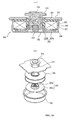
Fig. 3 shows diagrams showing an insulating cover of a contact device, wherein (a) is a perspective view, (b) is a plan view before mounting, and (c) is a plan view after mounting. - [
Fig. 4 ]
Fig. 4 is an illustration showing an insulating cover mounting method. - [
Fig. 5 ]
Fig. 5 is a sectional view along an A-A line inFig. 1 . - [
Fig. 6 ]
Fig. 6 is an illustration accompanying a description of arc extinguishing by an arc extinguishing permanent magnet according to the invention. - [
Fig. 7 ]
Fig. 7 is an illustration accompanying a description of arc extinguishing when the arc extinguishing permanent magnet is disposed on the outer side of an insulating case. - [
Fig. 8 ]
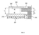
Fig. 8 is an enlarged sectional view showing the positional relationship between a permanent magnet and a movable plunger. - [
Fig. 9 ]
Fig. 9 shows diagrams illustrating an action of suctioning the movable plunger with the permanent magnet, wherein (a) is a partial sectional view showing a released condition and (b) is a partial sectional view showing an engaged condition. - [
Fig. 10 ]
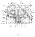
Fig. 10 is a sectional view showing a second embodiment of an electromagnetic contactor according to the invention. - [
Fig. 11 ]
Fig. 11 shows diagrams showing a modification example of the contact device of the invention, wherein (a) is a sectional view and (b) is a perspective view. - [
Fig. 12 ]
Fig. 12 shows diagrams showing another modification example of the contact device of the invention, wherein (a) is a sectional view and (b) is a perspective view. - [
Fig. 13 ]
Fig. 13 is an exploded perspective view showing a modification example of an insulating tubular body of the contact device. - [
Fig. 14 ]
Fig. 14 shows diagrams showing a modification example of a cylindrical auxiliary yoke of an electromagnet unit, wherein (a) is a sectional view and (b) is an exploded perspective view. - [
Fig. 15 ]
Fig. 15 shows diagrams showing a modification example of the cylindrical auxiliary yoke of the electromagnet unit, wherein (a) is a sectional view and (b) is an exploded perspective view. - Hereafter, a description will be given, based on the drawings, of embodiments of the invention.
-
Fig. 1 is a sectional view showing one example of an electromagnetic switch according to the invention, whileFig. 2 is an exploded perspective view of an arc extinguishing chamber. InFig. 1 andFig. 2 ,10 is an electromagnetic contactor, and theelectromagnetic contactor 10 is configured of acontact device 100 in which is disposed a contact mechanism, and anelectromagnet unit 200 that drives thecontact device 100. - The
contact device 100 has anarc extinguishing chamber 102 in which is housed acontact mechanism 101, as is clear fromFig. 1 andFig. 2 . Thearc extinguishing chamber 102, as shown inFig. 2(a) , includes a metal squaretubular body 104 having on a lower end portion ametal flange portion 103 protruding outward, and a fixed contactsupport insulating substrate 105 configured of a plate-like ceramic insulating substrate that closes off the upper end of the metal squaretubular body 104. - The metal square
tubular body 104 is such that theflange portion 103 thereof is seal joined to an upper portionmagnetic yoke 210 of theelectromagnet unit 200, to be described hereafter. - Also, through
holes contacts support insulating substrate 105. A metalizing process is performed around the throughholes support insulating substrate 105, and in a position on the lower surface side that comes into contact with the squaretubular body 104. To carry out the metalizing process, in a condition in which a plurality of fixed contactsupport insulating substrates 105 are arranged vertically and horizontally on a flat surface, a metal foil is formed around the throughholes tubular body 104. - The
contact mechanism 101, as shown inFig. 1 , includes the pair of fixedcontacts holes support insulating substrate 105 of thearc extinguishing chamber 102. Each of the fixedcontacts support conductor portion 114, having on an upper end a flange portion protruding outward, inserted into the throughholes support insulating substrate 105, and a C-shapedportion 115, the inner side of which is opened, linked to thesupport conductor portion 114 and disposed on the lower surface side of the fixed contactsupport insulating substrate 105. - The C-shaped
portion 115 is formed in a C-shape of anupper plate portion 116 extending to the outer side along the lower surface of the fixed contactsupport insulating substrate 105, anintermediate plate portion 117 extending downward from the outer side end portion of theupper plate portion 116, and alower plate portion 118 extending from the lower end side of theintermediate plate portion 117, parallel with theupper plate portion 116, to the inner side, that is, in a direction facing the fixedcontacts upper plate portion 116 is added to an L-shape formed by theintermediate plate portion 117 andlower plate portion 118. - Herein, the
support conductor portion 114 and C-shapedportion 115 are fixed by, for example, brazing in a condition in which apin 114a formed protruding on the lower end surface of thesupport conductor portion 114 is inserted into a throughhole 120 formed in theupper plate portion 116 of the C-shapedportion 115. The fixing of thesupport conductor portion 114 and C-shapedportion 115, not being limited to brazing, may be such that thepin 114a is fitted into the throughhole 120, or an external thread is formed on thepin 114a and an internal thread is formed in the throughhole 120, and the two are screwed together. - Also, a
magnetic plate 119 of a C-shape when seen in plan view is mounted so as to cover the inner side surface of theintermediate plate portion 117 in the C-shapedportion 115 of the fixedcontacts magnetic plate 119 so as to cover the inner side surface of theintermediate plate portion 117 in this way, it is possible to shield a magnetic field generated by current flowing through theintermediate plate portion 117. Because of this, in the event that an arc is generated when, from a condition in whichcontact portions 130a of amovable contact 130 are in contact withcontact portions 118a of the fixedcontacts contact portions 130a move away upward, as described hereafter, it is possible to prevent interference between a magnetic field caused by the current flowing through theintermediate plate portion 117 and a magnetic field caused by the arc generated between thecontact portions 118a of the fixedcontacts contact portions 130a of themovable contact 130. Consequently, it is possible to prevent the two magnetic fields from repelling each other, the arc being moved to the inner side along themovable contact 130 by this electromagnetic repulsion, and interruption of the arc becoming difficult. - Furthermore, an insulating
cover 121, made of a synthetic resin material, that regulates arc generation is mounted on the C-shapedportion 115 of each of the fixedcontacts cover 121 covers the inner peripheral surfaces of theupper plate portion 116 andintermediate plate portion 117 of the C-shapedportion 115, as shown inFigs. 3(a) and (b) . The insulatingcover 121 includes an L-shapedplate portion 122 that follows the inner peripheral surfaces of theupper plate portion 116 andintermediate plate portion 117,side plate portions plate portion 122, that cover side surfaces of theupper plate portion 116 andintermediate plate portion 117 of the C-shapedportion 115, and afitting portion 125, formed on the inward side from the upper end of theside plate portions small diameter portion 114b formed on thesupport conductor portion 114 of the fixedcontacts - Consequently, the insulating
cover 121 is placed in a condition in which thefitting portion 125 is facing thesmall diameter portion 114b of thesupport conductor portion 114 of the fixedcontacts Figs. 3(a) and (b) , after which, as shown inFig. 3(c) , thefitting portion 125 is fitted into thesmall diameter portion 114b of thesupport conductor portion 114 by pushing the insulatingcover 121. - Actually, with the
arc extinguishing chamber 102 after the fixedcontacts support insulating substrate 105 is on the lower side, the insulatingcover 121 is inserted from an upper aperture portion between the fixedcontacts Figs. 3(a) to (c) , as shown inFig. 4(a) . - Next, in a condition in which the
fitting portion 125 is in contact with the fixed contactsupport insulating substrate 105, as shown inFig. 4(b) , thefitting portion 125 is engaged with and fixed to thesmall diameter portion 114b of thesupport conductor portion 114 of the fixedcontacts cover 121 to the outer side, as shown inFig. 4(c) . - By mounting the insulating
cover 121 on the C-shapedportion 115 of the fixedcontacts lower plate portion 118 of the inner peripheral surface of the C-shapedportion 115 is exposed, and is taken to be thecontact portion 118a. - Further, the
movable contact 130 is disposed in such a way that both end portions are disposed in the C-shapedportion 115 of the fixedcontacts movable contact 130 is supported by a connectingshaft 131 fixed to amovable plunger 215 of theelectromagnet unit 200, to be described hereafter. Themovable contact 130 is such that, as shown inFig. 1 , a central portion in the vicinity of the connectingshaft 131 protrudes downward, whereby adepressed portion 132 is formed, and a throughhole 133 into which the connectingshaft 131 is inserted is formed in thedepressed portion 132. - A
flange portion 131a protruding outward is formed on the upper end of the connectingshaft 131. The connectingshaft 131 is inserted from the lower end side into acontact spring 134, then inserted into the throughhole 133 of themovable contact 130, bringing the upper end of thecontact spring 134 into contact with theflange portion 131a, and the movingcontact 130 is positioned using, for example, a C-ring 135 so as to obtain a predetermined biasing force from thecontact spring 134. - The
movable contact 130, in a released condition, takes on a condition wherein thecontact portions 130a at either end and thecontact portions 118a of thelower plate portions 118 of the C-shapedportions 115 of the fixedcontacts movable contact 130 is set so that, in an engaged position, the contact portions at either end come into contact with thecontact portions 118a of thelower plate portions 118 of the C-shapedportions 115 of the fixedcontacts contact spring 134. - Furthermore, an insulating
cylinder 140 made of, for example, a synthetic resin is disposed on the inner peripheral surface of the squaretubular body 104 of thearc extinguishing cylinder 102. The insulatingcylinder 140 is configured of a squaretubular portion 140a disposed on the inner peripheral surface of the squaretubular body 104 and a bottom plate portion 104b that closes off the lower surface side of the squaretubular portion 140a.Magnet housing pockets cylinder 140 facing the side surface of themovable contact 130, as shown inFig. 5 . Arc extinguishingpermanent magnets magnet housing pockets - The arc extinguishing
permanent magnets permanent magnets contact portions 118a of the fixedcontacts movable contact 130 are opposed, as shown inFig. 5 . Further,arc extinguishing spaces magnet housing pockets - Also, movable
contact guide members movable contact 130, are formed protruding, sliding against side edges of themagnet housing pockets movable contact 130. - By disposing the arc extinguishing
permanent magnets cylinder 140 in this way, it is possible to bring the arc extinguishingpermanent magnets movable contact 130. Because of this, as shown inFig. 6(a) , magnetic flux φ emanating from the N-pole sides of the two arc extinguishingpermanent magnets contact portions 118a of the fixedcontacts contact portions 130a of themovable contact 130 are opposed in a left-right direction, from the inner side to the outer side, with a large magnetic flux density. - Consequently, assuming that the fixed
contact 111 is connected to a current supply source and the fixedcontact 112 is connected to a load side, the current direction in the engaged condition is such that the current flows from the fixedcontact 111 through themovable contact 130 to the fixedcontact 112, as shown inFig. 6(b) . Then, when changing from the engaged condition to the released condition by causing themovable contact 130 to move away upward from the fixedcontacts contact portions 118a of the fixedcontacts contact portions 130a of themovable contact 130. - The arc is extended to the
arc extinguishing space 145 side on the arc extinguishingpermanent magnet 143 side by the magnetic flux φ from the arc extinguishingpermanent magnets arc extinguishing spaces permanent magnets - Incidentally, when the arc extinguishing
permanent magnets cylinder 140, as shown inFigs. 7(a) to 7(c) , there is an increase in the distance to the positions in which thecontact portions 118a of the fixedcontacts contact portions 130a of themovable contact 130 are opposed, and when the same permanent magnets as in this embodiment are applied, the density of the magnetic flux crossing the arc decreases. - Because of this, the Lorentz force acting on an arc generated when shifting from the engaged condition to the released condition decreases, and it is no longer possible to sufficiently extend the arc. In order to improve the arc extinguishing performance, it is necessary to increase the magnetization of the arc extinguishing
permanent magnets permanent magnets contacts movable contact 130, it is necessary to reduce the depth in a front-back direction of the insulatingcylinder 140, and there is a problem in that it is not possible to secure sufficient arc extinguishing space to extinguish the arc. - However, according to the heretofore described embodiment, the arc extinguishing
permanent magnets cylinder 140, meaning that the problems occurring when the arc extinguishingpermanent magnets cylinder 140 can all be solved. - The
electromagnet unit 200, as shown inFig. 1 , has amagnetic yoke 201 of a flattened U-shape when seen from the side, and a cylindricalauxiliary yoke 203 is fixed in a central portion of abottom plate portion 202 of themagnetic yoke 201. Aspool 204 is disposed on the outer side of the cylindricalauxiliary yoke 203. - The
spool 204 is configured of acentral cylinder portion 205 in which the cylindricalauxiliary yoke 203 is inserted, alower flange portion 206 protruding outward in a radial direction from a lower end portion of thecentral cylinder portion 205, and anupper flange portion 207 protruding outward in a radial direction from slightly below the upper end of thecentral cylinder portion 205. Further, anexciting coil 208 is mounted wound in a housing space configured of thecentral cylinder portion 205,lower flange portion 206, andupper flange portion 207. - Further, an upper
magnetic yoke 210 is fixed between upper ends forming an opened end of themagnetic yoke 201. A throughhole 210a opposing thecentral cylinder portion 205 of thespool 204 is formed in a central portion of the uppermagnetic yoke 210. - Further, the
movable plunger 215, in which is disposed areturn spring 214 between a bottom portion and thebottom plate portion 202 of themagnetic yoke 201, is disposed in thecentral cylinder portion 205 of thespool 204 so as to be able to slide up and down. Aperipheral flange portion 216 protruding outward in a radial direction is formed on themovable plunger 215, on an upper end portion protruding upward from the uppermagnetic yoke 210. - Also, a
permanent magnet 220 formed in a ring-form is fixed to the upper surface of the uppermagnetic yoke 210 so as to enclose theperipheral flange portion 216 of themovable plunger 215. Thepermanent magnet 220 has a throughhole 221 that encloses theperipheral flange portion 216. Thepermanent magnet 220 is magnetized in an up-down direction, that is, a thickness direction, so that, for example, the upper end side is an N-pole while the lower end side is an S-pole. Taking the form of the throughhole 221 of thepermanent magnet 220 to be a form tailored to the form of theperipheral flange portion 216, the form of the outer peripheral surface can be any form, such as a circle or a rectangle. - Further, an
auxiliary yoke 225 of the same external form as thepermanent magnet 220, and having a throughhole 224 with an inner diameter smaller than the outer diameter of theperipheral flange portion 216 of themovable plunger 215, is fixed to the upper end surface of thepermanent magnet 220. Theperipheral flange portion 216 of themovable plunger 215 is brought into contact with the lower surface of theauxiliary yoke 225. - Herein, a thickness T of the
permanent magnet 220 is set to a value (T = L + t) wherein a stroke L of themovable plunger 215 and a thickness t of theperipheral flange portion 216 of themovable plunger 215 are added together, as shown inFig. 8 . Consequently, the stroke L of themovable plunger 215 is regulated by the thickness T of thepermanent magnet 220. - Because of this, it is possible to reduce to a minimum the cumulative number of parts and form tolerance, which affect the stroke of the
movable plunger 215. Also, by determining the stroke L of themovable plunger 215 using only the thickness T of thepermanent magnet 220 and the thickness t of theperipheral flange portion 216, it is possible to minimize variation of the stroke L. In particular, this is more advantageous in the case of a small electromagnetic contactor in which the stroke is small. - Also, as the
permanent magnet 220 is formed in a ring-form, the number of parts decreases in comparison with a case in which two permanent magnets are disposed divided left and right, as described in, for example, PLT 2-91901, and a reduction in cost is achieved. Also, as theperipheral flange portion 216 of themovable plunger 215 is disposed in the vicinity of the inner peripheral surface of the throughhole 221 formed in thepermanent magnet 220, there is no waste in a closed circuit passing magnetic flux generated by thepermanent magnet 220, leakage flux decreases, and it is possible to use the magnetic force of the permanent magnet effectively. - The form of the
permanent magnet 220 not being limited to that heretofore described, it can also be formed in an annular form, or in other words, the external form can be any form provided that the inner peripheral surface is a cylindrical surface. - Also, the connecting
shaft 131 that supports themovable contact 130 is screwed to the upper end surface of themovable plunger 215. - Further, in the released condition, the
movable plunger 215 is biased upward by thereturn spring 214, and the upper surface of theperipheral flange portion 216 attains a released position wherein it is brought into contact with the lower surface of theauxiliary yoke 225. In this condition, thecontact portions 130a of themovable contact 130 have moved away upward from thecontact portions 118a of the fixedcontacts - In the released condition, the
peripheral flange portion 216 of themovable plunger 215 is suctioned to theauxiliary yoke 225 by the magnetic force of thepermanent magnet 220, and by a combination of this and the biasing force of thereturn spring 214, the condition in which themovable plunger 215 is brought into contact with theauxiliary yoke 225 is maintained, with no unplanned downward movement due to external vibration, shock, or the like. - Also, in the released condition, as shown in
Fig. 9(a) , relationships between a gap g1 between the lower surface of theperipheral flange portion 216 of themovable plunger 215 and the upper surface of the uppermagnetic yoke 210, a gap g2 between the outer peripheral surface of themovable plunger 215 and the throughhole 210a of the uppermagnetic yoke 210, a gap g3 between the outer peripheral surface of themovable plunger 215 and the cylindricalauxiliary yoke 203, and a gap g4 between the lower surface of themovable plunger 215 and the upper surface of thebottom plate portion 202 of themagnetic yoke 201 are set as below.
- Because of this, when exciting the
exciting coil 208 in the released condition, the magnetic flux passes from themovable plunger 215 through theperipheral flange portion 216, passes through the gap g1 between theperipheral flange portion 216 and uppermagnetic yoke 210, and reaches the uppermagnetic yoke 210, as shown inFig. 9(a) . A closed magnetic circuit is formed from the uppermagnetic yoke 210, through the U-shapedmagnetic yoke 201 and through the cylindricalauxiliary yoke 203, as far as themovable plunger 215. - Because of this, it is possible to increase the magnetic flux density of the gap g1 between the lower surface of the
peripheral flange portion 216 of themovable plunger 215 and the upper surface of the uppermagnetic yoke 210, a larger suctioning force is generated, and themovable plunger 215 is caused to descend against the biasing force of thereturn spring 214 and the suctioning force of thepermanent magnet 220. Consequently, thecontact portions 130a of themovable contact 130 connected to themovable plunger 215 via the connectingshaft 131 are brought into contact with thecontact portions 118a of the fixedcontacts contact 111, through themovable contact 130, toward the fixedcontact 112, creating the engaged condition. - As the lower end surface of the
movable plunger 215 nears thebottom plate portion 202 of the U-shapedmagnetic yoke 201 on the engaged condition being created, as shown inFig. 9(b) , the heretofore described gaps g1 to g4 are as below.
- Because of this, the magnetic flux generated by the
exciting coil 208 passes from themovable plunger 215 through theperipheral flange portion 216, and enters the uppermagnetic yoke 210 directly, as shown inFig. 9(b) , while a closed magnetic circuit is formed from the uppermagnetic yoke 210, through the U-shapedmagnetic yoke 201, returning from thebottom plate portion 202 of the U-shapedmagnetic yoke 201 directly to themovable plunger 215. - Because of this, a large suctioning force acts in the gap g1 and gap g4, and the
movable plunger 215 is held in the down position. Because of this, the condition wherein thecontact portions 130a of themovable contact 130 connected to themovable plunger 215 via the connecting shaft 213 are in contact with thecontact portions 118a of the fixedcontacts - Further, the
movable plunger 215 is covered with acap 230 formed in a bottomed tubular form made of a non-magnetic body, and a flange portion 231 formed extending outward in a radial direction on an opened end of thecap 230 is seal joined to the lower surface of the uppermagnetic yoke 210. By so doing, a hermetic receptacle, wherein thearc extinguishing chamber 102 andcap 230 are in communication via the throughhole 210a of the uppermagnetic yoke 210, is formed. Further, a gas such as hydrogen gas, nitrogen gas, a mixed gas of hydrogen and nitrogen, air, or SF6 is encapsulated inside the hermetic receptacle formed by thearc extinguishing chamber 102 andcap 230. - Next, a description will be given of an operation of the heretofore described embodiment.
- For now, it is assumed that the fixed
contact 111 is connected to, for example, a power supply source that supplies a large current, while the fixedcontact 112 is connected to a load. - In this condition, the
exciting coil 208 in theelectromagnet unit 200 is in a non-excited state, and there exists a released condition wherein no exciting force causing themovable plunger 215 to descend is being generated in theelectromagnet unit 200. In this released condition, themovable plunger 215 is biased in an upward direction away from the uppermagnetic yoke 210 by thereturn spring 214. Simultaneously with this, a suctioning force caused by the magnetic force of thepermanent magnet 220 acts on theauxiliary yoke 225, and theperipheral flange portion 216 of themovable plunger 215 is suctioned. Because of this, the upper surface of theperipheral flange portion 216 of themovable plunger 215 is brought into contact with the lower surface of theauxiliary yoke 225. - Because of this, the
contact portions 130a of thecontact mechanism 101movable contact 130 connected to themovable plunger 215 via the connectingshaft 131 are separated by a predetermined distance upward from thecontact portions 118a of the fixedcontacts contacts contact mechanism 101 is in a condition wherein the contacts are opened. - In this way, as the biasing force of the
return spring 214 and the suctioning force of the ring-formpermanent magnet 220 both act on themovable plunger 215 in the released condition, there is no unplanned downward movement of themovable plunger 215 due to external vibration, shock, or the like, and it is thus possible to reliably prevent malfunction. - On the
exciting coil 208 of theelectromagnet unit 200 being excited in the released condition, an exciting force is generated in theelectromagnet unit 200, and themovable plunger 215 is pressed downward against the biasing force of thereturn spring 214 and the suctioning force of the ring-formpermanent magnet 220. At this time, as shown inFig. 9(a) , the gap g4 between the bottom surface of themovable plunger 215 and thebottom plate portion 202 of themagnetic yoke 201 is large, and hardly any magnetic flux passes through the gap g4. - However, the cylindrical
auxiliary yoke 203 opposes the lower outer peripheral surface of themovable plunger 215, and the gap g3 between themovable plunger 215 and the cylindricalauxiliary yoke 203 is set to be smaller in comparison with the gap g4. Because of this, a magnetic path passing through the cylindricalauxiliary yoke 203 is formed between themovable plunger 215 and thebottom plate portion 202 of themagnetic yoke 201. - Furthermore, the gap g1 between the lower surface of the
peripheral flange portion 216 of themovable plunger 215 and the uppermagnetic yoke 210 is set to be smaller in comparison with the gap g2 between the outer peripheral surface of themovable plunger 215 and the inner peripheral surface of the throughhole 210a of the uppermagnetic yoke 210. Because of this, the magnetic flux density between the lower surface of theperipheral flange portion 216 of themovable plunger 215 and the upper surface of the uppermagnetic yoke 210 increases, and a large suctioning force acts, suctioning theperipheral flange portion 216 of themovable plunger 215. - Consequently, the
movable plunger 215 descends swiftly against the biasing force of thereturn spring 214 and the suctioning force of the ring-formpermanent magnet 220. Because of this, the descent of themovable plunger 215 is stopped by the lower surface of theperipheral flange portion 216 coming into contact with the upper surface of the uppermagnetic yoke 210, as shown inFig. 9(b) . - By the
movable plunger 215 descending in this way, themovable contact 130 connected to themovable plunger 215 via the connectingshaft 131 also descends, and thecontact portions 130a of themovable contact 130 come into contact with thecontact portions 118a of the fixedcontacts - Because of this, there exists a closed contact condition wherein the large current of the external power supply source is supplied via the fixed
contact 111,movable contact 130, and fixedcontact 112 to the load. - At this time, an electromagnetic repulsion force is generated between the fixed
contacts movable contact 130 in a direction such as to cause the contacts of themovable contact 130 to open. - However, as the fixed
contacts portion 115 is formed of theupper plate portion 116,intermediate plate portion 117, andlower plate portion 118, as shown inFig. 1 , the current in theupper plate portion 116 andlower plate portion 118 and the current in the opposingmovable contact 130 flow in opposite directions. Because of this, from the relationship between a magnetic field formed by thelower plate portions 118 of the fixedcontacts movable contact 130, it is possible, in accordance with Fleming's left-hand rule, to generate a Lorentz force that presses themovable contact 130 against thecontact portions 118a of the fixedcontacts - Because of this Lorentz force, it is possible to oppose the electromagnetic repulsion force generated in the contact opening direction between the
contact portions 118a of the fixedcontacts contact portions 130a of themovable contact 130, and thus possible to reliably prevent thecontact portions 130a of themovable contact 130 from opening. Because of this, it is possible to reduce the pressing force of thecontact spring 134 supporting themovable contact 130, and also possible to reduce thrust generated in theexciting coil 208 in response to the pressing force, and it is thus possible to reduce the size of the overall configuration of the electromagnetic contactor. - When interrupting the supply of current to the load in the closed contact condition of the
contact mechanism 101, the exciting of theexciting coil 208 of theelectromagnet unit 200 is stopped. - By so doing, the exciting force causing the
movable plunger 215 to move downward in theelectromagnet unit 200 stops, themovable plunger 215 is raised by the biasing force of thereturn spring 214, and the suctioning force of the ring-formpermanent magnet 220 increases as theperipheral flange portion 216 nears theauxiliary yoke 225. - By the
movable plunger 215 rising, themovable contact 130 connected via the connectingshaft 131 rises. As a result of this, themovable contact 130 is in contact with the fixedcontacts contact spring 134. Subsequently, there starts an opened contact condition, wherein themovable contact 130 moves upward away from the fixedcontacts contact spring 134 stops. - On the opened contact condition starting, an arc is generated between the
contact portions 118a of the fixedcontacts contact portions 130a of themovable contact 130, and the condition in which current is conducted is continued owing to the arc. At this time, as the insulatingcover 121 is mounted covering theupper plate portion 116 andintermediate plate portion 117 of the C-shapedportion 115 of the fixedcontacts contact portions 118a of the fixedcontacts contact portions 130a of themovable contact 130. Because of this, it is possible to stabilize the arc generation condition, and thus possible to improve arc extinguishing performance. - Also, as the
upper plate portion 116 andintermediate plate portion 117 of the C-shapedportion 115 are covered by the insulatingcover 121, it is possible to maintain insulating distance with the insulatingcover 121 between the two end portions of themovable contact 130 and theupper plate portion 116 andintermediate plate portion 117 of the C-shapedportion 115, and thus possible to reduce the height in the movable direction of themovable contact 130. Consequently, it is possible to reduce the size of thecontact device 100. - Furthermore, as the inner surface of the
intermediate plate portion 117 of the fixedcontacts magnetic plate 119, a magnetic field generated by current flowing through theintermediate plate portion 117 is shielded by themagnetic plate 119. Because of this, there is no interference between a magnetic field caused by the arc generated between thecontact portions 118a of the fixedcontacts contact portions 130a of themovable contact 130 and the magnetic field caused by the current flowing through theintermediate plate portion 117, and it is thus possible to prevent the arc from being affected by the magnetic field generated by the current flowing through theintermediate plate portion 117. - At this time, as the opposing magnetic pole faces of the arc extinguishing
permanent magnets Fig. 6(a) , crosses an arc generation portion of a portion in which thecontact portion 118a of the arc extinguishingpermanent magnets contact 111 and thecontact portion 130a of themovable contact 130 are opposed, from the inner side to the outer side in the longitudinal direction of themovable contact 130, and reaches the S-pole, whereby a magnetic field is formed. In the same way, the magnetic flux crosses an arc generation portion of thecontact portion 118a of the fixedcontact 112 and thecontact portion 130a of themovable contact 130, from the inner side to the outer side in the longitudinal direction of themovable contact 130, and reaches the S-pole, whereby a magnetic field is formed. - Consequently, the magnetic fluxes of the
arc extinguishing magnets contact portion 118a of the fixedcontact 111 and thecontact portion 130a of themovable contact 130 and between thecontact portion 118a of the fixedcontact 112 and thecontact portion 130a of themovable contact 130, in mutually opposite directions in the longitudinal direction of themovable contact 130. - Because of this, a current I flows from the fixed
contact 111 side to themovable contact 130 side between thecontact portion 118a of the fixedcontact 111 and thecontact portion 130a of themovable contact 130, and the orientation of the magnetic flux φ is in a direction from the inner side toward the outer side, as shown inFig. 6(b) . Because of this, in accordance with Fleming's left-hand rule, a large Lorentz force F acts toward thearc extinguishing space 145 side, perpendicular to the longitudinal direction of themovable contact 130 and perpendicular to the switching direction of thecontact portion 118a of the fixedcontact 111 and themovable contact 130, as shown inFig. 6(c) . - Owing to the Lorentz force F, an arc generated between the
contact portion 118a of the fixedcontact 111 and thecontact portion 130a of themovable contact 130 is greatly extended so as to pass from the side surface of thecontact portion 118a of the fixedcontact 111 through the inside of thearc extinguishing space 145, reaching the upper surface side of themovable contact 130, and is extinguished. - Also, at the lower side and upper side of the
arc extinguishing space 145, magnetic flux inclines to the lower side and upper side with respect to the orientation of the magnetic flux between thecontact portion 118a of the fixedcontact 111 and thecontact portion 130a of themovable contact 130. Because of this, the arc extended to thearc extinguishing space 145 is further extended by the inclined magnetic flux in the direction of the corner of thearc extinguishing space 145, it is possible to increase the arc length, and thus possible to obtain good interruption performance. - Meanwhile, the current I flows from the
movable contact 130 side to the fixedcontact 112 side between thecontact portion 118a of the fixedcontact 112 and themovable contact 130, and the orientation of the magnetic flux φ is in a rightward direction from the inner side toward the outer side, as shown inFig. 6(b) . Because of this, in accordance with Fleming's left-hand rule, a large Lorentz force F acts toward thearc extinguishing space 145, perpendicular to the longitudinal direction of themovable contact 130 and perpendicular to the switching direction of thecontact portion 118a of the fixedcontact 112 and themovable contact 130. - Owing to the Lorentz force F, an arc generated between the
contact portion 118a of the fixedcontact 112 and themovable contact 130 is greatly extended so as to pass from the upper surface side of themovable contact 130 through the inside of thearc extinguishing space 145, reaching the side surface side of the fixedcontact 112, and is extinguished. - Also, at the lower side and upper side of the
arc extinguishing space 145, as heretofore described, magnetic flux inclines to the lower side and upper side with respect to the orientation of the magnetic flux between thecontact portion 118a of the fixedcontact 112 and thecontact portion 130a of themovable contact 130. Because of this, the arc extended to thearc extinguishing space 145 is further extended by the inclined magnetic flux in the direction of the corner of thearc extinguishing space 145, it is possible to increase the arc length, and thus possible to obtain good interruption performance. - Meanwhile, in the engaged condition of the
electromagnetic contactor 10, when adopting a released condition in a condition wherein a regenerative current flows from the load side to the direct current power source side, the direction of current inFig. 6(b) is reversed, meaning that the Lorentz force F acts on thearc extinguishing space 146 side, and excepting that the arc is extended to thearc extinguishing space 146 side, the same arc extinguishing function is fulfilled. - At this time, as the arc extinguishing
permanent magnets magnet housing pockets cylinder 140, the arc does not come into direct contact with the arc extinguishingpermanent magnets permanent magnets - Also, as it is possible to cover and insulate the inner peripheral surface of the metal square
tubular body 104 with the insulatingcylinder 140, there is no short circuiting of the arc when the current is interrupted, and it is thus possible to reliably carry out current interruption. - Furthermore, as it is possible to carry out the insulating function, the function of positioning the arc extinguishing
permanent magnets permanent magnets cylinder 140, it is possible to reduce manufacturing cost. - Also, as the movable
contact guide members magnet housing pockets permanent magnets movable contact 130, it is possible to reliably prevent turning of themovable contact 130. - In this way, according to the embodiment, as the C-shaped
portions 115 of the fixedcontacts contact spring 134 that provides contact pressure to themovable contact 130 are disposed in parallel in thecontact device 100, it is possible to reduce the height of thecontact mechanism 101 in comparison with a case wherein the fixed contacts, movable contact, and contact spring are disposed in series, as described in PLT 1. Because of this, it is possible to reduce the size of thecontact device 100. - Also, as the
arc extinguishing chamber 102 is formed by brazing the squaretubular body 104 and the plate-like fixed contactsupport insulating substrate 105, which closes off the upper plane of the squaretubular body 104 and in which the fixedcontacts support insulating substrates 105 closely together, on the same plane, vertically and horizontally, possible to carry out a metalizing process on a plurality of fixed contactsupport insulating substrates 105 at one time, and thus possible to improve productivity. - Also, as it is possible to braze the fixed contact
support insulating substrate 105 to the squaretubular body 104 after brazing and supporting the fixedcontacts support insulating substrate 105, it is possible to easily carry out the fixing and holding of the fixedcontacts - Control and management of the flatness and warpage of the fixed contact
support insulating substrate 105 are also easier in comparison with a case wherein thearc extinguishing chamber 102 is formed in a tub-form. Furthermore, it is possible to fabricate a large number of thearc extinguishing chambers 102 at one time, and thus possible to reduce the cost of fabrication. - Also, with regard to the
electromagnet unit 200, as the ring-formpermanent magnet 220 magnetized in the movable direction of themovable plunger 215 is disposed on the uppermagnetic yoke 210, and theauxiliary yoke 225 is formed on the upper surface of the ring-formpermanent magnet 220, it is possible to generate suctioning force to suction theperipheral flange portion 216 of themovable plunger 215 with the one ring-formpermanent magnet 220. - Because of this, it is possible to carry out the fixing of the
movable plunger 215 in the released condition with the magnetic force of the ring-formpermanent magnet 220 and the biasing force of thereturn spring 214, meaning that it is possible to improve holding force with respect to malfunction shock. - Also, it is possible to reduce the biasing force of the
return spring 214, and thus possible to reduce the total load of thecontact spring 134 and returnspring 214. Consequently, it is possible to reduce the suctioning force generated by theexciting coil 208 in accordance with the amount by which the total load is reduced, and thus possible to reduce the magnetomotive force of theexciting coil 208. Because of this, it is possible to reduce the shaft direction length of thespool 204, and thus possible to reduce the movable direction height of themovable plunger 215 of theelectromagnet unit 200. - In this way, as it is possible to reduce the movable direction height of the
movable plunger 215 in both thecontact device 100 andelectromagnet unit 200, it is possible to considerably shorten the overall configuration of theelectromagnetic contactor 10 in comparison with that of the heretofore known example described in PLT 1, and thus possible to achieve a reduction in size. - Furthermore, by disposing the
peripheral flange portion 216 of themovable plunger 215 inside the inner peripheral surface of the ring-formpermanent magnet 220, there is no waste in the closed circuit passing magnetic flux generated by the ring-formpermanent magnet 220, leakage flux decreases, and it is possible to use the magnetic force of the permanent magnet effectively. - Also, as the
peripheral flange portion 216 of themovable plunger 215 is disposed between the uppermagnetic yoke 210 and theauxiliary yoke 225 formed on the upper surface of the ring-formpermanent magnet 220, it is possible to regulate the stroke of themovable plunger 215 with the thickness of the ring-formpermanent magnet 220 and the thickness of theperipheral flange portion 216 of themovable plunger 215. - Because of this, it is possible to reduce to a minimum the cumulative number of parts and form tolerance, which affect the stroke of the
movable plunger 215. Moreover, by carrying out the regulation of the stroke of themovable plunger 215 using only the thickness of the ring-formpermanent magnet 220 and the thickness of theperipheral flange portion 216 of themovable plunger 215, it is possible to minimize variation of the stroke. - Next, a description will be given, based on
Fig. 10 , of a second embodiment of the invention. - In the second embodiment, the configuration of the arc extinguishing chamber is changed.
- That is, in the second embodiment, as shown in
Fig. 10 andFig. 2(b) , a squaretubular portion 301 and an uppersurface plate portion 302 closing off the upper end of the squaretubular portion 301 are formed integrally of a ceramic or a synthetic resin material, forming a tub-form body 303, a metal foil is formed on an opened end surface side of the tub-form body 303 by a metalizing process, and ametal connection member 304 is seal joined to the metal foil, configuring thearc extinguishing chamber 102. - Further, a
bottom plate portion 305, corresponding to the bottom plate portion 104b in the first embodiment, formed of, for example, a synthetic resin is disposed on the inner peripheral surface on the bottom surface side of the tub-form body 303. - Also, through
holes contacts surface plate portion 302, in the same way as in the fixed contactsupport insulating substrate 105, and the fixedcontacts holes - Other configurations have the same configuration as in the first embodiment, portions corresponding to those in
Fig. 1 are given the same reference signs, and a detailed description thereof is omitted. - According to the second embodiment, as the
arc extinguishing chamber 102 is configured of the tub-form body 303 integrally formed of an insulating material, it is possible to easily form the air tightarc extinguishing chamber 102 in a small number of man hours, and it is possible to reduce the number of parts. - In the first and second embodiments, a description has been given of a case wherein the C-shaped
portion 115 is formed in the fixedcontacts portion 160, of a form such that theupper plate portion 116 of the C-shapedportion 115 is omitted, may be connected to thesupport conductor portion 114, as shown inFigs. 11(a) and (b) . - In this case too, in the closed contact condition wherein the
movable contact 130 is brought into contact with the fixedcontacts portion 160 to act on portions in which the fixedcontacts movable contact 130 are in contact. Because of this, it is possible to increase the magnetic flux density in the portions in which the fixedcontacts movable contact 130 are in contact, generating a Lorentz force that opposes the electromagnetic repulsion force. - Also, in the first and second embodiments, a description has been given of a case wherein the
movable contact 130 has adepressed portion 132 in a central portion thereof but, not being limited to this, thedepressed portion 132 may be omitted, forming a flat plate, as shown inFigs. 12(a) and (b) . - Also, in the first and second embodiments, a description has been given of a case wherein the insulating
cylinder 140 that holds the arc extinguishingpermanent magnets - That is, as shown in
Fig. 13 , the insulatingcylinder 140 may be formed by disposing an assembly of fourside plate portions 256 to 259 configuring side walls on front and back and left and right end portions of abottom plate portion 253 on which is formed amagnet housing portion 252 of abase member 251, and connecting theside plate portions 256 to 259. In this case, as the side wall portion is divided into the fourside plate portions 256 to 259, manufacture is easier compared with the case in which the whole is formed integrally. Furthermore, a square tubular body wherein the fourside plate portions 256 to 259 are integrated may also be formed. - Also, in the first and second embodiments, a description has been given of a case wherein the connecting
shaft 131 is screwed to themovable plunger 215, but themovable plunger 215 and connectingshaft 131 may also be formed integrally. Also, a description has been given of a case wherein the connection of the connectingshaft 131 andmovable contact 130 is such that theflange portion 131a is formed on the leading end portion of the connectingshaft 131, and the lower end of themovable contact 130 is fixed with a C-ring after the connectingshaft 131 is inserted into thecontact spring 134 andmovable contact 130, but not being limited to this. That is, a positioning large diameter portion may be formed protruding in a radial direction in the C-ring position of the connectingshaft 131, thecontact spring 134 may be disposed after themovable contact 130 is brought into contact with the large diameter portion, and the upper end of thecontact spring 134 may be fixed with the C-ring. - Also, in the first and second embodiments, a description has been given of a case wherein the cylindrical
auxiliary yoke 203 is disposed in proximity to the lower end side of themovable plunger 215, but not being limited to this. That is, as shown inFigs. 14(a) and (b) , themagnetic yoke 201 may be formed in a bottomed cylindrical form, and theauxiliary yoke 203 may be configured of anannular plate portion 203a along thebottom plate portion 202 of themagnetic yoke 201 and acylinder portion 203b rising upward from the inner peripheral surface of theannular plate portion 203a. - Also, as shown in
Figs. 15(a) and (b) , a throughhole 202a may be formed in thebottom plate portion 202 of the U-shapedmagnetic yoke 210, the protruding form of theauxiliary yoke 203 may be fitted inside the throughhole 202a, and asmall diameter portion 203c of theauxiliary yoke 203 may be inserted into aninsertion hole 217 formed in themovable plunger 215. - Also, in the embodiments, a description has been given of a case wherein a hermetic receptacle is configured of the
arc extinguishing chamber 102 andcap 230, and gas is encapsulated inside the hermetic receptacle but, not being limited to this, the gas encapsulation may be omitted when the interrupted current is small. - 10 ... Electromagnetic contactor, 11 ... External insulating receptacle, 100 ... Contact device, 101 ... Contact mechanism, 102 ... Arc extinguishing chamber, 104 ... Square tubular body, 105 ... Fixed contact support insulating substrate, 111, 112 ... Fixed contact, 114 ... Support conductor portion, 115 ... C-shaped portion, 116 ... Upper plate portion, 117 ... Intermediate plate portion, 118 ... Lower plate portion, 118a ... Contact portion, 121 ... Insulating cover, 122 ... L-shaped plate portion, 123, 124 ... Side plate portion, 125 ... Fitting portion, 130 ... Movable contact, 130a ... Contact portion, 131 ... Connecting shaft, 132 ... Depressed portion, 134 ... Contact spring, 140 ... Insulating cylinder, 141, 142 ... Magnet housing pocket, 143, 144 ... Arc extinguishing permanent magnet, 145, 146 ... Arc extinguishing space, 160 ... L-shaped portion, 200 ... Electromagnet unit, 201 ... Magnetic yoke, 203 ... Cylindrical auxiliary yoke, 204 ... Spool, 208 ... Exciting coil, 210 ... Upper magnetic yoke, 214 ... Return spring, 215 ... Movable plunger, 216 ... Peripheral flange portion, 220 ... Permanent magnet, 225 ... Auxiliary yoke, 251 ... Base member, 252 ... Insulating square tubular body, 254, 255 ... Magnet housing square tubular portion, 301 ... Square tubular portion, 302 ... Upper surface plate portion, 303 ... Tub-form body, 304 ... Connection member, 305 ... Bottom plate portion
Claims (7)
- An electromagnetic contactor, characterized by including:a contact device in which are installed a pair of fixed contacts and a movable contact disposed so as to be connectable to and detachable from the pair of fixed contacts; andan electromagnet unit including an exciting coil that drives a movable plunger connected via a connecting shaft to the movable contact of the contact device, whereinthe contact device has a configuration such that L-shaped portions having a contact portion and extending to a predetermined length in mutually facing directions are formed in the pair of fixed contacts disposed and fixed maintaining a predetermined interval, and the two ends of the movable contact are disposed so as to be connectable to and detachable from the contact portions of the L-shaped portion on the side opposite to that of the electromagnet unit, andthe electromagnet unit includes a magnetic yoke enclosing a plunger drive portion, a movable plunger whose leading end protrudes through an aperture formed in the magnetic yoke and which is biased by a return spring, and a ring-form permanent magnet, magnetized in the movable direction of the movable plunger, disposed andfixed so as to enclose a peripheral flange portion formed on the protruding end side of the movable plunger.
- The electromagnetic contactor according to claim 1, characterized in that the pair of fixed contacts is such that the L-shaped portion is modified to a C-shaped portion by forming opposing plate portions in positions such as to face each other from either side of the two ends of the movable contact, and an insulating cover that regulates arc generation is mounted on inner peripheral portions of the C-shaped portion other than the contact portion.
- The electromagnetic contactor according to claim 1, characterized in that the contact device has a configuration such that the pair of fixed contacts and the movable contact are enclosed in a contact housing case, and an arc extinguishing permanent magnet is disposed along the movable contact on the inner peripheral surface side of the contact housing case.
- The electromagnetic contactor according to claim 3, characterized in that the contact housing case is configured of a metal tubular body, one end of which is hermetically sealed to an upper magnetic yoke of the electromagnet unit, enclosing the pair of fixed contacts and the movable contact, a fixed contact support insulating substrate joined hermetically closing off an opened end surface of the metal tubular body and supporting the pair of fixed contacts, and an insulating tubular body disposed on the inner peripheral surface of the metal tubular body.
- The electromagnetic contactor according to any one of claims 1 to 4, characterized in that
the movable contact is disposed so as to be movable via a contact spring in the flange portion formed on the leading end of the connecting shaft connected to the movable plunger, and a central portion supported by the connecting shaft and receiving the contact spring is a depressed portion protruding on the electromagnet unit side. - The electromagnetic contactor according to any one of claims 1 to 4, characterized in that
the electromagnet unit includes a magnetic yoke of a U-shape in cross-section whose upper portion is opened, an upper magnetic yoke bridging the upper opened portion of the magnetic yoke, a spool disposed on a bottom surface plate portion of the magnetic yoke and having a central aperture in which an exciting coil is wound, a movable plunger, disposed in the central aperture of the spool so as to be movable in an axial direction, whose leading end protrudes through an aperture formed in the upper magnetic yoke and which is biased by a return spring, a ring-form permanent magnet, disposed and fixed on the upper magnetic yoke so as to enclose a peripheral flange portion formed on the leading end side of the movable plunger, and magnetized in an axial direction, and an auxiliary yoke fixed on the upper surface of the ring-form permanent magnet and in contact with the peripheral flange portion of the movable plunger on the side opposite to that of the upper magnetic yoke. - The electromagnetic contactor according to claim 6, characterized in that the electromagnet unit includes a ring-form auxiliary yoke that encloses side surfaces of a bottom surface side end portion of the U-shaped magnetic yoke of the movable plunger in a released position, wherein the length of a gap between the ring-form auxiliary yoke and the side surface of the movable plunger is set to be less than the length of a gap between the bottom surface side end portion of the movable plunger and the U-shaped magnetic yoke.
Applications Claiming Priority (2)
| Application Number | Priority Date | Filing Date | Title |
|---|---|---|---|
| JP2011112912A JP5684649B2 (en) | 2011-05-19 | 2011-05-19 | Magnetic contactor |
| PCT/JP2012/002330 WO2012157173A1 (en) | 2011-05-19 | 2012-04-03 | Electromagnetic contactor |
Publications (3)
| Publication Number | Publication Date |
|---|---|
| EP2711963A1 true EP2711963A1 (en) | 2014-03-26 |
| EP2711963A4 EP2711963A4 (en) | 2015-03-18 |
| EP2711963B1 EP2711963B1 (en) | 2016-02-24 |
Family
ID=47176528
Family Applications (1)
| Application Number | Title | Priority Date | Filing Date |
|---|---|---|---|
| EP12785581.5A Not-in-force EP2711963B1 (en) | 2011-05-19 | 2012-04-03 | Electromagnetic contactor |
Country Status (5)
| Country | Link |
|---|---|
| US (1) | US8823472B2 (en) |
| EP (1) | EP2711963B1 (en) |
| JP (1) | JP5684649B2 (en) |
| CN (1) | CN103238198B (en) |
| WO (1) | WO2012157173A1 (en) |
Families Citing this family (30)
| Publication number | Priority date | Publication date | Assignee | Title |
|---|---|---|---|---|
| WO2011115054A1 (en) | 2010-03-15 | 2011-09-22 | オムロン株式会社 | Coil terminal |
| JP5884034B2 (en) * | 2011-03-22 | 2016-03-15 | パナソニックIpマネジメント株式会社 | Contact device |
| JP5778989B2 (en) * | 2011-05-19 | 2015-09-16 | 富士電機機器制御株式会社 | Magnetic contactor |
| JP5864902B2 (en) * | 2011-05-19 | 2016-02-17 | 富士電機機器制御株式会社 | Assembling method of arc extinguishing chamber of magnetic contactor |
| WO2012165433A1 (en) * | 2011-05-31 | 2012-12-06 | オムロン株式会社 | Electromagnetic relay |
| JP2014072061A (en) * | 2012-09-28 | 2014-04-21 | Panasonic Corp | Electric connector for electric vehicle |
| CN103915290A (en) * | 2013-01-09 | 2014-07-09 | 厦门宏发电力电器有限公司 | Magnetic latching relay of directly-operated type magnetic circuit structure |
| CN103730273A (en) * | 2013-12-20 | 2014-04-16 | 吴江市东泰电力特种开关有限公司 | Double-acting power switch |
| CN103730275A (en) * | 2013-12-20 | 2014-04-16 | 吴江市东泰电力特种开关有限公司 | Rotating contact arc extinguishing chamber |
| CN105428161A (en) * | 2014-09-03 | 2016-03-23 | 苏州磁明科技有限公司 | Electromechanical lockable relay and use method thereof |
| JP6528271B2 (en) | 2015-04-13 | 2019-06-12 | パナソニックIpマネジメント株式会社 | Contact device and electromagnetic relay |
| JP6558571B2 (en) * | 2015-07-01 | 2019-08-14 | パナソニックIpマネジメント株式会社 | Electromagnetic relay |
| JP6582913B2 (en) * | 2015-11-19 | 2019-10-02 | 富士電機機器制御株式会社 | Magnetic contactor |
| JP6274229B2 (en) * | 2016-01-27 | 2018-02-07 | 富士電機機器制御株式会社 | Contact device and electromagnetic contactor using the same |
| JP6536472B2 (en) * | 2016-04-28 | 2019-07-03 | 株式会社デンソー | solenoid |
| CN105895452B (en) * | 2016-05-27 | 2017-11-10 | 浙江英洛华新能源科技有限公司 | Closed type HVDC relay |
| JP6648683B2 (en) * | 2016-12-26 | 2020-02-14 | アンデン株式会社 | Electromagnetic relay |
| CN107331583A (en) * | 2017-08-15 | 2017-11-07 | 昆山国力源通新能源科技有限公司 | Nonpolarity high-voltage DC contactor arc quenching system structure |
| US10855158B2 (en) * | 2018-04-19 | 2020-12-01 | Watasensor, Inc. | Magnetic power generation |
| JP6726869B2 (en) * | 2019-04-24 | 2020-07-22 | パナソニックIpマネジメント株式会社 | Contact device and electromagnetic relay |
| CN112151310B (en) * | 2019-06-26 | 2025-03-18 | 上海良信电器股份有限公司 | A moving contact assembly of a DC contactor and the DC contactor |
| JP7380175B2 (en) * | 2019-12-19 | 2023-11-15 | オムロン株式会社 | electromagnetic relay |
| JP2021118111A (en) * | 2020-01-27 | 2021-08-10 | 富士電機機器制御株式会社 | Electromagnetic contactor |
| JP7435487B2 (en) * | 2021-01-22 | 2024-02-21 | 富士電機機器制御株式会社 | Sealed magnetic contactor |
| CN117912892A (en) * | 2022-10-12 | 2024-04-19 | 厦门宏发电力电器有限公司 | Relay |
| KR20240051061A (en) | 2022-10-12 | 2024-04-19 | 샤먼 홍파 일렉트릭 파워 컨트롤즈 컴퍼니 리미티드 | Relay |
| CN118800619A (en) | 2023-04-11 | 2024-10-18 | 厦门宏发电力电器有限公司 | Relay |
| CN220272392U (en) * | 2023-06-26 | 2023-12-29 | 宁波联达绞盘有限公司 | Intelligent contactor |
| US12494333B2 (en) * | 2023-08-09 | 2025-12-09 | Sensata Technologies, Inc. | Fault breaking contactor with dynamic air gap mechanism |
| CN117198814A (en) * | 2023-10-23 | 2023-12-08 | 厦门宏发电力电器有限公司 | Magnetic latching relay |
Family Cites Families (25)
| Publication number | Priority date | Publication date | Assignee | Title |
|---|---|---|---|---|
| JP3321963B2 (en) * | 1994-02-22 | 2002-09-09 | 株式会社デンソー | Plunger type electromagnetic relay |
| JP3107288B2 (en) * | 1996-03-26 | 2000-11-06 | 松下電工株式会社 | Sealed contact device |
| DE19720858A1 (en) * | 1997-05-17 | 1998-11-19 | Smb Schwede Maschinenbau Gmbh | Electromagnetic actuator |
| DE10116505B4 (en) * | 2001-04-03 | 2005-04-14 | Bruker Biospin Gmbh | Integral passive shim system and method for a magnetic resonance apparatus |
| JP2004071512A (en) * | 2002-08-09 | 2004-03-04 | Omron Corp | Switchgear |
| JP3985628B2 (en) * | 2002-08-09 | 2007-10-03 | オムロン株式会社 | Switchgear |
| JP2004311389A (en) * | 2003-02-21 | 2004-11-04 | Sumitomo Electric Ind Ltd | DC relay |
| JP4321256B2 (en) | 2003-12-22 | 2009-08-26 | オムロン株式会社 | Electromagnetic relay |
| JP4375012B2 (en) * | 2003-12-22 | 2009-12-02 | オムロン株式会社 | Support structure for fixed contact terminals |
| JP4325393B2 (en) * | 2003-12-22 | 2009-09-02 | オムロン株式会社 | Switchgear |
| JP4466421B2 (en) * | 2005-03-18 | 2010-05-26 | パナソニック電工株式会社 | Sealed contact device |
| KR100845539B1 (en) * | 2005-03-28 | 2008-07-10 | 마츠시다 덴코 가부시키가이샤 | Contact device |
| JP2007305468A (en) * | 2006-05-12 | 2007-11-22 | Omron Corp | Electromagnetic relay |
| JP4765761B2 (en) * | 2006-05-12 | 2011-09-07 | オムロン株式会社 | Electromagnetic relay |
| EP2054908A1 (en) * | 2006-08-21 | 2009-05-06 | Arcoline Ltd. | Medium-voltage circuit-breaker |
| US7852178B2 (en) * | 2006-11-28 | 2010-12-14 | Tyco Electronics Corporation | Hermetically sealed electromechanical relay |
| KR20090119276A (en) * | 2008-05-15 | 2009-11-19 | 엘에스산전 주식회사 | Low noise electronic switch and its manufacturing method |
| JP5163317B2 (en) * | 2008-06-30 | 2013-03-13 | オムロン株式会社 | Contact device |
| JP5206157B2 (en) * | 2008-06-30 | 2013-06-12 | オムロン株式会社 | Electromagnetic relay |
| JP5163318B2 (en) * | 2008-06-30 | 2013-03-13 | オムロン株式会社 | Electromagnet device |
| JP5195144B2 (en) * | 2008-08-07 | 2013-05-08 | 株式会社デンソー | Electromagnetic switch |
| KR101004465B1 (en) * | 2008-09-05 | 2010-12-31 | 엘에스산전 주식회사 | relay |
| JP2010192416A (en) * | 2009-01-21 | 2010-09-02 | Panasonic Electric Works Co Ltd | Sealed contact device |
| JP5197480B2 (en) * | 2009-05-14 | 2013-05-15 | 株式会社日本自動車部品総合研究所 | Electromagnetic relay |
| JP5437949B2 (en) * | 2010-08-11 | 2014-03-12 | 富士電機機器制御株式会社 | Contact device and electromagnetic contactor using the same |
-
2011
- 2011-05-19 JP JP2011112912A patent/JP5684649B2/en active Active
-
2012
- 2012-04-03 EP EP12785581.5A patent/EP2711963B1/en not_active Not-in-force
- 2012-04-03 WO PCT/JP2012/002330 patent/WO2012157173A1/en not_active Ceased
- 2012-04-03 CN CN201280003642.6A patent/CN103238198B/en active Active
- 2012-04-03 US US13/885,094 patent/US8823472B2/en not_active Expired - Fee Related
Also Published As
| Publication number | Publication date |
|---|---|
| JP5684649B2 (en) | 2015-03-18 |
| WO2012157173A1 (en) | 2012-11-22 |
| EP2711963B1 (en) | 2016-02-24 |
| JP2012243589A (en) | 2012-12-10 |
| CN103238198A (en) | 2013-08-07 |
| US20130257567A1 (en) | 2013-10-03 |
| EP2711963A4 (en) | 2015-03-18 |
| CN103238198B (en) | 2016-08-03 |
| US8823472B2 (en) | 2014-09-02 |
Similar Documents
| Publication | Publication Date | Title |
|---|---|---|
| EP2711963B1 (en) | Electromagnetic contactor | |
| EP2711965B1 (en) | Electromagnetic contactor | |
| US9514896B2 (en) | Electromagnetic contactor | |
| EP2711956B1 (en) | Electromagnetic contactor | |
| US9117611B2 (en) | Electromagnetic contactor | |
| US9202652B2 (en) | Electromagnetic contactor | |
| US8836456B2 (en) | Electromagnetic contactor | |
| EP2711962A1 (en) | Electromagnetic contactor | |
| US9653222B2 (en) | Contact device, and electromagnetic switch in which the contact device is used | |
| EP2860748A1 (en) | Electromagnetic contactor | |
| EP2711954B1 (en) | Electromagnetic contactor | |
| EP2843682B1 (en) | Electromagnetic contactor | |
| US9589739B2 (en) | Electromagnetic contactor |
Legal Events
| Date | Code | Title | Description |
|---|---|---|---|
| PUAI | Public reference made under article 153(3) epc to a published international application that has entered the european phase |
Free format text: ORIGINAL CODE: 0009012 |
|
| 17P | Request for examination filed |
Effective date: 20130514 |
|
| AK | Designated contracting states |
Kind code of ref document: A1 Designated state(s): AL AT BE BG CH CY CZ DE DK EE ES FI FR GB GR HR HU IE IS IT LI LT LU LV MC MK MT NL NO PL PT RO RS SE SI SK SM TR |
|
| DAX | Request for extension of the european patent (deleted) | ||
| A4 | Supplementary search report drawn up and despatched |
Effective date: 20150212 |
|
| RIC1 | Information provided on ipc code assigned before grant |
Ipc: H01H 50/42 20060101ALI20150206BHEP Ipc: H01H 50/38 20060101AFI20150206BHEP Ipc: H01H 50/22 20060101ALN20150206BHEP |
|
| GRAP | Despatch of communication of intention to grant a patent |
Free format text: ORIGINAL CODE: EPIDOSNIGR1 |
|
| INTG | Intention to grant announced |
Effective date: 20150918 |
|
| RIC1 | Information provided on ipc code assigned before grant |
Ipc: H01H 50/38 20060101AFI20150907BHEP Ipc: H01H 50/22 20060101ALN20150907BHEP Ipc: H01H 50/42 20060101ALI20150907BHEP |
|
| RIN1 | Information on inventor provided before grant (corrected) |
Inventor name: TAKAYA, KOUETSU Inventor name: YAMAMOTO, YUICHI Inventor name: SHIBA, YUJI Inventor name: SUZUKI, KENJI Inventor name: NAKA, YASUHIRO |
|
| GRAS | Grant fee paid |
Free format text: ORIGINAL CODE: EPIDOSNIGR3 |
|
| GRAA | (expected) grant |
Free format text: ORIGINAL CODE: 0009210 |
|
| AK | Designated contracting states |
Kind code of ref document: B1 Designated state(s): AL AT BE BG CH CY CZ DE DK EE ES FI FR GB GR HR HU IE IS IT LI LT LU LV MC MK MT NL NO PL PT RO RS SE SI SK SM TR |
|
| REG | Reference to a national code |
Ref country code: GB Ref legal event code: FG4D |
|
| REG | Reference to a national code |
Ref country code: CH Ref legal event code: EP |
|
| REG | Reference to a national code |
Ref country code: AT Ref legal event code: REF Ref document number: 777111 Country of ref document: AT Kind code of ref document: T Effective date: 20160315 |
|
| REG | Reference to a national code |
Ref country code: IE Ref legal event code: FG4D |
|
| REG | Reference to a national code |
Ref country code: DE Ref legal event code: R096 Ref document number: 602012014989 Country of ref document: DE |
|
| REG | Reference to a national code |
Ref country code: FR Ref legal event code: PLFP Year of fee payment: 5 |
|
| REG | Reference to a national code |
Ref country code: LT Ref legal event code: MG4D |
|
| REG | Reference to a national code |
Ref country code: NL Ref legal event code: MP Effective date: 20160224 |
|
| REG | Reference to a national code |
Ref country code: AT Ref legal event code: MK05 Ref document number: 777111 Country of ref document: AT Kind code of ref document: T Effective date: 20160224 |
|
| PG25 | Lapsed in a contracting state [announced via postgrant information from national office to epo] |
Ref country code: FI Free format text: LAPSE BECAUSE OF FAILURE TO SUBMIT A TRANSLATION OF THE DESCRIPTION OR TO PAY THE FEE WITHIN THE PRESCRIBED TIME-LIMIT Effective date: 20160224 Ref country code: IT Free format text: LAPSE BECAUSE OF FAILURE TO SUBMIT A TRANSLATION OF THE DESCRIPTION OR TO PAY THE FEE WITHIN THE PRESCRIBED TIME-LIMIT Effective date: 20160224 Ref country code: HR Free format text: LAPSE BECAUSE OF FAILURE TO SUBMIT A TRANSLATION OF THE DESCRIPTION OR TO PAY THE FEE WITHIN THE PRESCRIBED TIME-LIMIT Effective date: 20160224 Ref country code: GR Free format text: LAPSE BECAUSE OF FAILURE TO SUBMIT A TRANSLATION OF THE DESCRIPTION OR TO PAY THE FEE WITHIN THE PRESCRIBED TIME-LIMIT Effective date: 20160525 Ref country code: ES Free format text: LAPSE BECAUSE OF FAILURE TO SUBMIT A TRANSLATION OF THE DESCRIPTION OR TO PAY THE FEE WITHIN THE PRESCRIBED TIME-LIMIT Effective date: 20160224 Ref country code: NO Free format text: LAPSE BECAUSE OF FAILURE TO SUBMIT A TRANSLATION OF THE DESCRIPTION OR TO PAY THE FEE WITHIN THE PRESCRIBED TIME-LIMIT Effective date: 20160524 |
|
| PG25 | Lapsed in a contracting state [announced via postgrant information from national office to epo] |
Ref country code: BE Free format text: LAPSE BECAUSE OF NON-PAYMENT OF DUE FEES Effective date: 20160430 Ref country code: LT Free format text: LAPSE BECAUSE OF FAILURE TO SUBMIT A TRANSLATION OF THE DESCRIPTION OR TO PAY THE FEE WITHIN THE PRESCRIBED TIME-LIMIT Effective date: 20160224 Ref country code: SE Free format text: LAPSE BECAUSE OF FAILURE TO SUBMIT A TRANSLATION OF THE DESCRIPTION OR TO PAY THE FEE WITHIN THE PRESCRIBED TIME-LIMIT Effective date: 20160224 Ref country code: LV Free format text: LAPSE BECAUSE OF FAILURE TO SUBMIT A TRANSLATION OF THE DESCRIPTION OR TO PAY THE FEE WITHIN THE PRESCRIBED TIME-LIMIT Effective date: 20160224 Ref country code: RS Free format text: LAPSE BECAUSE OF FAILURE TO SUBMIT A TRANSLATION OF THE DESCRIPTION OR TO PAY THE FEE WITHIN THE PRESCRIBED TIME-LIMIT Effective date: 20160224 Ref country code: NL Free format text: LAPSE BECAUSE OF FAILURE TO SUBMIT A TRANSLATION OF THE DESCRIPTION OR TO PAY THE FEE WITHIN THE PRESCRIBED TIME-LIMIT Effective date: 20160224 Ref country code: AT Free format text: LAPSE BECAUSE OF FAILURE TO SUBMIT A TRANSLATION OF THE DESCRIPTION OR TO PAY THE FEE WITHIN THE PRESCRIBED TIME-LIMIT Effective date: 20160224 Ref country code: PL Free format text: LAPSE BECAUSE OF FAILURE TO SUBMIT A TRANSLATION OF THE DESCRIPTION OR TO PAY THE FEE WITHIN THE PRESCRIBED TIME-LIMIT Effective date: 20160224 Ref country code: PT Free format text: LAPSE BECAUSE OF FAILURE TO SUBMIT A TRANSLATION OF THE DESCRIPTION OR TO PAY THE FEE WITHIN THE PRESCRIBED TIME-LIMIT Effective date: 20160624 |
|
| PG25 | Lapsed in a contracting state [announced via postgrant information from national office to epo] |
Ref country code: EE Free format text: LAPSE BECAUSE OF FAILURE TO SUBMIT A TRANSLATION OF THE DESCRIPTION OR TO PAY THE FEE WITHIN THE PRESCRIBED TIME-LIMIT Effective date: 20160224 Ref country code: DK Free format text: LAPSE BECAUSE OF FAILURE TO SUBMIT A TRANSLATION OF THE DESCRIPTION OR TO PAY THE FEE WITHIN THE PRESCRIBED TIME-LIMIT Effective date: 20160224 |
|
| REG | Reference to a national code |
Ref country code: DE Ref legal event code: R097 Ref document number: 602012014989 Country of ref document: DE |
|
| PG25 | Lapsed in a contracting state [announced via postgrant information from national office to epo] |
Ref country code: RO Free format text: LAPSE BECAUSE OF FAILURE TO SUBMIT A TRANSLATION OF THE DESCRIPTION OR TO PAY THE FEE WITHIN THE PRESCRIBED TIME-LIMIT Effective date: 20160224 Ref country code: CZ Free format text: LAPSE BECAUSE OF FAILURE TO SUBMIT A TRANSLATION OF THE DESCRIPTION OR TO PAY THE FEE WITHIN THE PRESCRIBED TIME-LIMIT Effective date: 20160224 Ref country code: SK Free format text: LAPSE BECAUSE OF FAILURE TO SUBMIT A TRANSLATION OF THE DESCRIPTION OR TO PAY THE FEE WITHIN THE PRESCRIBED TIME-LIMIT Effective date: 20160224 Ref country code: SM Free format text: LAPSE BECAUSE OF FAILURE TO SUBMIT A TRANSLATION OF THE DESCRIPTION OR TO PAY THE FEE WITHIN THE PRESCRIBED TIME-LIMIT Effective date: 20160224 |
|
| REG | Reference to a national code |
Ref country code: CH Ref legal event code: PL |
|
| PG25 | Lapsed in a contracting state [announced via postgrant information from national office to epo] |
Ref country code: BE Free format text: LAPSE BECAUSE OF FAILURE TO SUBMIT A TRANSLATION OF THE DESCRIPTION OR TO PAY THE FEE WITHIN THE PRESCRIBED TIME-LIMIT Effective date: 20160224 Ref country code: LU Free format text: LAPSE BECAUSE OF FAILURE TO SUBMIT A TRANSLATION OF THE DESCRIPTION OR TO PAY THE FEE WITHIN THE PRESCRIBED TIME-LIMIT Effective date: 20160403 |
|
| PLBE | No opposition filed within time limit |
Free format text: ORIGINAL CODE: 0009261 |
|
| STAA | Information on the status of an ep patent application or granted ep patent |
Free format text: STATUS: NO OPPOSITION FILED WITHIN TIME LIMIT |
|
| GBPC | Gb: european patent ceased through non-payment of renewal fee |
Effective date: 20160524 |
|
| REG | Reference to a national code |
Ref country code: IE Ref legal event code: MM4A |
|
| PG25 | Lapsed in a contracting state [announced via postgrant information from national office to epo] |
Ref country code: CH Free format text: LAPSE BECAUSE OF NON-PAYMENT OF DUE FEES Effective date: 20160430 Ref country code: LI Free format text: LAPSE BECAUSE OF NON-PAYMENT OF DUE FEES Effective date: 20160430 |
|
| 26N | No opposition filed |
Effective date: 20161125 |
|
| PG25 | Lapsed in a contracting state [announced via postgrant information from national office to epo] |
Ref country code: BG Free format text: LAPSE BECAUSE OF FAILURE TO SUBMIT A TRANSLATION OF THE DESCRIPTION OR TO PAY THE FEE WITHIN THE PRESCRIBED TIME-LIMIT Effective date: 20160524 Ref country code: SI Free format text: LAPSE BECAUSE OF FAILURE TO SUBMIT A TRANSLATION OF THE DESCRIPTION OR TO PAY THE FEE WITHIN THE PRESCRIBED TIME-LIMIT Effective date: 20160224 |
|
| REG | Reference to a national code |
Ref country code: FR Ref legal event code: PLFP Year of fee payment: 6 |
|
| PG25 | Lapsed in a contracting state [announced via postgrant information from national office to epo] |
Ref country code: GB Free format text: LAPSE BECAUSE OF NON-PAYMENT OF DUE FEES Effective date: 20160524 Ref country code: IE Free format text: LAPSE BECAUSE OF NON-PAYMENT OF DUE FEES Effective date: 20160403 |
|
| REG | Reference to a national code |
Ref country code: DE Ref legal event code: R082 Ref document number: 602012014989 Country of ref document: DE Representative=s name: BOEHMERT & BOEHMERT ANWALTSPARTNERSCHAFT MBB -, DE Ref country code: DE Ref legal event code: R081 Ref document number: 602012014989 Country of ref document: DE Owner name: FUJI ELECTRIC FA COMPONENTS & SYSTEMS CO., LTD, JP Free format text: FORMER OWNERS: FUJI ELECTRIC CO., LTD., KAWASAKI-SHI, KANAGAWA, JP; FUJI ELECTRIC FA COMPONENTS & SYSTEMS CO., LTD., TOKYO, JP |
|
| REG | Reference to a national code |
Ref country code: FR Ref legal event code: TP Owner name: FUJI ELECTRIC FA COMPONENTS & SYSTEMS CO., LTD, JP Effective date: 20180205 |
|
| REG | Reference to a national code |
Ref country code: FR Ref legal event code: PLFP Year of fee payment: 7 |
|
| PG25 | Lapsed in a contracting state [announced via postgrant information from national office to epo] |
Ref country code: HU Free format text: LAPSE BECAUSE OF FAILURE TO SUBMIT A TRANSLATION OF THE DESCRIPTION OR TO PAY THE FEE WITHIN THE PRESCRIBED TIME-LIMIT; INVALID AB INITIO Effective date: 20120403 Ref country code: CY Free format text: LAPSE BECAUSE OF FAILURE TO SUBMIT A TRANSLATION OF THE DESCRIPTION OR TO PAY THE FEE WITHIN THE PRESCRIBED TIME-LIMIT Effective date: 20160224 |
|
| PG25 | Lapsed in a contracting state [announced via postgrant information from national office to epo] |
Ref country code: MT Free format text: LAPSE BECAUSE OF NON-PAYMENT OF DUE FEES Effective date: 20160430 Ref country code: MC Free format text: LAPSE BECAUSE OF FAILURE TO SUBMIT A TRANSLATION OF THE DESCRIPTION OR TO PAY THE FEE WITHIN THE PRESCRIBED TIME-LIMIT Effective date: 20160224 Ref country code: IS Free format text: LAPSE BECAUSE OF FAILURE TO SUBMIT A TRANSLATION OF THE DESCRIPTION OR TO PAY THE FEE WITHIN THE PRESCRIBED TIME-LIMIT Effective date: 20160224 Ref country code: TR Free format text: LAPSE BECAUSE OF FAILURE TO SUBMIT A TRANSLATION OF THE DESCRIPTION OR TO PAY THE FEE WITHIN THE PRESCRIBED TIME-LIMIT Effective date: 20160224 Ref country code: MK Free format text: LAPSE BECAUSE OF FAILURE TO SUBMIT A TRANSLATION OF THE DESCRIPTION OR TO PAY THE FEE WITHIN THE PRESCRIBED TIME-LIMIT Effective date: 20160224 |
|
| PG25 | Lapsed in a contracting state [announced via postgrant information from national office to epo] |
Ref country code: AL Free format text: LAPSE BECAUSE OF FAILURE TO SUBMIT A TRANSLATION OF THE DESCRIPTION OR TO PAY THE FEE WITHIN THE PRESCRIBED TIME-LIMIT Effective date: 20160224 |
|
| PGFP | Annual fee paid to national office [announced via postgrant information from national office to epo] |
Ref country code: FR Payment date: 20200312 Year of fee payment: 9 |
|
| PGFP | Annual fee paid to national office [announced via postgrant information from national office to epo] |
Ref country code: DE Payment date: 20200325 Year of fee payment: 9 |
|
| REG | Reference to a national code |
Ref country code: DE Ref legal event code: R119 Ref document number: 602012014989 Country of ref document: DE |
|
| PG25 | Lapsed in a contracting state [announced via postgrant information from national office to epo] |
Ref country code: DE Free format text: LAPSE BECAUSE OF NON-PAYMENT OF DUE FEES Effective date: 20211103 Ref country code: FR Free format text: LAPSE BECAUSE OF NON-PAYMENT OF DUE FEES Effective date: 20210430 |