EP2711940A1 - Superconducting magnet and nuclear magnetic resonance device - Google Patents
Superconducting magnet and nuclear magnetic resonance device Download PDFInfo
- Publication number
- EP2711940A1 EP2711940A1 EP12786075.7A EP12786075A EP2711940A1 EP 2711940 A1 EP2711940 A1 EP 2711940A1 EP 12786075 A EP12786075 A EP 12786075A EP 2711940 A1 EP2711940 A1 EP 2711940A1
- Authority
- EP
- European Patent Office
- Prior art keywords
- winding
- superconducting
- magnetic field
- current
- superconducting magnet
- Prior art date
- Legal status (The legal status is an assumption and is not a legal conclusion. Google has not performed a legal analysis and makes no representation as to the accuracy of the status listed.)
- Withdrawn
Links
- 238000005481 NMR spectroscopy Methods 0.000 title claims description 11
- 238000004804 winding Methods 0.000 claims abstract description 217
- 230000005415 magnetization Effects 0.000 claims abstract description 56
- 239000002887 superconductor Substances 0.000 claims abstract description 52
- 238000005259 measurement Methods 0.000 claims description 13
- 239000003507 refrigerant Substances 0.000 claims description 7
- 230000000694 effects Effects 0.000 description 24
- 238000010586 diagram Methods 0.000 description 23
- 230000004907 flux Effects 0.000 description 17
- 230000002159 abnormal effect Effects 0.000 description 12
- 239000010410 layer Substances 0.000 description 10
- 238000002474 experimental method Methods 0.000 description 7
- 230000007423 decrease Effects 0.000 description 6
- 230000003292 diminished effect Effects 0.000 description 6
- 238000000034 method Methods 0.000 description 6
- 230000003247 decreasing effect Effects 0.000 description 5
- 239000007788 liquid Substances 0.000 description 5
- 238000004088 simulation Methods 0.000 description 5
- 239000010949 copper Substances 0.000 description 4
- 230000008569 process Effects 0.000 description 4
- 238000009835 boiling Methods 0.000 description 3
- 239000001307 helium Substances 0.000 description 3
- 229910052734 helium Inorganic materials 0.000 description 3
- SWQJXJOGLNCZEY-UHFFFAOYSA-N helium atom Chemical compound [He] SWQJXJOGLNCZEY-UHFFFAOYSA-N 0.000 description 3
- 238000002595 magnetic resonance imaging Methods 0.000 description 3
- IJGRMHOSHXDMSA-UHFFFAOYSA-N Atomic nitrogen Chemical compound N#N IJGRMHOSHXDMSA-UHFFFAOYSA-N 0.000 description 2
- RYGMFSIKBFXOCR-UHFFFAOYSA-N Copper Chemical compound [Cu] RYGMFSIKBFXOCR-UHFFFAOYSA-N 0.000 description 2
- 238000004458 analytical method Methods 0.000 description 2
- 229910052802 copper Inorganic materials 0.000 description 2
- 238000005516 engineering process Methods 0.000 description 2
- 239000000463 material Substances 0.000 description 2
- UFHFLCQGNIYNRP-UHFFFAOYSA-N Hydrogen Chemical compound [H][H] UFHFLCQGNIYNRP-UHFFFAOYSA-N 0.000 description 1
- 230000008901 benefit Effects 0.000 description 1
- 238000004364 calculation method Methods 0.000 description 1
- 239000003990 capacitor Substances 0.000 description 1
- 230000008859 change Effects 0.000 description 1
- 239000004020 conductor Substances 0.000 description 1
- 230000005347 demagnetization Effects 0.000 description 1
- 208000016253 exhaustion Diseases 0.000 description 1
- 239000001257 hydrogen Substances 0.000 description 1
- 229910052739 hydrogen Inorganic materials 0.000 description 1
- 238000004519 manufacturing process Methods 0.000 description 1
- 229910052757 nitrogen Inorganic materials 0.000 description 1
- 230000000737 periodic effect Effects 0.000 description 1
- 230000035699 permeability Effects 0.000 description 1
- 229910052761 rare earth metal Inorganic materials 0.000 description 1
- 150000002910 rare earth metals Chemical class 0.000 description 1
- 238000012827 research and development Methods 0.000 description 1
- 238000012552 review Methods 0.000 description 1
- 239000002356 single layer Substances 0.000 description 1
- 230000002123 temporal effect Effects 0.000 description 1
- 239000010409 thin film Substances 0.000 description 1
Images








Classifications
-
- H—ELECTRICITY
- H01—ELECTRIC ELEMENTS
- H01F—MAGNETS; INDUCTANCES; TRANSFORMERS; SELECTION OF MATERIALS FOR THEIR MAGNETIC PROPERTIES
- H01F6/00—Superconducting magnets; Superconducting coils
-
- H—ELECTRICITY
- H01—ELECTRIC ELEMENTS
- H01F—MAGNETS; INDUCTANCES; TRANSFORMERS; SELECTION OF MATERIALS FOR THEIR MAGNETIC PROPERTIES
- H01F6/00—Superconducting magnets; Superconducting coils
- H01F6/06—Coils, e.g. winding, insulating, terminating or casing arrangements therefor
-
- G—PHYSICS
- G01—MEASURING; TESTING
- G01R—MEASURING ELECTRIC VARIABLES; MEASURING MAGNETIC VARIABLES
- G01R33/00—Arrangements or instruments for measuring magnetic variables
- G01R33/20—Arrangements or instruments for measuring magnetic variables involving magnetic resonance
- G01R33/28—Details of apparatus provided for in groups G01R33/44 - G01R33/64
- G01R33/38—Systems for generation, homogenisation or stabilisation of the main or gradient magnetic field
- G01R33/381—Systems for generation, homogenisation or stabilisation of the main or gradient magnetic field using electromagnets
- G01R33/3815—Systems for generation, homogenisation or stabilisation of the main or gradient magnetic field using electromagnets with superconducting coils, e.g. power supply therefor
-
- G—PHYSICS
- G01—MEASURING; TESTING
- G01R—MEASURING ELECTRIC VARIABLES; MEASURING MAGNETIC VARIABLES
- G01R33/00—Arrangements or instruments for measuring magnetic variables
- G01R33/20—Arrangements or instruments for measuring magnetic variables involving magnetic resonance
- G01R33/28—Details of apparatus provided for in groups G01R33/44 - G01R33/64
- G01R33/38—Systems for generation, homogenisation or stabilisation of the main or gradient magnetic field
- G01R33/387—Compensation of inhomogeneities
- G01R33/3875—Compensation of inhomogeneities using correction coil assemblies, e.g. active shimming
-
- H—ELECTRICITY
- H01—ELECTRIC ELEMENTS
- H01F—MAGNETS; INDUCTANCES; TRANSFORMERS; SELECTION OF MATERIALS FOR THEIR MAGNETIC PROPERTIES
- H01F5/00—Coils
-
- G—PHYSICS
- G01—MEASURING; TESTING
- G01R—MEASURING ELECTRIC VARIABLES; MEASURING MAGNETIC VARIABLES
- G01R33/00—Arrangements or instruments for measuring magnetic variables
- G01R33/20—Arrangements or instruments for measuring magnetic variables involving magnetic resonance
- G01R33/28—Details of apparatus provided for in groups G01R33/44 - G01R33/64
- G01R33/42—Screening
- G01R33/421—Screening of main or gradient magnetic field
Definitions
- the present invention relates to a superconducting magnet in which the central magnetic field is uniformized.
- NbTi multifilamentary wires are utilized as windings of superconducting magnets to be used for nuclear magnetic resonance apparatuses and the like (see FIG. 16 ).
- the NbTi multifilamentary wire is small in magnetization of a winding since the diameter of one filament is so small as several to several ten micrometers.
- Liquid helium (with an atmospheric pressure boiling point of around 4 K) is used as a refrigerant for the NbTi multifilamentary wire.
- the liquid helium is expensive due to lack in resources, and there is a risk of exhaustion sooner or later.
- a superconducting wire using these types of superconductors typically has a shape of a tape as shown in FIG. 17 , and a superconducting layer thereof is around several millimeters in width, and around several to several hundred micrometers in thickness.
- non-patent literatures 1 to 4 disclose dissertations regarding abnormal transverse-field effects, that is, when an AC magnetic field perpendicular to a DC transverse magnetic field is applied thereto, magnetization M in the direction of the DC magnetic field asymptotically varies with the periodic variation of the AC magnetic field; and when an amplitude of the AC magnetic field becomes larger than a certain value, the magnetization M is eliminated in a steady state.
- non-patent literatures 5 and 6 disclose that the abnormal transverse-field effects are observed also in a tape-shaped superconducting wire.
- the present invention provides a superconducting magnet and the like in which magnetization caused by a shielding current of a superconducting winding is eliminated whereby the current to be supplied to the superconducting winding is uniformized, and thus uniformity of the central magnetic field is secured.
- a superconducting magnet disclosed in the present application includes a superconducting winding composed of a superconductor, and a magnetic field application unit configured to apply an AC magnetic field in a direction perpendicular to a direction of magnetization caused by a shielding current in the superconducting winding.
- the magnetic field application unit applies the AC magnetic field, and has an AC winding to which an AC current is supplied so that current flow directions at an outer side of the superconducting winding and at an inner side thereof are opposite to each other.
- the superconducting magnet disclosed in the present application an effect is exerted as follows: since it has an AC winding to which an AC current is supplied so that current flow directions at an outer side of the superconducting winding and at an inner side thereof are opposite to each other; the magnetic field of the outer AC winding produced inside the inner AC winding can be negated by the magnetic field of the inner AC winding, thereby allowing to diminish the inductance, and thus it can be operated by a small power source.
- the magnetic field application unit has an outer AC winding composed of a superconductor or non-superconductor wound coaxially with the superconducting winding, at an outer side of the superconducting winding, and an AC current is supplied to the outer AC winding.
- an effect is exerted as follows: since it has an outer AC winding composed of a superconductor or non-superconductor wound coaxially with the superconducting winding, at an outer side of the superconducting winding, and an AC current is supplied to the outer AC winding; it can apply an AC magnetic field in a direction perpendicular to a direction of magnetization caused by a shielding current in the superconducting winding, whereby the magnetization caused by the shielding current is eliminated, and thus the central magnetic field can be uniformized.
- the magnetic field application unit has an inner AC winding composed of a superconductor or non-superconductor wound coaxially with the superconducting winding, at an inner side of the superconducting winding, and a current direction to be supplied to the outer AC winding, and a direction of a current to be supplied to the inner AC winding are to be in opposite directions to each other.
- the superconducting magnet disclosed in the present application an effect is exerted as follows: since it has an inner AC winding composed of a superconductor or non-superconductor wound coaxially with the superconducting winding, at an inner side of the superconducting winding, and a direction of a current to be supplied to the outer AC winding and a direction of a current to be supplied to the inner AC winding are to be in opposite directions to each other; the magnetic field of the outer AC winding produced inside the inner AC winding can be negated by the magnetic field of the inner AC winding, thereby allowing to diminish the inductance, and thus it can be operated by a small power source.
- the magnetic field application unit has an AC winding composed of a superconductor or non-superconductor wound encircling the superconducting winding in a direction perpendicular to a winding direction of the superconducting winding, and an AC current is supplied to the AC winding.
- an effect is exerted as follows: since it has an AC winding composed of a superconductor or non-superconductor wound encircling the superconducting winding in a direction perpendicular to a winding direction of the superconducting winding, and an AC current is supplied to the AC winding; it can apply an AC magnetic field in a direction perpendicular to a direction of magnetization caused by a shielding current in the superconducting winding, whereby the magnetization caused by the shielding current is eliminated, and thus the central magnetic field can be uniformized.
- the magnetic field of the outer AC winding produced inside the inner AC winding can be negated by the magnetic field of the inner AC winding, thereby allowing to diminish the inductance, and thus it can be operated by a small power source.
- the superconducting winding is a tape-shaped winding composed of a high temperature superconductor.
- the magnetic field application unit gradually attenuates an AC magnetic field to be applied
- an effect is exerted as follows: since the magnetic field application unit gradually attenuates an AC magnetic field to be applied; magnetization in a direction of the AC magnetic field by the abnormal transverse-field effects can be diminished, and thus influence of the superconducting magnet on the central magnetic field can be minimized.
- the superconducting magnet disclosed in the present application further includes a temperature control unit configured to raise a temperature of the superconducting winding for a predetermined time period.
- the superconducting magnet disclosed in the present application an effect is exerted as follows: since it includes a temperature control unit configured to raise a temperature of the superconducting winding for a predetermined time period; the temperature of the superconducting winding is raised for a predetermined time period whereby the critical current density slightly decreases, and the temperature of the superconducting winding is cooled again immediately after the critical current density decreased whereby the critical current density increases, and thus influence of the quantized magnetic flux lines on the thermal fluctuation can be suppressed.
- the magnetic flux creep a phenomenon that the quantized magnetic flux lines are moved by the thermal fluctuation, can be significantly suppressed, and thus uniformity of the central magnetic field can be maintained for a long time.
- the temperature control unit is the AC winding, and the AC winding and the superconducting winding are arranged to be in a closely contact state.
- the temperature control unit has a pressure control section configured to control a pressure in a housing where the superconducting magnet is accommodated with a refrigerant.
- the temperature control unit controls a pressure in a housing where the superconducting magnet is accommodated with a refrigerant; the temperature of the refrigerant in the housing is raised and then the temperature of the superconducting winding is raised for a predetermined time period whereby the critical current density slightly decreases, and the temperature of the superconducting winding is cooled again immediately after the critical current density decreased whereby the critical current density increases, and thus influence of the quantized magnetic flux lines on the thermal fluctuation can be suppressed.
- the magnetic flux creep a phenomenon that the quantized magnetic flux lines are moved by the thermal fluctuation, can be significantly suppressed, and uniformity of the central magnetic field can be maintained for a long time.
- a nuclear magnetic resonance apparatus disclosed in the present application is that the superconducting magnet is used therefor, in which the magnetic field application unit applies an AC magnetic field for a predetermined time period in advance of measuring an object to be measured, and does not apply the AC magnetic field at the time of measurement.
- an effect is exerted as follows: since it applies an AC magnetic field for a predetermined time period in advance of measuring an object to be measured, and does not apply the AC magnetic field at the time of measurement; there is no influence of the AC magnetic field during the measurement, and therefore precise measurement can be achieved.
- the magnetic field application unit applies the AC magnetic field when a value of a current to be supplied to the superconducting winding is changed.
- an effect is exerted as follows: since it applies the AC magnetic field when a value of a current to be supplied to the superconducting winding is changed; even when the measurement environment is changed and the current value is changed, the central magnetic field in the superconducting magnet can be uniformized by eliminating magnetization caused by the shielding current, and thus precise measurement can be achieved. That is, even though the superconducting magnet is reset and the shielding current flows again when the current value is changed, magnetization caused by the shielding current can be eliminated by applying the AC magnetic field.
- FIG. 1 is a first perspective diagram of windings in a superconducting magnet according to the present embodiment
- FIG. 2 is a first diagram showing shielding currents and a magnetization direction of a tape wire in the superconducting magnet according to the present embodiment
- FIG. 3 is a first cross-sectional diagram of the windings in the superconducting magnet according to the present embodiment
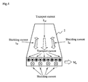
- FIG. 4 is a second diagram showing shielding currents and a magnetization direction of a tape wire in a superconducting magnet according to the present embodiment
- FIG. 5 is a second perspective diagram of windings in the superconducting magnet according to the present embodiment
- FIG. 1 is a first perspective diagram of windings in a superconducting magnet according to the present embodiment
- FIG. 2 is a first diagram showing shielding currents and a magnetization direction of a tape wire in the superconducting magnet according to the present embodiment
- FIG. 3 is a first cross-sectional diagram of the windings in the superconducting magnet according
- FIG. 6 is a second cross-sectional diagram of the windings in the superconducting magnet according to the present embodiment
- FIG. 7 is a diagram showing magnetic field distribution of an outer AC winding and an inner AC winding in the superconducting magnet according to the present embodiment.
- a superconducting magnet 1 includes: a superconducting winding 2 composed of a superconductor; an outer AC winding 4 composed of a superconductor or a non-superconductor wound coaxially with the central axis 3 of the superconducting winding 2, at an outer side of the superconducting winding 2; a DC power source unit 5 configured to supply a DC current to the superconducting winding 2; and an AC power source unit 6 configured to supply an AC current to the outer AC winding 4.
- the superconducting winding 2 may be any winding as long as it is composed of a superconductor, and particularly a winding composed of a high temperature superconducting wire such as a Bi2223 Ag-sheathed tape wire, Y-based or a rare earth-based thin film conductor is used herein.
- a superconducting layer When forming a superconducting magnet using these wires, typically a superconducting layer has a tape-like shape with several millimeters in width (e.g., Bi-2223 wire: approx. 4 mm; Y-123 wire: approx. 10 mm), and with several to several hundred micrometers in thickness (e.g., Bi-2223 wire: approx. 200 ⁇ m; Y-123 wire: approx. 1 ⁇ m); and when such a wire is wound and supplied with a current I DC (that denotes a transport current), uniformity of the central magnetic field is diminished due to magnetization caused by a shielding current in the winding itself
- FIG. 2 shows the magnetization caused by the shielding current at the time.
- a transport current I DC flows from one end toward the other end of a tape wire, and shielding currents I M flow in the tape wider-width surface of the superconducting winding 2.
- the magnetization (that is denoted with Mv) is caused in a direction perpendicular to the tape surface by the shielding current I M , whereby uniformity of the central magnetic field in the superconducting magnet 1 is diminished.
- the transport current I DC which flows from one end toward the other end of the tape wire and the shielding current I M which is a closed loop current cannot be discriminated from each other.
- FIG. 3 is an arrow view taken along the arrow A in FIG. 1 .
- a tape-shaped superconducting winding 2 is wound a plurality of turns, and an outer AC winding 4 is wound at the outer side thereof.
- a central magnetic field B I indicated with the arrow a is produced by the transport current I DC in the superconducting winding 2. It is noted that although the superconducting winding 2 is shown as only a single layer in FIG. 3 , the superconducting winding 2 may be wound around so as to form a plurality of layers.
- An AC magnetic field B AC indicated with the arrow b in FIG. 3 is applied by the outer AC winding 4 in a direction perpendicular to the magnetization Mv shown in FIG. 17 and FIG. 2 . That is, the AC magnetic field B AC is applied by supplying an AC current I AC to the outer AC winding 4.
- the magnetization Mv in a direction perpendicular to the tape surface is eliminated by the abnormal transverse-field effects, and is changed into a magnetization M P in a direction parallel to the tape surface.
- FIG. 4 shows magnetization caused by the shielding current after the change.
- the shielding currents I M become to flow as a pair at the upper surface and the lower surface of the tape wire by the abnormal transverse-field effects, and the magnetization Mv is eliminated and changed into the magnetization M P , which is parallel to the tape surface.
- the magnetization M P which is parallel to the tape surface, has no influence on uniformity of the central magnetic field in the superconducting magnet 1.
- the central magnetic field B I in the superconducting magnet 1 produced by the transport current I DC can be maintained uniformly.
- the outer AC winding 4 may be a winding composed of a superconductor or may be a winding composed of a non-superconductor. That is, either type of winding is available as long as a certain magnitude of AC magnetic field (lower limit value), which is determined according to the thickness, the critical current density, and the transport current I DC of the superconducting winding 2, can be applied.
- a certain magnitude of AC magnetic field lower limit value
- ⁇ 0 is a space permeability
- Jc is a critical current density
- I C is a critical current
- I DC is a transport current
- d is a tape thickness of the superconducting winding 2. That is, a threshold Bth of the AC magnetic field to be applied is determined according to the critical current density J C , the tape thickness d, and the transport current I DC (or a load factor I DC /I C expressed by the transport current to the critical current). Therefore, the invention of the present application can be achieved by designing the outer AC winding 4 so that such a Bth can be applied. And, as described above, since a tape of a high temperature superconducting wire is very thin as around several millimeters in width, and around several to several hundred micrometers in thickness, the value of the AC magnetic field to be applied can be micrified.
- the AC current is not required to be constantly supplied to the outer AC winding 4, that is, the magnetization Mv in a direction perpendicular to the tape surface can be changed into the magnetization M P in a direction parallel to the tape surface by supplying a defined current as the transport current I DC only for a predetermined time period (e.g., several to several ten seconds or several to several thousand cycles), whereby the state can be maintained and the central magnetic field B I in the superconducting magnet 1 can be maintained uniformly.
- a predetermined time period e.g., several to several ten seconds or several to several thousand cycles
- a value of the current may be gradually decreased.
- influence of the magnetization M P can be minimized by gradually attenuating the AC current.
- the central magnetic field in the superconducting magnet 1 can be uniformized by applying the AC magnetic field to the superconducting winding 2.
- inductance of the outer AC winding 4 becomes large, there a large power source may be required.
- it may be arranged to further provide an inner AC winding 7 at the inner side of the superconducting winding 2 in order to negate the magnetic field of the outer AC winding 4.
- FIG. 5 is a perspective diagram of the superconducting magnet 1 in the case where the inner AC winding 7 is provided therein; and FIG. 6 is an arrow view taken along the arrow B in FIG. 5 .
- the superconducting magnet 1 is provided with the inner AC winding 7 at an inner side of the superconducting winding 2 wherein the inner AC winding 7 is connected to an AC power source unit 6; and directions of a current flowing in the outer AC winding 4 and a current flowing in the inner AC winding 7 are controlled to be opposite to each other.
- the magnetic field (see FIG. 7 (B) ) produced at the inner side of the inner AC winding 7 can be counterbalanced (see FIG. 7 (C) ), therefore the inductance can be diminished.
- the current can be supplied by a small power source.
- the inner AC winding 7 may be a winding composed of a superconductor or may be a winding composed of a non-superconductor.
- the process and time for winding them can be reduced and therefore efficiency of the manufacturing process can be greatly enhanced.
- the magnetic field of the outer AC winding 4 produced inside the inner AC winding 7 can be negated by the magnetic field of the inner AC winding 7, thereby allowing to diminish the inductance, and thus it can be operated by a small power source.
- FIG. 8 is a perspective diagram of windings in a superconducting magnet according to the present embodiment
- FIG. 9 is a cross-sectional diagram of the windings in the superconducting magnet according to the present embodiment.
- a superconducting magnet 1 includes: a superconducting winding 2 composed of a superconductor; an AC winding 8 composed of a superconductor or a non-superconductor that is wound encircling the superconducting winding 2 in a direction perpendicular to the winding direction of the superconducting winding 2; a DC power source unit 5 configured to supply a DC current to the superconducting winding 2; and an AC power source unit 6 configured to supply an AC current to the AC winding 8.
- FIG. 9 is an arrow view taken along the arrow C in FIG. 8 .
- the AC winding 8 is wound in a direction perpendicular to a winding direction of the superconducting winding 2 (in the same direction with the axis of the superconducting winding 2) so as to enclose the superconducting winding 2, and then to connect to the AC power source unit 6, as shown in FIG. 8 and FIG. 9 .
- the magnetization M P is that indicated with the arrow of the magnetization M P shown in FIG. 4 is rotated by 90 degrees while maintaining it in parallel to the tape surface, and the magnetization M P has no influence on uniformity of the central magnetic field.
- the central magnetic field B I produced by the transport current can be maintained uniformly.
- the AC winding 8 may be a winding composed of a superconductor or may be a winding composed of a non-superconductor. That is, either type of winding is available as long as a certain magnitude of AC magnetic field (lower limit value), which is determined according to the thickness, the critical current density, and the transport current I DC of the superconducting winding 2, can be applied.
- a certain magnitude of AC magnetic field lower limit value
- the AC current is not required to be constantly supplied to the outer AC winding 8, that is, the magnetization Mv in a direction perpendicular to the tape surface can be changed into the magnetization M P in a direction parallel to the tape surface by supplying a defined current as the transport current I DC only for a predetermined time period (e.g., several to several ten seconds or several to several thousand cycles), whereby the state can be maintained and the central magnetic field B I can be maintained uniformly.
- a predetermined time period e.g., several to several ten seconds or several to several thousand cycles
- the central magnetic field in the superconducting magnet can be uniformized by applying the AC magnetic field to the superconducting winding 2.
- the superconducting magnet 1 Since the superconducting magnet 1 according to each of the above-described embodiments is capable of maintaining high uniformity of the central magnetic field, it is suitable for use in NMR (Nuclear Magnetic Resonance) and MRI (Magnetic Resonance Imaging) which require highly accurate uniformity of the central magnetic field.
- NMR Nuclear Magnetic Resonance
- MRI Magnetic Resonance Imaging
- the magnetization Mv is changed into M P by performing the process of applying the AC magnetic field to the superconducting winding 2 for a predetermined time period in advance of measurement. And then, measurement of an object is performed while application of the AC magnetic field is in a stopped state. Unless the current value is changed, other objects can be measured in sequence as it is.
- the magnetization Mv is changed into M P by applying the AC magnetic field for a predetermined time period, again.
- the superconducting magnet 1 by applying the AC magnetic field, a current distribution of the superconducting winding 2 changes, and the quantized magnetic flux lines move thereby generating heat. Then by the generated heat, the temperature of the superconducting winding 2 slightly rises for a very short time period, and the critical current density slightly decreases. And then, the superconducting winding is cooled again immediately after the critical current density decreased, whereby the critical current density increases, and thus the influence of the quantized magnetic flux lines on the thermal fluctuation can be suppressed. As a result, the magnetic flux creep, a phenomenon that the quantized magnetic flux lines are moved by the thermal fluctuation, can be significantly suppressed, and there is an additional advantage that uniformity of the central magnetic field can be maintained for a long time.
- the temperature of the refrigerant is raised (e.g., around 1°C to 2 °C) by externally applying a pressure to the superconducting magnet 1, whereby the magnetic flux creep, which is a phenomenon that the quantized magnetic flux lines are moved by the thermal fluctuation, can be significantly suppressed due to the rise in temperature of the refrigerant functioning similarly to that described above, and uniformity of the central magnetic field can be maintained for a long time.
- the superconducting magnet according to the present invention may be configured like FIGS. 10 (A) and (B) .
- the AC magnetic field may be individually applied to each of a plurality of sites constituting the superconducting winding 2.
- FIG. 10 (A) the AC magnetic field is applied individually to each layer, including a layer as a set of the outer AC winding 4 and the inner AC winding 7, of the superconducting winding 2 composed of three layers.
- the inductance can be further diminished and the power source can be reduced in size.
- FIG. 10 (B) the AC magnetic field is applied individually to each layer of the superconducting winding 2 composed of three layers including the AC winding 8 which is wound with respect to each layer.
- the power source may be reduced in volume by forming a resonant circuit in which a capacitor and a resistance are connected with the AC winding in series.
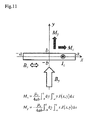
- FIG. 11 shows a numerical analysis model
- Table 1 shows calculation parameters.
- FIG. 12 shows results of the simulation. As shown in FIG. 12 , it is recognized that the magnetization M y exponentially decreases, and the current in the tape-shaped superconducting wire is uniformized. That is, it is indicated that the magnetization M y in a direction perpendicular to the tape surface is eliminated.
- FIG. 13 shows a cross-sectional diagram viewed from one side of the section in the center of the superconducting magnet test-produced for the experiment; the following Table 2 shows specifications of a superconducting coil; and Table 3 shows specifications of a copper coil.
- the superconducting magnet for the experiment is configured with a superconducting coil composed of GdBa 2 Cu 3 O x superconductor, and coils composed of copper wires respectively wound coaxially with the superconducting coil at an inner side and an outer side of the superconducting coil.
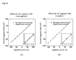
- FIG. 14 and FIG. 15 show results of the experiments.
- FIG. 14 shows each magnitude of the central magnetic field with respect to each current value in a demagnetization process and a magnetization process; and
- FIG. 15 shows each deviation from the straight line in FIG. 14.
- FIG. 14 (A) and FIG. 15 (A) are results when the AC magnetic field was not applied; and
- FIG. 14 (B) and FIG. 15 (B) are results when the AC magnetic field was applied.
- hysteresis disappears and the results become into a straight-like line by applying the AC magnetic field.
- the deviation from the straight line when the AC magnetic field is applied in FIG. 14 becomes around 0.1% or less, and it is recognized that the deviation is improved close to the measurement limit.
Landscapes
- Physics & Mathematics (AREA)
- Engineering & Computer Science (AREA)
- Power Engineering (AREA)
- Condensed Matter Physics & Semiconductors (AREA)
- General Physics & Mathematics (AREA)
- Electromagnetism (AREA)
- Magnetic Resonance Imaging Apparatus (AREA)
Abstract
Description
- The present invention relates to a superconducting magnet in which the central magnetic field is uniformized.
- For example, generally NbTi multifilamentary wires are utilized as windings of superconducting magnets to be used for nuclear magnetic resonance apparatuses and the like (see
FIG. 16 ). The NbTi multifilamentary wire is small in magnetization of a winding since the diameter of one filament is so small as several to several ten micrometers. Liquid helium (with an atmospheric pressure boiling point of around 4 K) is used as a refrigerant for the NbTi multifilamentary wire. The liquid helium is expensive due to lack in resources, and there is a risk of exhaustion sooner or later. - Therefore, research and development for a nuclear magnetic resonance apparatus and the like utilizing a superconductor that is capable of possessing a superconducting property even with the use of a material abundant in resources such as liquid hydrogen (with an atmospheric pressure boiling point of around 20 K) and liquid nitrogen (with an atmospheric pressure boiling point of around 77 K) is in progress. A superconducting wire using these types of superconductors typically has a shape of a tape as shown in
FIG. 17 , and a superconducting layer thereof is around several millimeters in width, and around several to several hundred micrometers in thickness. Thus, when such a superconducting wire is used for a winding, magnetization of the winding becomes very large, and an electric current flowing in the winding becomes non-uniform due to a shielding current, whereby uniformity of the central magnetic field becomes diminished. - On the other hand,
non-patent literatures 1 to 4 disclose dissertations regarding abnormal transverse-field effects, that is, when an AC magnetic field perpendicular to a DC transverse magnetic field is applied thereto, magnetization M in the direction of the DC magnetic field asymptotically varies with the periodic variation of the AC magnetic field; and when an amplitude of the AC magnetic field becomes larger than a certain value, the magnetization M is eliminated in a steady state. Further,non-patent literatures -
- NPTL 1: Kazuo Funaki and Kaoru Yamafuji, "Abnormal Transverse-Field Effects in Nonideal Type II Superconductors I. A Linear Array of Monofilamentary Wires", Japanese Journal of Applied Physics, Vol. 21, No. 2, Feb. 1982, pp. 299-304
- NPTL 2: Kazuo Funaki, Teruhide Niidome and Kaoru Yamafuji, "Abnormal Transverse-Field Effects in
- NPTL 3: Kazuo Funaki, Minoru Noda and Kaoru Yamafuji, "Abnormal Transverse-Field Effects in
- NPTL 4: Kazuo Funaki, Teruhide Niidome and Kaoru Yamafuji, "Abnormal Transverse-Field Effects in Current Carrying Superconducting Wires", Technology Reports of Kyushu University, Vol. 56, No. 1, Jan. 1983, pp. 45-51 NPTL 5: Ernst Helmut Brandt and Grigorii P.Mikitik, "Why an ac Magnetic Field Shifts the Irreversibility Line in Type-II Superconductors", Physical Review Letters, Vol. 89, No. 2, July 2002, 027002
- NPTL 6: Ernst Helmut Brandt and Grigorii P.Mikitik, "Shaking of the critical state by a small transverse ac field can cause rapid relaxation in superconductors", Superconductor Science and Technology, Vol. 17, No. 2, Feb. 2004, pp. S1-S5
- However, the techniques disclosed in the above-described
non-patent literatures 1 to 6 are to demonstrate that the abnormal transverse-field effects are exerted on a single wire or a one-dimensional array of a plurality of short-length sample wires, and those are not techniques to ensure uniformity of the central magnetic field in a superconducting magnet wound with a superconducting wire. - The present invention provides a superconducting magnet and the like in which magnetization caused by a shielding current of a superconducting winding is eliminated whereby the current to be supplied to the superconducting winding is uniformized, and thus uniformity of the central magnetic field is secured.
- A superconducting magnet disclosed in the present application includes a superconducting winding composed of a superconductor, and a magnetic field application unit configured to apply an AC magnetic field in a direction perpendicular to a direction of magnetization caused by a shielding current in the superconducting winding.
- As is described above, in the superconducting magnet disclosed in the present application, an effect is exerted as follows: since it applies an AC magnetic field in a direction perpendicular to a direction of magnetization caused by a shielding current in the superconducting winding composed of a superconductor; the magnetization caused by the shielding current can be eliminated, and thus the central magnetic field can be uniformized.
- In the superconducting magnet disclosed in the present application, the magnetic field application unit applies the AC magnetic field, and has an AC winding to which an AC current is supplied so that current flow directions at an outer side of the superconducting winding and at an inner side thereof are opposite to each other.
- As is described above, in the superconducting magnet disclosed in the present application, an effect is exerted as follows: since it has an AC winding to which an AC current is supplied so that current flow directions at an outer side of the superconducting winding and at an inner side thereof are opposite to each other; the magnetic field of the outer AC winding produced inside the inner AC winding can be negated by the magnetic field of the inner AC winding, thereby allowing to diminish the inductance, and thus it can be operated by a small power source.
- In the superconducting magnet disclosed in the present application, the magnetic field application unit has an outer AC winding composed of a superconductor or non-superconductor wound coaxially with the superconducting winding, at an outer side of the superconducting winding, and an AC current is supplied to the outer AC winding.
- As is described above, in the superconducting magnet disclosed in the present application, an effect is exerted as follows: since it has an outer AC winding composed of a superconductor or non-superconductor wound coaxially with the superconducting winding, at an outer side of the superconducting winding, and an AC current is supplied to the outer AC winding; it can apply an AC magnetic field in a direction perpendicular to a direction of magnetization caused by a shielding current in the superconducting winding, whereby the magnetization caused by the shielding current is eliminated, and thus the central magnetic field can be uniformized.
- In the superconducting magnet disclosed in the present application, the magnetic field application unit has an inner AC winding composed of a superconductor or non-superconductor wound coaxially with the superconducting winding, at an inner side of the superconducting winding, and a current direction to be supplied to the outer AC winding, and a direction of a current to be supplied to the inner AC winding are to be in opposite directions to each other.
- As is described above, in the superconducting magnet disclosed in the present application, an effect is exerted as follows: since it has an inner AC winding composed of a superconductor or non-superconductor wound coaxially with the superconducting winding, at an inner side of the superconducting winding, and a direction of a current to be supplied to the outer AC winding and a direction of a current to be supplied to the inner AC winding are to be in opposite directions to each other; the magnetic field of the outer AC winding produced inside the inner AC winding can be negated by the magnetic field of the inner AC winding, thereby allowing to diminish the inductance, and thus it can be operated by a small power source.
- In the superconducting magnet disclosed in the present application, the magnetic field application unit has an AC winding composed of a superconductor or non-superconductor wound encircling the superconducting winding in a direction perpendicular to a winding direction of the superconducting winding, and an AC current is supplied to the AC winding.
- As is described above, in the superconducting magnet disclosed in the present application, an effect is exerted as follows: since it has an AC winding composed of a superconductor or non-superconductor wound encircling the superconducting winding in a direction perpendicular to a winding direction of the superconducting winding, and an AC current is supplied to the AC winding; it can apply an AC magnetic field in a direction perpendicular to a direction of magnetization caused by a shielding current in the superconducting winding, whereby the magnetization caused by the shielding current is eliminated, and thus the central magnetic field can be uniformized. Also, since it can be configured so that the current flow directions at an outer side of the superconducting winding and at an inner side thereof are opposite to each other, the magnetic field of the outer AC winding produced inside the inner AC winding can be negated by the magnetic field of the inner AC winding, thereby allowing to diminish the inductance, and thus it can be operated by a small power source.
- The superconducting magnet disclosed in the present application, the superconducting winding is a tape-shaped winding composed of a high temperature superconductor.
- As is described above, in the superconducting magnet disclosed in the present application, an effect is exerted as follows: since it is a tape-shaped winding composed of a high temperature superconductor; liquid helium which is expensive and lack in resources is not required to be used, so instead thereof, a material which is inexpensive and abundant in resources can be effectively utilized.
- In the superconducting magnet disclosed in the present application, the magnetic field application unit gradually attenuates an AC magnetic field to be applied
- As is described above, in the superconducting magnet disclosed in the present application, an effect is exerted as follows: since the magnetic field application unit gradually attenuates an AC magnetic field to be applied; magnetization in a direction of the AC magnetic field by the abnormal transverse-field effects can be diminished, and thus influence of the superconducting magnet on the central magnetic field can be minimized.
- The superconducting magnet disclosed in the present application, further includes a temperature control unit configured to raise a temperature of the superconducting winding for a predetermined time period.
- As is described above, in the superconducting magnet disclosed in the present application, an effect is exerted as follows: since it includes a temperature control unit configured to raise a temperature of the superconducting winding for a predetermined time period; the temperature of the superconducting winding is raised for a predetermined time period whereby the critical current density slightly decreases, and the temperature of the superconducting winding is cooled again immediately after the critical current density decreased whereby the critical current density increases, and thus influence of the quantized magnetic flux lines on the thermal fluctuation can be suppressed. As a result, the magnetic flux creep, a phenomenon that the quantized magnetic flux lines are moved by the thermal fluctuation, can be significantly suppressed, and thus uniformity of the central magnetic field can be maintained for a long time.
- In the superconducting magnet disclosed in the present application, the temperature control unit is the AC winding, and the AC winding and the superconducting winding are arranged to be in a closely contact state.
- As is described above, in the superconducting magnet disclosed in the present application, an effect is exerted as follows: since the AC winding and the superconducting winding are arranged to be in a closely contact state; a heat generated in the AC winding is transferred to the superconducting winding and then the temperature of the superconducting winding is raised for a predetermined time period whereby the critical current density slightly decreases, and the temperature of the superconducting winding is cooled again immediately after the critical current density decreased whereby the critical current density increases, and thus influence of the quantized magnetic flux lines on the thermal fluctuation can be suppressed. As a result, the magnetic flux creep, a phenomenon that the quantized magnetic flux lines are moved by the thermal fluctuation, can be significantly suppressed, and uniformity of the central magnetic field can be maintained for a long time.
- In the superconducting magnet disclosed in the present application, the temperature control unit has a pressure control section configured to control a pressure in a housing where the superconducting magnet is accommodated with a refrigerant.
- As is described above, in the superconducting magnet disclosed in the present application, an effect is exerted as follows: since the temperature control unit controls a pressure in a housing where the superconducting magnet is accommodated with a refrigerant; the temperature of the refrigerant in the housing is raised and then the temperature of the superconducting winding is raised for a predetermined time period whereby the critical current density slightly decreases, and the temperature of the superconducting winding is cooled again immediately after the critical current density decreased whereby the critical current density increases, and thus influence of the quantized magnetic flux lines on the thermal fluctuation can be suppressed. As a result, the magnetic flux creep, a phenomenon that the quantized magnetic flux lines are moved by the thermal fluctuation, can be significantly suppressed, and uniformity of the central magnetic field can be maintained for a long time.
- A nuclear magnetic resonance apparatus disclosed in the present application is that the superconducting magnet is used therefor, in which the magnetic field application unit applies an AC magnetic field for a predetermined time period in advance of measuring an object to be measured, and does not apply the AC magnetic field at the time of measurement.
- As is described above, in the nuclear magnetic resonance apparatus disclosed in the present application, an effect is exerted as follows: since it applies an AC magnetic field for a predetermined time period in advance of measuring an object to be measured, and does not apply the AC magnetic field at the time of measurement; there is no influence of the AC magnetic field during the measurement, and therefore precise measurement can be achieved.
- In the nuclear magnetic resonance apparatus disclosed in the present application, the magnetic field application unit applies the AC magnetic field when a value of a current to be supplied to the superconducting winding is changed.
- As is described above, in the nuclear magnetic resonance apparatus disclosed in the present application, an effect is exerted as follows: since it applies the AC magnetic field when a value of a current to be supplied to the superconducting winding is changed; even when the measurement environment is changed and the current value is changed, the central magnetic field in the superconducting magnet can be uniformized by eliminating magnetization caused by the shielding current, and thus precise measurement can be achieved. That is, even though the superconducting magnet is reset and the shielding current flows again when the current value is changed, magnetization caused by the shielding current can be eliminated by applying the AC magnetic field.
-
-
FIG. 1 is a first perspective diagram of windings in a superconducting magnet according to the first embodiment. -
FIG. 2 is a first diagram showing shielding currents and a magnetization direction of a tape wire in the superconducting magnet according to the first embodiment. -
FIG. 3 is a first cross-sectional diagram of the windings in the superconducting magnet according to the first embodiment. -
FIG. 4 is a second diagram showing shielding currents and a magnetization direction of a tape wire in a superconducting magnet according to the first embodiment. -
FIG. 5 is a second perspective diagram of windings in the superconducting magnet according to the first embodiment. -
FIG. 6 is a second cross-sectional diagram of the windings in the superconducting magnet according to the first embodiment. -
FIG. 7 is a diagram showing magnetic field distribution of an outer AC winding and an inner AC winding in the superconducting magnet according to the first embodiment. -
FIG. 8 is a perspective diagram of windings in a superconducting magnet according to a second embodiment. -
FIG. 9 is a cross-sectional diagram of the windings in the superconducting magnet according to the second embodiment. -
FIG. 10 shows cross-sectional diagrams of windings in superconducting magnets according to another embodiment. -
FIG. 11 shows a simulation model of a superconducting magnet according to an example of the present invention. -
FIG. 12 shows results of the simulation of the superconducting magnet according to the example of the present invention. -
FIG. 13 shows a configuration of experimental coils of a superconducting magnet according to an example of the present invention. -
FIG. 14 shows first charts indicating results of an experiment of the superconducting magnet according to an example of the present invention. -
FIG. 15 shows second charts indicating results of an experiment of the superconducting magnet according to an example of the present invention. -
FIG. 16 is a diagram showing a superconducting magnet where a conventional multifilamentary wire is used therefor. -
FIG. 17 is a diagram showing a superconducting magnet where a conventional tape wire is used therefor. - Hereinafter, embodiments of the present invention will be described. Throughout the present embodiments, identical components are denoted with the same numerals respectively.
- A superconducting magnet according to the present embodiment will be described with the use of
FIG. 1 to FIG. 7 .FIG. 1 is a first perspective diagram of windings in a superconducting magnet according to the present embodiment;FIG. 2 is a first diagram showing shielding currents and a magnetization direction of a tape wire in the superconducting magnet according to the present embodiment;FIG. 3 is a first cross-sectional diagram of the windings in the superconducting magnet according to the present embodiment;FIG. 4 is a second diagram showing shielding currents and a magnetization direction of a tape wire in a superconducting magnet according to the present embodiment;FIG. 5 is a second perspective diagram of windings in the superconducting magnet according to the present embodiment;FIG. 6 is a second cross-sectional diagram of the windings in the superconducting magnet according to the present embodiment; andFIG. 7 is a diagram showing magnetic field distribution of an outer AC winding and an inner AC winding in the superconducting magnet according to the present embodiment. - A
superconducting magnet 1 according to the present embodiment includes: a superconducting winding 2 composed of a superconductor; an outer AC winding 4 composed of a superconductor or a non-superconductor wound coaxially with thecentral axis 3 of the superconducting winding 2, at an outer side of the superconducting winding 2; a DCpower source unit 5 configured to supply a DC current to the superconducting winding 2; and an ACpower source unit 6 configured to supply an AC current to the outer AC winding 4. - The superconducting winding 2 may be any winding as long as it is composed of a superconductor, and particularly a winding composed of a high temperature superconducting wire such as a Bi2223 Ag-sheathed tape wire, Y-based or a rare earth-based thin film conductor is used herein. When forming a superconducting magnet using these wires, typically a superconducting layer has a tape-like shape with several millimeters in width (e.g., Bi-2223 wire: approx. 4 mm; Y-123 wire: approx. 10 mm), and with several to several hundred micrometers in thickness (e.g., Bi-2223 wire: approx. 200 µm; Y-123 wire: approx. 1 µm); and when such a wire is wound and supplied with a current IDC (that denotes a transport current), uniformity of the central magnetic field is diminished due to magnetization caused by a shielding current in the winding itself.
-
FIG. 2 shows the magnetization caused by the shielding current at the time. As shown inFIG. 2 , a transport current IDC flows from one end toward the other end of a tape wire, and shielding currents IM flow in the tape wider-width surface of the superconducting winding 2. The magnetization (that is denoted with Mv) is caused in a direction perpendicular to the tape surface by the shielding current IM, whereby uniformity of the central magnetic field in thesuperconducting magnet 1 is diminished. However, in this case, the transport current IDC which flows from one end toward the other end of the tape wire and the shielding current IM which is a closed loop current cannot be discriminated from each other. - According to the present embodiment, in order to eliminate the magnetization in a direction perpendicular to the tape surface as shown in
FIG. 17 andFIG. 2 , an AC magnetic field is applied, as shown inFIG. 3 , in a direction perpendicular to the direction of the magnetization caused by the shielding current in the superconducting winding 2.FIG. 3 is an arrow view taken along the arrow A inFIG. 1 . As shown inFIG. 3 , a tape-shaped superconducting winding 2 is wound a plurality of turns, and an outer AC winding 4 is wound at the outer side thereof. A central magnetic field BI indicated with the arrow a is produced by the transport current IDC in the superconducting winding 2. It is noted that although the superconducting winding 2 is shown as only a single layer inFIG. 3 , the superconducting winding 2 may be wound around so as to form a plurality of layers. - An AC magnetic field BAC indicated with the arrow b in
FIG. 3 is applied by the outer AC winding 4 in a direction perpendicular to the magnetization Mv shown inFIG. 17 andFIG. 2 . That is, the AC magnetic field BAC is applied by supplying an AC current IAC to the outer AC winding 4. By applying the AC magnetic field BAC to the superconducting winding 2, the magnetization Mv in a direction perpendicular to the tape surface is eliminated by the abnormal transverse-field effects, and is changed into a magnetization MP in a direction parallel to the tape surface. -
FIG. 4 shows magnetization caused by the shielding current after the change. As shown inFIG. 4 , the shielding currents IM become to flow as a pair at the upper surface and the lower surface of the tape wire by the abnormal transverse-field effects, and the magnetization Mv is eliminated and changed into the magnetization MP, which is parallel to the tape surface. The magnetization MP, which is parallel to the tape surface, has no influence on uniformity of the central magnetic field in thesuperconducting magnet 1. In other words, the central magnetic field BI in thesuperconducting magnet 1 produced by the transport current IDC can be maintained uniformly. - In this regard, the outer AC winding 4 may be a winding composed of a superconductor or may be a winding composed of a non-superconductor. That is, either type of winding is available as long as a certain magnitude of AC magnetic field (lower limit value), which is determined according to the thickness, the critical current density, and the transport current IDC of the superconducting winding 2, can be applied.
- Hereinafter, the magnitude of the AC magnetic field will be described more specifically. The following equation is established on the threshold (lower limit value) [T] of the abnormal transverse-field effects.

- Where µ0 is a space permeability, Jc is a critical current density, IC is a critical current, IDC is a transport current, and d is a tape thickness of the superconducting winding 2. That is, a threshold Bth of the AC magnetic field to be applied is determined according to the critical current density JC, the tape thickness d, and the transport current IDC (or a load factor IDC/IC expressed by the transport current to the critical current). Therefore, the invention of the present application can be achieved by designing the outer AC winding 4 so that such a Bth can be applied. And, as described above, since a tape of a high temperature superconducting wire is very thin as around several millimeters in width, and around several to several hundred micrometers in thickness, the value of the AC magnetic field to be applied can be micrified.
- Further, the AC current is not required to be constantly supplied to the outer AC winding 4, that is, the magnetization Mv in a direction perpendicular to the tape surface can be changed into the magnetization MP in a direction parallel to the tape surface by supplying a defined current as the transport current IDC only for a predetermined time period (e.g., several to several ten seconds or several to several thousand cycles), whereby the state can be maintained and the central magnetic field BI in the
superconducting magnet 1 can be maintained uniformly. When the superconducting magnet according to the present embodiment is used for measurement etc., the magnetization Mv may be eliminated in advance of the measurement. - Furthermore, when supplying the AC current, a value of the current may be gradually decreased. In other words, since the magnetization MP after application of the AC magnetic field is maintained in the state when application of the AC magnetic field was stopped, influence of the magnetization MP can be minimized by gradually attenuating the AC current.
- Thus as described above, the central magnetic field in the
superconducting magnet 1 can be uniformized by applying the AC magnetic field to the superconducting winding 2. However, in this case, since inductance of the outer AC winding 4 becomes large, there a large power source may be required. Then, in the present embodiment, it may be arranged to further provide an inner AC winding 7 at the inner side of the superconducting winding 2 in order to negate the magnetic field of the outer AC winding 4. -
FIG. 5 is a perspective diagram of thesuperconducting magnet 1 in the case where the inner AC winding 7 is provided therein; andFIG. 6 is an arrow view taken along the arrow B inFIG. 5 . As shown inFIG. 5 andFIG. 6 , thesuperconducting magnet 1 is provided with the inner AC winding 7 at an inner side of the superconducting winding 2 wherein the inner AC winding 7 is connected to an ACpower source unit 6; and directions of a current flowing in the outer AC winding 4 and a current flowing in the inner AC winding 7 are controlled to be opposite to each other. In short, as shown inFIG. 7 , among the magnetic fields (seeFIG. 7 (A) ) produced at the inner side of the outer AC winding 4, the magnetic field (seeFIG. 7 (B) ) produced at the inner side of the inner AC winding 7 can be counterbalanced (seeFIG. 7 (C) ), therefore the inductance can be diminished. Thus, the current can be supplied by a small power source. - In this regard, similarly to the outer AC winding 4, the inner AC winding 7 may be a winding composed of a superconductor or may be a winding composed of a non-superconductor. Moreover, by forming the respective AC windings into a tape-like shape similarly to the superconducting winding 2, the process and time for winding them can be reduced and therefore efficiency of the manufacturing process can be greatly enhanced.
- Thus as described above, the magnetic field of the outer AC winding 4 produced inside the inner AC winding 7 can be negated by the magnetic field of the inner AC winding 7, thereby allowing to diminish the inductance, and thus it can be operated by a small power source.
- A superconducting magnet according to the present embodiment will be described with the use of
FIG. 8 andFIG. 9 .FIG. 8 is a perspective diagram of windings in a superconducting magnet according to the present embodiment; andFIG. 9 is a cross-sectional diagram of the windings in the superconducting magnet according to the present embodiment. - It is noted that, in the present embodiment, overlapped descriptions with those of the first embodiment will be omitted.
- A
superconducting magnet 1 according to the present embodiment includes: a superconducting winding 2 composed of a superconductor; an AC winding 8 composed of a superconductor or a non-superconductor that is wound encircling the superconducting winding 2 in a direction perpendicular to the winding direction of the superconducting winding 2; a DCpower source unit 5 configured to supply a DC current to the superconducting winding 2; and an ACpower source unit 6 configured to supply an AC current to the AC winding 8. -
FIG. 9 is an arrow view taken along the arrow C inFIG. 8 . According to the present embodiment, in order to eliminate the magnetization Mv in a direction perpendicular to the tape surface as shown inFIG. 17 andFIG. 2 , the AC winding 8 is wound in a direction perpendicular to a winding direction of the superconducting winding 2 (in the same direction with the axis of the superconducting winding 2) so as to enclose the superconducting winding 2, and then to connect to the ACpower source unit 6, as shown inFIG. 8 andFIG. 9 . The AC magnetic field BAC indicated with the arrow c (the arrow being in a direction perpendicular to the plane of paper) inFIG. 9 is applied by supplying the AC current IAC to the AC winding 8; and the magnetization Mv in a direction perpendicular to the tape surface is eliminated by the abnormal transverse-field effects, and thus is changed into the magnetization MP in a direction parallel to the tape surface. The magnetization MP is that indicated with the arrow of the magnetization MP shown inFIG. 4 is rotated by 90 degrees while maintaining it in parallel to the tape surface, and the magnetization MP has no influence on uniformity of the central magnetic field. Thus, similarly to the case of the first embodiment, the central magnetic field BI produced by the transport current can be maintained uniformly. - In this regard, here also the AC winding 8 may be a winding composed of a superconductor or may be a winding composed of a non-superconductor. That is, either type of winding is available as long as a certain magnitude of AC magnetic field (lower limit value), which is determined according to the thickness, the critical current density, and the transport current IDC of the superconducting winding 2, can be applied.
- Further, the AC current is not required to be constantly supplied to the outer AC winding 8, that is, the magnetization Mv in a direction perpendicular to the tape surface can be changed into the magnetization MP in a direction parallel to the tape surface by supplying a defined current as the transport current IDC only for a predetermined time period (e.g., several to several ten seconds or several to several thousand cycles), whereby the state can be maintained and the central magnetic field BI can be maintained uniformly.
- Thus as described above, the central magnetic field in the superconducting magnet can be uniformized by applying the AC magnetic field to the superconducting winding 2.
- Since the
superconducting magnet 1 according to each of the above-described embodiments is capable of maintaining high uniformity of the central magnetic field, it is suitable for use in NMR (Nuclear Magnetic Resonance) and MRI (Magnetic Resonance Imaging) which require highly accurate uniformity of the central magnetic field. - When the superconducting magnet according to the present invention is used in NMR or MRI, the magnetization Mv is changed into MP by performing the process of applying the AC magnetic field to the superconducting winding 2 for a predetermined time period in advance of measurement. And then, measurement of an object is performed while application of the AC magnetic field is in a stopped state. Unless the current value is changed, other objects can be measured in sequence as it is. When the measurement environment is changed, and the current value is changed or the apparatus is reset therein, the magnetization Mv is changed into MP by applying the AC magnetic field for a predetermined time period, again.
- Further, in the
superconducting magnet 1 according to the present invention, by applying the AC magnetic field, a current distribution of the superconducting winding 2 changes, and the quantized magnetic flux lines move thereby generating heat. Then by the generated heat, the temperature of the superconducting winding 2 slightly rises for a very short time period, and the critical current density slightly decreases. And then, the superconducting winding is cooled again immediately after the critical current density decreased, whereby the critical current density increases, and thus the influence of the quantized magnetic flux lines on the thermal fluctuation can be suppressed. As a result, the magnetic flux creep, a phenomenon that the quantized magnetic flux lines are moved by the thermal fluctuation, can be significantly suppressed, and there is an additional advantage that uniformity of the central magnetic field can be maintained for a long time. - Furthermore, a heat generated in the AC winding is transferred to the superconducting winding 2, whereby the magnetic flux creep, which is a phenomenon that the quantized magnetic flux lines are moved by the thermal fluctuation, can be significantly suppressed due to a similar function to that described above, and uniformity of the central magnetic field can be maintained for a long time.
- Still further, the temperature of the refrigerant is raised (e.g., around 1°C to 2 °C) by externally applying a pressure to the
superconducting magnet 1, whereby the magnetic flux creep, which is a phenomenon that the quantized magnetic flux lines are moved by the thermal fluctuation, can be significantly suppressed due to the rise in temperature of the refrigerant functioning similarly to that described above, and uniformity of the central magnetic field can be maintained for a long time. - The superconducting magnet according to the present invention may be configured like
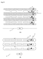
FIGS. 10 (A) and (B) . In short, the AC magnetic field may be individually applied to each of a plurality of sites constituting the superconducting winding 2. As an example, inFIG. 10 (A) , the AC magnetic field is applied individually to each layer, including a layer as a set of the outer AC winding 4 and the inner AC winding 7, of the superconducting winding 2 composed of three layers. Thus, by the above arrangement, the inductance can be further diminished and the power source can be reduced in size. And, as another example, inFIG. 10 (B) , the AC magnetic field is applied individually to each layer of the superconducting winding 2 composed of three layers including the AC winding 8 which is wound with respect to each layer. - Additionally, in each of the above-described embodiments, the power source may be reduced in volume by forming a resonant circuit in which a capacitor and a resistance are connected with the AC winding in series. Examples
- The following simulation was conducted on a superconducting magnet according to the present invention.
FIG. 11 shows a numerical analysis model, and Table 1 shows calculation parameters. With the use of the numerical analysis model inFIG. 11 , when a transport current Iz is supplied to a tape-shaped superconducting wire whereby an external DC magnetic field By and an AC magnetic field Bx are applied thereto, temporal variations of respective magnetizations Mx and My are calculated.[Table 1] Tape width 2a 10 mm Tape thickness 2b 0.1 mm Critical current density Jc 200 A/mm2 Critical current Ic 200 A Supply current Iz 100 A DC magnetic field By 1 T AC magnetic field amplitude Bxm 0.1 T Frequency 1 Hz -
FIG. 12 shows results of the simulation. As shown inFIG. 12 , it is recognized that the magnetization My exponentially decreases, and the current in the tape-shaped superconducting wire is uniformized. That is, it is indicated that the magnetization My in a direction perpendicular to the tape surface is eliminated. - The following experiments were conducted on a superconducting magnet according to the present invention.
FIG. 13 shows a cross-sectional diagram viewed from one side of the section in the center of the superconducting magnet test-produced for the experiment; the following Table 2 shows specifications of a superconducting coil; and Table 3 shows specifications of a copper coil. The superconducting magnet for the experiment is configured with a superconducting coil composed of GdBa2Cu3Ox superconductor, and coils composed of copper wires respectively wound coaxially with the superconducting coil at an inner side and an outer side of the superconducting coil.[Table 2] Superconductor GdBa2Cu3Ox Tape width 5 mm Superconducting layer thickness 1.5 µm Critical current 224 A (77 K) Inner diameter 63.0 mm Outer diameter 72.1 mm Average height 89.5 mm Number of turns 70.5 turns [Table 3] Wire diameter 1 mm Inner diameter (inside/ outside) 53.0/79.0 mm Outer diameter (inside/outside) 57.0/82.9 mm Height 139.8 mm Number of turns 264 turns Current amplitude 30 A Frequency 100 Hz Supply time 30 s -
FIG. 14 andFIG. 15 show results of the experiments.FIG. 14 shows each magnitude of the central magnetic field with respect to each current value in a demagnetization process and a magnetization process; andFIG. 15 shows each deviation from the straight line inFIG. 14. FIG. 14 (A) andFIG. 15 (A) are results when the AC magnetic field was not applied; andFIG. 14 (B) andFIG. 15 (B) are results when the AC magnetic field was applied. As is obvious fromFIG. 14 , hysteresis disappears and the results become into a straight-like line by applying the AC magnetic field. Also, as is obvious fromFIG. 15 , the deviation from the straight line when the AC magnetic field is applied inFIG. 14 becomes around 0.1% or less, and it is recognized that the deviation is improved close to the measurement limit. - The above experimental results show, in the superconducting magnet according to the present invention, magnetization in a direction perpendicular to the tape surface of the superconducting tape can be eliminated, and thus the central magnetic field can be maintained uniformly.
-
- 1.
- Superconducting magnet
- 2.
- Superconducting winding
- 3.
- Central axis
- 4.
- Outer AC winding
- 5.
- DC power source unit
- 6.
- AC power source unit
- 7.
- Inner AC winding
- 8.
- AC winding
Claims (12)
- A superconducting magnet, comprising:a superconducting winding composed of a superconductor; and a magnetic field application unit configured to apply an AC magnetic field in a direction perpendicular to a direction of magnetization caused by a shielding current in the superconducting winding.
- The superconducting magnet according to claim 1, wherein
the magnetic field application unit applies the AC magnetic field; and has an AC winding to which an AC current is supplied so that current flow directions at an outer side of the superconducting winding and at an inner side thereof are opposite to each other. - The superconducting magnet according to claim 1 or 2, wherein
the magnetic field application unit has an outer AC winding composed of a superconductor or non-superconductor wound coaxially with the superconducting winding, at an outer side of the superconducting winding; and an AC current is supplied to the outer AC winding. - The superconducting magnet according to claim 2 or 3, wherein
the magnetic field application unit has an inner AC winding composed of a superconductor or non-superconductor wound coaxially with the superconducting winding, at an inner side of the superconducting winding; and a direction of a current to be supplied to the outer AC winding and a direction of a current to be supplied to the inner AC winding are to be in opposite directions to each other. - The superconducting magnet according to claim 1 or 2, wherein
the magnetic field application unit has an AC winding composed of a superconductor or non-superconductor wound encircling the superconducting winding in a direction perpendicular to a winding direction of the superconducting winding; and an AC current is supplied to the AC winding. - The superconducting magnet according to any one of claims 1 to 5, wherein
the superconducting winding is a tape-shaped winding composed of a high temperature superconductor. - The superconducting magnet according to any one of claims 1 to 6, wherein
the magnetic field application unit gradually attenuates an AC magnetic field to be applied. - The superconducting magnet according to any one of claims 1 to 7, further comprising:a temperature control unit configured to raise a temperature of the superconducting winding for a predetermined time period.
- The superconducting magnet according to claim 8, wherein,
the temperature control unit is the AC winding; and the AC winding and the superconducting winding are arranged to be in a closely contact state. - The superconducting magnet according to claim 8 or 9, wherein
the temperature control unit has a pressure control section configured to control a pressure in a housing where the superconducting magnet is accommodated with a refrigerant. - A nuclear magnetic resonance apparatus using the superconducting magnet according to any one of claims 1 to 10, wherein
the magnetic field application unit applies an AC magnetic field for a predetermined time period in advance of measuring an object to be measured; and does not apply the AC magnetic field at the time of measurement. - The nuclear magnetic resonance apparatus according to claim 11, wherein
the magnetic field application unit applies the AC magnetic field when a value of a current to be supplied to the superconducting winding is changed.
Applications Claiming Priority (2)
| Application Number | Priority Date | Filing Date | Title |
|---|---|---|---|
| JP2011111708 | 2011-05-18 | ||
| PCT/JP2012/062777 WO2012157745A1 (en) | 2011-05-18 | 2012-05-18 | Superconducting magnet and nuclear magnetic resonance device |
Publications (2)
| Publication Number | Publication Date |
|---|---|
| EP2711940A1 true EP2711940A1 (en) | 2014-03-26 |
| EP2711940A4 EP2711940A4 (en) | 2015-04-08 |
Family
ID=47177059
Family Applications (1)
| Application Number | Title | Priority Date | Filing Date |
|---|---|---|---|
| EP12786075.7A Withdrawn EP2711940A4 (en) | 2011-05-18 | 2012-05-18 | SUPERCONDUCTING MAGNET AND NUCLEAR MAGNETIC RESONANCE DEVICE |
Country Status (5)
| Country | Link |
|---|---|
| US (1) | US9406422B2 (en) |
| EP (1) | EP2711940A4 (en) |
| JP (1) | JP6029109B2 (en) |
| KR (1) | KR101884444B1 (en) |
| WO (1) | WO2012157745A1 (en) |
Families Citing this family (6)
| Publication number | Priority date | Publication date | Assignee | Title |
|---|---|---|---|---|
| JP6590573B2 (en) * | 2015-07-29 | 2019-10-16 | 住友電気工業株式会社 | Operation method of superconducting magnet device |
| WO2017029676A1 (en) * | 2015-08-19 | 2017-02-23 | KAFRI, Amizur | Hybrid superconducting magnetic device |
| CN106783492A (en) * | 2016-12-14 | 2017-05-31 | 聚束科技(北京)有限公司 | A kind of magnetic lens and excitation current control method |
| JP6926728B2 (en) * | 2017-06-29 | 2021-08-25 | 住友電気工業株式会社 | Superconducting magnets, superconducting magnet operation methods and inspection equipment |
| KR102715071B1 (en) * | 2019-03-06 | 2024-10-08 | 토카막 에너지 리미티드 | Transport current saturated HTS magnet |
| JP2025178947A (en) * | 2024-05-27 | 2025-12-09 | 国立研究開発法人理化学研究所 | Superconducting magnet device |
Family Cites Families (6)
| Publication number | Priority date | Publication date | Assignee | Title |
|---|---|---|---|---|
| JPS574541A (en) * | 1980-06-12 | 1982-01-11 | Toshiba Corp | Nuclear magnetic resonance apparatus |
| JP3670708B2 (en) * | 1995-04-10 | 2005-07-13 | 新日本製鐵株式会社 | Magnetization method of cylindrical superconducting magnet |
| US5986453A (en) * | 1997-11-07 | 1999-11-16 | Varian, Inc. | AC magnetic susceptibility control of superconducting materials in nuclear magnetic resonance (NMR) probes |
| CN100359776C (en) * | 2005-02-04 | 2008-01-02 | 北京云电英纳超导电缆有限公司 | Superconducting Fault Current Limiter with Shorting Ring |
| JP4699293B2 (en) * | 2006-06-15 | 2011-06-08 | 三菱電機株式会社 | Superconducting magnet |
| US8253416B2 (en) * | 2009-03-10 | 2012-08-28 | Time Medical Holdings Company Limited | Superconductor magnetic resonance imaging system and method (super-MRI) |
-
2012
- 2012-05-18 EP EP12786075.7A patent/EP2711940A4/en not_active Withdrawn
- 2012-05-18 KR KR1020137027312A patent/KR101884444B1/en not_active Expired - Fee Related
- 2012-05-18 WO PCT/JP2012/062777 patent/WO2012157745A1/en not_active Ceased
- 2012-05-18 JP JP2013515219A patent/JP6029109B2/en not_active Expired - Fee Related
-
2013
- 2013-11-15 US US14/081,612 patent/US9406422B2/en not_active Expired - Fee Related
Also Published As
| Publication number | Publication date |
|---|---|
| US9406422B2 (en) | 2016-08-02 |
| JP6029109B2 (en) | 2016-11-24 |
| US20140296074A1 (en) | 2014-10-02 |
| NZ617975A (en) | 2015-12-24 |
| WO2012157745A1 (en) | 2012-11-22 |
| JPWO2012157745A1 (en) | 2014-07-31 |
| KR20140052983A (en) | 2014-05-07 |
| EP2711940A4 (en) | 2015-04-08 |
| KR101884444B1 (en) | 2018-08-01 |
Similar Documents
| Publication | Publication Date | Title |
|---|---|---|
| US9406422B2 (en) | Superconducting magnet and nuclear magnetic resonance device | |
| Tosaka et al. | R&D project on HTS magnets for ultrahigh-field MRI systems | |
| Kajikawa et al. | Designs and tests of shaking coils to reduce screening currents induced in HTS insert coils for NMR magnet | |
| Ainslie | Transport AC loss in high temperature superconducting coils | |
| Kajikawa et al. | A simple method to eliminate shielding currents for magnetization perpendicular to superconducting tapes wound into coils | |
| Hu et al. | Trapped field of a Bitter-like HTS magnet using partial multi-pulse magnetization | |
| Jiang et al. | Transport AC loss measurements in single-and two-layer parallel coated conductor arrays with low turn numbers | |
| Kajikawa et al. | Reduction of screening-current-induced fields in an HTS tape winding using toroidal arrangement of shaking coil | |
| Kvitkovic et al. | Influence of interlayer separation on magnetic shielding properties of 2G HTS sheets made of 46 mm wide RABiTS tape | |
| Yoon et al. | Field mapping of the jointless HTS solenoid magnet in a persistent current mode operation | |
| Tsuda et al. | Suitable excitation condition in overshooting process for suppressing magnetic field attenuation in Y-based coated conductor coils | |
| Liu et al. | Study of a low-frequency wireless charging system crossing the metal Dewar wall of a high-temperature superconducting magnet | |
| Miyazaki et al. | Development of a 5.1 T conduction-cooled YBCO coil composed of a stack of 12 single pancakes | |
| Miyazaki et al. | Evaluation of magnetic field homogeneity of a conduction-cooled REBCO magnet with a room-temperature bore of 200 mm | |
| Nguyen et al. | Temperature dependence of total AC loss in high-temperature superconducting tapes | |
| Yuan et al. | Characterization of magnetic field in the bitter-like HTS magnet magnetized by multiple excitation methods | |
| Muto et al. | Evaluation and analysis of a 10 T-class small coil using REBCO coated conductors laminated with thick copper tapes | |
| Ballarino et al. | Transformer-based measurement of critical currents in superconducting cables: Tutorial 51 | |
| Nishijima et al. | Development of Liquid Nitrogen Cooled RE–Ba–Cu–O (RE= Rare Earth) Superconducting Magnet for NMR Use | |
| Yoon et al. | Design and fabrication of double pancake coil using 2G wire for conduction cooled superconducting magnet | |
| Nguyen et al. | High-temperature superconducting undulators for future X-ray free electron laser systems | |
| Kumar et al. | Electromagnetic analysis of 1MJ class of high temperature superconducting magnetic energy storage (SMES) coil to be used in power applications | |
| Miyagi et al. | Study on thermal measurement method of AC loss in a Conduction-Cooled HTS coil | |
| Obana et al. | Investigation of long time constants of magnetic fields generated by the JT-60SA CS1 module | |
| Koyanagi et al. | Fabrication of YBCO small test coils for accelerator magnet development |
Legal Events
| Date | Code | Title | Description |
|---|---|---|---|
| PUAI | Public reference made under article 153(3) epc to a published international application that has entered the european phase |
Free format text: ORIGINAL CODE: 0009012 |
|
| 17P | Request for examination filed |
Effective date: 20131128 |
|
| AK | Designated contracting states |
Kind code of ref document: A1 Designated state(s): AL AT BE BG CH CY CZ DE DK EE ES FI FR GB GR HR HU IE IS IT LI LT LU LV MC MK MT NL NO PL PT RO RS SE SI SK SM TR |
|
| DAX | Request for extension of the european patent (deleted) | ||
| RIC1 | Information provided on ipc code assigned before grant |
Ipc: G01R 33/3815 20060101ALI20150226BHEP Ipc: H01F 6/06 20060101AFI20150226BHEP Ipc: G01R 33/421 20060101ALN20150226BHEP Ipc: H01F 5/00 20060101ALI20150226BHEP Ipc: G01R 33/3875 20060101ALI20150226BHEP |
|
| RA4 | Supplementary search report drawn up and despatched (corrected) |
Effective date: 20150309 |
|
| STAA | Information on the status of an ep patent application or granted ep patent |
Free format text: STATUS: THE APPLICATION HAS BEEN WITHDRAWN |
|
| 18W | Application withdrawn |
Effective date: 20190524 |