EP2711624A1 - Mounting device for lighting sources - Google Patents
Mounting device for lighting sources Download PDFInfo
- Publication number
- EP2711624A1 EP2711624A1 EP13182188.6A EP13182188A EP2711624A1 EP 2711624 A1 EP2711624 A1 EP 2711624A1 EP 13182188 A EP13182188 A EP 13182188A EP 2711624 A1 EP2711624 A1 EP 2711624A1
- Authority
- EP
- European Patent Office
- Prior art keywords
- carrier body
- wall
- hole
- carrier
- axis
- Prior art date
- Legal status (The legal status is an assumption and is not a legal conclusion. Google has not performed a legal analysis and makes no representation as to the accuracy of the status listed.)
- Granted
Links
- 230000000284 resting effect Effects 0.000 claims abstract 2
- 230000015572 biosynthetic process Effects 0.000 claims description 4
- 230000008878 coupling Effects 0.000 claims description 4
- 238000010168 coupling process Methods 0.000 claims description 4
- 238000005859 coupling reaction Methods 0.000 claims description 4
- 239000004020 conductor Substances 0.000 claims 3
- 238000005755 formation reaction Methods 0.000 claims 1
- 239000000463 material Substances 0.000 description 5
- 230000005855 radiation Effects 0.000 description 4
- 239000007769 metal material Substances 0.000 description 2
- 238000000034 method Methods 0.000 description 2
- 235000001674 Agaricus brunnescens Nutrition 0.000 description 1
- 229910052782 aluminium Inorganic materials 0.000 description 1
- XAGFODPZIPBFFR-UHFFFAOYSA-N aluminium Chemical compound [Al] XAGFODPZIPBFFR-UHFFFAOYSA-N 0.000 description 1
- 230000000295 complement effect Effects 0.000 description 1
- 238000009434 installation Methods 0.000 description 1
Images

Classifications
-
- F—MECHANICAL ENGINEERING; LIGHTING; HEATING; WEAPONS; BLASTING
- F21—LIGHTING
- F21V—FUNCTIONAL FEATURES OR DETAILS OF LIGHTING DEVICES OR SYSTEMS THEREOF; STRUCTURAL COMBINATIONS OF LIGHTING DEVICES WITH OTHER ARTICLES, NOT OTHERWISE PROVIDED FOR
- F21V21/00—Supporting, suspending, or attaching arrangements for lighting devices; Hand grips
- F21V21/14—Adjustable mountings
- F21V21/26—Pivoted arms
-
- F—MECHANICAL ENGINEERING; LIGHTING; HEATING; WEAPONS; BLASTING
- F21—LIGHTING
- F21V—FUNCTIONAL FEATURES OR DETAILS OF LIGHTING DEVICES OR SYSTEMS THEREOF; STRUCTURAL COMBINATIONS OF LIGHTING DEVICES WITH OTHER ARTICLES, NOT OTHERWISE PROVIDED FOR
- F21V21/00—Supporting, suspending, or attaching arrangements for lighting devices; Hand grips
- F21V21/14—Adjustable mountings
- F21V21/30—Pivoted housings or frames
Definitions
- the description relates to devices for mounting lighting sources.
- Various embodiments can relate to the mounting of solid-state lighting sources, for example of the LED type.
- Known devices for mounting lighting sources can provide for the use of joints of various types (for example to allow the orientation of the lighting source).
- Various embodiments make it possible to control the orientation of the lighting source by applying, for example by hand, a calibrated torque, with the possible capability, on the part of the mounting device, to maintain the control position assigned thereto.
- an embodiment in the context of this description indicates that a particular configuration, structure or feature described in relation to the embodiment is included in at least one embodiment. Therefore, phrases such as "in one embodiment", which may occur at various points in this description, do not necessarily refer to the same embodiment. Moreover, particular forms, structures or features may be combined in any suitable manner in one or more embodiments.
- reference sign 10 denotes as a whole a device for mounting lighting sources.
- the exemplary embodiment considered here relates to a mounting device 10 which makes it possible to mount, on a supporting surface such as a ceiling or a false ceiling S, a light lighting source L formed, for example, by a spotlight.
- a lighting source L which can use, as a light radiation source LS, a solid-state light radiation source, for example an LED source.
- the lighting source L and in particular the light radiation source LS can be intended to be coupled to the device in accordance with various embodiments only with a view to installation.
- the device 10 is intended to allow the orientation of the lighting source L (and therefore the orientation of the light radiation beam emitted by the source LS) with respect to:
- the second axis X2 may not be orthogonal thereto and may be, for example, oriented in a bent or oblique direction with respect to the axis X1.
- the following may be identifiable within the scope of the mounting device 10:
- the carrier arm 14 can extend downwards starting from the carrier body 12, in such a manner that the lighting source L is as it were suspended on the carrier body 12.
- the carrier body 12 can have different structures and shapes.
- a carrier body 12 including two profiled bodies 12a, 12b (for example made of a metallic material or a pressed plastic material) which have a channel-like structure and are coupled to one another, with the channel-like structures being arranged so as to mutually face one another and so as to be mutually orthogonal in relation to one another so as to jointly define a box-like carrier body 12 having a parallelepiped shape.
- the body 12a is that intended to be fixed to the mounting surface (for example the ceiling or false ceiling S) and the body 12b is that which carries the carrier arm 14.
- the two bodies 12a and 12b can be coupled to one another, for example, by means of a snap coupling, or by means of screws or other known fixing devices.
- the body 12b can include an extruded profile, for example of aluminum, light metal material, plastic.
- the carrier body 12 can have structures and shapes which differ entirely from those presented here by way of example.
- the carrier body 12 for example the portion 12b, can have a wall (at the bottom, in the mounting condition presented here by way of example) denoted by 120, in which a hole 16 having an axis is made.
- this axis can coincide with the first axis of orientation of the lighting source L which has already been introduced, with reference to figure 1 .
- the axis of the hole 16 is in actual fact denoted by the reference sign X1.
- the hole 16 can be a circular hole.
- the carrier arm 14, which can be inserted in the hole 16 may include:
- the distal end 14c can be configured, for example by means of the presence of one or more pins or shafts 14d, in such a way as to produce, in the coupled state with the lighting source L, a joint or articulation capable of allowing the orientation of the lighting source L about an articulation axis which can coincide with the axis X2 already introduced beforehand, with reference to figure 1 .
- the axis of the pin or of the pins 14d is also denoted by the reference sign X2 in figure 3 .
- the carrier arm 14 can be inserted in the hole 16 in such a way that the enlarged head portion 14a can rest on the periphery of the hole 16 provided in the wall 120 of the carrier body 12 internally with respect to the carrier body 12.
- the enlarged head portion 14a of the carrier arm 14 can rest on the periphery of the hole 16 with the interposition of an annular gasket 18.
- the gasket 18 can be elastic and/or can be assimilated with an O-ring.
- the stem part or portion 14b of said arm 14 can protrude outwardly of the carrier body 12 and therefore support, at the distal end 14c thereof, the lighting source L.
- the reference sign 20 denotes a retaining cap which can be fixed to the carrier body 12 internally thereof in such a way as to act on the carrier arm 14 to urge the enlarged head portion 14a to rest on the periphery of the hole 16 (possibly with the interposition of the gasket 18).
- the cap 20 can include a washer portion 20a (in one piece or separate) facing the enlarged head portion 14a of the carrier arm 14 and rotatably cooperating therewith, for example in as much as the washer portion 20a is fitted onto an end tang 14e of the carrier arm 14 which protrudes beyond the enlarged head portion 14a.
- a washer portion 20a in one piece or separate facing the enlarged head portion 14a of the carrier arm 14 and rotatably cooperating therewith, for example in as much as the washer portion 20a is fitted onto an end tang 14e of the carrier arm 14 which protrudes beyond the enlarged head portion 14a.
- the carrier arm 14 (and the lighting source L carried thereby at the distal end 14c thereof) can be made to rotate about the axis X1 of the hole 16, thus making it possible to implement a rotational movement (for example through 360° or more) in the horizontal plane, as shown by the double-headed arrow AA' in figure 1 .
- the mounting device shown can have a passageway for electrical wires directed towards the lighting source L.
- this passageway can involve:
- the enlarged head portion 14a of the carrier arm 14 and the cap 20 can have mutually facing surfaces comprising at least one sculptured surface with the function of braking the rotational movement of the carrier arm 14 about the axis X of the hole 16.
- this solution can be achieved in that the enlarged head portion 14a of the carrier arm 14 has, facing towards the cap 20 (thus towards the washer 20a), a row of radial ribs 140 intended to perform the aforementioned braking action, acting frictionally against a protruding portion of the cap 20 and/or against the circular ring surface of the washer portion 20a which faces towards the enlarged head portion 14a.
- the aforementioned braking action (the intensity of which can also be determined by the degree of elasticity of the gasket 18) can have the function of ensuring that the carrier arm 14 (and the lighting source L carried thereby) maintain their position with respect to the axis X1, towards which these elements have been moved, for example, by a simple manual rotational action exerted on the lighting source L.
- various embodiments can provide for the presence, laterally with respect to the hole 16, of ribs 22 (which can be easily formed in the body 12b when the latter is in the form of an extruded profile) intended to cooperate in a hook-like link with the cap 20.
- the cap 20 can have a general channel-like shape with lateral extensions 20c having a distal hook-like formation 20d (see for example figure 4 ).
- the formation 20d can hook onto the ribs 22 (which for this purpose can have enlarged head portions) so as to allow coupling of the cap 20 to the carrier body 12 in a general snap-type coupling configuration.
- the presence of the pins 14d exemplified here constitutes one of various possibilities which can be used to make it possible to implement the vertical pivoting movement of the light source L according to the double-headed arrow BB' in figure 1 .
- the aforementioned form of articulation about the articulation axis X2 can be implemented with a configuration which is complementary with respect to that exemplified here: in particular, instead of providing one or more pins 14d which are carried by the distal end 14c of the arm 14 and are intended to engage in one or more corresponding openings (not shown in the drawings) provided in the light source L, it is possible to consider providing the pin or pins in question on the light source and the opening or openings at the distal end 14c of the arm 14.
Landscapes
- Engineering & Computer Science (AREA)
- General Engineering & Computer Science (AREA)
- Non-Portable Lighting Devices Or Systems Thereof (AREA)
- Arrangement Of Elements, Cooling, Sealing, Or The Like Of Lighting Devices (AREA)
Abstract
Description
- The description relates to devices for mounting lighting sources.
- Various embodiments can relate to the mounting of solid-state lighting sources, for example of the LED type.
- Known devices for mounting lighting sources can provide for the use of joints of various types (for example to allow the orientation of the lighting source).
- To use these devices, it may be necessary to have tools and/or fixing elements, sometimes having to resort to additional external elements of various kinds.
- In the context of application indicated above, there is a need for solutions which make it possible to satisfy one or more of the following requirements:
- the possibility to rotate the light source, in particular through an angle of 360° and beyond, by simply applying, for example by hand, a torque,
- the possibility to connect a joint mounting element or arm (made of a plastic material or of any other material) to a carrier body, for example in the form of an extruded profile, without having to have specific tools or fixing devices,
- avoiding a situation where the weight of the lighting source has to be supported by elements such as caps or nuts, and/or
- allowing the passage of electrical wires through the mounting device.
- It is an object of various embodiments to satisfy the requirement outlined above.
- Various embodiments achieve this object owing to a mounting device having the features indicated specifically in the claims which follow.
- The claims form an integral part of the technical teaching provided here in relation to the invention.
- Various embodiments can provide for one or more of the following features:
- the presence of a washer element and/or of an elastic gasket element between a carrier body, for example an extruded carrier body, and an articulated carrier arm for the lighting source,
- the presence of a carrier arm which can be connected to a carrier body, for example an extruded carrier body, in a simple manner, for example by means of a cap adjoining the head portion of the carrier arm,
- configuring the carrier arm in a manner substantially identical to a mushroom or hammer shape, i.e. with an enlarged head portion, and
- the possibility to produce at least the carrier arm in the form of a hollow tubular structure which allows for the passage of electrical wires.
- Various embodiments make it possible to obtain low production costs, easy mounting and reliable use.
- Various embodiments make it possible to control the orientation of the lighting source by applying, for example by hand, a calibrated torque, with the possible capability, on the part of the mounting device, to maintain the control position assigned thereto.
- Various embodiments make it possible to produce structures which are on the whole thin and have dimensions so as to allow the passage, in their interior, of electrical wires even of a large cross section.
- Various embodiments will now be described, purely by way of non-limiting example, with reference to the accompanying figures, in which:
-
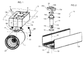
figure 1 is a general perspective view of a mounting device for lighting sources supporting in mounted form one such source, -
figure 2 is an exploded perspective view of a device according to embodiments, -
figure 3 is a perspective view showing the device shown infigure 2 in a mounted state, and -
figure 4 reproduces, on an enlarged scale, the portion infigure 3 indicated by IV. - In the following description, various specific details aimed at providing a fuller understanding of various exemplary embodiments are explained. The embodiments may be implemented without one or more of the specific details or using other methods, components, materials, etc. In other cases, known structures, materials or operations are not shown or described in detail so that the various aspects of the embodiments may be understood more clearly.
- The reference to "an embodiment" in the context of this description indicates that a particular configuration, structure or feature described in relation to the embodiment is included in at least one embodiment. Therefore, phrases such as "in one embodiment", which may occur at various points in this description, do not necessarily refer to the same embodiment. Moreover, particular forms, structures or features may be combined in any suitable manner in one or more embodiments.
- The reference signs used here are provided solely for the sake of convenience and therefore do not define the scope of protection or ambit of the embodiments.
- In the figures,
reference sign 10 denotes as a whole a device for mounting lighting sources. - The exemplary embodiment considered here relates to a
mounting device 10 which makes it possible to mount, on a supporting surface such as a ceiling or a false ceiling S, a light lighting source L formed, for example, by a spotlight. This may be, for example, a lighting source L which can use, as a light radiation source LS, a solid-state light radiation source, for example an LED source. - Even though they are shown here for illustrative clarity and ease of understanding, the lighting source L and in particular the light radiation source LS can be intended to be coupled to the device in accordance with various embodiments only with a view to installation.
- In various embodiments, as exemplified here, the
device 10 is intended to allow the orientation of the lighting source L (and therefore the orientation of the light radiation beam emitted by the source LS) with respect to: - a first axis X1, which, in the mounting position shown here by way of example (with reference to mounting on a ceiling or false ceiling S extending in a substantially horizontal plane), can be oriented in a substantially vertical direction, and
- a second axis X2, which extends in a generically transverse direction with respect to the first axis X1 and therefore, in the example considered here, can be oriented in a substantially horizontal direction.
- In various embodiments, even though it is transverse with respect to the first axis X1, the second axis X2 may not be orthogonal thereto and may be, for example, oriented in a bent or oblique direction with respect to the axis X1.
- In various embodiments, the following may be identifiable within the scope of the mounting device 10:
- a
carrier body 12, which can be fixed to the supporting surface, such as the ceiling or false ceiling S, for example by means of anupper wall 12a provided with holes H (according to the current methods of use for mounting the lighting rails), and - a
carrier arm 14, which protrudes from thecarrier body 12 with the capability to extend in a connecting manner between thecarrier body 12 and the lighting source L. - In the solution presented here by way of example, with the
carrier body 12 mounted in a ceiling, thecarrier arm 14 can extend downwards starting from thecarrier body 12, in such a manner that the lighting source L is as it were suspended on thecarrier body 12. - According to the embodiments, the
carrier body 12 can have different structures and shapes. - The examples presented in the figures relate to a
carrier body 12 including two profiledbodies like carrier body 12 having a parallelepiped shape. In the exemplary embodiments under consideration here, thebody 12a is that intended to be fixed to the mounting surface (for example the ceiling or false ceiling S) and thebody 12b is that which carries thecarrier arm 14. - In various embodiments, the two
bodies - In various embodiments, the
body 12b can include an extruded profile, for example of aluminum, light metal material, plastic. - In various embodiments, the
carrier body 12 can have structures and shapes which differ entirely from those presented here by way of example. - In the exemplary embodiments under consideration here, the
carrier body 12, for example theportion 12b, can have a wall (at the bottom, in the mounting condition presented here by way of example) denoted by 120, in which ahole 16 having an axis is made. - In various embodiments, this axis can coincide with the first axis of orientation of the lighting source L which has already been introduced, with reference to
figure 1 . For this reason, infigures 2 ,3 and 4 , the axis of thehole 16 is in actual fact denoted by the reference sign X1. - In various embodiments, the
hole 16 can be a circular hole. - In various embodiments, the
carrier arm 14, which can be inserted in thehole 16, may include: - an enlarged
head portion 14a, and - a
stem portion 14b having adistal end 14c (opposite to the enlargedhead portion 14a). - In various embodiments, the
distal end 14c can be configured, for example by means of the presence of one or more pins orshafts 14d, in such a way as to produce, in the coupled state with the lighting source L, a joint or articulation capable of allowing the orientation of the lighting source L about an articulation axis which can coincide with the axis X2 already introduced beforehand, with reference tofigure 1 . - For this reason, the axis of the pin or of the
pins 14d is also denoted by the reference sign X2 infigure 3 . - As can be seen more clearly by comparing the views of
figure 2 (exploded perspective view) and offigure 3 (assembled perspective view), in various embodiments thecarrier arm 14 can be inserted in thehole 16 in such a way that the enlargedhead portion 14a can rest on the periphery of thehole 16 provided in thewall 120 of thecarrier body 12 internally with respect to thecarrier body 12. - In various embodiments, the
enlarged head portion 14a of thecarrier arm 14 can rest on the periphery of thehole 16 with the interposition of anannular gasket 18. - In various embodiments, the
gasket 18 can be elastic and/or can be assimilated with an O-ring. - In various embodiments, with the
carrier arm 14 inserted in thehole 16, the stem part orportion 14b of saidarm 14 can protrude outwardly of thecarrier body 12 and therefore support, at thedistal end 14c thereof, the lighting source L. - The
reference sign 20 denotes a retaining cap which can be fixed to thecarrier body 12 internally thereof in such a way as to act on thecarrier arm 14 to urge theenlarged head portion 14a to rest on the periphery of the hole 16 (possibly with the interposition of the gasket 18). - For this purpose, the
cap 20 can include awasher portion 20a (in one piece or separate) facing theenlarged head portion 14a of thecarrier arm 14 and rotatably cooperating therewith, for example in as much as thewasher portion 20a is fitted onto anend tang 14e of thecarrier arm 14 which protrudes beyond theenlarged head portion 14a. - The carrier arm 14 (and the lighting source L carried thereby at the
distal end 14c thereof) can be made to rotate about the axis X1 of thehole 16, thus making it possible to implement a rotational movement (for example through 360° or more) in the horizontal plane, as shown by the double-headed arrow AA' infigure 1 . - In various embodiments, the mounting device shown can have a passageway for electrical wires directed towards the lighting source L.
- In various embodiments, this passageway can involve:
- the fact that the
carrier arm 14 has a tubular structure and thus has a longitudinal (axial) cavity for the passage of these electrical wires, and/or - the fact that the
cap 20 has an overall annular structure with acentral opening 20b for the passage of electrical wires, which can then extend through the longitudinal cavity of thecarrier arm 14. - In various embodiments, as can be seen more clearly in the enlarged view of
figure 4 , theenlarged head portion 14a of thecarrier arm 14 and the cap 20 (for example thewasher portion 20a thereof) can have mutually facing surfaces comprising at least one sculptured surface with the function of braking the rotational movement of thecarrier arm 14 about the axis X of thehole 16. - In the exemplary embodiment shown in
figure 4 , this solution can be achieved in that theenlarged head portion 14a of thecarrier arm 14 has, facing towards the cap 20 (thus towards thewasher 20a), a row ofradial ribs 140 intended to perform the aforementioned braking action, acting frictionally against a protruding portion of thecap 20 and/or against the circular ring surface of thewasher portion 20a which faces towards theenlarged head portion 14a. - In various embodiments, the aforementioned braking action (the intensity of which can also be determined by the degree of elasticity of the gasket 18) can have the function of ensuring that the carrier arm 14 (and the lighting source L carried thereby) maintain their position with respect to the axis X1, towards which these elements have been moved, for example, by a simple manual rotational action exerted on the lighting source L.
- For fixing the
cap 20 to thecarrier body 12, for example on the inner side of thewall 120, various embodiments can provide for the presence, laterally with respect to thehole 16, of ribs 22 (which can be easily formed in thebody 12b when the latter is in the form of an extruded profile) intended to cooperate in a hook-like link with thecap 20. - In various embodiments, the
cap 20 can have a general channel-like shape withlateral extensions 20c having a distal hook-like formation 20d (see for examplefigure 4 ). The formation 20d can hook onto the ribs 22 (which for this purpose can have enlarged head portions) so as to allow coupling of thecap 20 to thecarrier body 12 in a general snap-type coupling configuration. - As regards the formation of the articulation or joint at the
distal end 14c of thecarrier arm 14, the presence of thepins 14d exemplified here of course constitutes one of various possibilities which can be used to make it possible to implement the vertical pivoting movement of the light source L according to the double-headed arrow BB' infigure 1 . - In various embodiments, the aforementioned form of articulation about the articulation axis X2 can be implemented with a configuration which is complementary with respect to that exemplified here: in particular, instead of providing one or
more pins 14d which are carried by thedistal end 14c of thearm 14 and are intended to engage in one or more corresponding openings (not shown in the drawings) provided in the light source L, it is possible to consider providing the pin or pins in question on the light source and the opening or openings at thedistal end 14c of thearm 14. - Without affecting the principle of the invention, the constructional details and embodiments may therefore vary, also significantly, with respect to that illustrated here purely by way of non-limiting example, without thereby departing from the scope of protection: this scope of protection is defined by the accompanying claims.
Claims (10)
- A device for mounting a lighting source (L) on a carrier body (12), the device including:- a wall (120) in the carrier body (12), the wall (120) having a hole (16), the hole having an axis (X1),- a carrier arm (14) having an enlarged head portion (14a) and a stem portion (14b), the carrier arm (14) inserted in the hole (16) in the wall (120) of the carrier body (12) with the enlarged head portion (14a) resting on the periphery of the hole (16) in the wall (120) of the carrier body (12) internally of the carrier body (12) and the stem portion (14b) protruding outwardly of the carrier body (12);- a retaining cap (20) fixed internally of the carrier body (12) and urging the enlarged head portion (14a) of the carrier arm (14) towards the periphery of the hole (16) in the wall (120) of the carrier body (12) permitting rotation of the carrier arm (14) about the axis (X1) of the hole (16) in the wall (120) of the carrier body (12), and- an articulation joint (14d) for mounting the lighting source (L) at the distal end (14c) of the carrier arm (14), the articulation joint (14d) having an articulation axis (X2) transverse to the axis (X1) of the hole (16) in the wall (120) of the carrier body (12).
- The device as claimed in claim 1, wherein the retaining cap (20) includes a washer portion (20a) facing the enlarged head portion (14a) of the carrier arm (14) and rotatably cooperating therewith.
- The device as claimed in claim 1 or claim 2, wherein the enlarged head portion (14a) of the carrier arm (14) rests against the periphery of the hole (16) in the wall (120) of the carrier body (12) with the interposition of an annular, preferably elastic, gasket (18).
- The device as claimed in any of the preceding claims, wherein the hole (16) in the wall (120) of the carrier body (12) is a circular hole.
- The device as claimed in any of the preceding claims, including a passageway for electrical conductors, the passageway involving at least one of:- the carrier arm (14) being tubular and having a longitudinal passage cavity for electrical conductors, and/or- the retaining cap (20) being annular with a central passage opening (20b) for electrical conductors.
- The device as claimed in any of the preceding claims, wherein the enlarged head portion (14a) of the carrier arm (14) and the retaining cap (20) have at least one sculptured surface (140) to brake the rotation of the carrier arm (14) about the axis (X1) of the hole (16) in the wall (120) of the carrier body (12).
- The device as claimed in any of the preceding claims, wherein the wall (120) of the carrier body (12) has internal ribs (22) extending sidewise with respect to the hole (16) in the wall (120) of the carrier body (12), the retaining cap (20) being anchored, preferably by snap-engagement, to the internal ribs (22) of the wall (120) of the carrier body (12).
- The device as claimed in claim 7, wherein the retaining cap (20) carries hook-like formations (20c) for coupling with the internal ribs (22) of the wall (120) of the carrier body (12).
- The device as claimed in any of the preceding claims, wherein the distal end (14c) of the carrier arm (14) carries at least one articulation shaft (14d) for mounting said lighting source (L), said at least one shaft (14d) extending along said articulation axis (X2).
- The device as claimed in any of the preceding claims, having a lighting source (L) coupled to the carrier joint (14d) at the distal end (14c) of the carrier arm (14), the lighting source (L) being rotatable about the axis (X1) of the hole (16) in the wall (120) of the carrier body (12) and tiltable about the articulation axis (X2) transverse to the axis (X1) of said hole (16).
Applications Claiming Priority (1)
| Application Number | Priority Date | Filing Date | Title |
|---|---|---|---|
| ITTO20120825 | 2012-09-24 |
Publications (2)
| Publication Number | Publication Date |
|---|---|
| EP2711624A1 true EP2711624A1 (en) | 2014-03-26 |
| EP2711624B1 EP2711624B1 (en) | 2016-03-23 |
Family
ID=47018398
Family Applications (1)
| Application Number | Title | Priority Date | Filing Date |
|---|---|---|---|
| EP13182188.6A Not-in-force EP2711624B1 (en) | 2012-09-24 | 2013-08-29 | Mounting device for lighting sources |
Country Status (1)
| Country | Link |
|---|---|
| EP (1) | EP2711624B1 (en) |
Cited By (3)
| Publication number | Priority date | Publication date | Assignee | Title |
|---|---|---|---|---|
| WO2022142300A1 (en) * | 2020-12-31 | 2022-07-07 | 广州市浩洋电子股份有限公司 | Low-noise reset control system for lamp |
| US11774074B2 (en) | 2020-12-31 | 2023-10-03 | Guangzhou Haoyang Electronic Co., Ltd. | Low-noise reset control system of light fixture |
| US20260110425A1 (en) * | 2024-10-17 | 2026-04-23 | Ip Llc A Series Of Moda Light Llc | Tilt mechanism for a light fixture |
Citations (3)
| Publication number | Priority date | Publication date | Assignee | Title |
|---|---|---|---|---|
| US6100803A (en) * | 1999-02-10 | 2000-08-08 | Chang; Wen-Hsiang | Infrared illuminative warning detector |
| US20040233676A1 (en) * | 2003-05-21 | 2004-11-25 | Fresno Valves & Castings, Inc | Adjustable light fixture mounting assembly |
| WO2011018776A1 (en) * | 2009-08-13 | 2011-02-17 | Nualight Limited | A spotlight |
-
2013
- 2013-08-29 EP EP13182188.6A patent/EP2711624B1/en not_active Not-in-force
Patent Citations (3)
| Publication number | Priority date | Publication date | Assignee | Title |
|---|---|---|---|---|
| US6100803A (en) * | 1999-02-10 | 2000-08-08 | Chang; Wen-Hsiang | Infrared illuminative warning detector |
| US20040233676A1 (en) * | 2003-05-21 | 2004-11-25 | Fresno Valves & Castings, Inc | Adjustable light fixture mounting assembly |
| WO2011018776A1 (en) * | 2009-08-13 | 2011-02-17 | Nualight Limited | A spotlight |
Cited By (4)
| Publication number | Priority date | Publication date | Assignee | Title |
|---|---|---|---|---|
| WO2022142300A1 (en) * | 2020-12-31 | 2022-07-07 | 广州市浩洋电子股份有限公司 | Low-noise reset control system for lamp |
| US11774074B2 (en) | 2020-12-31 | 2023-10-03 | Guangzhou Haoyang Electronic Co., Ltd. | Low-noise reset control system of light fixture |
| EP4273444A4 (en) * | 2020-12-31 | 2024-07-17 | Guangzhou Haoyang Electronic Co., Ltd. | LOW NOISE LAMP RESET CONTROL SYSTEM |
| US20260110425A1 (en) * | 2024-10-17 | 2026-04-23 | Ip Llc A Series Of Moda Light Llc | Tilt mechanism for a light fixture |
Also Published As
| Publication number | Publication date |
|---|---|
| EP2711624B1 (en) | 2016-03-23 |
Similar Documents
| Publication | Publication Date | Title |
|---|---|---|
| US9989196B2 (en) | Adjustable LED lamp with rotatable LED tubes | |
| US9243785B2 (en) | Wall mount light assembly | |
| US20170030561A1 (en) | Lighting System | |
| EP2711624B1 (en) | Mounting device for lighting sources | |
| WO2009085529A3 (en) | Led lighting apparatus with swivel connection | |
| KR200466394Y1 (en) | LED lighting apparatus wjth angle control ability | |
| KR101506492B1 (en) | housing of tunnel lamp | |
| US10563822B2 (en) | LED module and LED lamp | |
| US20130223054A1 (en) | Device for mounting led lamp tube | |
| CN111868439A (en) | Motorized recessed spotlight | |
| US20180224094A1 (en) | Rotating multi-socket light fixture | |
| KR101803323B1 (en) | Multi-fixed means for lighting fixtures arm | |
| CN103557484A (en) | COB (cache on board) ceiling lamp | |
| US11300275B2 (en) | Support structure for horizontally extending lamp | |
| US12429200B2 (en) | Lighting apparatus | |
| JP3206792U (en) | Sprinkler head accessory installation tool | |
| KR101460792B1 (en) | A Emotional LED Lighting System Using Wireless Power and USN | |
| CN216844223U (en) | Lamp assembly and spliced lamp with same | |
| KR20150009804A (en) | Lamp with light reflection adjustment function | |
| JP2012230773A (en) | Lighting system | |
| CN104515078A (en) | Ball joint housing connection structure for automobile lamp reflection mirror | |
| US20170159915A1 (en) | Lamp | |
| JP2019190002A (en) | Connection pole and pole | |
| WO2023091007A1 (en) | Adjustable assembly for an optical element | |
| KR200404619Y1 (en) | A structure of a lighting |
Legal Events
| Date | Code | Title | Description |
|---|---|---|---|
| PUAI | Public reference made under article 153(3) epc to a published international application that has entered the european phase |
Free format text: ORIGINAL CODE: 0009012 |
|
| AK | Designated contracting states |
Kind code of ref document: A1 Designated state(s): AL AT BE BG CH CY CZ DE DK EE ES FI FR GB GR HR HU IE IS IT LI LT LU LV MC MK MT NL NO PL PT RO RS SE SI SK SM TR |
|
| AX | Request for extension of the european patent |
Extension state: BA ME |
|
| 17P | Request for examination filed |
Effective date: 20140926 |
|
| RBV | Designated contracting states (corrected) |
Designated state(s): AL AT BE BG CH CY CZ DE DK EE ES FI FR GB GR HR HU IE IS IT LI LT LU LV MC MK MT NL NO PL PT RO RS SE SI SK SM TR |
|
| GRAP | Despatch of communication of intention to grant a patent |
Free format text: ORIGINAL CODE: EPIDOSNIGR1 |
|
| INTG | Intention to grant announced |
Effective date: 20150915 |
|
| INTG | Intention to grant announced |
Effective date: 20151214 |
|
| GRAS | Grant fee paid |
Free format text: ORIGINAL CODE: EPIDOSNIGR3 |
|
| GRAA | (expected) grant |
Free format text: ORIGINAL CODE: 0009210 |
|
| AK | Designated contracting states |
Kind code of ref document: B1 Designated state(s): AL AT BE BG CH CY CZ DE DK EE ES FI FR GB GR HR HU IE IS IT LI LT LU LV MC MK MT NL NO PL PT RO RS SE SI SK SM TR |
|
| REG | Reference to a national code |
Ref country code: GB Ref legal event code: FG4D |
|
| REG | Reference to a national code |
Ref country code: CH Ref legal event code: EP |
|
| REG | Reference to a national code |
Ref country code: AT Ref legal event code: REF Ref document number: 783522 Country of ref document: AT Kind code of ref document: T Effective date: 20160415 |
|
| REG | Reference to a national code |
Ref country code: IE Ref legal event code: FG4D |
|
| REG | Reference to a national code |
Ref country code: CH Ref legal event code: NV Representative=s name: BOVARD AG, CH |
|
| REG | Reference to a national code |
Ref country code: DE Ref legal event code: R096 Ref document number: 602013005667 Country of ref document: DE |
|
| REG | Reference to a national code |
Ref country code: LT Ref legal event code: MG4D |
|
| REG | Reference to a national code |
Ref country code: NL Ref legal event code: MP Effective date: 20160323 |
|
| PG25 | Lapsed in a contracting state [announced via postgrant information from national office to epo] |
Ref country code: NO Free format text: LAPSE BECAUSE OF FAILURE TO SUBMIT A TRANSLATION OF THE DESCRIPTION OR TO PAY THE FEE WITHIN THE PRESCRIBED TIME-LIMIT Effective date: 20160623 Ref country code: FI Free format text: LAPSE BECAUSE OF FAILURE TO SUBMIT A TRANSLATION OF THE DESCRIPTION OR TO PAY THE FEE WITHIN THE PRESCRIBED TIME-LIMIT Effective date: 20160323 Ref country code: GR Free format text: LAPSE BECAUSE OF FAILURE TO SUBMIT A TRANSLATION OF THE DESCRIPTION OR TO PAY THE FEE WITHIN THE PRESCRIBED TIME-LIMIT Effective date: 20160624 Ref country code: HR Free format text: LAPSE BECAUSE OF FAILURE TO SUBMIT A TRANSLATION OF THE DESCRIPTION OR TO PAY THE FEE WITHIN THE PRESCRIBED TIME-LIMIT Effective date: 20160323 |
|
| REG | Reference to a national code |
Ref country code: FR Ref legal event code: PLFP Year of fee payment: 4 |
|
| PG25 | Lapsed in a contracting state [announced via postgrant information from national office to epo] |
Ref country code: LT Free format text: LAPSE BECAUSE OF FAILURE TO SUBMIT A TRANSLATION OF THE DESCRIPTION OR TO PAY THE FEE WITHIN THE PRESCRIBED TIME-LIMIT Effective date: 20160323 Ref country code: NL Free format text: LAPSE BECAUSE OF FAILURE TO SUBMIT A TRANSLATION OF THE DESCRIPTION OR TO PAY THE FEE WITHIN THE PRESCRIBED TIME-LIMIT Effective date: 20160323 Ref country code: LV Free format text: LAPSE BECAUSE OF FAILURE TO SUBMIT A TRANSLATION OF THE DESCRIPTION OR TO PAY THE FEE WITHIN THE PRESCRIBED TIME-LIMIT Effective date: 20160323 Ref country code: RS Free format text: LAPSE BECAUSE OF FAILURE TO SUBMIT A TRANSLATION OF THE DESCRIPTION OR TO PAY THE FEE WITHIN THE PRESCRIBED TIME-LIMIT Effective date: 20160323 Ref country code: SE Free format text: LAPSE BECAUSE OF FAILURE TO SUBMIT A TRANSLATION OF THE DESCRIPTION OR TO PAY THE FEE WITHIN THE PRESCRIBED TIME-LIMIT Effective date: 20160323 |
|
| PG25 | Lapsed in a contracting state [announced via postgrant information from national office to epo] |
Ref country code: EE Free format text: LAPSE BECAUSE OF FAILURE TO SUBMIT A TRANSLATION OF THE DESCRIPTION OR TO PAY THE FEE WITHIN THE PRESCRIBED TIME-LIMIT Effective date: 20160323 Ref country code: PL Free format text: LAPSE BECAUSE OF FAILURE TO SUBMIT A TRANSLATION OF THE DESCRIPTION OR TO PAY THE FEE WITHIN THE PRESCRIBED TIME-LIMIT Effective date: 20160323 Ref country code: IS Free format text: LAPSE BECAUSE OF FAILURE TO SUBMIT A TRANSLATION OF THE DESCRIPTION OR TO PAY THE FEE WITHIN THE PRESCRIBED TIME-LIMIT Effective date: 20160723 |
|
| PG25 | Lapsed in a contracting state [announced via postgrant information from national office to epo] |
Ref country code: SM Free format text: LAPSE BECAUSE OF FAILURE TO SUBMIT A TRANSLATION OF THE DESCRIPTION OR TO PAY THE FEE WITHIN THE PRESCRIBED TIME-LIMIT Effective date: 20160323 Ref country code: ES Free format text: LAPSE BECAUSE OF FAILURE TO SUBMIT A TRANSLATION OF THE DESCRIPTION OR TO PAY THE FEE WITHIN THE PRESCRIBED TIME-LIMIT Effective date: 20160323 Ref country code: SK Free format text: LAPSE BECAUSE OF FAILURE TO SUBMIT A TRANSLATION OF THE DESCRIPTION OR TO PAY THE FEE WITHIN THE PRESCRIBED TIME-LIMIT Effective date: 20160323 Ref country code: PT Free format text: LAPSE BECAUSE OF FAILURE TO SUBMIT A TRANSLATION OF THE DESCRIPTION OR TO PAY THE FEE WITHIN THE PRESCRIBED TIME-LIMIT Effective date: 20160725 Ref country code: RO Free format text: LAPSE BECAUSE OF FAILURE TO SUBMIT A TRANSLATION OF THE DESCRIPTION OR TO PAY THE FEE WITHIN THE PRESCRIBED TIME-LIMIT Effective date: 20160323 Ref country code: CZ Free format text: LAPSE BECAUSE OF FAILURE TO SUBMIT A TRANSLATION OF THE DESCRIPTION OR TO PAY THE FEE WITHIN THE PRESCRIBED TIME-LIMIT Effective date: 20160323 |
|
| PG25 | Lapsed in a contracting state [announced via postgrant information from national office to epo] |
Ref country code: BE Free format text: LAPSE BECAUSE OF FAILURE TO SUBMIT A TRANSLATION OF THE DESCRIPTION OR TO PAY THE FEE WITHIN THE PRESCRIBED TIME-LIMIT Effective date: 20160323 |
|
| REG | Reference to a national code |
Ref country code: DE Ref legal event code: R097 Ref document number: 602013005667 Country of ref document: DE |
|
| PLBE | No opposition filed within time limit |
Free format text: ORIGINAL CODE: 0009261 |
|
| STAA | Information on the status of an ep patent application or granted ep patent |
Free format text: STATUS: NO OPPOSITION FILED WITHIN TIME LIMIT |
|
| PG25 | Lapsed in a contracting state [announced via postgrant information from national office to epo] |
Ref country code: DK Free format text: LAPSE BECAUSE OF FAILURE TO SUBMIT A TRANSLATION OF THE DESCRIPTION OR TO PAY THE FEE WITHIN THE PRESCRIBED TIME-LIMIT Effective date: 20160323 |
|
| PG25 | Lapsed in a contracting state [announced via postgrant information from national office to epo] |
Ref country code: BG Free format text: LAPSE BECAUSE OF FAILURE TO SUBMIT A TRANSLATION OF THE DESCRIPTION OR TO PAY THE FEE WITHIN THE PRESCRIBED TIME-LIMIT Effective date: 20160623 |
|
| 26N | No opposition filed |
Effective date: 20170102 |
|
| PG25 | Lapsed in a contracting state [announced via postgrant information from national office to epo] |
Ref country code: MC Free format text: LAPSE BECAUSE OF FAILURE TO SUBMIT A TRANSLATION OF THE DESCRIPTION OR TO PAY THE FEE WITHIN THE PRESCRIBED TIME-LIMIT Effective date: 20160323 |
|
| PG25 | Lapsed in a contracting state [announced via postgrant information from national office to epo] |
Ref country code: SI Free format text: LAPSE BECAUSE OF FAILURE TO SUBMIT A TRANSLATION OF THE DESCRIPTION OR TO PAY THE FEE WITHIN THE PRESCRIBED TIME-LIMIT Effective date: 20160323 |
|
| REG | Reference to a national code |
Ref country code: IE Ref legal event code: MM4A |
|
| PG25 | Lapsed in a contracting state [announced via postgrant information from national office to epo] |
Ref country code: IE Free format text: LAPSE BECAUSE OF NON-PAYMENT OF DUE FEES Effective date: 20160829 |
|
| REG | Reference to a national code |
Ref country code: FR Ref legal event code: PLFP Year of fee payment: 5 |
|
| PG25 | Lapsed in a contracting state [announced via postgrant information from national office to epo] |
Ref country code: LU Free format text: LAPSE BECAUSE OF NON-PAYMENT OF DUE FEES Effective date: 20160829 |
|
| PGFP | Annual fee paid to national office [announced via postgrant information from national office to epo] |
Ref country code: IT Payment date: 20170828 Year of fee payment: 5 Ref country code: CH Payment date: 20170821 Year of fee payment: 5 Ref country code: FR Payment date: 20170822 Year of fee payment: 5 Ref country code: DE Payment date: 20170822 Year of fee payment: 5 Ref country code: GB Payment date: 20170822 Year of fee payment: 5 |
|
| PG25 | Lapsed in a contracting state [announced via postgrant information from national office to epo] |
Ref country code: CY Free format text: LAPSE BECAUSE OF FAILURE TO SUBMIT A TRANSLATION OF THE DESCRIPTION OR TO PAY THE FEE WITHIN THE PRESCRIBED TIME-LIMIT Effective date: 20160323 Ref country code: HU Free format text: LAPSE BECAUSE OF FAILURE TO SUBMIT A TRANSLATION OF THE DESCRIPTION OR TO PAY THE FEE WITHIN THE PRESCRIBED TIME-LIMIT; INVALID AB INITIO Effective date: 20130829 |
|
| PG25 | Lapsed in a contracting state [announced via postgrant information from national office to epo] |
Ref country code: MK Free format text: LAPSE BECAUSE OF FAILURE TO SUBMIT A TRANSLATION OF THE DESCRIPTION OR TO PAY THE FEE WITHIN THE PRESCRIBED TIME-LIMIT Effective date: 20160323 Ref country code: MT Free format text: LAPSE BECAUSE OF NON-PAYMENT OF DUE FEES Effective date: 20160831 |
|
| REG | Reference to a national code |
Ref country code: AT Ref legal event code: UEP Ref document number: 783522 Country of ref document: AT Kind code of ref document: T Effective date: 20160323 |
|
| PG25 | Lapsed in a contracting state [announced via postgrant information from national office to epo] |
Ref country code: AL Free format text: LAPSE BECAUSE OF FAILURE TO SUBMIT A TRANSLATION OF THE DESCRIPTION OR TO PAY THE FEE WITHIN THE PRESCRIBED TIME-LIMIT Effective date: 20160323 Ref country code: TR Free format text: LAPSE BECAUSE OF FAILURE TO SUBMIT A TRANSLATION OF THE DESCRIPTION OR TO PAY THE FEE WITHIN THE PRESCRIBED TIME-LIMIT Effective date: 20160323 |
|
| REG | Reference to a national code |
Ref country code: DE Ref legal event code: R119 Ref document number: 602013005667 Country of ref document: DE |
|
| REG | Reference to a national code |
Ref country code: CH Ref legal event code: PL |
|
| GBPC | Gb: european patent ceased through non-payment of renewal fee |
Effective date: 20180829 |
|
| PG25 | Lapsed in a contracting state [announced via postgrant information from national office to epo] |
Ref country code: CH Free format text: LAPSE BECAUSE OF NON-PAYMENT OF DUE FEES Effective date: 20180831 Ref country code: LI Free format text: LAPSE BECAUSE OF NON-PAYMENT OF DUE FEES Effective date: 20180831 |
|
| PG25 | Lapsed in a contracting state [announced via postgrant information from national office to epo] |
Ref country code: IT Free format text: LAPSE BECAUSE OF NON-PAYMENT OF DUE FEES Effective date: 20180829 Ref country code: DE Free format text: LAPSE BECAUSE OF NON-PAYMENT OF DUE FEES Effective date: 20190301 |
|
| PG25 | Lapsed in a contracting state [announced via postgrant information from national office to epo] |
Ref country code: FR Free format text: LAPSE BECAUSE OF NON-PAYMENT OF DUE FEES Effective date: 20180831 |
|
| REG | Reference to a national code |
Ref country code: AT Ref legal event code: MM01 Ref document number: 783522 Country of ref document: AT Kind code of ref document: T Effective date: 20180829 |
|
| PG25 | Lapsed in a contracting state [announced via postgrant information from national office to epo] |
Ref country code: GB Free format text: LAPSE BECAUSE OF NON-PAYMENT OF DUE FEES Effective date: 20180829 |
|
| PG25 | Lapsed in a contracting state [announced via postgrant information from national office to epo] |
Ref country code: AT Free format text: LAPSE BECAUSE OF NON-PAYMENT OF DUE FEES Effective date: 20180829 |