EP2711621A2 - Optical assembly for lighting sources - Google Patents
Optical assembly for lighting sources Download PDFInfo
- Publication number
- EP2711621A2 EP2711621A2 EP13182387.4A EP13182387A EP2711621A2 EP 2711621 A2 EP2711621 A2 EP 2711621A2 EP 13182387 A EP13182387 A EP 13182387A EP 2711621 A2 EP2711621 A2 EP 2711621A2
- Authority
- EP
- European Patent Office
- Prior art keywords
- front ring
- reflector
- screen
- optical assembly
- annular inner
- Prior art date
- Legal status (The legal status is an assumption and is not a legal conclusion. Google has not performed a legal analysis and makes no representation as to the accuracy of the status listed.)
- Granted
Links
Images


Classifications
-
- F—MECHANICAL ENGINEERING; LIGHTING; HEATING; WEAPONS; BLASTING
- F21—LIGHTING
- F21V—FUNCTIONAL FEATURES OR DETAILS OF LIGHTING DEVICES OR SYSTEMS THEREOF; STRUCTURAL COMBINATIONS OF LIGHTING DEVICES WITH OTHER ARTICLES, NOT OTHERWISE PROVIDED FOR
- F21V17/00—Fastening of component parts of lighting devices, e.g. shades, globes, refractors, reflectors, filters, screens, grids or protective cages
- F21V17/10—Fastening of component parts of lighting devices, e.g. shades, globes, refractors, reflectors, filters, screens, grids or protective cages characterised by specific fastening means or way of fastening
- F21V17/16—Fastening of component parts of lighting devices, e.g. shades, globes, refractors, reflectors, filters, screens, grids or protective cages characterised by specific fastening means or way of fastening by deformation of parts; Snap action mounting
-
- F—MECHANICAL ENGINEERING; LIGHTING; HEATING; WEAPONS; BLASTING
- F21—LIGHTING
- F21V—FUNCTIONAL FEATURES OR DETAILS OF LIGHTING DEVICES OR SYSTEMS THEREOF; STRUCTURAL COMBINATIONS OF LIGHTING DEVICES WITH OTHER ARTICLES, NOT OTHERWISE PROVIDED FOR
- F21V19/00—Fastening of light sources or lamp holders
- F21V19/006—Fastening of light sources or lamp holders of point-like light sources, e.g. incandescent or halogen lamps, with screw-threaded or bayonet base
Definitions
- the description relates to optical assemblies for lighting sources.
- Various embodiments can relate to optical assemblies which can be used in association with solid-state lighting sources, for example of the LED type.
- the replacement of the reflector and/or of the screen can involve the use of various tools and fixing devices.
- Various embodiments also make it possible to achieve an improvement in the ventilation action, and therefore the cooling action, of the lighting source.
- an embodiment in the context of this description indicates that a particular configuration, structure or feature described in relation to the embodiment is included in at least one embodiment. Therefore, phrases such as "in one embodiment", which may occur at various points in this description, do not necessarily refer to the same embodiment. Moreover, particular forms, structures or features may be combined in any suitable manner in one or more embodiments.
- the reference sign L denotes a lighting device as a whole.
- the device L can be present in the form of what is termed a "spotlight", which can use, as the light radiation source, an LED source.
- the device L can include a body 10, for example a tubular and cylindrical body, on which an optical assembly 12 can be mounted.
- the optical assembly 12 is intended to make it possible for a light radiation source, for example an LED source, to be mounted on the device L.
- a light radiation source for example an LED source
- the light radiation source can be mounted on the embodiments even only with a view to the installation, and the optical assembly 12 can be used in association with light radiation sources of varying types.
- the optical assembly 12 can include a reflector 14 having a cup-shaped general form (for example a paraboloid shape), with a bottom portion (identified for example by an opening 14a), where it is possible to mount (in accordance with known parameters) a light radiation source, for example of the LED type, and a mouth portion 14b, through which the light radiation produced by the source located at the portion 14a is projected towards the outside of the reflector.
- a reflector 14 having a cup-shaped general form (for example a paraboloid shape), with a bottom portion (identified for example by an opening 14a), where it is possible to mount (in accordance with known parameters) a light radiation source, for example of the LED type, and a mouth portion 14b, through which the light radiation produced by the source located at the portion 14a is projected towards the outside of the reflector.
- the mouth part 14b of the reflector is delimited by a peripheral rim, along which, in various embodiments, a flange 140 protruding towards the outside of the mouth rim of the reflector 14 can extend.
- the screen 16 can have a generally planar shape.
- the screen 16 can perform one or more functions.
- the screen 16 can perform a protective function.
- the screen 16 can perform optical functions of varying types, for example as a filter which has an effect on the chromatic features of the radiation emitted by the light source L (for example to produce radiations with defined color or color temperature features).
- the screen 16 can be configured in the form of a lens, for example a Fresnel lens.
- the reflector 14 and the screen 16 have a generally circular shape, this feature also being identifiable in the body 10 of the lighting device L and in the overall shape of the other elements which will be described hereinbelow. It is moreover clear that this circular shape does not have a binding character for the embodiments.
- the screen 16 (which can be defined, whatever its function, as a totally or partially light-permeable screen) can rest peripherally on the mouth portion 14b of the reflector 14, for example on the flange 140 (if present), and be kept in this position by being arranged sandwiched between the reflector 14 and a front ring 18, which can constitute, in various embodiments, a receiving frame for the screen 16.
- the front ring 18 can have an annular inner surface 18a, on which the screen 16 rests peripherally and is hence interposed between the inner surface 18a and the mouth portion 14b of the reflector 14.
- the front ring 18 can have a plurality of cusp formations 18b (for example, in the embodiments shown here, three cusp formations, although the number may be different).
- the cusp formations 18b can be arranged at regular angular intervals along the outline of the ring 18. For example, in the example under consideration here, which is so designed, there are three cusp formations 18b spaced apart angularly by 120° with respect to one another.
- the cusp formations 18b can extend starting from the inner surface 18a of the ring 18 in such a way as to surround the reflector 14, while moreover surrounding the screen 16 interposed between the mouth part 14b of the reflector 14 and the inner surface 18a of the front ring 18.
- the reference numeral 20 denotes a spring which can be coupled to the front ring 18 in such a way as to elastically urge the reflector 14 and the screen 16 to rest against the inner surface 18a of the front ring 18 so as to "keep together" the various elements which make up the optical assembly 12.
- the spring 20 can be formed by a single wire-like element (for example a continuous metallic wire) which is closed like a ring and has a cusped shape which, as a whole, reproduces the likewise cusped shape of the side of the front ring 18 which faces towards the reflector 14.
- a single wire-like element for example a continuous metallic wire
- the spring 20 can thus have three cusps 20a which are also spaced apart at regular intervals angularly by 120° with respect to one another.
- the number of cusps 20a of the spring 20 may also differ from three.
- the front ring 18 and the spring 20 can have differing numbers of cusp formations 18b and of cusps 20a.
- At least some of the cusps 20a of the spring 20 can be aligned with cusp formations 18b of the front ring 18. This as a whole so as to realize a coupling between the spring 20 and the front ring 18 so as to ensure that the spring 20 performs the action of urging the reflector 14 and the screen 16 towards the front ring 18.
- this coupling can be realized by virtue of the fact that the cusps 20a of the spring 20 have distal portions 200 which are folded towards the outside of the spring 20 (which can have a general annular shape) in such a way that the distal ends 200 of the cusps 20a of the spring 20 can be inserted into corresponding receiving cavities 180 provided in the cusp parts 18b of the front ring 18, for example in the vicinity of the distal ends thereof.
- the general elasticity of the spring 20 can ensure that the distal ends 200 engage in the cavities 180 by means of a snap-like coupling, with the distal ends 200 of the spring 20 advancing radially within the cavities 120 until a coupled state is reached, said distal ends then being able to be disengaged with respect to said position by means of a recall action in a radially inner direction of the respective cusp 20a.
- the spring 20 can include a plurality of loop parts 20b, each of which extends festoon-like (this fact can be appreciated for example in figure 3 ) so as to act on the reflector 14 (for example on the flange 140) so as to urge it (together with the screen 16) towards the inner surface 18a of the front ring 18.
- the front ring 18 can have a peripheral opening 22 (of a generally annular shape, for example distributed in a number of adjacent openings in an arcuate form) which surrounds the inner surface 18a, allowing for the flow of ventilation air through the ring 18.
- a peripheral opening 22 of a generally annular shape, for example distributed in a number of adjacent openings in an arcuate form
- the ventilation opening 22 is radially on the outside with respect to the outline both of the screen 16 and of the reflector 14 (in particular with respect to the flange 140), and can thus allow for a flow of ventilation air with respect to the inside of the lighting device L.
- the coupling of the optical assembly 12 to the body 10 of the lighting device L can be effected by exploiting the cusp formations 18b.
- this can be achieved by providing, at the distal ends of the cusp formations 18b, recesses or notches 24 directed axially away from the surface 18a. This is done in such a way as to form, at the ends of the cusp formations 18b, pincer-like elements (which can have features of spring-like pincers, for example when the front ring 18 is made of an elastic material such as a plastic material) which can be coupled, for example in a gripping relationship, to nuclei or beads 24a mounted on the body 10 of the lighting device.
- pincer-like elements which can have features of spring-like pincers, for example when the front ring 18 is made of an elastic material such as a plastic material
- the nuclei or beads 24a can be inserted/screwed into the ends of channel-like ribs 10a provided in the body 10.
Landscapes
- Engineering & Computer Science (AREA)
- General Engineering & Computer Science (AREA)
- Non-Portable Lighting Devices Or Systems Thereof (AREA)
- Securing Globes, Refractors, Reflectors Or The Like (AREA)
Abstract
Description
- The description relates to optical assemblies for lighting sources.
- Various embodiments can relate to optical assemblies which can be used in association with solid-state lighting sources, for example of the LED type.
- In various fields of application of lighting sources, by way of example "spotlight" lighting sources, there is a need to be able to couple reflectors and/or screens (for example protective panes, chromatic filters, etc.) of varying types to a given lighting source.
- In these application contexts, the replacement of the reflector and/or of the screen can involve the use of various tools and fixing devices.
- It is felt that there is a need for solutions which make it possible to couple reflectors and screens of varying types to the lighting source by means of simple operations, which can be carried out easily without necessarily having to have special tools.
- It is an object of various embodiments to satisfy this need. Various embodiments make it possible to achieve this object owing to an optical assembly having the features indicated in the claims which follow. The claims form an integral part of the technical teaching provided here in relation to the invention.
- Various embodiments also make it possible to achieve an improvement in the ventilation action, and therefore the cooling action, of the lighting source.
- Various embodiments will now be described, purely by way of non-limiting example, with reference to the accompanying figures, in which:
-
figure 1 is a general perspective view of a lighting device which can incorporate embodiments, -
figure 2 corresponds tofigure 1 , shown in an exploded view, -
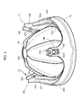
figure 3 shows an enlarged view of embodiments, and -
figure 4 is a partial view, shown on an enlarged scale, corresponding to the arrow IV shown infigure 3 . - In the following description, various specific details aimed at providing a fuller understanding of various exemplary embodiments are explained. The embodiments may be implemented without one or more of the specific details or using other methods, components, materials, etc. In other cases, known structures, materials or operations are not shown or described in detail so that the various aspects of the embodiments may be understood more clearly.
- The reference to "an embodiment" in the context of this description indicates that a particular configuration, structure or feature described in relation to the embodiment is included in at least one embodiment. Therefore, phrases such as "in one embodiment", which may occur at various points in this description, do not necessarily refer to the same embodiment. Moreover, particular forms, structures or features may be combined in any suitable manner in one or more embodiments.
- The reference signs used here are provided solely for the sake of convenience and therefore do not define the scope of protection or ambit of the embodiments.
- In the figures, the reference sign L denotes a lighting device as a whole.
- In the exemplary embodiment under consideration here, which is so designed, the device L can be present in the form of what is termed a "spotlight", which can use, as the light radiation source, an LED source.
- In various embodiments, the device L can include a
body 10, for example a tubular and cylindrical body, on which anoptical assembly 12 can be mounted. - The
optical assembly 12 is intended to make it possible for a light radiation source, for example an LED source, to be mounted on the device L. - As a result, the light radiation source can be mounted on the embodiments even only with a view to the installation, and the
optical assembly 12 can be used in association with light radiation sources of varying types. - In various embodiments, the
optical assembly 12 can include areflector 14 having a cup-shaped general form (for example a paraboloid shape), with a bottom portion (identified for example by an opening 14a), where it is possible to mount (in accordance with known parameters) a light radiation source, for example of the LED type, and amouth portion 14b, through which the light radiation produced by the source located at theportion 14a is projected towards the outside of the reflector. - The
mouth part 14b of the reflector is delimited by a peripheral rim, along which, in various embodiments, aflange 140 protruding towards the outside of the mouth rim of thereflector 14 can extend. - Reflectors of the type described are known in the art, and it is therefore not necessary to provide a detailed description at this point.
- Similar considerations on the whole also apply concerning a
screen 16, which rests peripherally on the rim of themouth part 14b of thereflector 14. - In various embodiments, the
screen 16 can have a generally planar shape. - In various embodiments, the
screen 16 can perform one or more functions. - In various embodiments, the
screen 16 can perform a protective function. - In various embodiments, the
screen 16 can perform optical functions of varying types, for example as a filter which has an effect on the chromatic features of the radiation emitted by the light source L (for example to produce radiations with defined color or color temperature features). - In various embodiments, the
screen 16 can be configured in the form of a lens, for example a Fresnel lens. - In the examples under consideration here, the
reflector 14 and thescreen 16 have a generally circular shape, this feature also being identifiable in thebody 10 of the lighting device L and in the overall shape of the other elements which will be described hereinbelow. It is moreover clear that this circular shape does not have a binding character for the embodiments. - In various embodiments, the screen 16 (which can be defined, whatever its function, as a totally or partially light-permeable screen) can rest peripherally on the
mouth portion 14b of thereflector 14, for example on the flange 140 (if present), and be kept in this position by being arranged sandwiched between thereflector 14 and afront ring 18, which can constitute, in various embodiments, a receiving frame for thescreen 16. - In various embodiments, the
front ring 18 can have an annularinner surface 18a, on which thescreen 16 rests peripherally and is hence interposed between theinner surface 18a and themouth portion 14b of thereflector 14. - In various embodiments, the
front ring 18 can have a plurality ofcusp formations 18b (for example, in the embodiments shown here, three cusp formations, although the number may be different). - In various embodiments, the
cusp formations 18b can be arranged at regular angular intervals along the outline of thering 18. For example, in the example under consideration here, which is so designed, there are threecusp formations 18b spaced apart angularly by 120° with respect to one another. - In various embodiments, the
cusp formations 18b can extend starting from theinner surface 18a of thering 18 in such a way as to surround thereflector 14, while moreover surrounding thescreen 16 interposed between themouth part 14b of thereflector 14 and theinner surface 18a of thefront ring 18. - The
reference numeral 20 denotes a spring which can be coupled to thefront ring 18 in such a way as to elastically urge thereflector 14 and thescreen 16 to rest against theinner surface 18a of thefront ring 18 so as to "keep together" the various elements which make up theoptical assembly 12. - In various embodiments, the
spring 20 can be formed by a single wire-like element (for example a continuous metallic wire) which is closed like a ring and has a cusped shape which, as a whole, reproduces the likewise cusped shape of the side of thefront ring 18 which faces towards thereflector 14. - In various embodiments, the
spring 20 can thus have threecusps 20a which are also spaced apart at regular intervals angularly by 120° with respect to one another. - As already mentioned in relation to the
cusp formations 18b of thefront ring 18, in various embodiments the number ofcusps 20a of thespring 20 may also differ from three. - In various embodiments, the
front ring 18 and thespring 20 can have differing numbers ofcusp formations 18b and ofcusps 20a. - Whatever the choice made, in various embodiments at least some of the
cusps 20a of thespring 20 can be aligned withcusp formations 18b of thefront ring 18. This as a whole so as to realize a coupling between thespring 20 and thefront ring 18 so as to ensure that thespring 20 performs the action of urging thereflector 14 and thescreen 16 towards thefront ring 18. - In various embodiments, this coupling can be realized by virtue of the fact that the
cusps 20a of thespring 20 havedistal portions 200 which are folded towards the outside of the spring 20 (which can have a general annular shape) in such a way that the distal ends 200 of thecusps 20a of thespring 20 can be inserted into correspondingreceiving cavities 180 provided in thecusp parts 18b of thefront ring 18, for example in the vicinity of the distal ends thereof. - In various embodiments, the general elasticity of the
spring 20 can ensure that thedistal ends 200 engage in thecavities 180 by means of a snap-like coupling, with thedistal ends 200 of thespring 20 advancing radially within the cavities 120 until a coupled state is reached, said distal ends then being able to be disengaged with respect to said position by means of a recall action in a radially inner direction of therespective cusp 20a. - In various embodiments, the
spring 20 can include a plurality ofloop parts 20b, each of which extends festoon-like (this fact can be appreciated for example infigure 3 ) so as to act on the reflector 14 (for example on the flange 140) so as to urge it (together with the screen 16) towards theinner surface 18a of thefront ring 18. - In various embodiments, as shown by way of example in
figures 1 and2 , thefront ring 18 can have a peripheral opening 22 (of a generally annular shape, for example distributed in a number of adjacent openings in an arcuate form) which surrounds theinner surface 18a, allowing for the flow of ventilation air through thering 18. - In various embodiments, as it is realized in such a way as to surround the
inner surface 18a of thering 18, the ventilation opening 22 is radially on the outside with respect to the outline both of thescreen 16 and of the reflector 14 (in particular with respect to the flange 140), and can thus allow for a flow of ventilation air with respect to the inside of the lighting device L. - In various embodiments, the coupling of the
optical assembly 12 to thebody 10 of the lighting device L can be effected by exploiting thecusp formations 18b. - In various embodiments, this can be achieved by providing, at the distal ends of the
cusp formations 18b, recesses ornotches 24 directed axially away from thesurface 18a. This is done in such a way as to form, at the ends of thecusp formations 18b, pincer-like elements (which can have features of spring-like pincers, for example when thefront ring 18 is made of an elastic material such as a plastic material) which can be coupled, for example in a gripping relationship, to nuclei orbeads 24a mounted on thebody 10 of the lighting device. - In various embodiments, the nuclei or
beads 24a can be inserted/screwed into the ends of channel-like ribs 10a provided in thebody 10. - Of course, without affecting the principle of the invention, the constructional details and embodiments may vary, also significantly, with respect to that illustrated here purely by way of non-limiting example, without thereby departing from the scope of protection. This scope of protection is defined by the accompanying claims.
Claims (9)
- An optical assembly (12) for lighting sources (L), including:- a cup-shaped reflector (14) having a bottom portion (14a) for mounting a light radiation source and a mouth portion (14b) for projecting the light radiation, the mouth portion (14b) having a peripheral rim (140),- a light-permeable screen (16) peripherally resting on the rim (140) of the mouth portion (14b) of the reflector (14),- a front ring (18) forming a receiving frame for the screen (16) to arrange the screen (16) sandwiched between the reflector (14) and an annular inner side (18a) of the front ring (18), the front ring (18) having a plurality of cusp formations (18b) protruding from said annular inner side (18a) to surround the reflector (14), and- an annular assembly spring (20) coupleable to the front ring (18) to urge the reflector (14) and the screen (16) towards the annular inner side (18a) of the front ring (18), the assembly spring (20) having a plurality of cusps (20a) having distal ends (200) coupleable to the cusp formations (18b) of the front ring (18).
- The optical assembly as claimed in claim 1, wherein the assembly spring (20) has loop portions (20b) extending, preferably festoon-like, between pairs of cusps (20a) of the assembly spring (20) to urge the reflector (14) and the screen (16) towards the annular inner side (18a) of the front ring (18).
- The optical assembly as claimed in claim 1 or claim 2, wherein the distal ends (200) of the cusps (20a) of the assembly spring (20) are bent radially outwardly to engage respective cavities (180) in the cusp formations (18b) of the front ring (18).
- The optical assembly as claimed in any of the preceding claims, wherein the assembly spring (20) includes a wire-like body shaped to include a plurality of cusps (20a) and loop portions (20b) each extending festoon-like between a pair of cusps (20a).
- The optical assembly as claimed in any of the preceding claims, wherein the reflector (14) has an outwardly protruding flange (140) extending along the peripheral rim of the mouth portion (14b) with the assembly spring (20) acting on said flange (140) to urge the reflector (14) and the screen (16) towards the annular inner side (18a) of the front ring (18).
- The optical assembly as claimed in any of the preceding claims, wherein the screen (16) is a planar screen.
- The optical assembly as claimed in any of the preceding claims, wherein the cusp formations (18b) of the front ring (18) have coupling notches (24) for coupling to a body (10) of the lighting device (L).
- The optical assembly as claimed in claim 7, wherein the coupling notches (24) are directed axially away from the annular inner side (18a) of the front ring (18).
- The optical assembly as claimed in any of the preceding claims, wherein the front ring (18) has a peripheral annular ventilation opening (22) surrounding said annular inner side (18a).
Applications Claiming Priority (1)
| Application Number | Priority Date | Filing Date | Title |
|---|---|---|---|
| ITTO20120824 | 2012-09-24 |
Publications (3)
| Publication Number | Publication Date |
|---|---|
| EP2711621A2 true EP2711621A2 (en) | 2014-03-26 |
| EP2711621A3 EP2711621A3 (en) | 2014-06-18 |
| EP2711621B1 EP2711621B1 (en) | 2016-03-23 |
Family
ID=47018397
Family Applications (1)
| Application Number | Title | Priority Date | Filing Date |
|---|---|---|---|
| EP13182387.4A Not-in-force EP2711621B1 (en) | 2012-09-24 | 2013-08-30 | Optical assembly for lighting sources |
Country Status (1)
| Country | Link |
|---|---|
| EP (1) | EP2711621B1 (en) |
Family Cites Families (3)
| Publication number | Priority date | Publication date | Assignee | Title |
|---|---|---|---|---|
| GB1027873A (en) * | 1963-03-29 | 1966-04-27 | Meyer Manuf Co Ltd | Torch |
| US5215371A (en) * | 1991-10-21 | 1993-06-01 | Welch Allyn, Inc. | Lamp holder |
| DE4410192B4 (en) * | 1994-03-24 | 2004-07-01 | Erco Leuchten Gmbh | Fastening arrangement for a front attached to a light exit opening of a light housing of a spotlight base attachment part |
-
2013
- 2013-08-30 EP EP13182387.4A patent/EP2711621B1/en not_active Not-in-force
Non-Patent Citations (1)
| Title |
|---|
| None |
Also Published As
| Publication number | Publication date |
|---|---|
| EP2711621A3 (en) | 2014-06-18 |
| EP2711621B1 (en) | 2016-03-23 |
Similar Documents
| Publication | Publication Date | Title |
|---|---|---|
| US6502962B1 (en) | Cover assembly for a light | |
| CN103597274A (en) | Dual zone lighting apparatus | |
| US2430472A (en) | Lighting fixture | |
| CN109140371B (en) | Universal adapter device for vehicle headlights and headlight assembly comprising such a device | |
| JP2008098086A (en) | Light source lamp unit | |
| CN109477624B (en) | A lampshade, lamps and aircraft | |
| AU2019365599B2 (en) | Runway-embedded flash lighting device | |
| EP2711621B1 (en) | Optical assembly for lighting sources | |
| EP3543761A1 (en) | Device for condensing and changing light of mobile phone | |
| US20150167931A1 (en) | Process for equipping lighting sources, corresponding devices and assortment | |
| CN100543364C (en) | Spotlight lamp | |
| US3767913A (en) | Ventilated lamp guard | |
| CN106461199A (en) | Lighting device and luminaire | |
| CN103925560B (en) | Interchangeable Reflectors For Light Devices | |
| KR200483081Y1 (en) | Fixture for light cover | |
| CN108351082B (en) | Method for manufacturing design equipment for vehicles and lighting devices | |
| CN206226586U (en) | A kind of infrared lamp device and the CCTV camera with it | |
| US6905233B1 (en) | Light guard | |
| KR101425277B1 (en) | Lighting equipment lampshade | |
| KR101413631B1 (en) | A reflection cover for fluorescent lamp | |
| CN213420686U (en) | Light-transmitting protection device of LED lamp bead and lamp | |
| RU140140U1 (en) | FARA | |
| KR200484042Y1 (en) | Floodlight Locking Device | |
| US9909741B2 (en) | Watertight lighting fixture | |
| CN104613398B (en) | Automobile lamp |
Legal Events
| Date | Code | Title | Description |
|---|---|---|---|
| PUAI | Public reference made under article 153(3) epc to a published international application that has entered the european phase |
Free format text: ORIGINAL CODE: 0009012 |
|
| AK | Designated contracting states |
Kind code of ref document: A2 Designated state(s): AL AT BE BG CH CY CZ DE DK EE ES FI FR GB GR HR HU IE IS IT LI LT LU LV MC MK MT NL NO PL PT RO RS SE SI SK SM TR |
|
| AX | Request for extension of the european patent |
Extension state: BA ME |
|
| PUAL | Search report despatched |
Free format text: ORIGINAL CODE: 0009013 |
|
| AK | Designated contracting states |
Kind code of ref document: A3 Designated state(s): AL AT BE BG CH CY CZ DE DK EE ES FI FR GB GR HR HU IE IS IT LI LT LU LV MC MK MT NL NO PL PT RO RS SE SI SK SM TR |
|
| AX | Request for extension of the european patent |
Extension state: BA ME |
|
| RIC1 | Information provided on ipc code assigned before grant |
Ipc: F21V 19/00 20060101ALI20140514BHEP Ipc: F21V 17/16 20060101AFI20140514BHEP |
|
| 17P | Request for examination filed |
Effective date: 20141218 |
|
| RBV | Designated contracting states (corrected) |
Designated state(s): AL AT BE BG CH CY CZ DE DK EE ES FI FR GB GR HR HU IE IS IT LI LT LU LV MC MK MT NL NO PL PT RO RS SE SI SK SM TR |
|
| GRAP | Despatch of communication of intention to grant a patent |
Free format text: ORIGINAL CODE: EPIDOSNIGR1 |
|
| INTG | Intention to grant announced |
Effective date: 20150915 |
|
| GRAJ | Information related to disapproval of communication of intention to grant by the applicant or resumption of examination proceedings by the epo deleted |
Free format text: ORIGINAL CODE: EPIDOSDIGR1 |
|
| GRAR | Information related to intention to grant a patent recorded |
Free format text: ORIGINAL CODE: EPIDOSNIGR71 |
|
| GRAA | (expected) grant |
Free format text: ORIGINAL CODE: 0009210 |
|
| INTG | Intention to grant announced |
Effective date: 20160126 |
|
| AK | Designated contracting states |
Kind code of ref document: B1 Designated state(s): AL AT BE BG CH CY CZ DE DK EE ES FI FR GB GR HR HU IE IS IT LI LT LU LV MC MK MT NL NO PL PT RO RS SE SI SK SM TR |
|
| REG | Reference to a national code |
Ref country code: GB Ref legal event code: FG4D |
|
| REG | Reference to a national code |
Ref country code: CH Ref legal event code: EP |
|
| REG | Reference to a national code |
Ref country code: AT Ref legal event code: REF Ref document number: 783520 Country of ref document: AT Kind code of ref document: T Effective date: 20160415 |
|
| REG | Reference to a national code |
Ref country code: IE Ref legal event code: FG4D |
|
| REG | Reference to a national code |
Ref country code: DE Ref legal event code: R096 Ref document number: 602013005668 Country of ref document: DE |
|
| REG | Reference to a national code |
Ref country code: LT Ref legal event code: MG4D |
|
| REG | Reference to a national code |
Ref country code: NL Ref legal event code: MP Effective date: 20160323 |
|
| PG25 | Lapsed in a contracting state [announced via postgrant information from national office to epo] |
Ref country code: FI Free format text: LAPSE BECAUSE OF FAILURE TO SUBMIT A TRANSLATION OF THE DESCRIPTION OR TO PAY THE FEE WITHIN THE PRESCRIBED TIME-LIMIT Effective date: 20160323 Ref country code: GR Free format text: LAPSE BECAUSE OF FAILURE TO SUBMIT A TRANSLATION OF THE DESCRIPTION OR TO PAY THE FEE WITHIN THE PRESCRIBED TIME-LIMIT Effective date: 20160624 Ref country code: NO Free format text: LAPSE BECAUSE OF FAILURE TO SUBMIT A TRANSLATION OF THE DESCRIPTION OR TO PAY THE FEE WITHIN THE PRESCRIBED TIME-LIMIT Effective date: 20160623 Ref country code: HR Free format text: LAPSE BECAUSE OF FAILURE TO SUBMIT A TRANSLATION OF THE DESCRIPTION OR TO PAY THE FEE WITHIN THE PRESCRIBED TIME-LIMIT Effective date: 20160323 |
|
| REG | Reference to a national code |
Ref country code: FR Ref legal event code: PLFP Year of fee payment: 4 |
|
| PG25 | Lapsed in a contracting state [announced via postgrant information from national office to epo] |
Ref country code: LT Free format text: LAPSE BECAUSE OF FAILURE TO SUBMIT A TRANSLATION OF THE DESCRIPTION OR TO PAY THE FEE WITHIN THE PRESCRIBED TIME-LIMIT Effective date: 20160323 Ref country code: LV Free format text: LAPSE BECAUSE OF FAILURE TO SUBMIT A TRANSLATION OF THE DESCRIPTION OR TO PAY THE FEE WITHIN THE PRESCRIBED TIME-LIMIT Effective date: 20160323 Ref country code: NL Free format text: LAPSE BECAUSE OF FAILURE TO SUBMIT A TRANSLATION OF THE DESCRIPTION OR TO PAY THE FEE WITHIN THE PRESCRIBED TIME-LIMIT Effective date: 20160323 Ref country code: SE Free format text: LAPSE BECAUSE OF FAILURE TO SUBMIT A TRANSLATION OF THE DESCRIPTION OR TO PAY THE FEE WITHIN THE PRESCRIBED TIME-LIMIT Effective date: 20160323 Ref country code: RS Free format text: LAPSE BECAUSE OF FAILURE TO SUBMIT A TRANSLATION OF THE DESCRIPTION OR TO PAY THE FEE WITHIN THE PRESCRIBED TIME-LIMIT Effective date: 20160323 |
|
| PG25 | Lapsed in a contracting state [announced via postgrant information from national office to epo] |
Ref country code: PL Free format text: LAPSE BECAUSE OF FAILURE TO SUBMIT A TRANSLATION OF THE DESCRIPTION OR TO PAY THE FEE WITHIN THE PRESCRIBED TIME-LIMIT Effective date: 20160323 Ref country code: EE Free format text: LAPSE BECAUSE OF FAILURE TO SUBMIT A TRANSLATION OF THE DESCRIPTION OR TO PAY THE FEE WITHIN THE PRESCRIBED TIME-LIMIT Effective date: 20160323 Ref country code: IS Free format text: LAPSE BECAUSE OF FAILURE TO SUBMIT A TRANSLATION OF THE DESCRIPTION OR TO PAY THE FEE WITHIN THE PRESCRIBED TIME-LIMIT Effective date: 20160723 |
|
| PG25 | Lapsed in a contracting state [announced via postgrant information from national office to epo] |
Ref country code: ES Free format text: LAPSE BECAUSE OF FAILURE TO SUBMIT A TRANSLATION OF THE DESCRIPTION OR TO PAY THE FEE WITHIN THE PRESCRIBED TIME-LIMIT Effective date: 20160323 Ref country code: RO Free format text: LAPSE BECAUSE OF FAILURE TO SUBMIT A TRANSLATION OF THE DESCRIPTION OR TO PAY THE FEE WITHIN THE PRESCRIBED TIME-LIMIT Effective date: 20160323 Ref country code: SK Free format text: LAPSE BECAUSE OF FAILURE TO SUBMIT A TRANSLATION OF THE DESCRIPTION OR TO PAY THE FEE WITHIN THE PRESCRIBED TIME-LIMIT Effective date: 20160323 Ref country code: PT Free format text: LAPSE BECAUSE OF FAILURE TO SUBMIT A TRANSLATION OF THE DESCRIPTION OR TO PAY THE FEE WITHIN THE PRESCRIBED TIME-LIMIT Effective date: 20160725 Ref country code: CZ Free format text: LAPSE BECAUSE OF FAILURE TO SUBMIT A TRANSLATION OF THE DESCRIPTION OR TO PAY THE FEE WITHIN THE PRESCRIBED TIME-LIMIT Effective date: 20160323 Ref country code: SM Free format text: LAPSE BECAUSE OF FAILURE TO SUBMIT A TRANSLATION OF THE DESCRIPTION OR TO PAY THE FEE WITHIN THE PRESCRIBED TIME-LIMIT Effective date: 20160323 |
|
| PG25 | Lapsed in a contracting state [announced via postgrant information from national office to epo] |
Ref country code: BE Free format text: LAPSE BECAUSE OF FAILURE TO SUBMIT A TRANSLATION OF THE DESCRIPTION OR TO PAY THE FEE WITHIN THE PRESCRIBED TIME-LIMIT Effective date: 20160323 |
|
| REG | Reference to a national code |
Ref country code: DE Ref legal event code: R097 Ref document number: 602013005668 Country of ref document: DE |
|
| PLBE | No opposition filed within time limit |
Free format text: ORIGINAL CODE: 0009261 |
|
| STAA | Information on the status of an ep patent application or granted ep patent |
Free format text: STATUS: NO OPPOSITION FILED WITHIN TIME LIMIT |
|
| PG25 | Lapsed in a contracting state [announced via postgrant information from national office to epo] |
Ref country code: DK Free format text: LAPSE BECAUSE OF FAILURE TO SUBMIT A TRANSLATION OF THE DESCRIPTION OR TO PAY THE FEE WITHIN THE PRESCRIBED TIME-LIMIT Effective date: 20160323 |
|
| PG25 | Lapsed in a contracting state [announced via postgrant information from national office to epo] |
Ref country code: BG Free format text: LAPSE BECAUSE OF FAILURE TO SUBMIT A TRANSLATION OF THE DESCRIPTION OR TO PAY THE FEE WITHIN THE PRESCRIBED TIME-LIMIT Effective date: 20160623 |
|
| 26N | No opposition filed |
Effective date: 20170102 |
|
| PG25 | Lapsed in a contracting state [announced via postgrant information from national office to epo] |
Ref country code: MC Free format text: LAPSE BECAUSE OF FAILURE TO SUBMIT A TRANSLATION OF THE DESCRIPTION OR TO PAY THE FEE WITHIN THE PRESCRIBED TIME-LIMIT Effective date: 20160323 |
|
| PG25 | Lapsed in a contracting state [announced via postgrant information from national office to epo] |
Ref country code: SI Free format text: LAPSE BECAUSE OF FAILURE TO SUBMIT A TRANSLATION OF THE DESCRIPTION OR TO PAY THE FEE WITHIN THE PRESCRIBED TIME-LIMIT Effective date: 20160323 |
|
| REG | Reference to a national code |
Ref country code: IE Ref legal event code: MM4A |
|
| PG25 | Lapsed in a contracting state [announced via postgrant information from national office to epo] |
Ref country code: IE Free format text: LAPSE BECAUSE OF NON-PAYMENT OF DUE FEES Effective date: 20160830 |
|
| REG | Reference to a national code |
Ref country code: FR Ref legal event code: PLFP Year of fee payment: 5 |
|
| PG25 | Lapsed in a contracting state [announced via postgrant information from national office to epo] |
Ref country code: LU Free format text: LAPSE BECAUSE OF NON-PAYMENT OF DUE FEES Effective date: 20160830 |
|
| PGFP | Annual fee paid to national office [announced via postgrant information from national office to epo] |
Ref country code: CH Payment date: 20170821 Year of fee payment: 5 Ref country code: DE Payment date: 20170822 Year of fee payment: 5 Ref country code: IT Payment date: 20170828 Year of fee payment: 5 Ref country code: GB Payment date: 20170822 Year of fee payment: 5 Ref country code: FR Payment date: 20170822 Year of fee payment: 5 |
|
| REG | Reference to a national code |
Ref country code: CH Ref legal event code: NV Representative=s name: BOVARD AG PATENT- UND MARKENANWAELTE, CH Ref country code: CH Ref legal event code: PUEA Owner name: OSRAM GMBH, DE Free format text: FORMER OWNER: OSRAM GMBH, IT |
|
| REG | Reference to a national code |
Ref country code: AT Ref legal event code: PC Ref document number: 783520 Country of ref document: AT Kind code of ref document: T Owner name: OSRAM GMBH, DE Effective date: 20180125 |
|
| REG | Reference to a national code |
Ref country code: GB Ref legal event code: 732E Free format text: REGISTERED BETWEEN 20180315 AND 20180326 |
|
| REG | Reference to a national code |
Ref country code: FR Ref legal event code: TP Owner name: OSRAM GMBH, DE Effective date: 20180411 |
|
| PG25 | Lapsed in a contracting state [announced via postgrant information from national office to epo] |
Ref country code: HU Free format text: LAPSE BECAUSE OF FAILURE TO SUBMIT A TRANSLATION OF THE DESCRIPTION OR TO PAY THE FEE WITHIN THE PRESCRIBED TIME-LIMIT; INVALID AB INITIO Effective date: 20130830 Ref country code: CY Free format text: LAPSE BECAUSE OF FAILURE TO SUBMIT A TRANSLATION OF THE DESCRIPTION OR TO PAY THE FEE WITHIN THE PRESCRIBED TIME-LIMIT Effective date: 20160323 |
|
| PG25 | Lapsed in a contracting state [announced via postgrant information from national office to epo] |
Ref country code: MK Free format text: LAPSE BECAUSE OF FAILURE TO SUBMIT A TRANSLATION OF THE DESCRIPTION OR TO PAY THE FEE WITHIN THE PRESCRIBED TIME-LIMIT Effective date: 20160323 Ref country code: MT Free format text: LAPSE BECAUSE OF NON-PAYMENT OF DUE FEES Effective date: 20160831 |
|
| PG25 | Lapsed in a contracting state [announced via postgrant information from national office to epo] |
Ref country code: TR Free format text: LAPSE BECAUSE OF FAILURE TO SUBMIT A TRANSLATION OF THE DESCRIPTION OR TO PAY THE FEE WITHIN THE PRESCRIBED TIME-LIMIT Effective date: 20160323 Ref country code: AL Free format text: LAPSE BECAUSE OF FAILURE TO SUBMIT A TRANSLATION OF THE DESCRIPTION OR TO PAY THE FEE WITHIN THE PRESCRIBED TIME-LIMIT Effective date: 20160323 |
|
| REG | Reference to a national code |
Ref country code: AT Ref legal event code: UEP Ref document number: 783520 Country of ref document: AT Kind code of ref document: T Effective date: 20160323 |
|
| REG | Reference to a national code |
Ref country code: DE Ref legal event code: R119 Ref document number: 602013005668 Country of ref document: DE |
|
| REG | Reference to a national code |
Ref country code: CH Ref legal event code: PL |
|
| GBPC | Gb: european patent ceased through non-payment of renewal fee |
Effective date: 20180830 |
|
| PG25 | Lapsed in a contracting state [announced via postgrant information from national office to epo] |
Ref country code: CH Free format text: LAPSE BECAUSE OF NON-PAYMENT OF DUE FEES Effective date: 20180831 Ref country code: LI Free format text: LAPSE BECAUSE OF NON-PAYMENT OF DUE FEES Effective date: 20180831 |
|
| PG25 | Lapsed in a contracting state [announced via postgrant information from national office to epo] |
Ref country code: DE Free format text: LAPSE BECAUSE OF NON-PAYMENT OF DUE FEES Effective date: 20190301 Ref country code: IT Free format text: LAPSE BECAUSE OF NON-PAYMENT OF DUE FEES Effective date: 20180830 |
|
| PG25 | Lapsed in a contracting state [announced via postgrant information from national office to epo] |
Ref country code: FR Free format text: LAPSE BECAUSE OF NON-PAYMENT OF DUE FEES Effective date: 20180831 |
|
| REG | Reference to a national code |
Ref country code: AT Ref legal event code: MM01 Ref document number: 783520 Country of ref document: AT Kind code of ref document: T Effective date: 20180830 |
|
| PG25 | Lapsed in a contracting state [announced via postgrant information from national office to epo] |
Ref country code: GB Free format text: LAPSE BECAUSE OF NON-PAYMENT OF DUE FEES Effective date: 20180830 |
|
| PG25 | Lapsed in a contracting state [announced via postgrant information from national office to epo] |
Ref country code: AT Free format text: LAPSE BECAUSE OF NON-PAYMENT OF DUE FEES Effective date: 20180830 |