EP2711614A2 - Luminaire - Google Patents
Luminaire Download PDFInfo
- Publication number
- EP2711614A2 EP2711614A2 EP13173641.5A EP13173641A EP2711614A2 EP 2711614 A2 EP2711614 A2 EP 2711614A2 EP 13173641 A EP13173641 A EP 13173641A EP 2711614 A2 EP2711614 A2 EP 2711614A2
- Authority
- EP
- European Patent Office
- Prior art keywords
- surface cover
- light
- luminaire
- transmitted
- optical member
- Prior art date
- Legal status (The legal status is an assumption and is not a legal conclusion. Google has not performed a legal analysis and makes no representation as to the accuracy of the status listed.)
- Withdrawn
Links
Images





Classifications
-
- F—MECHANICAL ENGINEERING; LIGHTING; HEATING; WEAPONS; BLASTING
- F21—LIGHTING
- F21S—NON-PORTABLE LIGHTING DEVICES; SYSTEMS THEREOF; VEHICLE LIGHTING DEVICES SPECIALLY ADAPTED FOR VEHICLE EXTERIORS
- F21S8/00—Lighting devices intended for fixed installation
- F21S8/04—Lighting devices intended for fixed installation intended only for mounting on a ceiling or the like overhead structures
-
- F—MECHANICAL ENGINEERING; LIGHTING; HEATING; WEAPONS; BLASTING
- F21—LIGHTING
- F21V—FUNCTIONAL FEATURES OR DETAILS OF LIGHTING DEVICES OR SYSTEMS THEREOF; STRUCTURAL COMBINATIONS OF LIGHTING DEVICES WITH OTHER ARTICLES, NOT OTHERWISE PROVIDED FOR
- F21V3/00—Globes; Bowls; Cover glasses
-
- F—MECHANICAL ENGINEERING; LIGHTING; HEATING; WEAPONS; BLASTING
- F21—LIGHTING
- F21V—FUNCTIONAL FEATURES OR DETAILS OF LIGHTING DEVICES OR SYSTEMS THEREOF; STRUCTURAL COMBINATIONS OF LIGHTING DEVICES WITH OTHER ARTICLES, NOT OTHERWISE PROVIDED FOR
- F21V3/00—Globes; Bowls; Cover glasses
- F21V3/04—Globes; Bowls; Cover glasses characterised by materials, surface treatments or coatings
- F21V3/06—Globes; Bowls; Cover glasses characterised by materials, surface treatments or coatings characterised by the material
- F21V3/062—Globes; Bowls; Cover glasses characterised by materials, surface treatments or coatings characterised by the material the material being plastics
-
- F—MECHANICAL ENGINEERING; LIGHTING; HEATING; WEAPONS; BLASTING
- F21—LIGHTING
- F21Y—INDEXING SCHEME ASSOCIATED WITH SUBCLASSES F21K, F21L, F21S and F21V, RELATING TO THE FORM OR THE KIND OF THE LIGHT SOURCES OR OF THE COLOUR OF THE LIGHT EMITTED
- F21Y2103/00—Elongate light sources, e.g. fluorescent tubes
- F21Y2103/10—Elongate light sources, e.g. fluorescent tubes comprising a linear array of point-like light-generating elements
-
- F—MECHANICAL ENGINEERING; LIGHTING; HEATING; WEAPONS; BLASTING
- F21—LIGHTING
- F21Y—INDEXING SCHEME ASSOCIATED WITH SUBCLASSES F21K, F21L, F21S and F21V, RELATING TO THE FORM OR THE KIND OF THE LIGHT SOURCES OR OF THE COLOUR OF THE LIGHT EMITTED
- F21Y2115/00—Light-generating elements of semiconductor light sources
- F21Y2115/10—Light-emitting diodes [LED]
Definitions
- a luminaire 1 includes a light-emitting element 12, a side surface cover 6, a lower surface cover 7, a diffuser 9, and a prism 7b, which is an example of an optical member.
- the light-emitting element 12 emits light.
- the side surface cover 6 is arranged a predetermined distance from the light-emitting element 12.
- the light emitted by the light-emitting element 12 is transmitted through the side surface cover 6.
- the lower surface cover 7 is provided at the lower end of the side surface cover 6.
- the light emitted by the light-emitting element 12 is transmitted through the lower surface cover 7.
- the diffuser 9 is a member provided between the lower surface cover 7 and the light-emitting element 12 to diffuse the light emitted by the light-emitting element.
- the prism 7b adjusts a traveling direction of the light transmitted through the side surface cover 6 to be different from a traveling direction of the light emitted by the light-emitting element 12 and transmitted through the lower surface cover 7.
- an angle formed by a straight line 80, which connects a lower end 6b of the side surface cover 6 and a point 9b on the diffuser 9 most distant from the lower end 6b of the side surface cover 6, and a direction 9a perpendicular to a planar shape of the diffuser 9 is an angle equal to or larger than 5 degrees and equal to or smaller than 30 degrees.
- the light diffused or reflected by the diffuser 9 is transmitted through the side surface cover 6.
- the luminaire 1 according to the embodiment explained below further includes an attachment member 2 for attaching the luminaire 1 to the ceiling.
- the prism 7b adjusts the traveling direction of the light transmitted through the side surface cover 6 such that the light transmitted through the side surface cover 6 is irradiated on the ceiling.
- the prism 7b adjusts the traveling direction of the light transmitted through the side surface cover 6 such that the light is irradiated on the ceiling in a traveling direction at an angle equal to or larger than 40 degrees and equal to or smaller than 90 degrees with respect to a direction perpendicular to the ceiling.
- a ratio of an amount of the light transmitted through the lower surface cover 7 and an amount of the light adjusted by the prism 7b is in a range of 1:9 to 2:8.
- a hollow 6a is formed in a part of the side surface cover 6.
- a protrusion 7c on the prism 7b is configured to fit in the hollow 6a by which the prism 7b to be attached to the side surface cover 6.
- the lower surface cover 7 and the prism 7b are integrally molded.
- the lower surface cover 7, the side surface cover 6, the prism 7b, and the diffuser 9 may be integrally molded.
- the luminaire 1 includes a plurality of the side surface covers 6 and the prism 7b is provided on the side surface cover 6 that is located on the outermost side among the plurality of side surface covers 6.
- the prism 7b may be provided in each of the plurality of side surface covers 6.
- the prism is formed of a material containing acrylic resin or polycarbonate resin.
- FIG. 1 is a perspective view of an external appearance example of the luminaire 1 according to the embodiment.
- FIG. 2 is a sectional view of the luminaire shown in FIG. 1 .
- reference numeral 1 denotes a luminaire fixture for the ceiling or the like.
- the luminaire 1 shown in FIGS. 1 and 2 is, for example, a luminaire set on an indoor ceiling.
- the luminaire 1 shown in FIGS. 1 and 2 lights the downward direction and the upward direction shown in FIGS. 1 and 2 by causing, for example, a light-emitting element such as an LED to emit light.
- the luminaire 1 lights the floor and the ceiling in the room.
- the luminaire 1 includes the attachment member 2, a reflector 3, end plates 4, the side surface covers 6, and the lower surface cover 7.
- the attachment member 2 is attached to the indoor ceiling using a plurality of screws not shown in the figure. Consequently, the luminaire 1 is attached and fixed to the ceiling.
- a lighting circuit 5 is provided in a space formed by the reflector 3, the end plates 4, and the attachment member 2.
- the lighting circuit 5 receives a commercial alternating-current power supply, generates a direct-current output, and supplies the direct-current output to the light-emitting elements 12 of a light-emitting module 10 explained below.
- the side surface covers 6 are members formed of a material containing acrylic resin or polycarbonate resin and configured to transmit the lights emitted by the light-emitting elements 12 and lights diffused or reflected by the diffuser 9 explained below.
- the hollows 6a in which the protrusions 7c explained below are fit are formed in the side surface covers 6.
- the diffuser 9 is attached to the hollows 6a. As shown in FIG. 2 , the side surface covers 6 are arranged a predetermined space apart from the light-emitting elements 12.
- the lower surface cover 7 is a member formed of a material containing acrylic resin or polycarbonate resin and configured to transmit the lights diffused by the diffuser 9 among the lights emitted by the light-emitting elements 12. As shown in FIG. 2 , the lower surface cover 7 is formed to cover the side surface covers 6 and is attached to the attachment member 2.
- the lower surface cover 7 includes the side surface sections 7a configured to cover the side surface covers 6. Since the side surface sections 7a transmit lights, the lights transmitted through the side surface covers 6 are transmitted through the side surface sections 7a as well. That is, the side surface sections 7a transmit the lights emitted by the light-emitting elements and transmitted through the side surface covers 6 and the lights diffused or reflected by the diffuser.
- the prisms 7b adjust the traveling directions of the lights transmitted through the side surface covers 6 and the side surface sections 7a such that the lights transmitted through the side surface covers 6 and the side surface sections 7a are irradiated on the ceiling.
- the prisms 7b are explained below.
- the plurality of prisms 7b may be respectively provided in all of the plurality of side surface covers 6. In this case, the lights from the prisms 7b adjacent to the reflector 3 travel toward the reflector 3. Therefore, a larger amount of the lights travel toward the reflector 3. Therefore, it is possible to further improve a sense of brightness of a space and provide a more comfortable lighting space for a person.
- the light-emitting module 10 is provided in the space formed by the lower surface cover 7 and the attachment member 2.
- FIG. 4 is a diagram of an external appearance example of the light-emitting module. As shown in FIG. 4 , the light-emitting module 10 includes a plurality of substrates 11 and the plurality of light-emitting elements 12 respectively mounted on the plurality of substrates 11. The substrates 11 are attached to the attachment member 2. Consequently, the light-emitting module 10 is attached to the attachment member 2.
- the diffuser 9 having transmittance for setting a ratio of an amount of the lights transmitted through the lower surface cover 7 and an amount of the lights adjusted by the prisms 7b and irradiated on the ceiling to a ratio in a range of 1:9 to 2:8 is used.
- the diffuser 9 is provided in a position where such a ratio is obtained.
- FIG. 6 is a diagram showing an example of the positional relation between the diffuser 9 and the lower surface cover 7.
- FIG. 6 is a sectional view of the luminaire 1.
- an angle ⁇ formed by the straight line 80, which connects the lower end 6b of the side surface cover 6 on which the prisms 7b are provided and the point 9b, and the direction 9a perpendicular to the planar shape of the diffuser 9 is an angle equal to or larger than 5 degrees and equal to or smaller than 30 degrees.
- the point 9b is a point on the diffuser 9 most distant from the lower end 6b on a cross section including the lower end 6b. That is, the point 9b is a point on the diffuser 9 most distant from the lower end 6b on a plane including the lower end 6b.
- the luminaire 1 includes the light-emitting elements 12, the side surface covers 6, the lower surface cover 7, the diffuser 9, and the prisms 7b, which are an example of optical members.
- the light-emitting elements 12 emit lights.
- the side surface covers 6 are arranged at the predetermined distance from the light-emitting elements 12.
- the light emitted by the light-emitting element 12 is transmitted through the side surface cover 6.
- the lower surface cover 7 is provided at the lower ends of the side surface covers 6.
- the light emitted by the light-emitting element 12 is transmitted through the lower surface cover 7.
- the diffuser 9 is a member provided between the lower surface cover 7 and the light-emitting elements 12 to diffuse the lights emitted by the light-emitting element.
- the angle ⁇ formed by the straight line 80, which connects the lower end 6b of the side surface cover 6 and the point 9b on the diffuser 9 most distant from the lower end 6b of the side surface cover 6, and the direction 9a perpendicular to the planar shape of the diffuser 9 is an angle equal to or larger than 5 degrees and equal to or smaller than 30 degrees.
- the lights diffused or reflected by the diffuser 9 are transmitted through the side surface cover 6.
- the luminaire 1 according to this embodiment includes the attachment member 2 for attaching the luminaire 1 to the ceiling.
- the prisms 7b adjust the traveling directions of the lights transmitted through the side surface covers 6 such that the lights transmitted through the side surface covers 6 are irradiated on the ceiling. Therefore, with the luminaire 1 according to this embodiment, the lights are irradiated on the ceiling as well. Therefore, with the luminaire 1 according to this embodiment, it is possible to improve a sense of brightness of a space and provide a comfortable lighting space for a person.
- the prisms 7b adjust the traveling directions of the lights transmitted through the side surface covers 6 such that the lights are irradiated on the ceiling in the traveling directions at an angle equal to or larger than 40 degrees and equal to or smaller than 90 degrees with respect to the direction perpendicular to the ceiling.
- the lower surface cover 7 and the prisms 7b are integrally molded. Consequently, the lower surface cover 7 and the prisms 7b can be provided as one component. Therefore, it is possible to reduce the number of components.
- the side surface covers 6, the lower surface cover 7, and the prisms 7b may be integrally molded. Consequently, the side surface covers 6, the lower surface cover 7, and the prisms 7b can be provided as one component. Therefore, it is possible to reduce the number of components.
- the prisms 7b are provided on the side surface covers 6 that is located on the outermost side among the plurality of side surface covers 6. Consequently, the prisms 7b are provided only on the side surface covers 6 present in positions where lights can be irradiated on the ceiling. Therefore, the number of the prisms 7b used for making the ceiling bright can be minimized.
- the prisms 7b are formed of a material containing acrylic resin or polycarbonate resin.
Landscapes
- Engineering & Computer Science (AREA)
- General Engineering & Computer Science (AREA)
- Non-Portable Lighting Devices Or Systems Thereof (AREA)
- Optical Elements Other Than Lenses (AREA)
Abstract
Description
- Embodiments described herein relate generally to a luminaire.
- A luminaire including semiconductor light-emitting elements such as LEDs (Light Emitting Diodes) as light sources is used. As an example of such a luminaire, there is a luminaire in which a diffuser is proved at the lower ends of side surface covers.
- However, in such a luminaire, light is diffused to a wide area by the diffuser of the luminaire. Therefore, for a person located in a wide area of a room where the luminaire is set, the light from the luminaire is glaring.
- Even if the light emitted from the luminaire is glaring, if a luminaire that emits less bright light is provided in the room, a sense of brightness decreases for the person in the room.
-
-
FIG. 1 is a perspective view of an external appearance example of a luminaire according to an embodiment; -
FIG. 2 is a sectional view of the luminaire shown inFIG. 1 ; -
FIG. 3 is a diagram of an external appearance example of a diffuser; -
FIG. 4 is a diagram of an external appearance example of a light-emitting module; -
FIG. 5 is a sectional view of a portion covered with a lower surface cover on the left side inFIG. 1 ; -
FIG. 6 is a diagram of an example of a positional relation between the diffuser and the lower surface cover; -
FIG. 7 is a diagram for explaining an example of an effect of the luminaire according to the embodiment; and -
FIG. 8 is a diagram for explaining an example of an effect of the luminaire according to the embodiment. - A luminaire 1 according to an embodiment explained below includes a light-emitting
element 12, aside surface cover 6, alower surface cover 7, adiffuser 9, and aprism 7b, which is an example of an optical member. The light-emittingelement 12 emits light. Theside surface cover 6 is arranged a predetermined distance from the light-emittingelement 12. The light emitted by the light-emittingelement 12 is transmitted through theside surface cover 6. Thelower surface cover 7 is provided at the lower end of theside surface cover 6. The light emitted by the light-emittingelement 12 is transmitted through thelower surface cover 7. Thediffuser 9 is a member provided between thelower surface cover 7 and the light-emittingelement 12 to diffuse the light emitted by the light-emitting element. Theprism 7b adjusts a traveling direction of the light transmitted through theside surface cover 6 to be different from a traveling direction of the light emitted by the light-emittingelement 12 and transmitted through thelower surface cover 7. - In the luminaire 1 according to an embodiment explained below, an angle formed by a
straight line 80, which connects alower end 6b of theside surface cover 6 and apoint 9b on thediffuser 9 most distant from thelower end 6b of theside surface cover 6, and adirection 9a perpendicular to a planar shape of thediffuser 9 is an angle equal to or larger than 5 degrees and equal to or smaller than 30 degrees. - In the luminaire 1 according to the embodiment explained below, the light diffused or reflected by the
diffuser 9 is transmitted through theside surface cover 6. - The luminaire 1 according to the embodiment explained below further includes an
attachment member 2 for attaching the luminaire 1 to the ceiling. In the luminaire 1, theprism 7b adjusts the traveling direction of the light transmitted through theside surface cover 6 such that the light transmitted through theside surface cover 6 is irradiated on the ceiling. - In the luminaire 1 according to the embodiment explained below, the
prism 7b adjusts the traveling direction of the light transmitted through theside surface cover 6 such that the light is irradiated on the ceiling in a traveling direction at an angle equal to or larger than 40 degrees and equal to or smaller than 90 degrees with respect to a direction perpendicular to the ceiling. - In the luminaire 1 according to the embodiment explained below, a refractive index of the
prism 7b is equal to or larger than 1.45 and equal to or smaller than 1.65. - In the luminaire 1 according to the embodiment explained below, a ratio of an amount of the light transmitted through the
lower surface cover 7 and an amount of the light adjusted by theprism 7b is in a range of 1:9 to 2:8. - In the luminaire 1 according to the embodiment explained below, a hollow 6a is formed in a part of the
side surface cover 6. In the luminaire 1, aprotrusion 7c on theprism 7b is configured to fit in the hollow 6a by which theprism 7b to be attached to theside surface cover 6. - In the luminaire 1 according to the embodiment explained below, the
lower surface cover 7 and theprism 7b are integrally molded. - In the luminaire 1 according to the embodiment explained below, the
side surface cover 6 and theprism 7b may be integrally molded. - In the luminaire 1 according to the embodiment explained below, the
side surface cover 6, thelower surface cover 7, and theprism 7b may be integrally molded. - In the luminaire 1 according to the embodiment explained below, the
lower surface cover 7, theside surface cover 6, theprism 7b, and thediffuser 9 may be integrally molded. - In the luminaire 1 according to the embodiment explained below, the luminaire 1 includes a plurality of the side surface covers 6 and the
prism 7b is provided on theside surface cover 6 that is located on the outermost side among the plurality of side surface covers 6. - In the luminaire 1 according to the embodiment explained below, the
prism 7b may be provided in each of the plurality of side surface covers 6. - In the luminaire 1 according to the embodiment explained below, the prism is formed of a material containing acrylic resin or polycarbonate resin. External appearance example of the luminaire
- The luminaire according to the embodiment is explained below with reference to the drawings.
FIG. 1 is a perspective view of an external appearance example of the luminaire 1 according to the embodiment.FIG. 2 is a sectional view of the luminaire shown inFIG. 1 . InFIGS. 1 and2 , reference numeral 1 denotes a luminaire fixture for the ceiling or the like. - The luminaire 1 shown in
FIGS. 1 and2 is, for example, a luminaire set on an indoor ceiling. The luminaire 1 shown inFIGS. 1 and2 lights the downward direction and the upward direction shown inFIGS. 1 and2 by causing, for example, a light-emitting element such as an LED to emit light. For example, the luminaire 1 lights the floor and the ceiling in the room. The luminaire 1 includes theattachment member 2, areflector 3,end plates 4, the side surface covers 6, and thelower surface cover 7. - For example, the
attachment member 2 is attached to the indoor ceiling using a plurality of screws not shown in the figure. Consequently, the luminaire 1 is attached and fixed to the ceiling. - The
reflector 3 is formed of, for example, a synthetic resin such as ABS resin or metal such as aluminum die-cast. Thereflector 3 is a member configured to reflect lights emitted by the light-emittingelements 12 explained below and transmitted by the side surface covers 6 andside surface sections 7a. For example, thereflector 3 reflects the lights toward the floor direction in the room. - A
lighting circuit 5 is provided in a space formed by thereflector 3, theend plates 4, and theattachment member 2. Thelighting circuit 5 receives a commercial alternating-current power supply, generates a direct-current output, and supplies the direct-current output to the light-emitting elements 12 of a light-emitting module 10 explained below. - The
side surface covers 6 are members formed of a material containing acrylic resin or polycarbonate resin and configured to transmit the lights emitted by the light-emittingelements 12 and lights diffused or reflected by thediffuser 9 explained below. Thehollows 6a in which theprotrusions 7c explained below are fit are formed in the side surface covers 6. Thediffuser 9 is attached to thehollows 6a. As shown inFIG. 2 , the side surface covers 6 are arranged a predetermined space apart from the light-emittingelements 12. - The
lower surface cover 7 is a member formed of a material containing acrylic resin or polycarbonate resin and configured to transmit the lights diffused by thediffuser 9 among the lights emitted by the light-emittingelements 12. As shown inFIG. 2 , thelower surface cover 7 is formed to cover theside surface covers 6 and is attached to theattachment member 2. Thelower surface cover 7 includes theside surface sections 7a configured to cover theside surface covers 6. Since theside surface sections 7a transmit lights, the lights transmitted through the side surface covers 6 are transmitted through theside surface sections 7a as well. That is, theside surface sections 7a transmit the lights emitted by the light-emitting elements and transmitted through the side surface covers 6 and the lights diffused or reflected by the diffuser. - The plurality of
prisms 7b are integrally molded with thelower surface cover 7 and theside surface sections 7a and provided in theside surface sections 7a that cover theside surface cover 6 located at the very end, i.e., theside surface cover 6 located on the outermost side among the plurality of side surface covers 6. Theprisms 7b are optical members for refracting the lights transmitted through the side surface covers 6 and theside surface sections 7a such that traveling directions of the lights transmitted through the side surface covers 6 and theside surface sections 7a are directions different from traveling directions of the light transmitted through thelower surface cover 7. That is, theprisms 7b adjust traveling directions of the lights transmitted through the side surface covers 6 and theside surface sections 7a to be different from the traveling directions of the lights transmitted through thelower surface cover 7. Specifically, when the luminaire 1 is attached to the ceiling, theprisms 7b adjust the traveling directions of the lights transmitted through the side surface covers 6 and theside surface sections 7a such that the lights transmitted through the side surface covers 6 and theside surface sections 7a are irradiated on the ceiling. Theprisms 7b are explained below. The plurality ofprisms 7b may be respectively provided in all of the plurality of side surface covers 6. In this case, the lights from theprisms 7b adjacent to thereflector 3 travel toward thereflector 3. Therefore, a larger amount of the lights travel toward thereflector 3. Therefore, it is possible to further improve a sense of brightness of a space and provide a more comfortable lighting space for a person. - The
protrusions 7c are formed in theside surface sections 7a. Theprotrusions 7c are fit in thehollows 6a explained above, whereby the side surface covers 6 are attached to thelower surface cover 7. Not limited thereto, theside surface sections 7a and theprisms 7b and the side surface covers 6 may be integrally molded. Thelower surface cover 7, theside surface sections 7a and theprisms 7b, and the side surface covers 6 may be integrally molded. Thelower surface cover 7, theside surface sections 7a and theprisms 7b, the side surface covers 6, and thediffuser 9 may be integrally molded. - The
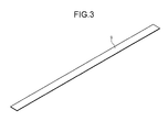
diffuser 9 is formed of a material containing polycarbonate resin or acrylic resin mixed with a diffusing material for diffusing light. As shown inFIG. 2 , thediffuser 9 is provided in a space formed by thelower surface cover 7 and theattachment member 2.FIG. 3 is a diagram of an external appearance example of thediffuser 9. As shown in an example inFIG. 2 , thediffuser 9 shown in an example inFIG. 3 is attached to thehollows 6a. That is, thediffuser 9 is a member provided between thelower surface cover 7 and the light-emittingelements 12 and configured to diffuse lights emitted from the light-emittingelements 12. Further, thediffuser 9 reflects a part of the lights emitted from the light-emittingelements 12. - The light-emitting
module 10 is provided in the space formed by thelower surface cover 7 and theattachment member 2.FIG. 4 is a diagram of an external appearance example of the light-emitting module. As shown inFIG. 4 , the light-emittingmodule 10 includes a plurality ofsubstrates 11 and the plurality of light-emittingelements 12 respectively mounted on the plurality ofsubstrates 11. Thesubstrates 11 are attached to theattachment member 2. Consequently, the light-emittingmodule 10 is attached to theattachment member 2. - The light-emitting
elements 12 are, for example, LEDs and emit lights. A part of the lights emitted by the light-emittingelements 12 are diffused by thediffuser 9, transmitted through thelower surface cover 7, and travel to the floor of the room. A part of the lights emitted by the light-emittingelements 12 is directly transmitted through the side surface covers 6 and theside surface sections 7a or reflected or diffused by thediffuser 9 and transmitted through the side surface covers 6 and theside surface sections 7a, refracted by theprisms 7b, and travels to the ceiling. Not all of the lights made incident on theprisms 7b travel to the ceiling. Some of the lights made incident on theprisms 7b travel to lateral directions. - The
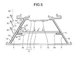
prisms 7b are explained.FIG. 5 is a sectional view of a portion covered with thelower surface cover 7 on the left side inFIG. 1 . Theprisms 7b included in the portion covered with thelower surface cover 7 on the left side inFIG. 1 are explained with reference toFIG. 5 . Theprisms 7b included in a portion covered with thelower surface cover 7 on the right side inFIG. 1 are the same as theprisms 7b shown inFIG. 5 . Therefore, explanation of theprisms 7b included in the portion covered with thelower surface cover 7 on the right side inFIG. 1 is omitted. - As shown in
FIG. 5 , when the luminaire 1 is attached to the ceiling, theprisms 7b adjust the traveling directions of the lights transmitted through the side surface covers 6 and theside surface sections 7a such thatlights 43 are irradiated on the ceiling in traveling directions at an angle of β with respect to adirection 90 perpendicular to the ceiling. β is, for example, a value equal to or larger than 40 degrees and equal to or smaller than 90 degrees. However, β is not limited to the value. As explained above, the lights transmitted through the side surface covers 6 and theside surface sections 7a are, for example, lights 40 directly made incident on the side surface covers 6 from the light-emittingelements 12,lights 41 diffused by thediffuser 9, andlights 42 reflected by thediffuser 9. - As shown in
FIG. 5 , in the luminaire 1 in this embodiment, the cross section of theprism 7b is substantially triangular. An angle α formed by adirection 7d indicated by one side of the substantial triangle indicated by the cross section of theprism 7b and adirection 9a perpendicular to the planar shape of thediffuser 9 may be any value as long as the lights from theprisms 7b can irradiate the ceiling. As shown inFIG. 5 , a refractive index of theprisms 7b with respect to the lights emitted from the light-emittingelements 12 is, for example, equal to or larger than 1.45 and equal to or smaller than 1.65. The luminaire 1 is designed such that the ceiling and thediffuser 9 are substantially parallel to each other when the luminaire 1 is attached to the ceiling. Therefore, when the luminaire 1 is attached to the ceiling, thedirection 90 and thedirection 9a are substantially parallel to each other. - In the luminaire 1 in this embodiment, the
diffuser 9 having transmittance for setting a ratio of an amount of the lights transmitted through thelower surface cover 7 and an amount of the lights adjusted by theprisms 7b and irradiated on the ceiling to a ratio in a range of 1:9 to 2:8 is used. In addition, in the luminaire 1 in this embodiment, thediffuser 9 is provided in a position where such a ratio is obtained. - An example of a positional relation between the
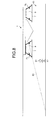
diffuser 9 and thelower surface cover 7 is explained.FIG. 6 is a diagram showing an example of the positional relation between thediffuser 9 and thelower surface cover 7.FIG. 6 is a sectional view of the luminaire 1. As indicated by an example shown inFIG. 6 , an angle ε formed by thestraight line 80, which connects thelower end 6b of theside surface cover 6 on which theprisms 7b are provided and thepoint 9b, and thedirection 9a perpendicular to the planar shape of thediffuser 9 is an angle equal to or larger than 5 degrees and equal to or smaller than 30 degrees. Thepoint 9b is a point on thediffuser 9 most distant from thelower end 6b on a cross section including thelower end 6b. That is, thepoint 9b is a point on thediffuser 9 most distant from thelower end 6b on a plane including thelower end 6b. - As explained above, the luminaire 1 according to the embodiment includes the light-emitting
elements 12, the side surface covers 6, thelower surface cover 7, thediffuser 9, and theprisms 7b, which are an example of optical members. The light-emittingelements 12 emit lights. The side surface covers 6 are arranged at the predetermined distance from the light-emittingelements 12. The light emitted by the light-emittingelement 12 is transmitted through theside surface cover 6. Thelower surface cover 7 is provided at the lower ends of the side surface covers 6. The light emitted by the light-emittingelement 12 is transmitted through thelower surface cover 7. Thediffuser 9 is a member provided between thelower surface cover 7 and the light-emittingelements 12 to diffuse the lights emitted by the light-emitting element. Theprisms 7b adjust traveling directions of the lights transmitted through the side surface covers 6 to be different from traveling directions of the lights emitted by the light-emittingelements 12 and transmitted through thelower surface cover 7. In this way, in the luminaire 1, thediffuser 9 is provided further on the upper side than thelower surface cover 7. Therefore, as shown inFIG. 7 , light from the luminaire 1 is not glaring for aperson 81 present in aposition 82 further on the outer side of the luminaire 1 than thedirection 80 in aroom 60. Therefore, with the luminaire 1 according to this embodiment, it is possible to suppress glare. With the luminaire 1 according to this embodiment, the lights transmitted through the side surface covers 6 travel in the directions different from the traveling directions of the lights emitted by the light-emittingelements 12 and transmitted through thelower surface cover 7. Therefore, with the luminaire 1 according to this embodiment, it is possible to improve a sense of brightness of a space and provide a comfortable lighting space for a person. Therefore, with the luminaire 1 according to this embodiment, it is possible to suppress glare and improve the sense of brightness. - In an example shown in
FIG. 7 , the lights travel in the lateral direction from theprisms 7b. Therefore, theperson 81 can view slight lights from theprisms 7b. Thereafter, when theperson 81 moves to a position 83 further on the luminaire 1 side than thedirection 80 as shown in FIG. 9, theperson 81 can view the lights diffused by thediffuser 9. However, theperson 81 already views the slight lights from theprisms 7b in theposition 82. Therefore, even when theperson 81 moves to the position 83, theperson 81 hardly has a sense of discomfort to the lights from thediffuser 9. Therefore, with the luminaire 1 according to this embodiment, it is possible to suppress a sense of discomfort to the lights from the luminaire 1. - In the luminaire 1 according to this embodiment, the angle ε formed by the
straight line 80, which connects thelower end 6b of theside surface cover 6 and thepoint 9b on thediffuser 9 most distant from thelower end 6b of theside surface cover 6, and thedirection 9a perpendicular to the planar shape of thediffuser 9 is an angle equal to or larger than 5 degrees and equal to or smaller than 30 degrees. - In the luminaire 1 according to this embodiment, the lights diffused or reflected by the
diffuser 9 are transmitted through theside surface cover 6. - The luminaire 1 according to this embodiment includes the
attachment member 2 for attaching the luminaire 1 to the ceiling. In the luminaire 1, theprisms 7b adjust the traveling directions of the lights transmitted through the side surface covers 6 such that the lights transmitted through the side surface covers 6 are irradiated on the ceiling. Therefore, with the luminaire 1 according to this embodiment, the lights are irradiated on the ceiling as well. Therefore, with the luminaire 1 according to this embodiment, it is possible to improve a sense of brightness of a space and provide a comfortable lighting space for a person. - In the luminaire 1 according to this embodiment, the
prisms 7b adjust the traveling directions of the lights transmitted through the side surface covers 6 such that the lights are irradiated on the ceiling in the traveling directions at an angle equal to or larger than 40 degrees and equal to or smaller than 90 degrees with respect to the direction perpendicular to the ceiling. - In the luminaire 1 according to this embodiment, the refractive index of the
prisms 7b is equal to or larger than 1.49 and equal to or smaller than 1.59. - In the luminaire 1 according to this embodiment, a ratio of an amount of the lights transmitted through the
lower surface cover 7 and an amount of the lights refracted by theprisms 7b and irradiated on the ceiling is in a range of 1:9 to 2:8. Therefore, with the luminaire 1, it is possible to appropriately set an amount of the lights in the floor surface direction and an amount of the lights in the ceiling direction. - In the luminaire 1 according to this embodiment, the
hollows 6a are formed in a part of the side surface covers 6. In the luminaire 1, protrusions on theprism 7b is configured to fit in the hollows by which theprisms 7b to be attached to the side surface covers 6. Therefore, with the luminaire 1, it is possible to easily attach theside surface cover 6 to theprism 7b. - In the luminaire 1 according to this embodiment, the
lower surface cover 7 and theprisms 7b are integrally molded. Consequently, thelower surface cover 7 and theprisms 7b can be provided as one component. Therefore, it is possible to reduce the number of components. - In the luminaire 1 according to this embodiment, the side surface covers 6 and the
prisms 7b may be integrally molded. Consequently, the side surface covers 6 and theprisms 7b can be provided as one component. Therefore, it is possible to reduce the number of components. - In the luminaire 1 according to this embodiment, the side surface covers 6, the
lower surface cover 7, and theprisms 7b may be integrally molded. Consequently, the side surface covers 6, thelower surface cover 7, and theprisms 7b can be provided as one component. Therefore, it is possible to reduce the number of components. - In the luminaire 1 according to this embodiment, the side surface covers 6, the
lower surface cover 7, theprisms 7b, and thediffuser 9 may be integrally molded. Consequently, the side surface covers 6, thelower surface cover 7, theprisms 7b, and thediffuser 9 can be provided as one component. Therefore, it is possible to reduce the number of components. - In the luminaire 1 according to this embodiment, the
prisms 7b are provided on the side surface covers 6 that is located on the outermost side among the plurality of side surface covers 6. Consequently, theprisms 7b are provided only on the side surface covers 6 present in positions where lights can be irradiated on the ceiling. Therefore, the number of theprisms 7b used for making the ceiling bright can be minimized. - In the luminaire 1 according to this embodiment, the
prisms 7b may be provided in each of the plurality of side surface covers 6. Consequently, for example, theprisms 7b are provided not only on the side surface covers 6 present in the positions where lights can be irradiated on the ceiling but also on the side surface covers 6 present in positions where lights can be irradiated on thereflector 3. Therefore, it is possible to increase an amount of lights reflected by thereflector 3. Therefore, it is possible to further improve a sense of brightness of a space and provide a more comfortable lighting space for a person. - In the luminaire 1 according to this embodiment, the
prisms 7b are formed of a material containing acrylic resin or polycarbonate resin. - The shapes, the materials, and the material properties of the members according to the embodiment are not limited to the examples explained and shown in the embodiment and the figures.
- As explained above, according to the embodiment, it is possible to suppress glare.
- While certain embodiments have been described, these embodiments have been presented by way of example only, and are not intended to limit the scope of the inventions. Indeed, the novel embodiments described herein may be embodied in a variety of other forms; furthermore, various omissions, substitutions, and changes in the form of the embodiments described herein may be made without departing from the spirit of the inventions. The accompanying claims and their equivalents are intended to cover such forms or modifications as would fall within the scope and spirit of the inventions.
Claims (15)
- A luminaire comprising:a light-emitting element (12) configured to emit light;a side surface cover (6) arranged a predetermined distance from the light-emitting element (12) and through which the light emitted by the light-emitting element (12) is transmitted;a lower surface cover (7) provided at a lower end of the side surface cover (6) and through which the light emitted by the light-emitting element (12) is transmitted;a diffuser (9) provided between the lower surface cover (7) and the light-emitting element (12) to diffuse the light emitted by the light-emitting element; andan optical member (7b) configured to adjust a traveling direction of the light transmitted through the side surface cover (6) to be different from a traveling direction of the light emitted by the light-emitting element (12) and transmitted through the lower surface cover (7).
- The luminaire according to claim 1, wherein an angle formed by a straight line, which connects a lower end the side surface cover (6) and a point on the diffuser (9) most distant from the lower end of the side surface cover (6), and a direction perpendicular to a planar shape of the diffuser (9) is an angle equal to or larger than 5 degrees and equal to or smaller than 30 degrees.
- The luminaire according to claim 1 or 2, wherein the light diffused or reflected by the diffuser (9) is transmitted through the side surface cover (6).
- The luminaire according to claim 3, further comprising an attachment member (2) for attaching the luminaire to a ceiling, wherein
the optical member (7b) adjusts the traveling direction of the light transmitted through the side surface cover (6) such that the light transmitted through the side surface cover (6) is irradiated on the ceiling. - The luminaire according to claim 4, wherein the optical member (7b) adjusts the traveling direction of the light transmitted through the side surface cover (6) such that the light is irradiated on the ceiling in a traveling direction at an angle equal to or larger than 40 degrees and equal to or smaller than 90 degrees with respect to a direction perpendicular to the ceiling.
- The luminaire according to any one of claims 1 to 5, wherein a refractive index of the optical member (7b) is equal to or larger than 1.45 and equal to or smaller than 1.65.
- The luminaire according to any one of claims 1 to 6, wherein a ratio of an amount of the light transmitted through the lower surface cover (7) and an amount of the light adjusted by the optical member (7b) is in a range of 1:9 to 2:8.
- The luminaire according to any one of claims 1 to 7, wherein
a hollow is formed in a part of the side surface cover (6), and
a protrusion on the optical member configured to fit in the hollow by which the optical member (7b) to be attached to the side surface cover (6). - The luminaire according to any one of claims 1 to 8, wherein the lower surface cover (7) and the optical member (7b) are integrally molded.
- The luminaire according to any one of claims 1 to 7, wherein the side surface cover (6) and the optical member (7b) are integrally molded.
- The luminaire according to any one of claims 1 to 7, wherein the side surface cover (6), the lower surface cover (7), and the optical member (7b) are integrally molded.
- The luminaire according to any one of claims 1 to 7, wherein
the lower surface cover (7) includes a side surface section (7a) configured to cover the side surface cover (6), and
the lower surface cover (7), the side surface section (7a), the optical member (7b), the side surface cover (6), and the diffuser (9) are integrally molded. - The luminaire according to any one of claims 1 to 12, wherein
the luminaire includes a plurality of the side surface covers (6), and
the optical member (7b) is provided on the side surface cover (6) that is located on an outermost side among the plurality of side surface covers (6). - The luminaire according to any one of claims 1 to 12, wherein
the luminaire includes a plurality of the side surface covers (6), and
the optical member (7b) is provided in each of the plurality of side surface covers (6). - The luminaire according to any one of claims 1 to 14, wherein the optical member (7b) is formed of a material containing acrylic resin or polycarbonate resin.
Applications Claiming Priority (1)
| Application Number | Priority Date | Filing Date | Title |
|---|---|---|---|
| JP2012208696A JP2014063665A (en) | 2012-09-21 | 2012-09-21 | Illumination apparatus |
Publications (2)
| Publication Number | Publication Date |
|---|---|
| EP2711614A2 true EP2711614A2 (en) | 2014-03-26 |
| EP2711614A3 EP2711614A3 (en) | 2014-05-07 |
Family
ID=48747354
Family Applications (1)
| Application Number | Title | Priority Date | Filing Date |
|---|---|---|---|
| EP13173641.5A Withdrawn EP2711614A3 (en) | 2012-09-21 | 2013-06-25 | Luminaire |
Country Status (4)
| Country | Link |
|---|---|
| US (1) | US20140085874A1 (en) |
| EP (1) | EP2711614A3 (en) |
| JP (1) | JP2014063665A (en) |
| CN (1) | CN203082694U (en) |
Cited By (1)
| Publication number | Priority date | Publication date | Assignee | Title |
|---|---|---|---|---|
| WO2022234143A1 (en) * | 2021-05-07 | 2022-11-10 | Schreder S.A. | Modular lighting apparatus with cooling channel |
Families Citing this family (2)
| Publication number | Priority date | Publication date | Assignee | Title |
|---|---|---|---|---|
| KR101906893B1 (en) * | 2012-04-27 | 2018-10-11 | 삼성전자주식회사 | Light emitting device |
| CN109539186A (en) * | 2018-12-29 | 2019-03-29 | 深圳市晨北科技有限公司 | Backing structure |
Family Cites Families (6)
| Publication number | Priority date | Publication date | Assignee | Title |
|---|---|---|---|---|
| GB718650A (en) * | 1952-06-20 | 1954-11-17 | Seidenberg Freres | Improvements in or relating to light diffusers for tubular lamps |
| GB843627A (en) * | 1956-04-19 | 1960-08-04 | British Thomson Houston Co Ltd | Improvements in and relating to electric fluorescent lighting units |
| US3159352A (en) * | 1960-11-16 | 1964-12-01 | Wakefield Corp | Luminaire |
| US4891737A (en) * | 1988-12-09 | 1990-01-02 | Thin-Lite Corporation | Quick fit diffuser lens apparatus |
| JP4437024B2 (en) * | 2003-10-01 | 2010-03-24 | 日本ライツ株式会社 | Flat lighting device |
| DE502005011073D1 (en) * | 2005-01-10 | 2011-04-21 | Siteco Beleuchtungstech Gmbh | Luminaire with hollow fiber optic cable |
-
2012
- 2012-09-21 JP JP2012208696A patent/JP2014063665A/en active Pending
-
2013
- 2013-01-09 CN CN2013200116511U patent/CN203082694U/en not_active Expired - Fee Related
- 2013-06-19 US US13/921,638 patent/US20140085874A1/en not_active Abandoned
- 2013-06-25 EP EP13173641.5A patent/EP2711614A3/en not_active Withdrawn
Non-Patent Citations (1)
| Title |
|---|
| None |
Cited By (2)
| Publication number | Priority date | Publication date | Assignee | Title |
|---|---|---|---|---|
| WO2022234143A1 (en) * | 2021-05-07 | 2022-11-10 | Schreder S.A. | Modular lighting apparatus with cooling channel |
| NL2028173B1 (en) * | 2021-05-07 | 2022-11-24 | Schreder Sa | Modular lighting apparatus with cooling channel |
Also Published As
| Publication number | Publication date |
|---|---|
| EP2711614A3 (en) | 2014-05-07 |
| JP2014063665A (en) | 2014-04-10 |
| CN203082694U (en) | 2013-07-24 |
| US20140085874A1 (en) | 2014-03-27 |
Similar Documents
| Publication | Publication Date | Title |
|---|---|---|
| US9279550B2 (en) | Luminaires having batwing photometric distribution | |
| JP6868016B2 (en) | Lighting system and how to generate light output | |
| US9632295B2 (en) | Flood optic | |
| KR20140097121A (en) | Lighting Device | |
| CN205619003U (en) | Light source device and ligthing paraphernalia | |
| US9671087B2 (en) | Illumination device | |
| CN106062465A (en) | Light source apparatus and lighting apparatus | |
| US9377180B2 (en) | Luminous flux control member, light emission device, and illumination device | |
| EP2711614A2 (en) | Luminaire | |
| US20150345735A1 (en) | Secondary optical element and light source module | |
| TWI500884B (en) | Lighting device and cove lighting module using the same | |
| JP7012244B2 (en) | Lenses, luminaires, luminaires | |
| KR101696367B1 (en) | Diffusion Lens for LED lighting | |
| CN106062471B (en) | Ligthing paraphernalia, light source cover, light control member and light source unit | |
| US8746919B2 (en) | Luminaire controlling a luminous intensity distribution | |
| CN104566212B (en) | lens | |
| JP2015162447A (en) | Lighting equipment and light source cover | |
| WO2017092604A1 (en) | Led lamp | |
| KR101682676B1 (en) | Diffusion Lens having Scaterring Function for LED lighting | |
| KR101713973B1 (en) | Diffuser for led illuminator | |
| CN206329925U (en) | Light source assembly and ligthing paraphernalia | |
| JP2014142998A (en) | Optical element and lighting apparatus | |
| CN212510847U (en) | Desktop lighting device | |
| KR101272690B1 (en) | Lighting module | |
| WO2016181789A1 (en) | Light beam control member, light-emitting device, and illumination device |
Legal Events
| Date | Code | Title | Description |
|---|---|---|---|
| PUAI | Public reference made under article 153(3) epc to a published international application that has entered the european phase |
Free format text: ORIGINAL CODE: 0009012 |
|
| AK | Designated contracting states |
Kind code of ref document: A2 Designated state(s): AL AT BE BG CH CY CZ DE DK EE ES FI FR GB GR HR HU IE IS IT LI LT LU LV MC MK MT NL NO PL PT RO RS SE SI SK SM TR |
|
| AX | Request for extension of the european patent |
Extension state: BA ME |
|
| PUAL | Search report despatched |
Free format text: ORIGINAL CODE: 0009013 |
|
| AK | Designated contracting states |
Kind code of ref document: A3 Designated state(s): AL AT BE BG CH CY CZ DE DK EE ES FI FR GB GR HR HU IE IS IT LI LT LU LV MC MK MT NL NO PL PT RO RS SE SI SK SM TR |
|
| AX | Request for extension of the european patent |
Extension state: BA ME |
|
| RIC1 | Information provided on ipc code assigned before grant |
Ipc: F21V 3/00 20060101AFI20140328BHEP Ipc: F21S 8/04 20060101ALI20140328BHEP Ipc: F21V 3/04 20060101ALI20140328BHEP Ipc: F21V 13/02 20060101ALI20140328BHEP Ipc: F21Y 103/00 20060101ALN20140328BHEP Ipc: F21S 4/00 20060101ALI20140328BHEP Ipc: F21Y 101/02 20060101ALN20140328BHEP |
|
| STAA | Information on the status of an ep patent application or granted ep patent |
Free format text: STATUS: THE APPLICATION IS DEEMED TO BE WITHDRAWN |
|
| 18D | Application deemed to be withdrawn |
Effective date: 20141108 |