EP2711575B1 - Rotation transmitting apparatus, vehicle steering system, and intermediate shaft - Google Patents
Rotation transmitting apparatus, vehicle steering system, and intermediate shaft Download PDFInfo
- Publication number
- EP2711575B1 EP2711575B1 EP13184681.8A EP13184681A EP2711575B1 EP 2711575 B1 EP2711575 B1 EP 2711575B1 EP 13184681 A EP13184681 A EP 13184681A EP 2711575 B1 EP2711575 B1 EP 2711575B1
- Authority
- EP
- European Patent Office
- Prior art keywords
- shaft
- tooth
- rotary shaft
- protrusion
- external
- Prior art date
- Legal status (The legal status is an assumption and is not a legal conclusion. Google has not performed a legal analysis and makes no representation as to the accuracy of the status listed.)
- Not-in-force
Links
Images


Classifications
-
- F—MECHANICAL ENGINEERING; LIGHTING; HEATING; WEAPONS; BLASTING
- F16—ENGINEERING ELEMENTS AND UNITS; GENERAL MEASURES FOR PRODUCING AND MAINTAINING EFFECTIVE FUNCTIONING OF MACHINES OR INSTALLATIONS; THERMAL INSULATION IN GENERAL
- F16D—COUPLINGS FOR TRANSMITTING ROTATION; CLUTCHES; BRAKES
- F16D1/00—Couplings for rigidly connecting two coaxial shafts or other movable machine elements
- F16D1/10—Quick-acting couplings in which the parts are connected by simply bringing them together axially
- F16D1/108—Quick-acting couplings in which the parts are connected by simply bringing them together axially having retaining means rotating with the coupling and acting by interengaging parts, i.e. positive coupling
-
- F—MECHANICAL ENGINEERING; LIGHTING; HEATING; WEAPONS; BLASTING
- F16—ENGINEERING ELEMENTS AND UNITS; GENERAL MEASURES FOR PRODUCING AND MAINTAINING EFFECTIVE FUNCTIONING OF MACHINES OR INSTALLATIONS; THERMAL INSULATION IN GENERAL
- F16D—COUPLINGS FOR TRANSMITTING ROTATION; CLUTCHES; BRAKES
- F16D3/00—Yielding couplings, i.e. with means permitting movement between the connected parts during the drive
- F16D3/02—Yielding couplings, i.e. with means permitting movement between the connected parts during the drive adapted to specific functions
- F16D3/06—Yielding couplings, i.e. with means permitting movement between the connected parts during the drive adapted to specific functions specially adapted to allow axial displacement
-
- B—PERFORMING OPERATIONS; TRANSPORTING
- B62—LAND VEHICLES FOR TRAVELLING OTHERWISE THAN ON RAILS
- B62D—MOTOR VEHICLES; TRAILERS
- B62D1/00—Steering controls, i.e. means for initiating a change of direction of the vehicle
- B62D1/02—Steering controls, i.e. means for initiating a change of direction of the vehicle vehicle-mounted
- B62D1/16—Steering columns
- B62D1/18—Steering columns yieldable or adjustable, e.g. tiltable
- B62D1/185—Steering columns yieldable or adjustable, e.g. tiltable adjustable by axial displacement, e.g. telescopically
-
- F—MECHANICAL ENGINEERING; LIGHTING; HEATING; WEAPONS; BLASTING
- F16—ENGINEERING ELEMENTS AND UNITS; GENERAL MEASURES FOR PRODUCING AND MAINTAINING EFFECTIVE FUNCTIONING OF MACHINES OR INSTALLATIONS; THERMAL INSULATION IN GENERAL
- F16C—SHAFTS; FLEXIBLE SHAFTS; ELEMENTS OR CRANKSHAFT MECHANISMS; ROTARY BODIES OTHER THAN GEARING ELEMENTS; BEARINGS
- F16C3/00—Shafts; Axles; Cranks; Eccentrics
- F16C3/02—Shafts; Axles
- F16C3/03—Shafts; Axles telescopic
- F16C3/035—Shafts; Axles telescopic with built-in bearings
-
- F—MECHANICAL ENGINEERING; LIGHTING; HEATING; WEAPONS; BLASTING
- F16—ENGINEERING ELEMENTS AND UNITS; GENERAL MEASURES FOR PRODUCING AND MAINTAINING EFFECTIVE FUNCTIONING OF MACHINES OR INSTALLATIONS; THERMAL INSULATION IN GENERAL
- F16C—SHAFTS; FLEXIBLE SHAFTS; ELEMENTS OR CRANKSHAFT MECHANISMS; ROTARY BODIES OTHER THAN GEARING ELEMENTS; BEARINGS
- F16C2326/00—Articles relating to transporting
- F16C2326/20—Land vehicles
- F16C2326/24—Steering systems, e.g. steering rods or columns
-
- F—MECHANICAL ENGINEERING; LIGHTING; HEATING; WEAPONS; BLASTING
- F16—ENGINEERING ELEMENTS AND UNITS; GENERAL MEASURES FOR PRODUCING AND MAINTAINING EFFECTIVE FUNCTIONING OF MACHINES OR INSTALLATIONS; THERMAL INSULATION IN GENERAL
- F16D—COUPLINGS FOR TRANSMITTING ROTATION; CLUTCHES; BRAKES
- F16D1/00—Couplings for rigidly connecting two coaxial shafts or other movable machine elements
- F16D1/10—Quick-acting couplings in which the parts are connected by simply bringing them together axially
- F16D2001/103—Quick-acting couplings in which the parts are connected by simply bringing them together axially the torque is transmitted via splined connections
-
- Y—GENERAL TAGGING OF NEW TECHNOLOGICAL DEVELOPMENTS; GENERAL TAGGING OF CROSS-SECTIONAL TECHNOLOGIES SPANNING OVER SEVERAL SECTIONS OF THE IPC; TECHNICAL SUBJECTS COVERED BY FORMER USPC CROSS-REFERENCE ART COLLECTIONS [XRACs] AND DIGESTS
- Y10—TECHNICAL SUBJECTS COVERED BY FORMER USPC
- Y10T—TECHNICAL SUBJECTS COVERED BY FORMER US CLASSIFICATION
- Y10T403/00—Joints and connections
- Y10T403/70—Interfitted members
- Y10T403/7026—Longitudinally splined or fluted rod
- Y10T403/7035—Specific angle or shape of rib, key, groove, or shoulder
Definitions
- the invention relates to a rotation transmitting apparatus having two rotary shafts that are fitted together so as to be slidable relative to each other in the axial direction and so as to be engageable with each other in the rotational direction, a vehicle steering system, and an intermediate shaft.
- JP 2009-168144 A describes a rotation transmitting apparatus in which a spline shaft is fitted to a spline sleeve so as to be slidable relative to the spline sleeve in the axial direction and so as to be engageable with the spline sleeve in the rotational direction.
- JP 2009-168144 A describes a driving force transmission apparatus having protrusions 6PR formed at radially outer ends of ridges so as to extend in the axial direction, and protrusions 6RB formed at axially opposite ends of the ridges so as to extend continuously in the circumferential direction.
- the protrusions 6PR and the protrusions 6RB have the effect of decreasing a radial backlash between the spline sleeve and the spline shaft, thereby allowing the spline shaft to smoothly slide relative to the spline sleeve.
- the protrusions 6PR have the function of decreasing the radial backlash, but do not have the function of absorbing a backlash in the rotational direction. Therefore, it is not possible to smoothly transmit the rotation of the spline sleeve to the spline shaft. Further, the protrusions 6RB do not have the function of absorbing the backlash in the rotational direction. Therefore, it is not possible to smoothly transmit the rotation of the spline shaft to the spline sleeve.
- a rotation transmitting apparatus having the features of the preamble of claim 1 is known for example from WO 2012/066904 A1
- the invention provides a rotation transmitting apparatus configured such that rotation is smoothly transmitted between a first rotary shaft and a second rotary shaft, a vehicle steering system including the rotation transmitting apparatus, and an intermediate shaft provided with the rotation transmitting apparatus.
- a rotation transmitting apparatus including a first rotary shaft on which multiple external teeth projected radially outward and extending in an axial direction are formed so as to be arranged in a circumferential direction, and a second rotary shaft in which multiple internal teeth projected radially inward and extending in the axial direction are formed so as to be arranged in the circumferential direction, the second rotary shaft being fitted to the first rotary shaft so as to be slidable relative to the first rotary shaft in the axial direction and so as to be engageable with the first rotary shaft in a rotational direction through the use of the external teeth and the internal teeth, in which: the external teeth and the internal teeth have tooth flanks that are engaged with each other in the rotational direction; a protrusion is formed on the tooth flank of one of the external tooth and the internal tooth, the protrusion being projected toward the corresponding tooth flank of the other of the external tooth and the internal tooth and extending in the axial direction; and the protrusion is made
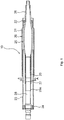
- FIG. 1 is a longitudinal sectional view of the vehicle steering system 10.
- FIG. 2 is a sectional view taken along the line A-A in FIG. 1 .
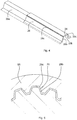
- FIG. 3 is a partially enlarged sectional view of FIG. 2 .
- FIG. 4 is an enlarged perspective view illustrating part of an inner shaft.
- FIG. 5 is a sectional view for describing a shaping process performed with the use of dies.
- the vehicle steering system 10 includes a steering tube 20 and a steering shaft 25 that are rotatably supported by the steering tube 20 via bearings 22, 24.
- the vehicle steering system 10 is secured to a vehicle body via a bracket (not shown).
- a steering wheel (not shown) is rotatably coupled to one end of the steering shaft 25, and an intermediate shaft (not shown) is rotatably coupled to the other end of the steering shaft 25.
- the steering tube 20 is formed of a cylindrical outer tube 21 and a cylindrical inner tube 23.
- the inner tube 23 is fitted to the outer tube 21 with a clearance.
- the bracket (not shown) is secured to the outer tube 21, and an outer shaft 26, which will be described later, is rotatably supported by the outer tube 21 via the bearing 22.
- the steering shaft 25 is formed of the cylindrical outer shaft 26 and the columnar inner shaft 28.
- the inner shaft 28 is fitted to the outer shaft 26 so as to be slidable relative to the outer shaft 26 in the axial direction and so as to be engageable with the outer shaft 26 in the rotational direction.
- the steering wheel (not shown) is coupled to one end of the outer shaft 26, and the intermediate shaft (not shown) is coupled to an end of the inner shaft 28, which is on the opposite side of the inner shaft 28 from the outer shaft 26. Further, the intermediate shaft is coupled to wheels via a pinion shaft and a rack shaft, which are not shown.
- splines are formed on the inner periphery of the outer shaft 26 and the outer periphery of the inner shaft 28.
- the splines of the outer shaft 26 have internal teeth 27 projected radially inward and each having a trapezoidal sectional shape
- the splines of the inner shaft 28 have external teeth 29 projected radially outward and each having a trapezoidal sectional shape.
- the internal teeth 27 are formed on the inner periphery of the outer shaft 26 at equal intervals in the circumferential direction, and extend in the axial direction.
- the external teeth 29 are formed on the outer periphery of the inner shaft 28 at equal intervals in the circumferential direction, and extend in the axial direction.
- the internal teeth 27 and the external teeth 29 have tooth flanks that are engaged with each other in the rotational direction.
- the section of the tooth flank of each of the internal teeth 27 has a straight line
- the section of the tooth flank of each of the external teeth 29 has an involute curve.
- the external teeth 29 are manufactured by forming base external teeth 29a each having a trapezoidal sectional shape through, for example, form rolling of ferrous material, then forming a resin coating 29b having a predetermined thickness on the base external teeth 29a, and finally shaping the outer periphery of the resin coating 29b with the use of, for example, dies ( FIG. 5 ).
- a protrusion 29c having a semicircular sectional shape is formed on each of the right and left tooth flanks of the external tooth 29.
- the protrusion 29c is projected to such a position as to contact the corresponding tooth flank of the internal tooth 27, and extends in parallel with the axis of the inner shaft 28.
- a portion of each spline of the inner shaft 28, the portion extending from one end of the spline to an intermediate portion thereof, is formed of the external tooth 29 having the resin coating 29b, and the remaining portion of the spline, the remaining portion extending from the intermediate portion to the other end of the spline, is formed of a portion of the base external tooth 29a having no resin coating 29b. It is not necessary to form the protrusions 29c on all the external teeth 29.
- no protrusions 29c are formed on the external teeth 29 that are adjacent to the external tooth 29 on which the protrusions 29c are formed.
- the area of contact between the protrusions 29c and the tooth flanks of the internal teeth 27 is smaller than the area of contact between the tooth flanks of the internal teeth 27 and the tooth flanks of the external teeth 29. Therefore, the protrusions 29c are easily deformed elastically.
- the base external teeth 29a each having a trapezoidal sectional shape are formed on the outer periphery of the inner shaft 28 at equal intervals in the circumferential direction.
- the resin coating 29b is formed on the portion of each base external tooth 29a, which extends from the one end of the base external tooth 29a to the intermediate portion thereof. After the resin coating 29b is cured, the resin coating 29b is subjected to the shaping process performed with the use of dies 95.
- the dies 95 include a rough cutting die and a finishing die.
- the resin coating 29b is roughly cut by the rough cutting die, and then the resin coating 29b is cut by the finishing die so as to be finished.
- the tooth flanks and the protrusions 29c are simultaneously formed.
- the portion of each spline of the inner shaft 28, which extends from one end of the spline to the intermediate portion thereof, is formed of the external tooth 29, and the remaining portion of the spline is formed of the base external teeth 29a.
- the resin coating 29b is made of a hot-melt resin. In another example, a two-component curable resin may be used.
- the inner shaft 28 is spline-fitted to the outer shaft 26. Because the protrusions 29c are softer than the tooth flanks, the inner shaft 28 is smoothly fitted to the outer shaft 26 and slid in the axial direction with no radial backlash.
- the bearing 22 is fitted to the outer tube 21, and the bearing 22 is secured to the outer tube 21 by clinching part of the outer tube 21.
- the bearing 24 is fitted to the inner tube 23, and the bearing 24 is secured to the inner tube 23 by clinching part of the inner tube 23.
- the bearing 22 is fitted to the steering shaft 25 and a snap ring is fitted to the steering shaft 25 to prevent the bearing 22 from being removed from the steering shaft 25.
- the bearing 24 is fitted to the steering shaft 25 and a snap ring is fitted to the steering shaft 25 to prevent the bearing 24 from being removed from the steering shaft 25.
- the steering shaft 25 is rotatably assembled to the steering tube 20.
- the outer tube 21 is moved in the longitudinal direction relative to the inner tube 23, and, at the same time, the outer shaft 26 is moved in the longitudinal direction relative to the inner shaft 28.
- the outer shaft 26 is smoothly slid relative to the inner shaft 28. Because the protrusions 29c extend over a predetermined length so as to be in parallel with the axis of the inner shaft 28, it is possible to restrain the outer shaft 26 from being tilted with respect to the inner shaft 28, and accordingly, the inner shaft 28 and the outer shaft 26 are easily assembled together.
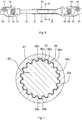
- FIG. 6 is a front view illustrating the intermediate shaft.
- FIG. 7 is a sectional view taken along the line B-B in FIG. 6 .
- FIG. 8 is a partially enlarged sectional view of FIG. 7 .
- the intermediate shaft 50 is formed of an upper shaft 51, a lower shaft 55 that is telescopically and rotatably coupled to the upper shaft 51, a first universal joint 60 provided at an end of the upper shaft 51, which is on the opposite side of the upper shaft 51 from the lower shaft 55.
- the first universal joint 60 is formed of a first yoke 61, a first cruciform member (not shown), and a second yoke 65.
- the first yoke 61 and the first cruciform member are coupled to each other so as to be rotatable relative to each other, and the first cruciform member and the second yoke 65 are coupled to each other so as to be rotatable relative to each other.
- the axis of rotation of the first yoke 61 with respect to the first cruciform member is orthogonal to the axis of rotation of the second yoke 65 with respect to the first cruciform member.
- a steering shaft 80 of a vehicle steering system is coupled to the first yoke 61, and the upper shaft 51 is formed integrally with the second yoke 65.
- a threaded hole 62 is formed in the first yoke 61. The threaded hole 62 is used to fixedly fasten the steering shaft 80 to the first yoke 61.
- the second universal joint 70 is formed of a third yoke 71, a second cruciform member (not shown), and a fourth yoke 75.
- the third yoke 71 and the second cruciform member are coupled to each other so as to be rotatable relative to each other, and the second cruciform member and the fourth yoke 75 are coupled to each other so as to be rotatable relative to each other.
- the axis of rotation of the third yoke 71 with respect to the second cruciform member is orthogonal to the axis of rotation of the fourth yoke 75 with respect to the second cruciform member.
- a pinion shaft 85 is coupled to the third yoke 71, and the lower shaft 55 is formed integrally with the fourth yoke 75.
- a threaded hole 72 is formed in the third yoke 71. The threaded hole 72 is used fixedly fasten the pinion shaft 85 to the third yoke 71.
- splines are formed on the inner periphery of the upper shaft 51 and on the outer periphery of the lower shaft 55.
- the splines of the upper shaft 51 have internal teeth 52 projected radially inward and each having a trapezoidal sectional shape.
- the splines of the lower shaft 55 have external teeth 56 projected radially outward and each having a trapezoidal sectional shape.
- the internal teeth 52 are formed on the inner periphery of the upper shaft 51 at equal intervals in the circumferential direction, and extend in the axial direction.
- the external teeth 56 are formed on the outer periphery of the lower shaft 55 at equal intervals in the circumferential direction, and extend in the axial direction.
- the internal teeth 52 and the external teeth 56 have tooth flanks that are engaged with each other.
- the section of the tooth flank of each of the internal teeth 52 has an involute curve
- the section of the tooth flank of each of the external teeth 56 has an involute curve.
- the external teeth 56 are manufactured by forming base external teeth 56a each having a trapezoidal sectional shape from ferrous material, then forming a resin coating 56b having a predetermined thickness on the base external teeth 56a, and finally shaping the outer periphery of the resin coating 56b with the use of, for example, dies.
- a protrusion 56c having a semicircular sectional shape is formed on each of the right and left tooth flanks of each external tooth 56.
- the protrusion 56c is projected to such a position that a clearance 56d is formed between the protrusion 56c and the tooth flank of the internal tooth 52, and extends in parallel with the axis of the lower shaft 55. It is not necessary to form the protrusions 56c on all the external teeth 56. In the embodiment described above, no protrusions 56c are formed on the external teeth 56 that are adjacent to the external tooth 56 on which the protrusions 56c are formed.
- the rotation of the steering shaft 80 is transmitted to the pinion shaft 85 via the first universal joint 60, the upper shaft 51, the lower shaft 55, and the second universal joint 70. Because the protrusions 56c of the external teeth 56 of the lower shaft 55 come into contact with the tooth flanks of the internal teeth 52 of the upper shaft 51, the protrusions 56c extend over a predetermined length so as to be in parallel with the axis of the lower shaft 55, and the protrusions 56c have an elastic force large enough to transmit torque, the rotation of the upper shaft 51 is smoothly transmitted to the lower shaft 55.
- the clearance 56d is made as small as possible because the protrusions 56c have elasticity that is lower than the elasticity of the tooth flanks of the external teeth 56. Therefore, the rotation of the upper shaft 51 is immediately transmitted to the lower shaft 55.
- the positions and the configuration of protrusions are made different from those in the vehicle steering system in the first embodiment so that the amount of elastic deformation of the protrusions is controlled. Because the components and the parts other than the protrusions are substantially the same as those in the first embodiment, like reference numerals are used to denote these components and the parts, and descriptions thereof are omitted.
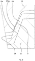
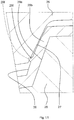
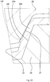
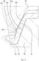
- FIG. 10 is a partially enlarged sectional view corresponding to FIG. 3 , and illustrating, as a state diagram, the amount of relative rotation between the outer shaft and the inner shaft.
- FIG. 11 is a partially enlarged view of FIG. 10 illustrating, as a state diagram, the amount of elastic deformation of the protrusion before the relative rotation.
- FIG. 12 is a partially enlarged view of FIG. 10 illustrating, as a state diagram, the amount of elastic deformation of the protrusion after the relative rotation.
- FIG.13 is a partially enlarged view of FIG. 10 illustrating, as a state diagram, the amount of elastic deformation of the protrusion during the relative rotation.
- a protrusion 29f having a trapezoidal sectional shape is formed on each of the right and left tooth flanks of each external tooth 29.
- the protrusion 29f is projected to such a position as to contact the corresponding tooth flank of the internal tooth 27, and extends in parallel with the axis of the inner shaft 28.
- Each protrusion 29f is formed at a position that is in an intermediate region in the tooth depth direction of the external tooth 29 and that is close to the tooth tip of the internal tooth 27. It is not necessary to form the protrusions 29f on all the external teeth 29. In the embodiment described above, no protrusions 29f are formed on the external teeth 29 that are adjacent to the external tooth 29 on which the protrusions 29f are formed.
- Each of the protrusions 29f has a trapezoidal sectional shape having a high height as indicated by a dashed line shown in FIG. 11 , before the inner shaft 28 is spline-fitted to the outer shaft 26.
- the protrusion 29f has a trapezoidal sectional shape that is bulged like a barrel and that has a lower height and a wider crest, as indicated by a continuous line shown in FIG. 11 , after the inner shaft 28 is spline-fitted to the outer shaft 26. In this state, if the outer shaft 26 is removed from the inner shaft 28, the protrusion 29f substantially restores its original trapezoidal shape having a high height, as indicated by the dashed line.
- the external teeth 29 of the inner shaft 28 are rotated clockwise and counterclockwise relative to the internal teeth 27 of the outer shaft 26 until the protrusions 29f reach positions indicated by two-dot chain lines shown in FIG. 10 and FIG. 13 .
- the trapezoidal shape having a high height indicated by the dashed line shown in FIG. 13 is shifted to a position indicated by a dotted line due to the relative rotation.
- the protrusions 29f are compressed more greatly because the protrusions 29f are compressed due to not only the spline-fitting but also the relative rotation.
- each protrusion 29f is brought into a trapezoidal sectional shape having a low height and a wide crest as indicated by the dashed line shown in FIG. 12 . That is, each protrusion 29f is plastically deformed into the trapezoidal sectional shape having a low height and a wide crest as indicated by the dashed line shown in FIG. 12 , from the trapezoidal sectional shape having a high height as indicated by the dashed line shown in FIG. 11 .
- the sectional shape of the protrusion 29f is brought into a trapezoidal shape that is bulged like a barrel and that has a lower height and a wider crest as indicated by the continuous line shown in FIG. 12 . Because the elastic force of the protrusion 29f having a small elastic deformation amount and having a large elastic modulus as shown in FIG. 12 , is smaller than the elastic force of the protrusion 29f having a large elastic deformation amount and having a small elastic modulus as shown in FIG.
- the outer shaft 26 is smoothly slid with a small sliding resistance, relative to the inner shaft 28. Because the method of forming the splines of the inner shaft 28 in the fourth embodiment is the same as that in the first embodiment, the description thereof is omitted.
- the inner shaft 28 is spline-fitted to the outer shaft 26.
- the protrusion 29f is elastically deformed from the trapezoidal shape having a high height as indicated by the dashed line shown in FIG. 11 , into the trapezoidal shape that has a lower height and a wider crest and that is bulged like a barrel, as indicated by the continuous line shown in FIG. 11 .
- the external teeth 29 of the inner shaft 28 are rotated clockwise and counterclockwise relative to the internal teeth 27 of the outer shaft 26 until the protrusions 29f reach the positions indicated by two-dot chain lines shown in FIG. 10 and FIG. 13 .
- the protrusion 29f is plastically deformed from the trapezoidal shape having a high height indicated by the dashed line shown in FIG. 13 , into the trapezoidal shape having a low height and a wide crest indicated by the dashed line in FIG. 12 . Due to the spline-fitting, each protrusion 29f is elastically deformed from the trapezoidal shape having a low height and a wide crest as indicated by the dashed line in FIG. 12 , into the trapezoidal shape having a lower height and a wider crest and bulged like a barrel as indicated by the continuous line shown in FIG. 12 .
- the elastic deformation amount of the protrusion 29f shown in FIG. 12 after the plastic deformation is smaller than the elastic deformation amount of the protrusion 29f shown in FIG. 11 before the plastic deformation. Therefore, the elastic force of the protrusion 29f shown in FIG. 12 after the plastic deformation is smaller than the elastic force of the protrusion 29f shown in FIG. 11 before the plastic deformation. As a result, by the protrusions 29f after the plastic deformation, the rotation of the outer shaft 26 is smoothly transmitted to the inner shaft 28 with no radial backlash. Thus, the outer shaft 26 is allowed to slide relative to the inner shaft 28 even under low load.
- the bearing 22 is secured to the outer tube 21 by fitting the bearing 22 to the outer tube 21 and clinching part of the outer tube 21.
- the bearing 24 is secured to the inner tube 23 by fitting the bearing 24 to the inner tube 23 and clinching part of the inner tube 23.
- the bearing 22 is fitted to the steering shaft 25, and the snap ring is fitted to the steering shaft 25 to prevent the bearing 22 from being removed from the steering shaft 25.
- the bearing 24 is fitted to the steering shaft 25, and the snap ring is fitted to the steering shaft 25 to prevent the bearing 24 from being removed from the steering shaft 25.
- the steering shaft 25 is rotatably assembled within the steering tube 20.
- the outer tube 21 is moved relative to the inner tube 23 in the longitudinal direction, and, at the same time, the outer shaft 26 is moved relative to the inner shaft 28 in the longitudinal direction.
- the outer shaft 26 is smoothly slid relative to the inner shaft 28 under low load. Because the protrusions 29f extend over a predetermined length so as to be in parallel with the axis of the inner shaft 28, it is possible restrain the outer shaft 26 from being tilted with respect to the inner shaft 28. Therefore, the inner shaft 28 and the outer shaft 26 are easily assembled together.
- the operation for rotating the steering wheel will be described.
- the rotation of the steering wheel is transmitted to the intermediate shaft via the outer shaft 26 and the inner shaft 28.
- the protrusions 29f of the external teeth 29 of the inner shaft 28 come into contact with the tooth flanks of the internal teeth 27 of the outer shaft 26, the protrusions 29f extend over a predetermined length so as to be in parallel with the axis of the inner shaft 28, the protrusions 29f have an elastic force large enough to transmit torque, and the elastic force of the protrusions 29f is reduced by the plastic deformation, the rotation of the outer shaft 26 is smoothly transmitted by the inner shaft 28.
- each protrusion 29c is projected to such a position as to contact the corresponding tooth flank of the internal tooth 27 as shown in FIG. 3 .
- each protrusion 29g may be projected to such a position that the protrusion 29g is pressed against the corresponding tooth flank of the internal tooth 27, as shown in FIG. 9.
- FIG. 9 shows a state in which the inner shaft 28 is in a neutral state with respect to the outer shaft 26.
- the protrusion 29g before compression is indicated by a two-dot chain line, and the protrusion 29g after the compression is indicated by a continuous line.
- the protrusion 29g that is compressed in the neutral state has the elasticity with which the protrusion 29g can be further compressed. Because the protrusions 29g are compressed between the tooth flanks of the internal teeth 27 and the tooth flanks of the external teeth 29, it is possible to eliminate a backlash between the outer shaft 26 and the inner shaft 28.
- the protrusions 29c that come into contact with the tooth flanks of the internal teeth 27 of the outer shaft 26 are formed on the tooth flanks of the external teeth 29 of the inner shaft 28.
- protrusions that come into contact with the tooth flanks of the external teeth 29 of the inner shaft 28 may be formed on the tooth flanks of the internal teeth 27 of the outer shaft 26.
- the protrusions 29c each having a semicircular sectional shape are formed on the right and left tooth flanks of each of the external teeth 29.
- protrusions 29c each having a sectional shape in which opposite sides of a circular arc are connected by a straight line may be formed on the right and left tooth flanks of each of the external teeth 29.
- the protrusions 29c each having a semicircular sectional shape are formed on the right and left tooth flanks of each external tooth 29.
- the protrusion 29c having a semicircular sectional shape may be formed on the left tooth flank of one of adjacent external teeth 29, and the protrusion 29c having a semicircular sectional shape may be formed on the right tooth flank of the other one of the adjacent external teeth 29.
- the protrusions 29c are formed on six external teeth 29 among the eighteen external teeth 29.
- the invention should not be limited to this, and the total number of the external teeth 29 and the number of the external teeth 29 on which the protrusions 29c are formed may be set as appropriate.
Description
- The invention relates to a rotation transmitting apparatus having two rotary shafts that are fitted together so as to be slidable relative to each other in the axial direction and so as to be engageable with each other in the rotational direction, a vehicle steering system, and an intermediate shaft.
- Japanese Patent Application Publication No.
2009-168144 JP 2009-168144 A JP 2009-168144 A - The protrusions 6PR and the protrusions 6RB have the effect of decreasing a radial backlash between the spline sleeve and the spline shaft, thereby allowing the spline shaft to smoothly slide relative to the spline sleeve.
- The protrusions 6PR have the function of decreasing the radial backlash, but do not have the function of absorbing a backlash in the rotational direction. Therefore, it is not possible to smoothly transmit the rotation of the spline sleeve to the spline shaft. Further, the protrusions 6RB do not have the function of absorbing the backlash in the rotational direction. Therefore, it is not possible to smoothly transmit the rotation of the spline shaft to the spline sleeve. A rotation transmitting apparatus having the features of the preamble of claim 1 is known for example from
WO 2012/066904 A1 - The invention provides a rotation transmitting apparatus configured such that rotation is smoothly transmitted between a first rotary shaft and a second rotary shaft, a vehicle steering system including the rotation transmitting apparatus, and an intermediate shaft provided with the rotation transmitting apparatus.
- According to a feature of an example of the invention, there is provided a rotation transmitting apparatus including a first rotary shaft on which multiple external teeth projected radially outward and extending in an axial direction are formed so as to be arranged in a circumferential direction, and a second rotary shaft in which multiple internal teeth projected radially inward and extending in the axial direction are formed so as to be arranged in the circumferential direction, the second rotary shaft being fitted to the first rotary shaft so as to be slidable relative to the first rotary shaft in the axial direction and so as to be engageable with the first rotary shaft in a rotational direction through the use of the external teeth and the internal teeth, in which: the external teeth and the internal teeth have tooth flanks that are engaged with each other in the rotational direction; a protrusion is formed on the tooth flank of one of the external tooth and the internal tooth, the protrusion being projected toward the corresponding tooth flank of the other of the external tooth and the internal tooth and extending in the axial direction; and the protrusion is made of a resin that is more elastically deformable than the tooth flank.
- The foregoing and further objects, features and advantages of the invention will become apparent from the following description of example embodiments with reference to the accompanying drawings, wherein like numerals are used to represent like element and wherein:
-
FIG. 1 is a longitudinal sectional view illustrating a vehicle steering system according to a first embodiment of the invention; -
FIG. 2 is a sectional view taken along the line A-A inFIG. 1 ; -
FIG. 3 is a partially enlarged sectional view ofFIG. 2 ; -
FIG. 4 is an enlarged perspective view illustrating part of an inner shaft in the first embodiment; -
FIG. 5 is a sectional view for describing a shaping process performed with the use of dies in the first embodiment; -
FIG. 6 is a front view illustrating an intermediate shaft in a second embodiment of the invention; -
FIG. 7 is a sectional view taken along the line B-B inFIG. 6 ; -
FIG. 8 is a partially enlarged view ofFIG. 7 ; -
FIG. 9 is a partially enlarged sectional view illustrating a state in which a protrusion in a third embodiment of the invention is compressed; -
FIG. 10 is a partially enlarged sectional view illustrating, as a state diagram, an amount of relative rotation between an outer shaft and an inner shaft in a fourth embodiment of the invention; -
FIG. 11 is a partially enlarged view ofFIG. 10 illustrating, as a state diagram, an amount of elastic deformation of a protrusion before the relative rotation; -
FIG. 12 is a partially enlarged view ofFIG. 10 illustrating, as a state diagram, an amount of elastic deformation of the protrusion after the relative rotation; and -
FIG.13 is a partially enlarged view ofFIG. 10 illustrating, as a state diagram, an amount of elastic deformation of the protrusion during the relative rotation. - Hereinafter, embodiments of the invention will be described with reference to the accompanying drawings.
- A
vehicle steering system 10 according to a first embodiment of the invention will be described with reference toFIG. 1 to FIG. 5 .FIG. 1 is a longitudinal sectional view of thevehicle steering system 10.FIG. 2 is a sectional view taken along the line A-A inFIG. 1 .FIG. 3 is a partially enlarged sectional view ofFIG. 2 .FIG. 4 is an enlarged perspective view illustrating part of an inner shaft.FIG. 5 is a sectional view for describing a shaping process performed with the use of dies. - As shown in
FIG. 1 andFIG. 2 , thevehicle steering system 10 includes asteering tube 20 and asteering shaft 25 that are rotatably supported by thesteering tube 20via bearings vehicle steering system 10 is secured to a vehicle body via a bracket (not shown). A steering wheel (not shown) is rotatably coupled to one end of thesteering shaft 25, and an intermediate shaft (not shown) is rotatably coupled to the other end of thesteering shaft 25. - The
steering tube 20 is formed of a cylindricalouter tube 21 and a cylindricalinner tube 23. Theinner tube 23 is fitted to theouter tube 21 with a clearance. The bracket (not shown) is secured to theouter tube 21, and anouter shaft 26, which will be described later, is rotatably supported by theouter tube 21 via thebearing 22. Aninner shaft 28, which will be described later, is rotatably supported by theinner tube 23 via thebearing 24. - The
steering shaft 25 is formed of the cylindricalouter shaft 26 and the columnarinner shaft 28. Theinner shaft 28 is fitted to theouter shaft 26 so as to be slidable relative to theouter shaft 26 in the axial direction and so as to be engageable with theouter shaft 26 in the rotational direction. The steering wheel (not shown) is coupled to one end of theouter shaft 26, and the intermediate shaft (not shown) is coupled to an end of theinner shaft 28, which is on the opposite side of theinner shaft 28 from theouter shaft 26. Further, the intermediate shaft is coupled to wheels via a pinion shaft and a rack shaft, which are not shown. - As shown in
FIG. 3 to FIG. 5 , splines are formed on the inner periphery of theouter shaft 26 and the outer periphery of theinner shaft 28. The splines of theouter shaft 26 haveinternal teeth 27 projected radially inward and each having a trapezoidal sectional shape, and the splines of theinner shaft 28 haveexternal teeth 29 projected radially outward and each having a trapezoidal sectional shape. Theinternal teeth 27 are formed on the inner periphery of theouter shaft 26 at equal intervals in the circumferential direction, and extend in the axial direction. Theexternal teeth 29 are formed on the outer periphery of theinner shaft 28 at equal intervals in the circumferential direction, and extend in the axial direction. - The
internal teeth 27 and theexternal teeth 29 have tooth flanks that are engaged with each other in the rotational direction. The section of the tooth flank of each of theinternal teeth 27 has a straight line, and the section of the tooth flank of each of theexternal teeth 29 has an involute curve. As shown inFIG. 2 to FIG. 5 , theexternal teeth 29 are manufactured by forming baseexternal teeth 29a each having a trapezoidal sectional shape through, for example, form rolling of ferrous material, then forming aresin coating 29b having a predetermined thickness on the baseexternal teeth 29a, and finally shaping the outer periphery of theresin coating 29b with the use of, for example, dies (FIG. 5 ). - A
protrusion 29c having a semicircular sectional shape is formed on each of the right and left tooth flanks of theexternal tooth 29. Theprotrusion 29c is projected to such a position as to contact the corresponding tooth flank of theinternal tooth 27, and extends in parallel with the axis of theinner shaft 28. A portion of each spline of theinner shaft 28, the portion extending from one end of the spline to an intermediate portion thereof, is formed of theexternal tooth 29 having theresin coating 29b, and the remaining portion of the spline, the remaining portion extending from the intermediate portion to the other end of the spline, is formed of a portion of the baseexternal tooth 29a having noresin coating 29b. It is not necessary to form theprotrusions 29c on all theexternal teeth 29. In the embodiment described above, noprotrusions 29c are formed on theexternal teeth 29 that are adjacent to theexternal tooth 29 on which theprotrusions 29c are formed. The area of contact between theprotrusions 29c and the tooth flanks of theinternal teeth 27 is smaller than the area of contact between the tooth flanks of theinternal teeth 27 and the tooth flanks of theexternal teeth 29. Therefore, theprotrusions 29c are easily deformed elastically. - On the basis of the configuration described above, a method of forming the splines of the
inner shaft 28 will be described below. The baseexternal teeth 29a each having a trapezoidal sectional shape are formed on the outer periphery of theinner shaft 28 at equal intervals in the circumferential direction. A portion of each baseexternal tooth 29a, which extends from one end of the baseexternal tooth 29a to an intermediate portion thereof, is drenched into a tank filled with resin. Thus, theresin coating 29b is formed on the portion of each baseexternal tooth 29a, which extends from the one end of the baseexternal tooth 29a to the intermediate portion thereof. After theresin coating 29b is cured, theresin coating 29b is subjected to the shaping process performed with the use ofdies 95. Thedies 95 include a rough cutting die and a finishing die. Theresin coating 29b is roughly cut by the rough cutting die, and then theresin coating 29b is cut by the finishing die so as to be finished. With the use of thedies 95, the tooth flanks and theprotrusions 29c are simultaneously formed. Thus, the portion of each spline of theinner shaft 28, which extends from one end of the spline to the intermediate portion thereof, is formed of theexternal tooth 29, and the remaining portion of the spline is formed of the baseexternal teeth 29a. Theresin coating 29b is made of a hot-melt resin. In another example, a two-component curable resin may be used. - Next, the steps of assembling the steering tube will be described. The
inner shaft 28 is spline-fitted to theouter shaft 26. Because theprotrusions 29c are softer than the tooth flanks, theinner shaft 28 is smoothly fitted to theouter shaft 26 and slid in the axial direction with no radial backlash. Thebearing 22 is fitted to theouter tube 21, and thebearing 22 is secured to theouter tube 21 by clinching part of theouter tube 21. Thebearing 24 is fitted to theinner tube 23, and thebearing 24 is secured to theinner tube 23 by clinching part of theinner tube 23. Thebearing 22 is fitted to the steeringshaft 25 and a snap ring is fitted to the steeringshaft 25 to prevent the bearing 22 from being removed from the steeringshaft 25. Thebearing 24 is fitted to the steeringshaft 25 and a snap ring is fitted to the steeringshaft 25 to prevent the bearing 24 from being removed from the steeringshaft 25. Thus, the steeringshaft 25 is rotatably assembled to thesteering tube 20. - Next, the axial movement of the
outer tube 21 and theouter shaft 26 will be described. Theouter tube 21 is moved in the longitudinal direction relative to theinner tube 23, and, at the same time, theouter shaft 26 is moved in the longitudinal direction relative to theinner shaft 28. - Because the
protrusions 29c of theexternal teeth 29 of theinner shaft 28 come into soft contact with the tooth flanks of theinternal teeth 27 of theouter shaft 26, theouter shaft 26 is smoothly slid relative to theinner shaft 28. Because theprotrusions 29c extend over a predetermined length so as to be in parallel with the axis of theinner shaft 28, it is possible to restrain theouter shaft 26 from being tilted with respect to theinner shaft 28, and accordingly, theinner shaft 28 and theouter shaft 26 are easily assembled together. - The operation for rotating the steering wheel will be described. When the steering wheel is rotated, the rotation of the steering wheel is transmitted to the intermediate shaft via the
outer shaft 26 and theinner shaft 28. Because theprotrusions 29c of theexternal teeth 29 of theinner shaft 28 come into contact with the tooth flanks of theinternal teeth 27 of theouter shaft 26, theprotrusions 29c extend over the predetermined length so as to be in parallel with the axis of theinner shaft 28, and theprotrusions 29c have an elastic force large enough to transmit torque, the rotation of theouter shaft 26 is smoothly transmitted to theinner shaft 28. - Next, an intermediate shaft according to a second embodiment of the invention will be described with reference to
FIG. 6 to FIG. 8 .FIG. 6 is a front view illustrating the intermediate shaft.FIG. 7 is a sectional view taken along the line B-B inFIG. 6 .FIG. 8 is a partially enlarged sectional view ofFIG. 7 . - As shown in
FIG. 6 and FIG. 7 , theintermediate shaft 50 is formed of anupper shaft 51, alower shaft 55 that is telescopically and rotatably coupled to theupper shaft 51, a first universal joint 60 provided at an end of theupper shaft 51, which is on the opposite side of theupper shaft 51 from thelower shaft 55. - The first
universal joint 60 is formed of afirst yoke 61, a first cruciform member (not shown), and asecond yoke 65. Thefirst yoke 61 and the first cruciform member are coupled to each other so as to be rotatable relative to each other, and the first cruciform member and thesecond yoke 65 are coupled to each other so as to be rotatable relative to each other. The axis of rotation of thefirst yoke 61 with respect to the first cruciform member is orthogonal to the axis of rotation of thesecond yoke 65 with respect to the first cruciform member. A steeringshaft 80 of a vehicle steering system is coupled to thefirst yoke 61, and theupper shaft 51 is formed integrally with thesecond yoke 65. A threadedhole 62 is formed in thefirst yoke 61. The threadedhole 62 is used to fixedly fasten the steeringshaft 80 to thefirst yoke 61. - The second
universal joint 70 is formed of athird yoke 71, a second cruciform member (not shown), and afourth yoke 75. Thethird yoke 71 and the second cruciform member are coupled to each other so as to be rotatable relative to each other, and the second cruciform member and thefourth yoke 75 are coupled to each other so as to be rotatable relative to each other. The axis of rotation of thethird yoke 71 with respect to the second cruciform member is orthogonal to the axis of rotation of thefourth yoke 75 with respect to the second cruciform member. Apinion shaft 85 is coupled to thethird yoke 71, and thelower shaft 55 is formed integrally with thefourth yoke 75. A threadedhole 72 is formed in thethird yoke 71. The threadedhole 72 is used fixedly fasten thepinion shaft 85 to thethird yoke 71. - As shown in
FIG. 7 andFIG. 8 , splines are formed on the inner periphery of theupper shaft 51 and on the outer periphery of thelower shaft 55. The splines of theupper shaft 51 haveinternal teeth 52 projected radially inward and each having a trapezoidal sectional shape. The splines of thelower shaft 55 haveexternal teeth 56 projected radially outward and each having a trapezoidal sectional shape. Theinternal teeth 52 are formed on the inner periphery of theupper shaft 51 at equal intervals in the circumferential direction, and extend in the axial direction. Theexternal teeth 56 are formed on the outer periphery of thelower shaft 55 at equal intervals in the circumferential direction, and extend in the axial direction. - The
internal teeth 52 and theexternal teeth 56 have tooth flanks that are engaged with each other. The section of the tooth flank of each of theinternal teeth 52 has an involute curve, and the section of the tooth flank of each of theexternal teeth 56 has an involute curve. Theexternal teeth 56 are manufactured by forming baseexternal teeth 56a each having a trapezoidal sectional shape from ferrous material, then forming aresin coating 56b having a predetermined thickness on the baseexternal teeth 56a, and finally shaping the outer periphery of theresin coating 56b with the use of, for example, dies. Aprotrusion 56c having a semicircular sectional shape is formed on each of the right and left tooth flanks of eachexternal tooth 56. Theprotrusion 56c is projected to such a position that aclearance 56d is formed between theprotrusion 56c and the tooth flank of theinternal tooth 52, and extends in parallel with the axis of thelower shaft 55. It is not necessary to form theprotrusions 56c on all theexternal teeth 56. In the embodiment described above, noprotrusions 56c are formed on theexternal teeth 56 that are adjacent to theexternal tooth 56 on which theprotrusions 56c are formed. - The movement of the
lower shaft 55 relative to theupper shaft 51 in the axial direction will be described. Because theprotrusions 56c of theexternal teeth 56 of thelower shaft 55 come into soft contact with the tooth flanks of theinternal teeth 52 of theupper shaft 51, theupper shaft 51 is smoothly slid relative to thelower shaft 55. Because theprotrusions 56c extend over a predetermined length so as to be in parallel with the axis of thelower shaft 55, it is possible to restrain theupper shaft 51 from being tilted with respect to thelower shaft 55, and accordingly, thelower shaft 55 and theupper shaft 51 are easily assembled together. - Next, a rotation transmitting apparatus will be described. The rotation of the steering
shaft 80 is transmitted to thepinion shaft 85 via the firstuniversal joint 60, theupper shaft 51, thelower shaft 55, and the seconduniversal joint 70. Because theprotrusions 56c of theexternal teeth 56 of thelower shaft 55 come into contact with the tooth flanks of theinternal teeth 52 of theupper shaft 51, theprotrusions 56c extend over a predetermined length so as to be in parallel with the axis of thelower shaft 55, and theprotrusions 56c have an elastic force large enough to transmit torque, the rotation of theupper shaft 51 is smoothly transmitted to thelower shaft 55. Even if there are variations such as pitch variations and tooth profile variations among a plurality of theexternal teeth 56, theclearance 56d is made as small as possible because theprotrusions 56c have elasticity that is lower than the elasticity of the tooth flanks of theexternal teeth 56. Therefore, the rotation of theupper shaft 51 is immediately transmitted to thelower shaft 55. - Next, a fourth embodiment of the invention will be described with reference to
FIG. 10 to FIG. 13 . In the fourth embodiment, the positions and the configuration of protrusions are made different from those in the vehicle steering system in the first embodiment so that the amount of elastic deformation of the protrusions is controlled. Because the components and the parts other than the protrusions are substantially the same as those in the first embodiment, like reference numerals are used to denote these components and the parts, and descriptions thereof are omitted. -
FIG. 10 is a partially enlarged sectional view corresponding toFIG. 3 , and illustrating, as a state diagram, the amount of relative rotation between the outer shaft and the inner shaft.FIG. 11 is a partially enlarged view ofFIG. 10 illustrating, as a state diagram, the amount of elastic deformation of the protrusion before the relative rotation.FIG. 12 is a partially enlarged view ofFIG. 10 illustrating, as a state diagram, the amount of elastic deformation of the protrusion after the relative rotation.FIG.13 is a partially enlarged view ofFIG. 10 illustrating, as a state diagram, the amount of elastic deformation of the protrusion during the relative rotation. - A
protrusion 29f having a trapezoidal sectional shape is formed on each of the right and left tooth flanks of eachexternal tooth 29. Theprotrusion 29f is projected to such a position as to contact the corresponding tooth flank of theinternal tooth 27, and extends in parallel with the axis of theinner shaft 28. Eachprotrusion 29f is formed at a position that is in an intermediate region in the tooth depth direction of theexternal tooth 29 and that is close to the tooth tip of theinternal tooth 27. It is not necessary to form theprotrusions 29f on all theexternal teeth 29. In the embodiment described above, noprotrusions 29f are formed on theexternal teeth 29 that are adjacent to theexternal tooth 29 on which theprotrusions 29f are formed. - Each of the
protrusions 29f has a trapezoidal sectional shape having a high height as indicated by a dashed line shown inFIG. 11 , before theinner shaft 28 is spline-fitted to theouter shaft 26. Theprotrusion 29f has a trapezoidal sectional shape that is bulged like a barrel and that has a lower height and a wider crest, as indicated by a continuous line shown inFIG. 11 , after theinner shaft 28 is spline-fitted to theouter shaft 26. In this state, if theouter shaft 26 is removed from theinner shaft 28, theprotrusion 29f substantially restores its original trapezoidal shape having a high height, as indicated by the dashed line. - After the
inner shaft 28 is spline-fitted to theouter shaft 26, theexternal teeth 29 of theinner shaft 28 are rotated clockwise and counterclockwise relative to theinternal teeth 27 of theouter shaft 26 until theprotrusions 29f reach positions indicated by two-dot chain lines shown inFIG. 10 andFIG. 13 . The trapezoidal shape having a high height indicated by the dashed line shown inFIG. 13 , is shifted to a position indicated by a dotted line due to the relative rotation. Theprotrusions 29f are compressed more greatly because theprotrusions 29f are compressed due to not only the spline-fitting but also the relative rotation. As a result, if theouter shaft 26 is removed from theinner shaft 28 that has been spline-fitted to theouter shaft 26 as shown inFIG. 12 , eachprotrusion 29f is brought into a trapezoidal sectional shape having a low height and a wide crest as indicated by the dashed line shown inFIG. 12 . That is, eachprotrusion 29f is plastically deformed into the trapezoidal sectional shape having a low height and a wide crest as indicated by the dashed line shown inFIG. 12 , from the trapezoidal sectional shape having a high height as indicated by the dashed line shown inFIG. 11 . - When the
protrusion 29f is in the state indicated by the dashed line shown inFIG. 12 , if theinner shaft 28 is spline-fitted to theouter shaft 26, the sectional shape of theprotrusion 29f is brought into a trapezoidal shape that is bulged like a barrel and that has a lower height and a wider crest as indicated by the continuous line shown inFIG. 12 . Because the elastic force of theprotrusion 29f having a small elastic deformation amount and having a large elastic modulus as shown inFIG. 12 , is smaller than the elastic force of theprotrusion 29f having a large elastic deformation amount and having a small elastic modulus as shown inFIG. 11 , theouter shaft 26 is smoothly slid with a small sliding resistance, relative to theinner shaft 28. Because the method of forming the splines of theinner shaft 28 in the fourth embodiment is the same as that in the first embodiment, the description thereof is omitted. - Next, the works for assembling the steering tube will be described. The
inner shaft 28 is spline-fitted to theouter shaft 26. Theprotrusion 29f is elastically deformed from the trapezoidal shape having a high height as indicated by the dashed line shown inFIG. 11 , into the trapezoidal shape that has a lower height and a wider crest and that is bulged like a barrel, as indicated by the continuous line shown inFIG. 11 . Next, theexternal teeth 29 of theinner shaft 28 are rotated clockwise and counterclockwise relative to theinternal teeth 27 of theouter shaft 26 until theprotrusions 29f reach the positions indicated by two-dot chain lines shown inFIG. 10 andFIG. 13 . Theprotrusion 29f is plastically deformed from the trapezoidal shape having a high height indicated by the dashed line shown inFIG. 13 , into the trapezoidal shape having a low height and a wide crest indicated by the dashed line inFIG. 12 . Due to the spline-fitting, eachprotrusion 29f is elastically deformed from the trapezoidal shape having a low height and a wide crest as indicated by the dashed line inFIG. 12 , into the trapezoidal shape having a lower height and a wider crest and bulged like a barrel as indicated by the continuous line shown inFIG. 12 . - The elastic deformation amount of the
protrusion 29f shown inFIG. 12 after the plastic deformation is smaller than the elastic deformation amount of theprotrusion 29f shown inFIG. 11 before the plastic deformation. Therefore, the elastic force of theprotrusion 29f shown inFIG. 12 after the plastic deformation is smaller than the elastic force of theprotrusion 29f shown inFIG. 11 before the plastic deformation. As a result, by theprotrusions 29f after the plastic deformation, the rotation of theouter shaft 26 is smoothly transmitted to theinner shaft 28 with no radial backlash. Thus, theouter shaft 26 is allowed to slide relative to theinner shaft 28 even under low load. - Even if there are variations in elastic deformation amount among a plurality of the
protrusions 29f shown inFIG. 11 before plastic deformation due to the variations such as pitch variations and tooth profile variations among a plurality of theexternal teeth 29, it is possible to reduce the variations in the elastic deformation amount among theprotrusions 29f inFIG. 12 after the plastic deformation. - The
bearing 22 is secured to theouter tube 21 by fitting thebearing 22 to theouter tube 21 and clinching part of theouter tube 21. Thebearing 24 is secured to theinner tube 23 by fitting thebearing 24 to theinner tube 23 and clinching part of theinner tube 23. Thebearing 22 is fitted to the steeringshaft 25, and the snap ring is fitted to the steeringshaft 25 to prevent the bearing 22 from being removed from the steeringshaft 25. Thebearing 24 is fitted to the steeringshaft 25, and the snap ring is fitted to the steeringshaft 25 to prevent the bearing 24 from being removed from the steeringshaft 25. Thus, the steeringshaft 25 is rotatably assembled within the steeringtube 20. - Next, the movement of the
outer tube 21 and theouter shaft 26 in the axial direction will be described. Theouter tube 21 is moved relative to theinner tube 23 in the longitudinal direction, and, at the same time, theouter shaft 26 is moved relative to theinner shaft 28 in the longitudinal direction. - Because the
protrusions 29f of theexternal teeth 29 of theinner shaft 28 come into soft contact with the tooth flanks of theinternal teeth 27 of theouter shaft 26 and the elastic force of theprotrusions 29f is reduced by the plastic deformation, theouter shaft 26 is smoothly slid relative to theinner shaft 28 under low load. Because theprotrusions 29f extend over a predetermined length so as to be in parallel with the axis of theinner shaft 28, it is possible restrain theouter shaft 26 from being tilted with respect to theinner shaft 28. Therefore, theinner shaft 28 and theouter shaft 26 are easily assembled together. - Next, the operation for rotating the steering wheel will be described. When the steering wheel is rotated, the rotation of the steering wheel is transmitted to the intermediate shaft via the
outer shaft 26 and theinner shaft 28. Because theprotrusions 29f of theexternal teeth 29 of theinner shaft 28 come into contact with the tooth flanks of theinternal teeth 27 of theouter shaft 26, theprotrusions 29f extend over a predetermined length so as to be in parallel with the axis of theinner shaft 28, theprotrusions 29f have an elastic force large enough to transmit torque, and the elastic force of theprotrusions 29f is reduced by the plastic deformation, the rotation of theouter shaft 26 is smoothly transmitted by theinner shaft 28. - The invention is not limited to the above-described embodiments, and may be implemented in various other embodiments within the scope of the invention.
- In the first embodiment, each
protrusion 29c is projected to such a position as to contact the corresponding tooth flank of theinternal tooth 27 as shown inFIG. 3 . In a third embodiment, eachprotrusion 29g may be projected to such a position that theprotrusion 29g is pressed against the corresponding tooth flank of theinternal tooth 27, as shown inFIG. 9. FIG. 9 shows a state in which theinner shaft 28 is in a neutral state with respect to theouter shaft 26. Theprotrusion 29g before compression is indicated by a two-dot chain line, and theprotrusion 29g after the compression is indicated by a continuous line. Theprotrusion 29g that is compressed in the neutral state has the elasticity with which theprotrusion 29g can be further compressed. Because theprotrusions 29g are compressed between the tooth flanks of theinternal teeth 27 and the tooth flanks of theexternal teeth 29, it is possible to eliminate a backlash between theouter shaft 26 and theinner shaft 28. - In the first embodiment and the second embodiment described above, the
protrusions 29c that come into contact with the tooth flanks of theinternal teeth 27 of theouter shaft 26 are formed on the tooth flanks of theexternal teeth 29 of theinner shaft 28. In another embodiment, protrusions that come into contact with the tooth flanks of theexternal teeth 29 of theinner shaft 28 may be formed on the tooth flanks of theinternal teeth 27 of theouter shaft 26. - In the above-described first embodiment, the
protrusions 29c each having a semicircular sectional shape are formed on the right and left tooth flanks of each of theexternal teeth 29. In another embodiment,protrusions 29c each having a sectional shape in which opposite sides of a circular arc are connected by a straight line may be formed on the right and left tooth flanks of each of theexternal teeth 29. - In the first embodiment described above, the
protrusions 29c each having a semicircular sectional shape are formed on the right and left tooth flanks of eachexternal tooth 29. In another embodiment, theprotrusion 29c having a semicircular sectional shape may be formed on the left tooth flank of one of adjacentexternal teeth 29, and theprotrusion 29c having a semicircular sectional shape may be formed on the right tooth flank of the other one of the adjacentexternal teeth 29. - In the first embodiment described above, the
protrusions 29c are formed on sixexternal teeth 29 among the eighteenexternal teeth 29. However, the invention should not be limited to this, and the total number of theexternal teeth 29 and the number of theexternal teeth 29 on which theprotrusions 29c are formed may be set as appropriate.
Claims (5)
- A rotation transmitting apparatus including a first rotary shaft (28; 55) on which multiple external teeth (29; 56) projected radially outward and extending in an axial direction are formed so as to be arranged in a circumferential direction, and a second rotary shaft (26; 51) in which multiple internal teeth (27; 52) projected radially inward and extending in the axial direction are formed so as to be arranged in the circumferential direction, the second rotary shaft (26; 51) being fitted to the first rotary shaft (28; 55) so as to be slidable relative to the first rotary shaft (28; 55) in the axial direction and so as to be engageable with the first rotary shaft (28; 55) in a rotational direction through the use of the external teeth (29; 56) and the internal teeth (27; 52), wherein:the external teeth (29; 56) and the internal teeth (27; 52) have tooth flanks that are engaged with each other in the rotational direction;a protrusion (29c; 29f; 29g; 56c) is formed on the tooth flank of one of the external tooth (29; 56) and the internal tooth (27; 52), the protrusion (29c; 29f; 29g; 56c) being projected toward the corresponding tooth flank of the other of the external tooth (29; 56) and the internal tooth (27; 52) and extending in the axial direction; andthe protrusion (29c; 29f; 29g; 56c) is made of a resin that is more elastically deformable than the tooth flank, characterized in thatan area of contact between the protrusion (29c; 29f; 29g; 56c) and the tooth flank of the other one (29, 56) of the external tooth (29; 56) and the internal tooth (27; 52) is made smaller than an area of contact between the tooth flank of the external tooth (29; 56) and the tooth flank of the internal tooth (27; 52) to allow the protrusion (29c; 29f; 29g; 56c) to be easily deformed elastically.
- The rotation transmitting apparatus according to claim 1, wherein the protrusion (29f) is in a state where an amount of elastic compression by the tooth flank of the other of the external tooth (29) and the internal tooth (27) has been decreased by carrying out relative rotation in a normal direction and a reverse direction between the first rotary shaft (28) and the second rotary shaft (26).
- A vehicle steering system (10) comprising the rotation transmitting apparatus according to any one of claims 1 to 2, characterized in that:the first rotary shaft (28) is an inner shaft rotatably coupled to the intermediate shaft side; andthe second rotary shaft (26) is an outer shaft rotatably coupled to a steering wheel.
- A vehicle steering system comprising the rotation transmitting apparatus according to any one of claims 1 to 2, characterized in that:the first rotary shaft is an outer shaft rotatably coupled to a steering wheel; andthe second rotary shaft is an inner shaft rotatably coupled to the intermediate shaft side.
- An intermediate shaft (50) provided with the rotation transmitting apparatus according to any one of claims 1 to 2, characterized in that:the first rotary shaft is a lower shaft (55) rotatably coupled to a second universal joint (70) on a pinion shaft side; andthe second rotary shaft is an upper shaft (51) rotatably coupled to a first universal joint (60) on a steering shaft side.
Applications Claiming Priority (2)
| Application Number | Priority Date | Filing Date | Title |
|---|---|---|---|
| JP2012205716 | 2012-09-19 | ||
| JP2013062252A JP6205778B2 (en) | 2012-09-19 | 2013-03-25 | Rotation transmission device, vehicle steering device and intermediate shaft |
Publications (2)
| Publication Number | Publication Date |
|---|---|
| EP2711575A1 EP2711575A1 (en) | 2014-03-26 |
| EP2711575B1 true EP2711575B1 (en) | 2017-10-25 |
Family
ID=49223592
Family Applications (1)
| Application Number | Title | Priority Date | Filing Date |
|---|---|---|---|
| EP13184681.8A Not-in-force EP2711575B1 (en) | 2012-09-19 | 2013-09-17 | Rotation transmitting apparatus, vehicle steering system, and intermediate shaft |
Country Status (4)
| Country | Link |
|---|---|
| US (1) | US9005038B2 (en) |
| EP (1) | EP2711575B1 (en) |
| JP (1) | JP6205778B2 (en) |
| CN (1) | CN103671590B (en) |
Families Citing this family (13)
| Publication number | Priority date | Publication date | Assignee | Title |
|---|---|---|---|---|
| DE102014105822B4 (en) * | 2014-04-25 | 2016-03-03 | Thyssenkrupp Presta Ag | Steering shaft for a motor vehicle |
| JP6236381B2 (en) * | 2014-12-25 | 2017-11-22 | 株式会社ファルテック | Vehicle grill shutter, vehicle flap member, and actuator |
| EP3002145B1 (en) * | 2014-09-30 | 2017-10-18 | Faltec Company Limited | Vehicle grill shutter, vehicle flap member, and actuator |
| US20170058940A1 (en) * | 2015-08-26 | 2017-03-02 | Neapco Drivelines, Llc | Radial pilot for slip-in-tube driveshaft |
| US9956985B2 (en) * | 2016-02-16 | 2018-05-01 | Steering Solutions Ip Holding Corporation | Steering shaft assembly |
| DE102016221451B4 (en) | 2016-06-17 | 2019-04-25 | Thyssenkrupp Ag | Telescopic steering shaft with pull-out protection |
| CN109791001B (en) | 2016-09-27 | 2021-06-11 | 尼亚布科知识产权控股有限责任公司 | Solar panel driving shaft |
| DE102016014768A1 (en) * | 2016-12-10 | 2018-06-14 | Daimler Ag | Camshaft for an internal combustion engine |
| US10882070B2 (en) | 2017-03-28 | 2021-01-05 | Steering Solutions Ip Holding Corporation | Method of manufacturing a steering shaft assembly |
| KR102196925B1 (en) * | 2017-10-31 | 2020-12-30 | 이래에이엠에스 주식회사 | Collapsible steering column assembly |
| US11052937B2 (en) * | 2018-01-19 | 2021-07-06 | Steering Solutions Ip Holding Corporation | Splined component assembly and method |
| JP2020183769A (en) * | 2019-04-26 | 2020-11-12 | トヨタ自動車株式会社 | Power transmission device |
| JP2021173307A (en) * | 2020-04-22 | 2021-11-01 | 株式会社ジェイテクト | Extendable shaft |
Family Cites Families (10)
| Publication number | Priority date | Publication date | Assignee | Title |
|---|---|---|---|---|
| US2166931A (en) * | 1935-10-17 | 1939-07-25 | Hamill William Wilson | Shock-absorbing steering wheel for automobiles |
| DE1267480B (en) * | 1962-03-26 | 1968-05-02 | Theo Burdelski | Elastic tooth coupling |
| JP2956334B2 (en) * | 1991-12-04 | 1999-10-04 | トヨタ自動車株式会社 | Spline structure |
| US5460574A (en) | 1993-08-31 | 1995-10-24 | Trw Inc. | Variable length shaft assembly with a lash bushing |
| US6283867B1 (en) | 1999-12-07 | 2001-09-04 | Koyo Seiko Co., Ltd. | Elastic shaft joint |
| JP2008261424A (en) * | 2007-04-12 | 2008-10-30 | Nsk Ltd | Telescopic shaft |
| JP2009168144A (en) * | 2008-01-16 | 2009-07-30 | Nissan Motor Co Ltd | Spline structure and driving power transmission device equipped with the same |
| JP5453012B2 (en) * | 2009-08-07 | 2014-03-26 | 株式会社ジェイテクト | Spline telescopic shaft manufacturing method |
| JP2011038560A (en) * | 2009-08-07 | 2011-02-24 | Jtekt Corp | Spline telescopic shaft, method of manufacturing the same, and vehicle steering apparatus |
| JP5549658B2 (en) * | 2010-11-18 | 2014-07-16 | 日本精工株式会社 | Telescopic shaft manufacturing method and telescopic shaft manufactured by this manufacturing method |
-
2013
- 2013-03-25 JP JP2013062252A patent/JP6205778B2/en not_active Expired - Fee Related
- 2013-09-12 US US14/025,136 patent/US9005038B2/en not_active Expired - Fee Related
- 2013-09-16 CN CN201310421354.9A patent/CN103671590B/en not_active Expired - Fee Related
- 2013-09-17 EP EP13184681.8A patent/EP2711575B1/en not_active Not-in-force
Non-Patent Citations (1)
| Title |
|---|
| None * |
Also Published As
| Publication number | Publication date |
|---|---|
| EP2711575A1 (en) | 2014-03-26 |
| JP2014077537A (en) | 2014-05-01 |
| JP6205778B2 (en) | 2017-10-04 |
| CN103671590A (en) | 2014-03-26 |
| CN103671590B (en) | 2018-08-10 |
| US9005038B2 (en) | 2015-04-14 |
| US20140080614A1 (en) | 2014-03-20 |
Similar Documents
| Publication | Publication Date | Title |
|---|---|---|
| EP2711575B1 (en) | Rotation transmitting apparatus, vehicle steering system, and intermediate shaft | |
| EP2787236B1 (en) | Telescopic shaft | |
| EP3263937B1 (en) | Joint for torque transmission and worm reduction gear | |
| EP3453906B1 (en) | Joint for torque transmission and electric power steering device | |
| EP3001060B1 (en) | Torque transmission shaft with yoke for universal joint and manufacturing method therefor | |
| US10661824B2 (en) | Steering system | |
| US20150298721A1 (en) | Rack shaft and method for manufacturing rack shaft | |
| US9951806B2 (en) | Telescopic shaft | |
| EP2565051B1 (en) | Wheel supporting device | |
| WO2014192653A1 (en) | Inner shaft for telescopic shaft and production method thereof | |
| EP3208480A1 (en) | Torque transmission coupling and electric power steering device | |
| JP6996626B2 (en) | Manufacturing method of resin gears and resin gears | |
| JP2009269518A (en) | Steering device | |
| CN103269940B (en) | Electric power-assisted steering apparatus | |
| JP2017214956A (en) | Ball screw device and steering device | |
| US11052937B2 (en) | Splined component assembly and method | |
| JP5077360B2 (en) | Telescopic shaft manufacturing method | |
| JP2008261423A (en) | Extensible rotation transmission shaft | |
| JP7107369B2 (en) | Resin gear | |
| JP6318930B2 (en) | Electric power steering device | |
| JP2006143024A (en) | Variable transmission ratio steering device | |
| JP2007076648A (en) | Impact absorption type steering shaft | |
| JP2011226615A (en) | Method for producing power transmission member |
Legal Events
| Date | Code | Title | Description |
|---|---|---|---|
| PUAI | Public reference made under article 153(3) epc to a published international application that has entered the european phase |
Free format text: ORIGINAL CODE: 0009012 |
|
| AK | Designated contracting states |
Kind code of ref document: A1 Designated state(s): AL AT BE BG CH CY CZ DE DK EE ES FI FR GB GR HR HU IE IS IT LI LT LU LV MC MK MT NL NO PL PT RO RS SE SI SK SM TR |
|
| AX | Request for extension of the european patent |
Extension state: BA ME |
|
| 17P | Request for examination filed |
Effective date: 20140924 |
|
| RBV | Designated contracting states (corrected) |
Designated state(s): AL AT BE BG CH CY CZ DE DK EE ES FI FR GB GR HR HU IE IS IT LI LT LU LV MC MK MT NL NO PL PT RO RS SE SI SK SM TR |
|
| GRAP | Despatch of communication of intention to grant a patent |
Free format text: ORIGINAL CODE: EPIDOSNIGR1 |
|
| RIC1 | Information provided on ipc code assigned before grant |
Ipc: F16D 3/06 20060101AFI20170331BHEP Ipc: F16D 1/10 20060101ALI20170331BHEP Ipc: B62D 1/16 20060101ALI20170331BHEP |
|
| INTG | Intention to grant announced |
Effective date: 20170428 |
|
| GRAS | Grant fee paid |
Free format text: ORIGINAL CODE: EPIDOSNIGR3 |
|
| GRAA | (expected) grant |
Free format text: ORIGINAL CODE: 0009210 |
|
| AK | Designated contracting states |
Kind code of ref document: B1 Designated state(s): AL AT BE BG CH CY CZ DE DK EE ES FI FR GB GR HR HU IE IS IT LI LT LU LV MC MK MT NL NO PL PT RO RS SE SI SK SM TR |
|
| REG | Reference to a national code |
Ref country code: GB Ref legal event code: FG4D |
|
| REG | Reference to a national code |
Ref country code: CH Ref legal event code: EP |
|
| REG | Reference to a national code |
Ref country code: AT Ref legal event code: REF Ref document number: 940243 Country of ref document: AT Kind code of ref document: T Effective date: 20171115 |
|
| REG | Reference to a national code |
Ref country code: IE Ref legal event code: FG4D |
|
| REG | Reference to a national code |
Ref country code: DE Ref legal event code: R096 Ref document number: 602013028327 Country of ref document: DE |
|
| REG | Reference to a national code |
Ref country code: NL Ref legal event code: MP Effective date: 20171025 |
|
| REG | Reference to a national code |
Ref country code: LT Ref legal event code: MG4D |
|
| REG | Reference to a national code |
Ref country code: AT Ref legal event code: MK05 Ref document number: 940243 Country of ref document: AT Kind code of ref document: T Effective date: 20171025 |
|
| PG25 | Lapsed in a contracting state [announced via postgrant information from national office to epo] |
Ref country code: NL Free format text: LAPSE BECAUSE OF FAILURE TO SUBMIT A TRANSLATION OF THE DESCRIPTION OR TO PAY THE FEE WITHIN THE PRESCRIBED TIME-LIMIT Effective date: 20171025 |
|
| PG25 | Lapsed in a contracting state [announced via postgrant information from national office to epo] |
Ref country code: SE Free format text: LAPSE BECAUSE OF FAILURE TO SUBMIT A TRANSLATION OF THE DESCRIPTION OR TO PAY THE FEE WITHIN THE PRESCRIBED TIME-LIMIT Effective date: 20171025 Ref country code: LT Free format text: LAPSE BECAUSE OF FAILURE TO SUBMIT A TRANSLATION OF THE DESCRIPTION OR TO PAY THE FEE WITHIN THE PRESCRIBED TIME-LIMIT Effective date: 20171025 Ref country code: FI Free format text: LAPSE BECAUSE OF FAILURE TO SUBMIT A TRANSLATION OF THE DESCRIPTION OR TO PAY THE FEE WITHIN THE PRESCRIBED TIME-LIMIT Effective date: 20171025 Ref country code: NO Free format text: LAPSE BECAUSE OF FAILURE TO SUBMIT A TRANSLATION OF THE DESCRIPTION OR TO PAY THE FEE WITHIN THE PRESCRIBED TIME-LIMIT Effective date: 20180125 Ref country code: ES Free format text: LAPSE BECAUSE OF FAILURE TO SUBMIT A TRANSLATION OF THE DESCRIPTION OR TO PAY THE FEE WITHIN THE PRESCRIBED TIME-LIMIT Effective date: 20171025 |
|
| PG25 | Lapsed in a contracting state [announced via postgrant information from national office to epo] |
Ref country code: AT Free format text: LAPSE BECAUSE OF FAILURE TO SUBMIT A TRANSLATION OF THE DESCRIPTION OR TO PAY THE FEE WITHIN THE PRESCRIBED TIME-LIMIT Effective date: 20171025 Ref country code: BG Free format text: LAPSE BECAUSE OF FAILURE TO SUBMIT A TRANSLATION OF THE DESCRIPTION OR TO PAY THE FEE WITHIN THE PRESCRIBED TIME-LIMIT Effective date: 20180125 Ref country code: RS Free format text: LAPSE BECAUSE OF FAILURE TO SUBMIT A TRANSLATION OF THE DESCRIPTION OR TO PAY THE FEE WITHIN THE PRESCRIBED TIME-LIMIT Effective date: 20171025 Ref country code: GR Free format text: LAPSE BECAUSE OF FAILURE TO SUBMIT A TRANSLATION OF THE DESCRIPTION OR TO PAY THE FEE WITHIN THE PRESCRIBED TIME-LIMIT Effective date: 20180126 Ref country code: IS Free format text: LAPSE BECAUSE OF FAILURE TO SUBMIT A TRANSLATION OF THE DESCRIPTION OR TO PAY THE FEE WITHIN THE PRESCRIBED TIME-LIMIT Effective date: 20180225 Ref country code: LV Free format text: LAPSE BECAUSE OF FAILURE TO SUBMIT A TRANSLATION OF THE DESCRIPTION OR TO PAY THE FEE WITHIN THE PRESCRIBED TIME-LIMIT Effective date: 20171025 Ref country code: HR Free format text: LAPSE BECAUSE OF FAILURE TO SUBMIT A TRANSLATION OF THE DESCRIPTION OR TO PAY THE FEE WITHIN THE PRESCRIBED TIME-LIMIT Effective date: 20171025 |
|
| REG | Reference to a national code |
Ref country code: DE Ref legal event code: R097 Ref document number: 602013028327 Country of ref document: DE |
|
| PG25 | Lapsed in a contracting state [announced via postgrant information from national office to epo] |
Ref country code: SK Free format text: LAPSE BECAUSE OF FAILURE TO SUBMIT A TRANSLATION OF THE DESCRIPTION OR TO PAY THE FEE WITHIN THE PRESCRIBED TIME-LIMIT Effective date: 20171025 Ref country code: CZ Free format text: LAPSE BECAUSE OF FAILURE TO SUBMIT A TRANSLATION OF THE DESCRIPTION OR TO PAY THE FEE WITHIN THE PRESCRIBED TIME-LIMIT Effective date: 20171025 Ref country code: DK Free format text: LAPSE BECAUSE OF FAILURE TO SUBMIT A TRANSLATION OF THE DESCRIPTION OR TO PAY THE FEE WITHIN THE PRESCRIBED TIME-LIMIT Effective date: 20171025 Ref country code: CY Free format text: LAPSE BECAUSE OF FAILURE TO SUBMIT A TRANSLATION OF THE DESCRIPTION OR TO PAY THE FEE WITHIN THE PRESCRIBED TIME-LIMIT Effective date: 20171025 Ref country code: EE Free format text: LAPSE BECAUSE OF FAILURE TO SUBMIT A TRANSLATION OF THE DESCRIPTION OR TO PAY THE FEE WITHIN THE PRESCRIBED TIME-LIMIT Effective date: 20171025 |
|
| REG | Reference to a national code |
Ref country code: FR Ref legal event code: PLFP Year of fee payment: 6 |
|
| PG25 | Lapsed in a contracting state [announced via postgrant information from national office to epo] |
Ref country code: IT Free format text: LAPSE BECAUSE OF FAILURE TO SUBMIT A TRANSLATION OF THE DESCRIPTION OR TO PAY THE FEE WITHIN THE PRESCRIBED TIME-LIMIT Effective date: 20171025 Ref country code: RO Free format text: LAPSE BECAUSE OF FAILURE TO SUBMIT A TRANSLATION OF THE DESCRIPTION OR TO PAY THE FEE WITHIN THE PRESCRIBED TIME-LIMIT Effective date: 20171025 Ref country code: PL Free format text: LAPSE BECAUSE OF FAILURE TO SUBMIT A TRANSLATION OF THE DESCRIPTION OR TO PAY THE FEE WITHIN THE PRESCRIBED TIME-LIMIT Effective date: 20171025 Ref country code: SM Free format text: LAPSE BECAUSE OF FAILURE TO SUBMIT A TRANSLATION OF THE DESCRIPTION OR TO PAY THE FEE WITHIN THE PRESCRIBED TIME-LIMIT Effective date: 20171025 |
|
| PLBE | No opposition filed within time limit |
Free format text: ORIGINAL CODE: 0009261 |
|
| STAA | Information on the status of an ep patent application or granted ep patent |
Free format text: STATUS: NO OPPOSITION FILED WITHIN TIME LIMIT |
|
| 26N | No opposition filed |
Effective date: 20180726 |
|
| PG25 | Lapsed in a contracting state [announced via postgrant information from national office to epo] |
Ref country code: SI Free format text: LAPSE BECAUSE OF FAILURE TO SUBMIT A TRANSLATION OF THE DESCRIPTION OR TO PAY THE FEE WITHIN THE PRESCRIBED TIME-LIMIT Effective date: 20171025 |
|
| PG25 | Lapsed in a contracting state [announced via postgrant information from national office to epo] |
Ref country code: MC Free format text: LAPSE BECAUSE OF FAILURE TO SUBMIT A TRANSLATION OF THE DESCRIPTION OR TO PAY THE FEE WITHIN THE PRESCRIBED TIME-LIMIT Effective date: 20171025 |
|
| REG | Reference to a national code |
Ref country code: CH Ref legal event code: PL |
|
| GBPC | Gb: european patent ceased through non-payment of renewal fee |
Effective date: 20180917 |
|
| REG | Reference to a national code |
Ref country code: BE Ref legal event code: MM Effective date: 20180930 |
|
| REG | Reference to a national code |
Ref country code: IE Ref legal event code: MM4A |
|
| PG25 | Lapsed in a contracting state [announced via postgrant information from national office to epo] |
Ref country code: LU Free format text: LAPSE BECAUSE OF NON-PAYMENT OF DUE FEES Effective date: 20180917 |
|
| PG25 | Lapsed in a contracting state [announced via postgrant information from national office to epo] |
Ref country code: IE Free format text: LAPSE BECAUSE OF NON-PAYMENT OF DUE FEES Effective date: 20180917 |
|
| PG25 | Lapsed in a contracting state [announced via postgrant information from national office to epo] |
Ref country code: CH Free format text: LAPSE BECAUSE OF NON-PAYMENT OF DUE FEES Effective date: 20180930 Ref country code: BE Free format text: LAPSE BECAUSE OF NON-PAYMENT OF DUE FEES Effective date: 20180930 Ref country code: LI Free format text: LAPSE BECAUSE OF NON-PAYMENT OF DUE FEES Effective date: 20180930 |
|
| PG25 | Lapsed in a contracting state [announced via postgrant information from national office to epo] |
Ref country code: GB Free format text: LAPSE BECAUSE OF NON-PAYMENT OF DUE FEES Effective date: 20180917 |
|
| PGFP | Annual fee paid to national office [announced via postgrant information from national office to epo] |
Ref country code: DE Payment date: 20190903 Year of fee payment: 7 Ref country code: FR Payment date: 20190815 Year of fee payment: 7 |
|
| PG25 | Lapsed in a contracting state [announced via postgrant information from national office to epo] |
Ref country code: MT Free format text: LAPSE BECAUSE OF NON-PAYMENT OF DUE FEES Effective date: 20180917 |
|
| PG25 | Lapsed in a contracting state [announced via postgrant information from national office to epo] |
Ref country code: TR Free format text: LAPSE BECAUSE OF FAILURE TO SUBMIT A TRANSLATION OF THE DESCRIPTION OR TO PAY THE FEE WITHIN THE PRESCRIBED TIME-LIMIT Effective date: 20171025 |
|
| PG25 | Lapsed in a contracting state [announced via postgrant information from national office to epo] |
Ref country code: PT Free format text: LAPSE BECAUSE OF FAILURE TO SUBMIT A TRANSLATION OF THE DESCRIPTION OR TO PAY THE FEE WITHIN THE PRESCRIBED TIME-LIMIT Effective date: 20171025 Ref country code: HU Free format text: LAPSE BECAUSE OF FAILURE TO SUBMIT A TRANSLATION OF THE DESCRIPTION OR TO PAY THE FEE WITHIN THE PRESCRIBED TIME-LIMIT; INVALID AB INITIO Effective date: 20130917 |
|
| PG25 | Lapsed in a contracting state [announced via postgrant information from national office to epo] |
Ref country code: MK Free format text: LAPSE BECAUSE OF NON-PAYMENT OF DUE FEES Effective date: 20171025 |
|
| PG25 | Lapsed in a contracting state [announced via postgrant information from national office to epo] |
Ref country code: AL Free format text: LAPSE BECAUSE OF FAILURE TO SUBMIT A TRANSLATION OF THE DESCRIPTION OR TO PAY THE FEE WITHIN THE PRESCRIBED TIME-LIMIT Effective date: 20171025 |
|
| REG | Reference to a national code |
Ref country code: DE Ref legal event code: R119 Ref document number: 602013028327 Country of ref document: DE |
|
| PG25 | Lapsed in a contracting state [announced via postgrant information from national office to epo] |
Ref country code: DE Free format text: LAPSE BECAUSE OF NON-PAYMENT OF DUE FEES Effective date: 20210401 Ref country code: FR Free format text: LAPSE BECAUSE OF NON-PAYMENT OF DUE FEES Effective date: 20200930 |