EP2711536A1 - Nozzle module and injection valve - Google Patents
Nozzle module and injection valve Download PDFInfo
- Publication number
- EP2711536A1 EP2711536A1 EP12185581.1A EP12185581A EP2711536A1 EP 2711536 A1 EP2711536 A1 EP 2711536A1 EP 12185581 A EP12185581 A EP 12185581A EP 2711536 A1 EP2711536 A1 EP 2711536A1
- Authority
- EP
- European Patent Office
- Prior art keywords
- nozzle
- injection
- module
- injection nozzle
- cross
- Prior art date
- Legal status (The legal status is an assumption and is not a legal conclusion. Google has not performed a legal analysis and makes no representation as to the accuracy of the status listed.)
- Withdrawn
Links
Images


Classifications
-
- F—MECHANICAL ENGINEERING; LIGHTING; HEATING; WEAPONS; BLASTING
- F02—COMBUSTION ENGINES; HOT-GAS OR COMBUSTION-PRODUCT ENGINE PLANTS
- F02M—SUPPLYING COMBUSTION ENGINES IN GENERAL WITH COMBUSTIBLE MIXTURES OR CONSTITUENTS THEREOF
- F02M61/00—Fuel-injectors not provided for in groups F02M39/00 - F02M57/00 or F02M67/00
- F02M61/16—Details not provided for in, or of interest apart from, the apparatus of groups F02M61/02 - F02M61/14
- F02M61/18—Injection nozzles, e.g. having valve seats; Details of valve member seated ends, not otherwise provided for
- F02M61/1806—Injection nozzles, e.g. having valve seats; Details of valve member seated ends, not otherwise provided for characterised by the arrangement of discharge orifices, e.g. orientation or size
- F02M61/1826—Discharge orifices having different sizes
-
- F—MECHANICAL ENGINEERING; LIGHTING; HEATING; WEAPONS; BLASTING
- F02—COMBUSTION ENGINES; HOT-GAS OR COMBUSTION-PRODUCT ENGINE PLANTS
- F02M—SUPPLYING COMBUSTION ENGINES IN GENERAL WITH COMBUSTIBLE MIXTURES OR CONSTITUENTS THEREOF
- F02M61/00—Fuel-injectors not provided for in groups F02M39/00 - F02M57/00 or F02M67/00
- F02M61/16—Details not provided for in, or of interest apart from, the apparatus of groups F02M61/02 - F02M61/14
- F02M61/18—Injection nozzles, e.g. having valve seats; Details of valve member seated ends, not otherwise provided for
- F02M61/1806—Injection nozzles, e.g. having valve seats; Details of valve member seated ends, not otherwise provided for characterised by the arrangement of discharge orifices, e.g. orientation or size
- F02M61/184—Discharge orifices having non circular sections
Definitions
- the invention relates to a nozzle module for an injection valve and the injection valve.
- Fuel injectors are well-known devices for injecting fuel into engines, either into an intake manifold upstream of a combustion chamber, or directly into the combustion chamber. A correspondingly improved mixture preparation can be achieved if the fuel is metered at a very high pressure. A fuel spray of the fuel injector influences not only the combustion and power generation but also the generation of undesirable byproducts of combustion.
- the object of the invention is to create a nozzle module of an injection valve and an injection valve which facilitate an effective and precise injection of the injection valve and/or a cost-effective manufacturing of the nozzle module respectively of the injection valve.
- the invention is distinguished by a nozzle module for an injection valve.
- the nozzle module comprises a nozzle body, which has a seal seat, a nozzle body recess and at least one first injection nozzle and at least one second injection nozzle which are hydraulically coupled with the nozzle body recess.
- the nozzle body recess can be hydraulically coupled to a high pressure circuit of a fluid.
- the first injection nozzle is embodied as a through-hole with a circular cross-sectional shape and the at least second injection nozzle is embodied as a through-hole with a cross-sectional shape differing from the cross-sectional shape of the at least one first injection nozzle.
- the nozzle module comprises at least one nozzle needle arranged in an axially moveable fashion in the nozzle body recess with a central axis, wherein the nozzle needle comprises a seat area with a sealing surface and the sealing surface interacts with the seal seat such that in a closed position the nozzle needle prevents fluid from flowing through the at least one first and second injection nozzle and in an open position releases a fluid flow through the at least one first and second injection nozzle.
- the drilling of the at least first and second injection nozzles may be done in one production step, respectively.
- EDM electrical discharge machining
- the nozzle module with at least more than one injection nozzle may ensure firstly as widespread as possible a distribution of the fuel in the combustion chamber, with which wide regions of the combustion chamber are covered by the injection jets, which is advantageous in particular with regard to the homogenization of the air/fuel mixture.
- the at least one first injection nozzle may comprise a through-hole with an outlet and inlet opening having different diameters.
- the first and/or second injection nozzle may taper down from the inlet opening to the outlet opening.
- the first and/or second injection nozzles may comprise different lengths, respectively.
- the at least one second injection nozzle is embodied as a through-hole with a cross-sectional shape suitable to generate a flat injection jet. This may allow generating a thin, film-shaped, jet with low penetration and good atomization close to the spark plug for stratified operations.
- the at least second injection nozzle is embodied as a through-hole with a mainly elliptical and/or mainly rectangular and/or mainly groove-shaped and/or sickle-shaped cross-section. This may allow generating a thin, film-shaped, jet with low penetration and good atomization close to a spark plug for stratified operations.
- the nozzle module comprises at least two first injection nozzles comprising different hole cross-sections.
- the variation of the diameter and/or size of the first or second injector nozzles can be coordinated with the angle of inclination of the injection valve mounted on a cylinder.
- the invention is distinguished by an injection valve comprising a nozzle module according to the first aspect and an injector module, with the injector module being operable to act on the nozzle module.
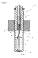
- FIG. 1 shows an injection valve 1 with a nozzle module 10 and an injector module 11.
- the injector module 11 functionally interacts with the nozzle module 10.
- the nozzle module 10 has a nozzle body 12 and the injector module 11 has an injector body 13.
- the nozzle body 12 and the injector body 13 are formed integrally and are embodied as a fuel tube.
- the nozzle body 12 and injector body 13 may be firmly bonded, e. g. by welding.
- the nozzle body 12 may be permanently fastened to the injector body 13 by means of an acorn nut.
- the nozzle body 12 and the injector body 13 thus form a common housing of the injection valve 1.
- a nozzle needle 18 with a central axis Z is arranged in a nozzle body recess 14, the latter forming the nozzle module 10 together with the nozzle body 12.
- the injection valve 1 comprises an actuator.
- the actuator is an electro-magnetic actuator in the present embodiment.
- the electro-magnetic actuator comprises an armature 16 and a solenoid 17.
- the solenoid 17 is arranged radially around the injector body 1313.
- the actuator is designed to actuate the nozzle needle 18.
- the actuator unit is activated according to a predetermined activation signal within a given activation period for effecting a fluid flow out of at least one first and at least one second injection nozzle 24, 25.
- the actuator can, however, also be embodied as another actuator which is known to the person skilled in the art for this purpose and is known to be suitable.
- the actuator may also be a piezoelectric actuator.
- the armature 16 is axially movable in the nozzle body recess 14.
- the armature 16 is coupled to the nozzle needle 18 to enable an axial movement of the nozzle needle 18.
- a nozzle spring 22 is arranged in a recess 26 provided in the injector body. Furthermore a filter element is arranged in the recess 26 of the injector body 13 and forms a further seat for the nozzle spring 22.
- the nozzle needle 18 is guided in an area of the nozzle body recess 14. It is also pre-stressed by means of the nozzle spring 22, such that it prevents fluid from flowing through the at least one first injection nozzle 24 and the at least one second injection nozzle 25 arranged in a nozzle cone 23 of the nozzle body 12, if no additional forces act on the nozzle needle 18.
- the nozzle needle 18 When actuating the actuator the nozzle needle 18 is firstly moved from its closed position into its open position, in which the nozzle needle 18 releases the fluid flow through the at least one first and the at least one second injection nozzle 24, 25.
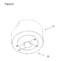
- Figure 2 exemplarily illustrates a schematic three-dimensional view of a fluid outlet part of the nozzle module 10, in particular the nozzle cone 23.
- Figure 2 shows an exemplary arrangement of at least one first injection nozzle 24 and at least one second injection nozzle 25 in the nozzle body 12.
- the nozzle body 12 comprises six first injection nozzles 24, which are arranged in the nozzle cone 23 and embodied as through-holes with a circular cross-sectional shape. These first injection nozzles 24 may comprise different cross-section diameters.
- the nozzle cone 23 of the nozzle body 12 shown in Figure 2 comprises one second injection nozzle 25, which is embodied as a through-hole with a cross-sectional shape differing from the cross-sectional shape of the at least one first injection nozzle.
- This second injection nozzle 25 may be embodied as a through-hole with a cross-sectional shape suitable to generate a flat injection jet.
- Such second injection nozzles 25 may be respectively embodied as a through-hole with a mainly elliptical and/or mainly rectangular and/or mainly groove-shaped and/or sickle-shaped cross-section.
- the nozzle body 12 may comprise more than the one second injection nozzle 25.
- the nozzle body 12 may comprise more than the one second injection nozzles 25, which have different cross-sectional shapes.
- the different cross-sectional shapes may differ in size and/or type.
- the at least one first injection nozzle 24 may comprise a through-hole with an inlet opening 56 and outlet opening 57 having different diameters.
- the first and/or second injection nozzle 24, 25 may taper down from the inlet opening 56 to the outlet opening 57.
- Figure 3 shows a first exemplary fuel spray pattern 60 of the nozzle module 10 of the injection valve 1.
- the nozzle body 12 comprises six of the first injection nozzles 24 and one of the second injection nozzles 25.
- Each of the first injection nozzles 24 generates the first injection jet 61 with a mainly conical shape.
- the second injection nozzle 25 generates the second injection jet 62 with a mainly sickle-shaped cross-section.
- a combustion chamber 75 of a combustion engine for example of a spark ignition engine with direct fuel injection (SIDI engine), is partially illustrated in a longitudinal-section view.
- a piston 71 is moveable in a closed end cylinder 73 and defines with the cylinder 73 a variable volume combustion chamber 75.
- the cylinder 73 comprises a longitudinal axis L.
- the combustion chamber 75 is configured with a spark plug 77 and an injection valve 1 cooperatively arranged such that the fuel spray pattern 60 from the injection vale will go very close to the spark plug gap.
- the exemplary combustion engine comprises at least one gas inlet valve 79 and at least one gas outlet valve (not shown).
- the spark plug 77 and the injection valve 1 are located offset in the cylinder head with respect to the longitudinal axis L of the cylinder 73.
- the nozzle module 10 of the injection valve 1 may comprise at least three, preferably at least four injection nozzles 24, 25, in particular seven or eight injection nozzles 24, 25.
- a typical total number of injection nozzles 24, 25 is four to eight.
- a certain number of injection nozzles 24, 25 ensures firstly as widespread as possible a distribution of the fuel in the combustion chamber 75, with which wide regions of the combustion chamber 75 are covered by the injection jets 61, 62, which is advantageous in particular with regard to the homogenization of the air/fuel mixture.
- the variation of the diameter and/or size and/or length of the injector nozzles may preferably be coordinated with the angle of inclination of the injection valve 1, that is to say the greater the degree to which the installation position of the injection valve 1 is inclined, the more pronounced the variation of the diameters and/or sizes and/or lengths may be. This corresponds to the fact that the impetuses of the injection jets 61, 62 differ to a greater extent with increasing angle of inclination.
- two of the at least one first injection nozzles 24 may be designed to generate long and thin jets to fill the combustion chamber 75 along the bigger dimension.
- one of the at least one first injection nozzles 24 may be designed and arranged to generate a short and thick jet to fill the combustion chamber 75 and/or to avoid impingement.
- One of the second injection nozzles 25 may be designed and arranged to generate a thin, film-shaped, jet with low penetration and good atomization close to the spark plug 75 for stratified operations.
Landscapes
- Engineering & Computer Science (AREA)
- Chemical & Material Sciences (AREA)
- Combustion & Propulsion (AREA)
- Mechanical Engineering (AREA)
- General Engineering & Computer Science (AREA)
- Fuel-Injection Apparatus (AREA)
Abstract
The nozzle module (10) for an injection valve (1) comprises a nozzle body (12), which has a seal seat, a nozzle body recess (14) and at least one first injection nozzle (24) and at least one second injection nozzle (25) which are hydraulically coupled with the nozzle body recess (14). The nozzle body recess (14) can be hydraulically coupled to a high pressure circuit of a fluid. The first injection nozzle (24) is embodied as a through-hole with a circular cross-sectional shape and the at least second injection nozzle (25) is embodied as a through-hole with a cross-sectional shape differing from the cross-sectional shape of the at least one first injection nozzle (24). Furthermore the nozzle module (10) comprises at least one nozzle needle (18) arranged in an axially moveable fashion in the nozzle body recess (14) with a central axis (Z), wherein the nozzle needle (18) comprises a seat area with a sealing surface and the sealing surface interacts with the seal seat such that in a closed position the nozzle needle (18) prevents fluid from flowing through the at least one first and second injection nozzle (24, 25) and in an open position releases a fluid flow through the at least one first and second injection nozzle (24, 25).
Description
- The invention relates to a nozzle module for an injection valve and the injection valve.
- Increasingly stringent statutory requirements relating to the permissible emission of harmful substances from internal combustion engines employed in motor vehicles make it necessary to adopt various measures by means of which the harmful emissions can be reduced. One approach here is to reduce the harmful emissions generated by the internal combustion engine. The formation of soot depends greatly on the preparation of the air/fuel mixture in the particular cylinder of the internal combustion engine.
- Fuel injectors are well-known devices for injecting fuel into engines, either into an intake manifold upstream of a combustion chamber, or directly into the combustion chamber. A correspondingly improved mixture preparation can be achieved if the fuel is metered at a very high pressure. A fuel spray of the fuel injector influences not only the combustion and power generation but also the generation of undesirable byproducts of combustion.
- The object of the invention is to create a nozzle module of an injection valve and an injection valve which facilitate an effective and precise injection of the injection valve and/or a cost-effective manufacturing of the nozzle module respectively of the injection valve.
- These objects are achieved by the features of the independent claims. Advantageous embodiments of the invention are given in the sub-claims.
- According to a first aspect the invention is distinguished by a nozzle module for an injection valve. The nozzle module comprises a nozzle body, which has a seal seat, a nozzle body recess and at least one first injection nozzle and at least one second injection nozzle which are hydraulically coupled with the nozzle body recess. The nozzle body recess can be hydraulically coupled to a high pressure circuit of a fluid. The first injection nozzle is embodied as a through-hole with a circular cross-sectional shape and the at least second injection nozzle is embodied as a through-hole with a cross-sectional shape differing from the cross-sectional shape of the at least one first injection nozzle. Furthermore the nozzle module comprises at least one nozzle needle arranged in an axially moveable fashion in the nozzle body recess with a central axis, wherein the nozzle needle comprises a seat area with a sealing surface and the sealing surface interacts with the seal seat such that in a closed position the nozzle needle prevents fluid from flowing through the at least one first and second injection nozzle and in an open position releases a fluid flow through the at least one first and second injection nozzle.
- This has the advantage, that a fuel spray pattern easily can be customized and/or optimized for different combustion engine types resulting in an improved combustion and power generation.
- For a drilling of the first and second injection nozzles new drilling technologies, e. g. laser drilling and/or electrical discharge machining (EDM) can be used. These technologies allow a very high precision and flexibility with regard to a hole shape and tolerances. Advantageously, the drilling of the at least first and second injection nozzles may be done in one production step, respectively.
- The nozzle module with at least more than one injection nozzle may ensure firstly as widespread as possible a distribution of the fuel in the combustion chamber, with which wide regions of the combustion chamber are covered by the injection jets, which is advantageous in particular with regard to the homogenization of the air/fuel mixture.
- The at least one first injection nozzle may comprise a through-hole with an outlet and inlet opening having different diameters. In particular, the first and/or second injection nozzle may taper down from the inlet opening to the outlet opening. The first and/or second injection nozzles may comprise different lengths, respectively.
- In an advantageous embodiment the at least one second injection nozzle is embodied as a through-hole with a cross-sectional shape suitable to generate a flat injection jet. This may allow generating a thin, film-shaped, jet with low penetration and good atomization close to the spark plug for stratified operations.
- In a further advantageous embodiment the at least second injection nozzle is embodied as a through-hole with a mainly elliptical and/or mainly rectangular and/or mainly groove-shaped and/or sickle-shaped cross-section. This may allow generating a thin, film-shaped, jet with low penetration and good atomization close to a spark plug for stratified operations.
- In a further advantageous embodiment the nozzle module comprises at least two first injection nozzles comprising different hole cross-sections. The variation of the diameter and/or size of the first or second injector nozzles can be coordinated with the angle of inclination of the injection valve mounted on a cylinder. According to a second aspect the invention is distinguished by an injection valve comprising a nozzle module according to the first aspect and an injector module, with the injector module being operable to act on the nozzle module.
- Exemplary embodiments of the invention are explained in the following with the aid of schematic drawings. These are as follows:
- Figure 1
- an injection valve in a longitudinal section view with a nozzle module,
- Figure 2
- a schematic three-dimensional view of a fluid outlet part of the nozzle module,
- Figure 3
- a first exemplary fuel spray pattern of the nozzle module of the injection valve and
- Figure 4
- a second exemplary fuel spray pattern in a combustion chamber of a combustion engine.
- Elements of the same design and function that appear in different illustrations are identified by the same reference character.
-
FIG. 1 shows aninjection valve 1 with anozzle module 10 and aninjector module 11. Theinjector module 11 functionally interacts with thenozzle module 10. - The
nozzle module 10 has anozzle body 12 and theinjector module 11 has aninjector body 13. Thenozzle body 12 and theinjector body 13 are formed integrally and are embodied as a fuel tube. Alternatively thenozzle body 12 andinjector body 13 may be firmly bonded, e. g. by welding. Alternatively, thenozzle body 12 may be permanently fastened to theinjector body 13 by means of an acorn nut. Thenozzle body 12 and theinjector body 13 thus form a common housing of theinjection valve 1. - A
nozzle needle 18 with a central axis Z is arranged in a nozzle body recess 14, the latter forming thenozzle module 10 together with thenozzle body 12. - The
injection valve 1 comprises an actuator. The actuator is an electro-magnetic actuator in the present embodiment. The electro-magnetic actuator comprises anarmature 16 and asolenoid 17. Thesolenoid 17 is arranged radially around the injector body 1313. The actuator is designed to actuate thenozzle needle 18. The actuator unit is activated according to a predetermined activation signal within a given activation period for effecting a fluid flow out of at least one first and at least onesecond injection nozzle - The
armature 16 is axially movable in the nozzle body recess 14. Thearmature 16 is coupled to thenozzle needle 18 to enable an axial movement of thenozzle needle 18. - A
nozzle spring 22 is arranged in arecess 26 provided in the injector body. Furthermore a filter element is arranged in therecess 26 of theinjector body 13 and forms a further seat for thenozzle spring 22. - The
nozzle needle 18 is guided in an area of the nozzle body recess 14. It is also pre-stressed by means of thenozzle spring 22, such that it prevents fluid from flowing through the at least onefirst injection nozzle 24 and the at least onesecond injection nozzle 25 arranged in anozzle cone 23 of thenozzle body 12, if no additional forces act on thenozzle needle 18. - When actuating the actuator the
nozzle needle 18 is firstly moved from its closed position into its open position, in which thenozzle needle 18 releases the fluid flow through the at least one first and the at least onesecond injection nozzle -
Figure 2 exemplarily illustrates a schematic three-dimensional view of a fluid outlet part of thenozzle module 10, in particular thenozzle cone 23.Figure 2 shows an exemplary arrangement of at least onefirst injection nozzle 24 and at least onesecond injection nozzle 25 in thenozzle body 12. - In
Figure 2 thenozzle body 12 comprises sixfirst injection nozzles 24, which are arranged in thenozzle cone 23 and embodied as through-holes with a circular cross-sectional shape. Thesefirst injection nozzles 24 may comprise different cross-section diameters. - The
nozzle cone 23 of thenozzle body 12 shown inFigure 2 , for instance, comprises onesecond injection nozzle 25, which is embodied as a through-hole with a cross-sectional shape differing from the cross-sectional shape of the at least one first injection nozzle. Thissecond injection nozzle 25 may be embodied as a through-hole with a cross-sectional shape suitable to generate a flat injection jet. Suchsecond injection nozzles 25 may be respectively embodied as a through-hole with a mainly elliptical and/or mainly rectangular and/or mainly groove-shaped and/or sickle-shaped cross-section. - The
nozzle body 12 may comprise more than the onesecond injection nozzle 25. In particular, thenozzle body 12 may comprise more than the onesecond injection nozzles 25, which have different cross-sectional shapes. The different cross-sectional shapes may differ in size and/or type. - The at least one
first injection nozzle 24 may comprise a through-hole with aninlet opening 56 and outlet opening 57 having different diameters. In particular the first and/orsecond injection nozzle outlet opening 57. -
Figure 3 shows a first exemplaryfuel spray pattern 60 of thenozzle module 10 of theinjection valve 1. In this case thenozzle body 12 comprises six of thefirst injection nozzles 24 and one of thesecond injection nozzles 25. Each of thefirst injection nozzles 24 generates thefirst injection jet 61 with a mainly conical shape. Thesecond injection nozzle 25 generates thesecond injection jet 62 with a mainly sickle-shaped cross-section. - In
figure 4 acombustion chamber 75 of a combustion engine, for example of a spark ignition engine with direct fuel injection (SIDI engine), is partially illustrated in a longitudinal-section view. Apiston 71 is moveable in aclosed end cylinder 73 and defines with the cylinder 73 a variablevolume combustion chamber 75. Thecylinder 73 comprises a longitudinal axis L. Thecombustion chamber 75 is configured with aspark plug 77 and aninjection valve 1 cooperatively arranged such that thefuel spray pattern 60 from the injection vale will go very close to the spark plug gap. The exemplary combustion engine comprises at least onegas inlet valve 79 and at least one gas outlet valve (not shown). Thespark plug 77 and theinjection valve 1 are located offset in the cylinder head with respect to the longitudinal axis L of thecylinder 73. - The
nozzle module 10 of theinjection valve 1 may comprise at least three, preferably at least fourinjection nozzles injection nozzles injection nozzles injection nozzles combustion chamber 75, with which wide regions of thecombustion chamber 75 are covered by theinjection jets - The variation of the diameter and/or size and/or length of the injector nozzles may preferably be coordinated with the angle of inclination of the
injection valve 1, that is to say the greater the degree to which the installation position of theinjection valve 1 is inclined, the more pronounced the variation of the diameters and/or sizes and/or lengths may be. This corresponds to the fact that the impetuses of theinjection jets - As shown in
figure 4 , e. g. two of the at least onefirst injection nozzles 24 may be designed to generate long and thin jets to fill thecombustion chamber 75 along the bigger dimension. For instance, one of the at least onefirst injection nozzles 24 may be designed and arranged to generate a short and thick jet to fill thecombustion chamber 75 and/or to avoid impingement. One of thesecond injection nozzles 25 may be designed and arranged to generate a thin, film-shaped, jet with low penetration and good atomization close to thespark plug 75 for stratified operations.
Claims (6)
- A nozzle module (10) for an injection valve (1), comprising- a nozzle body (12), which has a seal seat, a nozzle body recess (14) and at least one first injection nozzle (24) and at least one second injection nozzle (25), wherein the nozzle body recess (14) can be hydraulically coupled to a high pressure circuit of a fluid and the first injection nozzle (24) is embodied as a through-hole with a circular cross-sectional shape and the at least second injection nozzle (25) is embodied as a through-hole with a cross-sectional shape differing from the cross-section shape of the at least one first injection nozzle (24),- at least one nozzle needle (18) arranged in an axially moveable fashion in the nozzle body recess (14) with a central axis (Z), wherein the nozzle needle (18) comprises a seat area with a sealing surface and the sealing surface interacts with the seal seat such that in a closed position the nozzle needle (18) prevents fluid from flowing through the at least one first and second injection nozzle (24, 25) and in an open position releases a fluid flow through the at least one first and second injection nozzle (24, 25).
- Nozzle module (10) according to claim 1, wherein the at least one second injection nozzle (25) is embodied as a through-hole with a cross-sectional shape suitable to generate a flat injection jet.
- Nozzle module (10) according to claim 1 or 2, wherein the at least second injection nozzle (25) is embodied as a through-hole with a mainly elliptical and/or mainly rectangular and/or mainly groove-shaped and/or sickle-shaped cross-section.
- Nozzle module (10) according to claim 1 comprising at least two first injection nozzles (24) comprising different hole cross-sections.
- Injection valve (1) comprising a nozzle module (10) according to one of the claims 1 to 4 and an injector module 11, with the injector module 11 being operable to act on the nozzle module (10).
- Method for producing a nozzle module (10) according to one of claims 1 to 4, comprising a step of forming the at least one first injection nozzle (24) and at least one second injection nozzle (25) by means of laser drilling and/or electrical discharge machining.
Priority Applications (1)
| Application Number | Priority Date | Filing Date | Title |
|---|---|---|---|
| EP12185581.1A EP2711536A1 (en) | 2012-09-24 | 2012-09-24 | Nozzle module and injection valve |
Applications Claiming Priority (1)
| Application Number | Priority Date | Filing Date | Title |
|---|---|---|---|
| EP12185581.1A EP2711536A1 (en) | 2012-09-24 | 2012-09-24 | Nozzle module and injection valve |
Publications (1)
| Publication Number | Publication Date |
|---|---|
| EP2711536A1 true EP2711536A1 (en) | 2014-03-26 |
Family
ID=46970064
Family Applications (1)
| Application Number | Title | Priority Date | Filing Date |
|---|---|---|---|
| EP12185581.1A Withdrawn EP2711536A1 (en) | 2012-09-24 | 2012-09-24 | Nozzle module and injection valve |
Country Status (1)
| Country | Link |
|---|---|
| EP (1) | EP2711536A1 (en) |
Cited By (2)
| Publication number | Priority date | Publication date | Assignee | Title |
|---|---|---|---|---|
| EP2829720A1 (en) * | 2013-07-22 | 2015-01-28 | Delphi Technologies, Inc. | Fuel injector |
| US9551311B2 (en) | 2014-07-17 | 2017-01-24 | Continental Automotive Gmbh | Nozzle body, the valve assembly and fluid injection valve |
Citations (6)
| Publication number | Priority date | Publication date | Assignee | Title |
|---|---|---|---|---|
| FR2229868A1 (en) * | 1973-05-15 | 1974-12-13 | Cav Ltd | Plunger type fuel injector nozzle - has length of hole through nozzle end adjustable to vary spray angle |
| US4857696A (en) * | 1987-06-12 | 1989-08-15 | Raycon Textron Inc. | Laser/EDM drilling manufacturing cell |
| WO2001090571A2 (en) * | 2000-05-26 | 2001-11-29 | Robert Bosch Gmbh | Fuel injection system |
| FR2860558A1 (en) * | 2003-10-06 | 2005-04-08 | Renault Sas | INTERNAL COMBUSTION ENGINE INJECTOR FOR A VEHICLE COMPRISING A NOZZLE PROVIDED WITH AN EXTERNAL ORIFICE |
| FR2860557A1 (en) * | 2003-10-06 | 2005-04-08 | Renault Sa | INTERNAL COMBUSTION ENGINE FUEL INJECTOR FOR A VEHICLE COMPRISING A NOZZLE HAVING AT LEAST ONE ORIFICE |
| DE102009047704A1 (en) * | 2009-12-09 | 2011-06-16 | Robert Bosch Gmbh | Fuel injection valve |
-
2012
- 2012-09-24 EP EP12185581.1A patent/EP2711536A1/en not_active Withdrawn
Patent Citations (6)
| Publication number | Priority date | Publication date | Assignee | Title |
|---|---|---|---|---|
| FR2229868A1 (en) * | 1973-05-15 | 1974-12-13 | Cav Ltd | Plunger type fuel injector nozzle - has length of hole through nozzle end adjustable to vary spray angle |
| US4857696A (en) * | 1987-06-12 | 1989-08-15 | Raycon Textron Inc. | Laser/EDM drilling manufacturing cell |
| WO2001090571A2 (en) * | 2000-05-26 | 2001-11-29 | Robert Bosch Gmbh | Fuel injection system |
| FR2860558A1 (en) * | 2003-10-06 | 2005-04-08 | Renault Sas | INTERNAL COMBUSTION ENGINE INJECTOR FOR A VEHICLE COMPRISING A NOZZLE PROVIDED WITH AN EXTERNAL ORIFICE |
| FR2860557A1 (en) * | 2003-10-06 | 2005-04-08 | Renault Sa | INTERNAL COMBUSTION ENGINE FUEL INJECTOR FOR A VEHICLE COMPRISING A NOZZLE HAVING AT LEAST ONE ORIFICE |
| DE102009047704A1 (en) * | 2009-12-09 | 2011-06-16 | Robert Bosch Gmbh | Fuel injection valve |
Cited By (3)
| Publication number | Priority date | Publication date | Assignee | Title |
|---|---|---|---|---|
| EP2829720A1 (en) * | 2013-07-22 | 2015-01-28 | Delphi Technologies, Inc. | Fuel injector |
| US9850869B2 (en) | 2013-07-22 | 2017-12-26 | Delphi Technologies, Inc. | Fuel injector |
| US9551311B2 (en) | 2014-07-17 | 2017-01-24 | Continental Automotive Gmbh | Nozzle body, the valve assembly and fluid injection valve |
Similar Documents
| Publication | Publication Date | Title |
|---|---|---|
| CN1175180C (en) | Method for making a discharge port on a valve | |
| JP4200137B2 (en) | Fuel injection valve | |
| US20080217439A1 (en) | Fuel injector | |
| US20080105767A1 (en) | Fuel injection apparatus | |
| US8313048B2 (en) | Fuel injector | |
| EP1900934A1 (en) | Fuel Injector | |
| JP4123938B2 (en) | Fuel injection system | |
| US20040129806A1 (en) | Fuel injection valve | |
| EP2829720A1 (en) | Fuel injector | |
| JP4804188B2 (en) | Injector mounting structure and fuel injection device | |
| CN100447401C (en) | fuel injection valve | |
| CN1461383A (en) | Fuel injection valve | |
| US6824085B2 (en) | Fuel injector | |
| JP4306656B2 (en) | Fuel injection valve | |
| US20120223164A1 (en) | Nozzle assembly for an injection valve and injection valve | |
| JP2016519253A (en) | Fuel injector | |
| JP4058377B2 (en) | Fuel injection valve | |
| US20030111562A1 (en) | Fuel injection valve | |
| EP2896811B1 (en) | Nozzle assembly and fuel injection valve for a combustion engine | |
| JP2003184706A (en) | Fuel injection valve | |
| US20070176132A1 (en) | Valve Assembly For An Injection Valve And Injection Valve | |
| EP1467087B1 (en) | Spray pattern element and fuel injection valve with a spray pattern element | |
| JP4038767B2 (en) | Fuel injection device | |
| JP4036175B2 (en) | Fuel injection valve | |
| KR102112492B1 (en) | Injection valve |
Legal Events
| Date | Code | Title | Description |
|---|---|---|---|
| PUAI | Public reference made under article 153(3) epc to a published international application that has entered the european phase |
Free format text: ORIGINAL CODE: 0009012 |
|
| AK | Designated contracting states |
Kind code of ref document: A1 Designated state(s): AL AT BE BG CH CY CZ DE DK EE ES FI FR GB GR HR HU IE IS IT LI LT LU LV MC MK MT NL NO PL PT RO RS SE SI SK SM TR |
|
| AX | Request for extension of the european patent |
Extension state: BA ME |
|
| STAA | Information on the status of an ep patent application or granted ep patent |
Free format text: STATUS: THE APPLICATION IS DEEMED TO BE WITHDRAWN |
|
| 18D | Application deemed to be withdrawn |
Effective date: 20140927 |