EP2711516A2 - Exhaust cleaning system including a wet exhaust system and cooling a catalyst - Google Patents
Exhaust cleaning system including a wet exhaust system and cooling a catalyst Download PDFInfo
- Publication number
- EP2711516A2 EP2711516A2 EP13183090.3A EP13183090A EP2711516A2 EP 2711516 A2 EP2711516 A2 EP 2711516A2 EP 13183090 A EP13183090 A EP 13183090A EP 2711516 A2 EP2711516 A2 EP 2711516A2
- Authority
- EP
- European Patent Office
- Prior art keywords
- housing
- catalyst
- fitting
- cooling
- cooling housing
- Prior art date
- Legal status (The legal status is an assumption and is not a legal conclusion. Google has not performed a legal analysis and makes no representation as to the accuracy of the status listed.)
- Granted
Links
Images


Classifications
-
- F—MECHANICAL ENGINEERING; LIGHTING; HEATING; WEAPONS; BLASTING
- F01—MACHINES OR ENGINES IN GENERAL; ENGINE PLANTS IN GENERAL; STEAM ENGINES
- F01N—GAS-FLOW SILENCERS OR EXHAUST APPARATUS FOR MACHINES OR ENGINES IN GENERAL; GAS-FLOW SILENCERS OR EXHAUST APPARATUS FOR INTERNAL-COMBUSTION ENGINES
- F01N3/00—Exhaust or silencing apparatus having means for purifying, rendering innocuous, or otherwise treating exhaust
- F01N3/02—Exhaust or silencing apparatus having means for purifying, rendering innocuous, or otherwise treating exhaust for cooling, or for removing solid constituents of, exhaust
- F01N3/04—Exhaust or silencing apparatus having means for purifying, rendering innocuous, or otherwise treating exhaust for cooling, or for removing solid constituents of, exhaust using liquids
-
- F—MECHANICAL ENGINEERING; LIGHTING; HEATING; WEAPONS; BLASTING
- F01—MACHINES OR ENGINES IN GENERAL; ENGINE PLANTS IN GENERAL; STEAM ENGINES
- F01N—GAS-FLOW SILENCERS OR EXHAUST APPARATUS FOR MACHINES OR ENGINES IN GENERAL; GAS-FLOW SILENCERS OR EXHAUST APPARATUS FOR INTERNAL-COMBUSTION ENGINES
- F01N13/00—Exhaust or silencing apparatus characterised by constructional features
- F01N13/18—Construction facilitating manufacture, assembly, or disassembly
- F01N13/1838—Construction facilitating manufacture, assembly, or disassembly characterised by the type of connection between parts of exhaust or silencing apparatus, e.g. between housing and tubes, between tubes and baffles
- F01N13/1844—Mechanical joints
- F01N13/185—Mechanical joints the connection being realised by deforming housing, tube, baffle, plate, or parts thereof
-
- F—MECHANICAL ENGINEERING; LIGHTING; HEATING; WEAPONS; BLASTING
- F01—MACHINES OR ENGINES IN GENERAL; ENGINE PLANTS IN GENERAL; STEAM ENGINES
- F01N—GAS-FLOW SILENCERS OR EXHAUST APPARATUS FOR MACHINES OR ENGINES IN GENERAL; GAS-FLOW SILENCERS OR EXHAUST APPARATUS FOR INTERNAL-COMBUSTION ENGINES
- F01N3/00—Exhaust or silencing apparatus having means for purifying, rendering innocuous, or otherwise treating exhaust
- F01N3/02—Exhaust or silencing apparatus having means for purifying, rendering innocuous, or otherwise treating exhaust for cooling, or for removing solid constituents of, exhaust
- F01N3/05—Exhaust or silencing apparatus having means for purifying, rendering innocuous, or otherwise treating exhaust for cooling, or for removing solid constituents of, exhaust by means of air, e.g. by mixing exhaust with air
-
- F—MECHANICAL ENGINEERING; LIGHTING; HEATING; WEAPONS; BLASTING
- F01—MACHINES OR ENGINES IN GENERAL; ENGINE PLANTS IN GENERAL; STEAM ENGINES
- F01N—GAS-FLOW SILENCERS OR EXHAUST APPARATUS FOR MACHINES OR ENGINES IN GENERAL; GAS-FLOW SILENCERS OR EXHAUST APPARATUS FOR INTERNAL-COMBUSTION ENGINES
- F01N3/00—Exhaust or silencing apparatus having means for purifying, rendering innocuous, or otherwise treating exhaust
- F01N3/08—Exhaust or silencing apparatus having means for purifying, rendering innocuous, or otherwise treating exhaust for rendering innocuous
- F01N3/10—Exhaust or silencing apparatus having means for purifying, rendering innocuous, or otherwise treating exhaust for rendering innocuous by thermal or catalytic conversion of noxious components of exhaust
- F01N3/24—Exhaust or silencing apparatus having means for purifying, rendering innocuous, or otherwise treating exhaust for rendering innocuous by thermal or catalytic conversion of noxious components of exhaust characterised by constructional aspects of converting apparatus
- F01N3/28—Construction of catalytic reactors
- F01N3/2803—Construction of catalytic reactors characterised by structure, by material or by manufacturing of catalyst support
-
- F—MECHANICAL ENGINEERING; LIGHTING; HEATING; WEAPONS; BLASTING
- F01—MACHINES OR ENGINES IN GENERAL; ENGINE PLANTS IN GENERAL; STEAM ENGINES
- F01N—GAS-FLOW SILENCERS OR EXHAUST APPARATUS FOR MACHINES OR ENGINES IN GENERAL; GAS-FLOW SILENCERS OR EXHAUST APPARATUS FOR INTERNAL-COMBUSTION ENGINES
- F01N3/00—Exhaust or silencing apparatus having means for purifying, rendering innocuous, or otherwise treating exhaust
- F01N3/08—Exhaust or silencing apparatus having means for purifying, rendering innocuous, or otherwise treating exhaust for rendering innocuous
- F01N3/10—Exhaust or silencing apparatus having means for purifying, rendering innocuous, or otherwise treating exhaust for rendering innocuous by thermal or catalytic conversion of noxious components of exhaust
- F01N3/24—Exhaust or silencing apparatus having means for purifying, rendering innocuous, or otherwise treating exhaust for rendering innocuous by thermal or catalytic conversion of noxious components of exhaust characterised by constructional aspects of converting apparatus
- F01N3/28—Construction of catalytic reactors
- F01N3/2839—Arrangements for mounting catalyst support in housing, e.g. with means for compensating thermal expansion or vibration
- F01N3/2842—Arrangements for mounting catalyst support in housing, e.g. with means for compensating thermal expansion or vibration specially adapted for monolithic supports, e.g. of honeycomb type
-
- F—MECHANICAL ENGINEERING; LIGHTING; HEATING; WEAPONS; BLASTING
- F01—MACHINES OR ENGINES IN GENERAL; ENGINE PLANTS IN GENERAL; STEAM ENGINES
- F01N—GAS-FLOW SILENCERS OR EXHAUST APPARATUS FOR MACHINES OR ENGINES IN GENERAL; GAS-FLOW SILENCERS OR EXHAUST APPARATUS FOR INTERNAL-COMBUSTION ENGINES
- F01N2260/00—Exhaust treating devices having provisions not otherwise provided for
- F01N2260/02—Exhaust treating devices having provisions not otherwise provided for for cooling the device
- F01N2260/022—Exhaust treating devices having provisions not otherwise provided for for cooling the device using air
-
- F—MECHANICAL ENGINEERING; LIGHTING; HEATING; WEAPONS; BLASTING
- F01—MACHINES OR ENGINES IN GENERAL; ENGINE PLANTS IN GENERAL; STEAM ENGINES
- F01N—GAS-FLOW SILENCERS OR EXHAUST APPARATUS FOR MACHINES OR ENGINES IN GENERAL; GAS-FLOW SILENCERS OR EXHAUST APPARATUS FOR INTERNAL-COMBUSTION ENGINES
- F01N2260/00—Exhaust treating devices having provisions not otherwise provided for
- F01N2260/02—Exhaust treating devices having provisions not otherwise provided for for cooling the device
- F01N2260/024—Exhaust treating devices having provisions not otherwise provided for for cooling the device using a liquid
-
- F—MECHANICAL ENGINEERING; LIGHTING; HEATING; WEAPONS; BLASTING
- F01—MACHINES OR ENGINES IN GENERAL; ENGINE PLANTS IN GENERAL; STEAM ENGINES
- F01N—GAS-FLOW SILENCERS OR EXHAUST APPARATUS FOR MACHINES OR ENGINES IN GENERAL; GAS-FLOW SILENCERS OR EXHAUST APPARATUS FOR INTERNAL-COMBUSTION ENGINES
- F01N2450/00—Methods or apparatus for fitting, inserting or repairing different elements
- F01N2450/02—Fitting monolithic blocks into the housing
-
- F—MECHANICAL ENGINEERING; LIGHTING; HEATING; WEAPONS; BLASTING
- F01—MACHINES OR ENGINES IN GENERAL; ENGINE PLANTS IN GENERAL; STEAM ENGINES
- F01N—GAS-FLOW SILENCERS OR EXHAUST APPARATUS FOR MACHINES OR ENGINES IN GENERAL; GAS-FLOW SILENCERS OR EXHAUST APPARATUS FOR INTERNAL-COMBUSTION ENGINES
- F01N2450/00—Methods or apparatus for fitting, inserting or repairing different elements
- F01N2450/20—Methods or apparatus for fitting, inserting or repairing different elements by mechanical joints, e.g. by deforming housing, tube, baffle plate or parts thereof
-
- F—MECHANICAL ENGINEERING; LIGHTING; HEATING; WEAPONS; BLASTING
- F01—MACHINES OR ENGINES IN GENERAL; ENGINE PLANTS IN GENERAL; STEAM ENGINES
- F01N—GAS-FLOW SILENCERS OR EXHAUST APPARATUS FOR MACHINES OR ENGINES IN GENERAL; GAS-FLOW SILENCERS OR EXHAUST APPARATUS FOR INTERNAL-COMBUSTION ENGINES
- F01N2470/00—Structure or shape of exhaust gas passages, pipes or tubes
- F01N2470/24—Concentric tubes or tubes being concentric to housing, e.g. telescopically assembled
-
- F—MECHANICAL ENGINEERING; LIGHTING; HEATING; WEAPONS; BLASTING
- F01—MACHINES OR ENGINES IN GENERAL; ENGINE PLANTS IN GENERAL; STEAM ENGINES
- F01N—GAS-FLOW SILENCERS OR EXHAUST APPARATUS FOR MACHINES OR ENGINES IN GENERAL; GAS-FLOW SILENCERS OR EXHAUST APPARATUS FOR INTERNAL-COMBUSTION ENGINES
- F01N2590/00—Exhaust or silencing apparatus adapted to particular use, e.g. for military applications, airplanes, submarines
- F01N2590/02—Exhaust or silencing apparatus adapted to particular use, e.g. for military applications, airplanes, submarines for marine vessels or naval applications
-
- Y—GENERAL TAGGING OF NEW TECHNOLOGICAL DEVELOPMENTS; GENERAL TAGGING OF CROSS-SECTIONAL TECHNOLOGIES SPANNING OVER SEVERAL SECTIONS OF THE IPC; TECHNICAL SUBJECTS COVERED BY FORMER USPC CROSS-REFERENCE ART COLLECTIONS [XRACs] AND DIGESTS
- Y02—TECHNOLOGIES OR APPLICATIONS FOR MITIGATION OR ADAPTATION AGAINST CLIMATE CHANGE
- Y02T—CLIMATE CHANGE MITIGATION TECHNOLOGIES RELATED TO TRANSPORTATION
- Y02T10/00—Road transport of goods or passengers
- Y02T10/10—Internal combustion engine [ICE] based vehicles
- Y02T10/12—Improving ICE efficiencies
-
- Y—GENERAL TAGGING OF NEW TECHNOLOGICAL DEVELOPMENTS; GENERAL TAGGING OF CROSS-SECTIONAL TECHNOLOGIES SPANNING OVER SEVERAL SECTIONS OF THE IPC; TECHNICAL SUBJECTS COVERED BY FORMER USPC CROSS-REFERENCE ART COLLECTIONS [XRACs] AND DIGESTS
- Y10—TECHNICAL SUBJECTS COVERED BY FORMER USPC
- Y10T—TECHNICAL SUBJECTS COVERED BY FORMER US CLASSIFICATION
- Y10T29/00—Metal working
- Y10T29/49—Method of mechanical manufacture
- Y10T29/49229—Prime mover or fluid pump making
Definitions
- Embodiments pertain to a power management system that includes a an exhaust system, and more particularly to a power management system that includes a wet exhaust system.
- Some existing power management systems typically includes exhaust systems that project a combination of gaseous and liquid emissions that are produced as part of operating an engine (especially a marine engine). These types of systems that emit both gaseous and liquid emissions are referred to as wet exhaust systems.
- One of the important factors in wet exhaust systems is to reduce the amount of harmful emissions that are produced during operation of the engine.
- the amount of harmful emissions is typically reduced in existing systems by including a catalytic substrate that intercepts and converts harmful gaseous emissions into less harmful elements.
- Some existing systems attempt to cool the exhaust gases after the gases are converted by the catalytic substrate but before the converted gases exit the wet exhaust system.
- the exhaust gases need to remain as hot as possible before entering the catalytic substrate in order to promote more efficient conversion by the catalytic substrate.
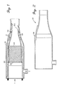
- FIG. 1 illustrates an example catalytic assembly for an engine.
- FIG.2 is a schematic section view of an example cooling housing that may be used in the catalytic assembly shown in FIG. 1 .
- FIG.3 is a perspective view of the example cooling housing shown in FIG. 2 .
- FIG.4 is a schematic section view of an example catalyst housing that may be used in the catalytic assembly shown in FIG. 1 .
- FIG.5 is a perspective view of the example catalyst housing shown in FIG. 4 .
- FIG. 6 shows an example baffle that may be used in the catalytic assembly shown in FIG. 1 .
- FIG. 7 shows an example restraining member that may be used in the catalytic assembly shown in FIG. 1 before the restraining member is inserted into the catalyst housing.
- FIG. 8 shows the restraining member of FIG. 7 after the restraining member is inserted into the catalyst housing but before the restraining member is inserted into an annular groove in the catalyst housing.
- FIG. 9 shows the restraining member of FIG. 7 after the restraining member is inserted into the annular groove in the catalyst housing.
- FIG. 10 shows a partial perspective section view where the restraining member of FIG. 7 is inserted into the annular groove in the catalyst housing.
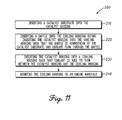
- FIG. 11 illustrates an example method of assembling a catalyst assembly.
- FIG. 1 illustrates an example catalytic assembly 100 for an engine (not shown).
- the catalytic assembly 100 includes a cooling housing 110 that receives a coolant C (e.g., seawater).
- FIGS. 2 and 3 show the cooling housing 110 separate from the rest of the catalytic assembly 100.
- a catalyst housing 120 is disposed within the cooling housing 110 such that the coolant C flows between the catalyst housing 120 and the cooling housing 120.
- FIGS.4 and 5 show the catalyst housing 120 separate from the rest of the catalytic assembly 100.
- a catalyst substrate 130 (see FIG. 1 ) is positioned within the catalyst housing 120 such that exhaust gases E from the engine flows through the catalyst substrate 130.
- the catalyst substrate 130 serves to covert harmful emissions found in the exhaust gases E to less harmful emissions.
- a baffle 140 is positioned between the catalyst housing 120 and the cooling housing 110 downstream of the catalyst substrate 130 such that coolant C flows through the baffle 140.
- FIG. 6 shows most clearly an example baffle 140 that may be included in the catalytic assembly 100.
- the baffle 140 may be formed of stainless steel, although other materials are contemplated.
- the baffle 140 may include an annular member 141 and projections 142 extending from the annular member 141 at angle to the annular member 141.
- the baffle 140 includes openings 143 between the projections 142 such that coolant flows through the openings 143.
- the baffle 140 may include eight openings 143 such that coolant flows through the eight openings 143.
- the openings 143 may be positioned at equal (or unequal) intervals around the annular member 141.
- the catalyst housing 120 includes a first fitting 121 and cooling housing 110 includes a second fitting 111 that mates with the first fitting 121 to prevent rotation of the catalyst housing 120 relative to the cooling housing 110.
- first fitting 121 is a detent and the second fitting 111 is a projection (e.g. a key) that is inserted into the detent.
- first fitting 121 and second fitting 111 that are used in the respective catalyst housing 120 and cooling housing 110 depend in part on overall design of the catalytic assembly 100.
- first fitting 121 is a projection and the second fitting 111 is a detent that receives the projection.
- first fitting 121 on the catalyst housing 120 may be inserted (or received depending on the design) into the second fitting 111 on the cooling housing 110 until the first fitting 121 and the second fitting 111 prevent further insertion of the catalyst housing 120 into the cooling housing 110.
- the catalytic assembly 100 further includes a restraining member 150 that is secured within an annular groove 125 in the catalyst housing 120 to secure the catalyst substrate 130 within the catalyst housing 120.
- FIGS. 7-10 illustrate an example disc-shaped ring 150 that permits exhaust to flow through the ring 150 into the catalyst substrate 130.
- the ring 150 may be formed of stainless steel, although it should be noted that other materials are contemplated.
- the annular groove 125 extends around an entire inner surface of the catalyst housing 120.
- FIG. 7 shows the ring 150 before insertion into the catalyst housing 120.
- FIG. 8 shows the ring 150 after insertion into the catalyst housing 120 but before insertion into the annular groove 125.
- FIGS. 9 and 10 show the ring 150 after insertion into the annular groove 125 in the catalyst housing 120.
- the method 200 includes [210] inserting a catalyst substrate 130 into a catalyst housing 120 and [230] inserting a catalyst housing 120 into a cooling housing 110 such that coolant C is able to flow between the catalyst housing 120 and the cooling housing 110.
- the method 200 further includes [240] mounting the cooling housing 110 to an engine manifold (not shown).
- the method may further include [220] inserting a baffle 140 into the cooling housing 110 before inserting the catalyst housing 120 into the cooling housing 110 such that the baffle 140 is downstream of the catalyst substrate 130 and coolant flows through the baffle 140.
- inserting a catalyst housing 120 into the cooling housing 110 may include mating a first fitting 121 on the catalyst housing 120 with a second fitting 111 on the cooling housing 110.
- mating the first fitting 121 on the catalyst housing 120 with the second fitting 111 on the cooling housing 110 may include inserting a projection on the catalyst housing 120 into a detent on the cooling housing 110 to prevent rotation of the catalyst housing 120 relative to the cooling housing 110.
- mating the first fitting 121 on the catalyst housing 120 with the second fitting 111 on the cooling housing 110 may include inserting a projection on the cooling housing 120 into a detent on the catalyst housing 111 to prevent rotation of the catalyst housing 120 relative to the cooling housing 110.
- mating a first fitting 121 on the catalyst housing 120 with a second fitting 111 on the cooling housing 110 may include preventing further insertion of the catalyst housing 120 into the cooling housing 110.
- the catalytic assemblies 100 and methods 200 described herein may serve to prevent the catalytic substrate 130 from overcooling during operation of the engine. Preventing overcooling of the catalytic substrate 130 may increase the conversion efficiency of the catalytic substrate 130.
- the catalytic assemblies 100 and methods 200 described herein may promote cost reduction and manufacturability. Decreasing the cost associated with fabricating the catalytic assemblies 100 may reduce the cost of producing products that include the catalytic assemblies 100.
Landscapes
- Engineering & Computer Science (AREA)
- Chemical & Material Sciences (AREA)
- Chemical Kinetics & Catalysis (AREA)
- Combustion & Propulsion (AREA)
- Mechanical Engineering (AREA)
- General Engineering & Computer Science (AREA)
- Health & Medical Sciences (AREA)
- Toxicology (AREA)
- Exhaust Gas After Treatment (AREA)
Abstract
Description
- Embodiments pertain to a power management system that includes a an exhaust system, and more particularly to a power management system that includes a wet exhaust system.
- Some existing power management systems typically includes exhaust systems that project a combination of gaseous and liquid emissions that are produced as part of operating an engine (especially a marine engine). These types of systems that emit both gaseous and liquid emissions are referred to as wet exhaust systems.
- One of the important factors in wet exhaust systems is to reduce the amount of harmful emissions that are produced during operation of the engine. The amount of harmful emissions is typically reduced in existing systems by including a catalytic substrate that intercepts and converts harmful gaseous emissions into less harmful elements.
- Some existing systems attempt to cool the exhaust gases after the gases are converted by the catalytic substrate but before the converted gases exit the wet exhaust system. The exhaust gases need to remain as hot as possible before entering the catalytic substrate in order to promote more efficient conversion by the catalytic substrate.
- One of the drawbacks with existing power management systems is that catalytic substrate is overcooled due to the design of such systems. This overcooling of the catalytic substrate decreases the conversion efficiency of the substrate.
- Another drawback with existing power management systems is that they are typically relatively expensive and complicated to manufacture. This increased cost associated with fabricating such systems adds unwanted cost to producing products that include wet exhaust systems.
-
FIG. 1 illustrates an example catalytic assembly for an engine. -
FIG.2 is a schematic section view of an example cooling housing that may be used in the catalytic assembly shown inFIG. 1 . -
FIG.3 is a perspective view of the example cooling housing shown inFIG. 2 . -
FIG.4 is a schematic section view of an example catalyst housing that may be used in the catalytic assembly shown inFIG. 1 . -
FIG.5 is a perspective view of the example catalyst housing shown inFIG. 4 . -
FIG. 6 shows an example baffle that may be used in the catalytic assembly shown inFIG. 1 . - SNAP RING
-
FIG. 7 shows an example restraining member that may be used in the catalytic assembly shown inFIG. 1 before the restraining member is inserted into the catalyst housing. -
FIG. 8 shows the restraining member ofFIG. 7 after the restraining member is inserted into the catalyst housing but before the restraining member is inserted into an annular groove in the catalyst housing. -
FIG. 9 shows the restraining member ofFIG. 7 after the restraining member is inserted into the annular groove in the catalyst housing. -
FIG. 10 shows a partial perspective section view where the restraining member ofFIG. 7 is inserted into the annular groove in the catalyst housing. -
FIG. 11 illustrates an example method of assembling a catalyst assembly. - The following description and the drawings sufficiently illustrate specific embodiments to enable those skilled in the art to practice them. Other embodiments may incorporate structural, logical, electrical, process, and other changes. Portions and features of some embodiments may be included in, or substituted for, those of other embodiments. Embodiments set forth in the claims encompass all available equivalents of those claims.
-
FIG. 1 illustrates an example catalytic assembly 100 for an engine (not shown). The catalytic assembly 100 includes acooling housing 110 that receives a coolant C (e.g., seawater).FIGS. 2 and3 show thecooling housing 110 separate from the rest of the catalytic assembly 100. - A
catalyst housing 120 is disposed within thecooling housing 110 such that the coolant C flows between thecatalyst housing 120 and thecooling housing 120.FIGS.4 and5 show thecatalyst housing 120 separate from the rest of the catalytic assembly 100. - A catalyst substrate 130 (see
FIG. 1 ) is positioned within thecatalyst housing 120 such that exhaust gases E from the engine flows through thecatalyst substrate 130. Thecatalyst substrate 130 serves to covert harmful emissions found in the exhaust gases E to less harmful emissions. - In some embodiments, a
baffle 140 is positioned between thecatalyst housing 120 and thecooling housing 110 downstream of thecatalyst substrate 130 such that coolant C flows through thebaffle 140.FIG. 6 shows most clearly anexample baffle 140 that may be included in the catalytic assembly 100. As an example, thebaffle 140 may be formed of stainless steel, although other materials are contemplated. - In the example embodiment that is illustrated in
FIG. 6 , thebaffle 140 may include anannular member 141 andprojections 142 extending from theannular member 141 at angle to theannular member 141. Thebaffle 140 includesopenings 143 between theprojections 142 such that coolant flows through theopenings 143. - As an example, the
baffle 140 may include eightopenings 143 such that coolant flows through the eightopenings 143. In addition, theopenings 143 may be positioned at equal (or unequal) intervals around theannular member 141. - In some embodiments, the
catalyst housing 120 includes a first fitting 121 andcooling housing 110 includes a second fitting 111 that mates with thefirst fitting 121 to prevent rotation of thecatalyst housing 120 relative to thecooling housing 110. - In the illustrated example embodiments, the
first fitting 121 is a detent and thesecond fitting 111 is a projection (e.g. a key) that is inserted into the detent. It should be noted that the type of first fitting 121 andsecond fitting 111 that are used in therespective catalyst housing 120 andcooling housing 110 depend in part on overall design of the catalytic assembly 100. - Alternative embodiments are contemplated where the
first fitting 121 is a projection and thesecond fitting 111 is a detent that receives the projection. In still other embodiments, the first fitting 121 on thecatalyst housing 120 may be inserted (or received depending on the design) into thesecond fitting 111 on thecooling housing 110 until the first fitting 121 and thesecond fitting 111 prevent further insertion of the catalyst housing 120 into thecooling housing 110. - In some embodiments, the catalytic assembly 100 further includes a
restraining member 150 that is secured within anannular groove 125 in thecatalyst housing 120 to secure thecatalyst substrate 130 within thecatalyst housing 120.FIGS. 7-10 illustrate an example disc-shaped ring 150 that permits exhaust to flow through thering 150 into thecatalyst substrate 130. As an example, thering 150 may be formed of stainless steel, although it should be noted that other materials are contemplated. - In the illustrated example embodiments, the
annular groove 125 extends around an entire inner surface of thecatalyst housing 120.FIG. 7 shows thering 150 before insertion into thecatalyst housing 120.FIG. 8 shows thering 150 after insertion into thecatalyst housing 120 but before insertion into theannular groove 125.FIGS. 9 and 10 show thering 150 after insertion into theannular groove 125 in thecatalyst housing 120. - Referring now also to
FIG. 11 , another example embodiment relates to amethod 200 of assembling a catalyst assembly 100. Themethod 200 includes [210] inserting acatalyst substrate 130 into acatalyst housing 120 and [230] inserting acatalyst housing 120 into acooling housing 110 such that coolant C is able to flow between thecatalyst housing 120 and thecooling housing 110. - The
method 200 further includes [240] mounting thecooling housing 110 to an engine manifold (not shown). The method may further include [220] inserting abaffle 140 into thecooling housing 110 before inserting thecatalyst housing 120 into thecooling housing 110 such that thebaffle 140 is downstream of thecatalyst substrate 130 and coolant flows through thebaffle 140. - In some embodiments, [230] inserting a
catalyst housing 120 into thecooling housing 110 may include mating afirst fitting 121 on thecatalyst housing 120 with a second fitting 111 on thecooling housing 110. As an example, mating thefirst fitting 121 on thecatalyst housing 120 with thesecond fitting 111 on thecooling housing 110 may include inserting a projection on thecatalyst housing 120 into a detent on thecooling housing 110 to prevent rotation of thecatalyst housing 120 relative to thecooling housing 110. - It should be noted that embodiments are contemplated where mating the
first fitting 121 on thecatalyst housing 120 with thesecond fitting 111 on thecooling housing 110 may include inserting a projection on thecooling housing 120 into a detent on thecatalyst housing 111 to prevent rotation of thecatalyst housing 120 relative to thecooling housing 110. In addition, mating afirst fitting 121 on thecatalyst housing 120 with a second fitting 111 on thecooling housing 110 may include preventing further insertion of thecatalyst housing 120 into thecooling housing 110. - The catalytic assemblies 100 and
methods 200 described herein may serve to prevent thecatalytic substrate 130 from overcooling during operation of the engine. Preventing overcooling of thecatalytic substrate 130 may increase the conversion efficiency of thecatalytic substrate 130. - In addition, the catalytic assemblies 100 and
methods 200 described herein may promote cost reduction and manufacturability. Decreasing the cost associated with fabricating the catalytic assemblies 100 may reduce the cost of producing products that include the catalytic assemblies 100. - The Abstract is provided to comply with 37 C.F.R. Section 1.72(b) requiring an abstract that will allow the reader to ascertain the nature and gist of the technical disclosure. It is submitted with the understanding that it will not be used to limit or interpret the scope or meaning of the claims. The following claims are hereby incorporated into the detailed description, with each claim standing on its own as a separate embodiment.
Claims (16)
- A catalytic assembly comprising:a cooling housing that receives a coolant;a catalyst housing disposed within the cooling housing such that coolant flows between the catalyst housing and the cooling housing, wherein the catalyst housing includes a first fitting; anda catalyst substrate within the catalyst housing such that exhaust flows through the substrate, wherein the catalyst housing includes a second fitting that mates with the first fitting to prevent rotation of the catalyst housing relative to the cooling housing.
- The catalytic assembly of claim 1 wherein the first fitting is a detent and the second fitting is a projection that is inserted into the detent.
- The catalytic assembly of claim 2 wherein the projection is a key.
- The catalytic assembly of claim 1 wherein the first fitting is a projection and the second fitting is a detent that is inserted into the projection.
- The catalytic assembly of claim 1 wherein when the first fitting is inserted mated with the second fitting the catalyst housing is prevented from further insertion into the cooling housing.
- A catalytic assembly comprising:a cooling housing that receives a coolant;a catalyst housing disposed within the cooling housing such that coolant flows between the catalyst housing and the cooling housing;a catalyst substrate within the catalyst housing such that exhaust flows through the substrate; anda restraining member secured within an annular groove in the catalyst housing to secure the catalyst substrate within the catalyst housing.
- The catalytic assembly of claim 6 wherein the restraining member is disc-shaped.
- The catalytic assembly of claim 6 wherein the restraining member is a ring that permits exhaust to flow through the ring into the catalyst substrate.
- The catalytic assembly of claim 6 wherein restraining member is formed of plastic.
- The catalytic assembly of claim 6 wherein the annular groove extends around an entire inner surface of the catalyst housing.
- A method of assembling a catalyst assembly, the method comprising:inserting a catalyst substrate into the catalyst housing;inserting the catalyst housing into a cooling housing such that coolant is able to flow between the catalyst housing and the cooling housing; andmounting the cooling housing to an engine manifold.
- The method of claim 11 further comprising inserting a baffle into the cooling housing before inserting the catalyst housing into the cooling housing such that the baffle is downstream of the catalyst substrate and coolant flows through the baffle.
- The method of claim 11 wherein inserting a catalyst housing into the cooling housing includes mating a first fitting on the catalyst housing with a second fitting on the cooling housing.
- The method of claim 13 wherein mating the first fitting on the catalyst housing with the second fitting on the cooling housing includes inserting a projection on the catalyst housing into a detent on the cooling housing to prevent rotation of the catalyst housing relative to the cooling housing.
- The method of claim 13 wherein mating the first fitting on the catalyst housing with the second fitting on the cooling housing includes inserting a projection on the cooling housing into a detent on the catalyst housing to prevent rotation of the catalyst housing relative to the cooling housing.
- The method of claim 15 wherein mating a first fitting on the catalyst housing with a second fitting on the cooling housing includes preventing further insertion of the catalyst housing into the cooling housing.
Applications Claiming Priority (1)
| Application Number | Priority Date | Filing Date | Title |
|---|---|---|---|
| US13/624,082 US9328641B2 (en) | 2012-09-21 | 2012-09-21 | Power management system that includes a wet exhaust system |
Publications (3)
| Publication Number | Publication Date |
|---|---|
| EP2711516A2 true EP2711516A2 (en) | 2014-03-26 |
| EP2711516A3 EP2711516A3 (en) | 2014-04-23 |
| EP2711516B1 EP2711516B1 (en) | 2016-10-26 |
Family
ID=49165523
Family Applications (1)
| Application Number | Title | Priority Date | Filing Date |
|---|---|---|---|
| EP13183090.3A Not-in-force EP2711516B1 (en) | 2012-09-21 | 2013-09-05 | Exhaust cleaning system including a wet exhaust system and cooling a catalyst |
Country Status (3)
| Country | Link |
|---|---|
| US (1) | US9328641B2 (en) |
| EP (1) | EP2711516B1 (en) |
| CN (1) | CN103670618B (en) |
Cited By (2)
| Publication number | Priority date | Publication date | Assignee | Title |
|---|---|---|---|---|
| EP3221568A4 (en) * | 2014-11-19 | 2018-05-30 | Envirochasing Ip Holdings Pty Ltd. | Extraction apparatus |
| WO2018234027A1 (en) * | 2017-06-19 | 2018-12-27 | Volkswagen Aktiengesellschaft | Exhaust pipe, internal combustion engine, and motor vehicle |
Families Citing this family (3)
| Publication number | Priority date | Publication date | Assignee | Title |
|---|---|---|---|---|
| DE102015209681B4 (en) | 2015-05-27 | 2023-05-17 | Purem GmbH | Exhaust gas treatment device with exchangeable insert |
| US9957863B2 (en) | 2016-06-27 | 2018-05-01 | Indmar Products Company, Inc. | Exhaust conduits for marine engine exhaust systems |
| US10464652B2 (en) | 2018-01-23 | 2019-11-05 | Indmar Products Company Inc. | Riser conduits having inner tube extensions for marine engine exhaust systems |
Family Cites Families (60)
| Publication number | Priority date | Publication date | Assignee | Title |
|---|---|---|---|---|
| FR2201710A5 (en) | 1972-10-03 | 1974-04-26 | Peugeot & Renault | |
| US3817714A (en) * | 1972-10-10 | 1974-06-18 | Corning Glass Works | Catalytic converter |
| US4032310A (en) | 1974-05-15 | 1977-06-28 | Ignoffo Vincent E | Muffler and exhaust gas purifier for internal combustion engines |
| US4207661A (en) | 1976-04-23 | 1980-06-17 | Honda Giken Kogyo Kabushiki Kaisha | Method of fabricating a catalyst converter for cleaning exhausts of cars |
| US4049388A (en) * | 1976-07-12 | 1977-09-20 | Arvin Industries, Inc. | Center air manifold for catalytic converter |
| US4142864A (en) | 1977-05-31 | 1979-03-06 | Engelhard Minerals & Chemicals Corporation | Catalytic apparatus |
| US4347219A (en) | 1979-12-29 | 1982-08-31 | Honda Giken Kogyo Kabushiki Kaisha | Catalytic converter for exhaust-gas cleaning use and method of assembling same |
| JPS56162220A (en) | 1980-05-20 | 1981-12-14 | Ngk Insulators Ltd | Ceramic honeycomb structural body |
| US4397817A (en) | 1980-08-20 | 1983-08-09 | Honda Giken Kogyo Kabushiki Kaisha | Catalytic converter |
| US4420933A (en) | 1981-06-03 | 1983-12-20 | Honda Giken Kogyo Kabushiki Kaisha | Exhaust system |
| US4382808A (en) | 1981-06-26 | 1983-05-10 | Beckman Instruments, Inc. | Assembly for holding a filter |
| JPS5941621A (en) | 1982-08-31 | 1984-03-07 | Toyota Motor Corp | Monolith catalytic converter |
| DE3343587A1 (en) | 1983-12-02 | 1984-07-12 | Daimler-Benz Ag, 7000 Stuttgart | Silencer for flowing gases |
| US4663934A (en) | 1985-04-01 | 1987-05-12 | Arvin Industries, Inc. | Manifold exhaust processor |
| US4711088A (en) | 1987-01-08 | 1987-12-08 | Chrysler Motors Corporation | Liquid cooled exhaust manifold |
| JP2984027B2 (en) | 1990-05-22 | 1999-11-29 | 三信工業株式会社 | Exhaust purification system for ship propulsion |
| US5220789A (en) | 1991-03-05 | 1993-06-22 | Ford Motor Company | Integral unitary manifold-muffler-catalyst device |
| US5148675A (en) | 1991-04-26 | 1992-09-22 | Inman Frederick R | Marine exhaust manifold and header pipe system |
| US5555621A (en) | 1993-03-11 | 1996-09-17 | Calsonic Corporation | Method of producing a catalytic converter |
| US5290974A (en) * | 1993-03-12 | 1994-03-01 | Arvin Industries, Inc. | Tab and notch locator for exhaust systems |
| US5408827A (en) | 1993-09-28 | 1995-04-25 | Outboard Marine Corporation | Marine propulsion device with improved catalyst support arrangement |
| US5431706A (en) | 1993-10-05 | 1995-07-11 | Dry Systems Technologies | Disposable particulate filter |
| JPH0842333A (en) | 1994-06-06 | 1996-02-13 | Ford Motor Co | Preparation of catalyst exhaust treating device |
| US5740670A (en) | 1995-04-10 | 1998-04-21 | Woods; Woodrow | Water jacketed exhaust pipe for marine exhaust systems |
| EP0761939A1 (en) | 1995-08-16 | 1997-03-12 | General Motors Corporation | Manifold converter |
| US5656245A (en) | 1995-11-14 | 1997-08-12 | Nippon Reinz Co., Ltd. | Catalytic converter for cleaning exhaust gas |
| DE19608870C1 (en) | 1996-03-07 | 1997-10-23 | Daimler Benz Ag | Vehicle internal combustion engine exhaust gas conduit insert |
| JP3501899B2 (en) | 1996-04-15 | 2004-03-02 | ヤマハ発動機株式会社 | Exhaust system for ship propulsion |
| JP3395533B2 (en) | 1996-08-09 | 2003-04-14 | トヨタ自動車株式会社 | Diesel engine exhaust purification system |
| SE508622C2 (en) | 1997-11-21 | 1998-10-19 | Nilcon Eng Ab | Catalyst with cam flange for clamping |
| US5881554A (en) | 1998-03-23 | 1999-03-16 | Ford Global Technologies, Inc. | Integrated manifold, muffler, and catalyst device |
| US5911683A (en) | 1998-04-02 | 1999-06-15 | Zeuna-Starker Gmbh & Co. Kg | Exhaust-gas collecting and cleaning device as well as exhaust-gas device for a multi-cylinder engine |
| JP3328588B2 (en) | 1998-07-23 | 2002-09-24 | 日本碍子株式会社 | Gas flow path |
| DE19905032A1 (en) | 1999-02-08 | 2000-08-10 | Emitec Emissionstechnologie | Exhaust system with at least one guide surface |
| JP3589078B2 (en) | 1999-03-18 | 2004-11-17 | 日産自動車株式会社 | Catalyst carrier holding device for catalytic converter |
| JP3613061B2 (en) | 1999-03-18 | 2005-01-26 | 日産自動車株式会社 | Elastic washer for catalytic converter and catalyst carrier holding structure of catalytic converter |
| US6397589B1 (en) | 1999-08-31 | 2002-06-04 | Custom Marine, Inc. | Exhaust pipes and assemblies |
| US7311066B1 (en) | 2000-05-22 | 2007-12-25 | Wbip, Llc | Controlling exhaust temperatures |
| US7241426B2 (en) | 2000-12-15 | 2007-07-10 | Delphi Technologies, Inc. | Exhaust manifold with catalytic converter shell tube |
| JP2003184547A (en) | 2001-12-18 | 2003-07-03 | Yamaha Marine Co Ltd | Small vessel |
| US6840034B2 (en) | 2002-04-19 | 2005-01-11 | Envirolift, Llc | Emission control apparatus for marine generator engine |
| US6799422B2 (en) | 2002-08-22 | 2004-10-05 | Westerbeke Corporation | Emissions control |
| US6946013B2 (en) | 2002-10-28 | 2005-09-20 | Geo2 Technologies, Inc. | Ceramic exhaust filter |
| US6892531B2 (en) | 2003-04-02 | 2005-05-17 | Julius J. Rim | System for and methods of operating diesel engines to reduce harmful exhaust emissions and to improve engine lubrication |
| DE10325030B4 (en) | 2003-06-02 | 2012-09-27 | Dr. Ing. H.C. F. Porsche Aktiengesellschaft | Exhaust system for a motor vehicle |
| JP2007510094A (en) | 2003-10-27 | 2007-04-19 | ウエスタートビーク コーポレーション | Engine control system for exhaust emission reduction |
| US20050150222A1 (en) | 2003-12-30 | 2005-07-14 | Kalish Martin W. | One piece catalytic converter with integral exhaust manifold |
| JP2007154660A (en) | 2005-11-30 | 2007-06-21 | Futaba Industrial Co Ltd | Exhaust manifold |
| US7552586B1 (en) | 2005-12-12 | 2009-06-30 | Brunswick Corporation | Marine exhaust system with a downstream oxygen sensor located away from a water reversion liquid trajectory path |
| US20100112878A1 (en) | 2005-12-12 | 2010-05-06 | Brunswick Corporation | Catalyst device for a marine engine which is generally tubular with a rim portion |
| US7708953B2 (en) | 2006-01-11 | 2010-05-04 | Cummins Filtration Ip, Inc. | Apparatus and system for ensuring proper assembly of an exhaust system |
| US7788913B2 (en) | 2006-02-16 | 2010-09-07 | Indmar Products Company Inc. | Manifold mounted catalytic converter |
| FR2905405B1 (en) | 2006-09-01 | 2008-11-07 | Renault Sas | ARRANGEMENT FOR CONNECTING A DUCT TO A DEPOLLUTION MEMBER OF AN EXHAUST LINE OF A COMBUSTION ENGINE |
| DE102007026108A1 (en) | 2007-06-05 | 2008-12-11 | Robert Bosch Gmbh | Filter and catalyst element |
| DE102008011558B4 (en) | 2007-12-12 | 2010-04-01 | GEA MASCHINENKüHLTECHNIK GMBH | heat exchangers |
| WO2009086486A1 (en) | 2007-12-27 | 2009-07-09 | In The Works... | High-efficiency catalytic converters for treating exhaust gases |
| US20100229540A1 (en) | 2009-03-11 | 2010-09-16 | Indmar Products Company Inc. | Combination Liquid-Cooled Exhaust Manifold Assembly And Catalytic Converter Assembly For A Marine Engine |
| JP2010241333A (en) | 2009-04-08 | 2010-10-28 | Yamaha Motor Co Ltd | Water jet propulsion boat |
| TW201117977A (en) * | 2009-11-20 | 2011-06-01 | zhong-yu Yang | Air intake device for engine of vehicle |
| CN201705432U (en) * | 2010-07-07 | 2011-01-12 | 广西玉柴机器股份有限公司 | Diesel engine aft-vortex exhausting cooling mechanism |
-
2012
- 2012-09-21 US US13/624,082 patent/US9328641B2/en active Active
-
2013
- 2013-09-05 EP EP13183090.3A patent/EP2711516B1/en not_active Not-in-force
- 2013-09-16 CN CN201310421622.7A patent/CN103670618B/en not_active Expired - Fee Related
Non-Patent Citations (1)
| Title |
|---|
| None |
Cited By (4)
| Publication number | Priority date | Publication date | Assignee | Title |
|---|---|---|---|---|
| EP3221568A4 (en) * | 2014-11-19 | 2018-05-30 | Envirochasing Ip Holdings Pty Ltd. | Extraction apparatus |
| US10641145B2 (en) | 2014-11-19 | 2020-05-05 | Envirochasing Ip Holdings Pty Ltd | Extraction apparatus |
| WO2018234027A1 (en) * | 2017-06-19 | 2018-12-27 | Volkswagen Aktiengesellschaft | Exhaust pipe, internal combustion engine, and motor vehicle |
| US11149605B2 (en) | 2017-06-19 | 2021-10-19 | Volkswagen Aktiengesellschaft | Exhaust pipe, combustion engine machine, and motor vehicle |
Also Published As
| Publication number | Publication date |
|---|---|
| EP2711516A3 (en) | 2014-04-23 |
| US20140086804A1 (en) | 2014-03-27 |
| CN103670618A (en) | 2014-03-26 |
| US9328641B2 (en) | 2016-05-03 |
| CN103670618B (en) | 2016-06-01 |
| EP2711516B1 (en) | 2016-10-26 |
Similar Documents
| Publication | Publication Date | Title |
|---|---|---|
| US9328641B2 (en) | Power management system that includes a wet exhaust system | |
| EP2196648A1 (en) | Engine exhaust heat recovery device and energy supply device using the same | |
| US8440155B2 (en) | Flow modulating substrates for early light-off | |
| JP6208192B2 (en) | Exhaust gas treatment equipment | |
| EP2966263B1 (en) | Turbocharger | |
| US20150128582A1 (en) | One-way plate and stator support structure for torque converter using same | |
| KR20160043914A (en) | Heat shield with centering features | |
| TW200925390A (en) | Stator vane for a gas turbine engine | |
| EP3098407A1 (en) | Reducing-agent injector gasket and exhaust-gas posttreatment apparatus including same | |
| US10337530B2 (en) | Press on heat/splash and engine cooling fan assembly having same | |
| EP2211025B1 (en) | Discrete Load Fins For Individual Stator Vanes | |
| US7540714B1 (en) | Device for blocking a ring for axially retaining a blade, associated rotor disk and retaining ring, and rotor and aircraft engine comprising them | |
| US9371768B2 (en) | Exhaust system member | |
| JP5146579B2 (en) | Bearing device and method for assembling bearing device | |
| EP3225806B1 (en) | Expansion tank for a motor-vehicle cooling system | |
| US12603540B2 (en) | Rotary electric machine, with fluid distribution chamber between stator and housing | |
| JP2019009009A (en) | Battery cooling system | |
| CN114087061A (en) | Tail gas aftertreatment device | |
| US20250376936A1 (en) | Doser mount for exhaust aftertreatment system | |
| CN216691228U (en) | Tail gas aftertreatment device | |
| CN217538822U (en) | Mixing tube assembly | |
| CN113803145A (en) | Tail gas aftertreatment encapsulation | |
| MX2018004093A (en) | A cooling system for an internal combustion engine. | |
| JP2016142145A (en) | Exhaust pipe | |
| US10710704B2 (en) | Fairing ring for a bladed wheel |
Legal Events
| Date | Code | Title | Description |
|---|---|---|---|
| PUAL | Search report despatched |
Free format text: ORIGINAL CODE: 0009013 |
|
| PUAI | Public reference made under article 153(3) epc to a published international application that has entered the european phase |
Free format text: ORIGINAL CODE: 0009012 |
|
| AK | Designated contracting states |
Kind code of ref document: A2 Designated state(s): AL AT BE BG CH CY CZ DE DK EE ES FI FR GB GR HR HU IE IS IT LI LT LU LV MC MK MT NL NO PL PT RO RS SE SI SK SM TR |
|
| AX | Request for extension of the european patent |
Extension state: BA ME |
|
| AK | Designated contracting states |
Kind code of ref document: A3 Designated state(s): AL AT BE BG CH CY CZ DE DK EE ES FI FR GB GR HR HU IE IS IT LI LT LU LV MC MK MT NL NO PL PT RO RS SE SI SK SM TR |
|
| AX | Request for extension of the european patent |
Extension state: BA ME |
|
| RIC1 | Information provided on ipc code assigned before grant |
Ipc: F01N 13/18 20100101ALI20140317BHEP Ipc: F01N 3/28 20060101ALI20140317BHEP Ipc: F01N 3/04 20060101AFI20140317BHEP Ipc: F01N 3/05 20060101ALI20140317BHEP |
|
| 17P | Request for examination filed |
Effective date: 20141021 |
|
| RBV | Designated contracting states (corrected) |
Designated state(s): AL AT BE BG CH CY CZ DE DK EE ES FI FR GB GR HR HU IE IS IT LI LT LU LV MC MK MT NL NO PL PT RO RS SE SI SK SM TR |
|
| 17Q | First examination report despatched |
Effective date: 20150630 |
|
| GRAP | Despatch of communication of intention to grant a patent |
Free format text: ORIGINAL CODE: EPIDOSNIGR1 |
|
| INTG | Intention to grant announced |
Effective date: 20160506 |
|
| GRAS | Grant fee paid |
Free format text: ORIGINAL CODE: EPIDOSNIGR3 |
|
| GRAA | (expected) grant |
Free format text: ORIGINAL CODE: 0009210 |
|
| AK | Designated contracting states |
Kind code of ref document: B1 Designated state(s): AL AT BE BG CH CY CZ DE DK EE ES FI FR GB GR HR HU IE IS IT LI LT LU LV MC MK MT NL NO PL PT RO RS SE SI SK SM TR |
|
| REG | Reference to a national code |
Ref country code: GB Ref legal event code: FG4D |
|
| REG | Reference to a national code |
Ref country code: CH Ref legal event code: EP |
|
| REG | Reference to a national code |
Ref country code: AT Ref legal event code: REF Ref document number: 840198 Country of ref document: AT Kind code of ref document: T Effective date: 20161115 |
|
| REG | Reference to a national code |
Ref country code: IE Ref legal event code: FG4D |
|
| REG | Reference to a national code |
Ref country code: DE Ref legal event code: R096 Ref document number: 602013013158 Country of ref document: DE |
|
| REG | Reference to a national code |
Ref country code: LT Ref legal event code: MG4D |
|
| PG25 | Lapsed in a contracting state [announced via postgrant information from national office to epo] |
Ref country code: LV Free format text: LAPSE BECAUSE OF FAILURE TO SUBMIT A TRANSLATION OF THE DESCRIPTION OR TO PAY THE FEE WITHIN THE PRESCRIBED TIME-LIMIT Effective date: 20161026 |
|
| REG | Reference to a national code |
Ref country code: NL Ref legal event code: MP Effective date: 20161026 |
|
| REG | Reference to a national code |
Ref country code: AT Ref legal event code: MK05 Ref document number: 840198 Country of ref document: AT Kind code of ref document: T Effective date: 20161026 |
|
| PG25 | Lapsed in a contracting state [announced via postgrant information from national office to epo] |
Ref country code: SE Free format text: LAPSE BECAUSE OF FAILURE TO SUBMIT A TRANSLATION OF THE DESCRIPTION OR TO PAY THE FEE WITHIN THE PRESCRIBED TIME-LIMIT Effective date: 20161026 Ref country code: LT Free format text: LAPSE BECAUSE OF FAILURE TO SUBMIT A TRANSLATION OF THE DESCRIPTION OR TO PAY THE FEE WITHIN THE PRESCRIBED TIME-LIMIT Effective date: 20161026 Ref country code: NO Free format text: LAPSE BECAUSE OF FAILURE TO SUBMIT A TRANSLATION OF THE DESCRIPTION OR TO PAY THE FEE WITHIN THE PRESCRIBED TIME-LIMIT Effective date: 20170126 Ref country code: GR Free format text: LAPSE BECAUSE OF FAILURE TO SUBMIT A TRANSLATION OF THE DESCRIPTION OR TO PAY THE FEE WITHIN THE PRESCRIBED TIME-LIMIT Effective date: 20170127 |
|
| PG25 | Lapsed in a contracting state [announced via postgrant information from national office to epo] |
Ref country code: HR Free format text: LAPSE BECAUSE OF FAILURE TO SUBMIT A TRANSLATION OF THE DESCRIPTION OR TO PAY THE FEE WITHIN THE PRESCRIBED TIME-LIMIT Effective date: 20161026 Ref country code: ES Free format text: LAPSE BECAUSE OF FAILURE TO SUBMIT A TRANSLATION OF THE DESCRIPTION OR TO PAY THE FEE WITHIN THE PRESCRIBED TIME-LIMIT Effective date: 20161026 Ref country code: FI Free format text: LAPSE BECAUSE OF FAILURE TO SUBMIT A TRANSLATION OF THE DESCRIPTION OR TO PAY THE FEE WITHIN THE PRESCRIBED TIME-LIMIT Effective date: 20161026 Ref country code: PL Free format text: LAPSE BECAUSE OF FAILURE TO SUBMIT A TRANSLATION OF THE DESCRIPTION OR TO PAY THE FEE WITHIN THE PRESCRIBED TIME-LIMIT Effective date: 20161026 Ref country code: RS Free format text: LAPSE BECAUSE OF FAILURE TO SUBMIT A TRANSLATION OF THE DESCRIPTION OR TO PAY THE FEE WITHIN THE PRESCRIBED TIME-LIMIT Effective date: 20161026 Ref country code: IS Free format text: LAPSE BECAUSE OF FAILURE TO SUBMIT A TRANSLATION OF THE DESCRIPTION OR TO PAY THE FEE WITHIN THE PRESCRIBED TIME-LIMIT Effective date: 20170226 Ref country code: BE Free format text: LAPSE BECAUSE OF FAILURE TO SUBMIT A TRANSLATION OF THE DESCRIPTION OR TO PAY THE FEE WITHIN THE PRESCRIBED TIME-LIMIT Effective date: 20161026 Ref country code: NL Free format text: LAPSE BECAUSE OF FAILURE TO SUBMIT A TRANSLATION OF THE DESCRIPTION OR TO PAY THE FEE WITHIN THE PRESCRIBED TIME-LIMIT Effective date: 20161026 Ref country code: AT Free format text: LAPSE BECAUSE OF FAILURE TO SUBMIT A TRANSLATION OF THE DESCRIPTION OR TO PAY THE FEE WITHIN THE PRESCRIBED TIME-LIMIT Effective date: 20161026 Ref country code: PT Free format text: LAPSE BECAUSE OF FAILURE TO SUBMIT A TRANSLATION OF THE DESCRIPTION OR TO PAY THE FEE WITHIN THE PRESCRIBED TIME-LIMIT Effective date: 20170227 |
|
| REG | Reference to a national code |
Ref country code: DE Ref legal event code: R097 Ref document number: 602013013158 Country of ref document: DE |
|
| PG25 | Lapsed in a contracting state [announced via postgrant information from national office to epo] |
Ref country code: EE Free format text: LAPSE BECAUSE OF FAILURE TO SUBMIT A TRANSLATION OF THE DESCRIPTION OR TO PAY THE FEE WITHIN THE PRESCRIBED TIME-LIMIT Effective date: 20161026 Ref country code: DK Free format text: LAPSE BECAUSE OF FAILURE TO SUBMIT A TRANSLATION OF THE DESCRIPTION OR TO PAY THE FEE WITHIN THE PRESCRIBED TIME-LIMIT Effective date: 20161026 Ref country code: SK Free format text: LAPSE BECAUSE OF FAILURE TO SUBMIT A TRANSLATION OF THE DESCRIPTION OR TO PAY THE FEE WITHIN THE PRESCRIBED TIME-LIMIT Effective date: 20161026 Ref country code: CZ Free format text: LAPSE BECAUSE OF FAILURE TO SUBMIT A TRANSLATION OF THE DESCRIPTION OR TO PAY THE FEE WITHIN THE PRESCRIBED TIME-LIMIT Effective date: 20161026 Ref country code: RO Free format text: LAPSE BECAUSE OF FAILURE TO SUBMIT A TRANSLATION OF THE DESCRIPTION OR TO PAY THE FEE WITHIN THE PRESCRIBED TIME-LIMIT Effective date: 20161026 |
|
| REG | Reference to a national code |
Ref country code: FR Ref legal event code: PLFP Year of fee payment: 5 |
|
| PG25 | Lapsed in a contracting state [announced via postgrant information from national office to epo] |
Ref country code: BG Free format text: LAPSE BECAUSE OF FAILURE TO SUBMIT A TRANSLATION OF THE DESCRIPTION OR TO PAY THE FEE WITHIN THE PRESCRIBED TIME-LIMIT Effective date: 20170126 Ref country code: SM Free format text: LAPSE BECAUSE OF FAILURE TO SUBMIT A TRANSLATION OF THE DESCRIPTION OR TO PAY THE FEE WITHIN THE PRESCRIBED TIME-LIMIT Effective date: 20161026 Ref country code: IT Free format text: LAPSE BECAUSE OF FAILURE TO SUBMIT A TRANSLATION OF THE DESCRIPTION OR TO PAY THE FEE WITHIN THE PRESCRIBED TIME-LIMIT Effective date: 20161026 |
|
| PLBE | No opposition filed within time limit |
Free format text: ORIGINAL CODE: 0009261 |
|
| STAA | Information on the status of an ep patent application or granted ep patent |
Free format text: STATUS: NO OPPOSITION FILED WITHIN TIME LIMIT |
|
| 26N | No opposition filed |
Effective date: 20170727 |
|
| PGFP | Annual fee paid to national office [announced via postgrant information from national office to epo] |
Ref country code: FR Payment date: 20170810 Year of fee payment: 5 |
|
| PG25 | Lapsed in a contracting state [announced via postgrant information from national office to epo] |
Ref country code: SI Free format text: LAPSE BECAUSE OF FAILURE TO SUBMIT A TRANSLATION OF THE DESCRIPTION OR TO PAY THE FEE WITHIN THE PRESCRIBED TIME-LIMIT Effective date: 20161026 |
|
| REG | Reference to a national code |
Ref country code: DE Ref legal event code: R119 Ref document number: 602013013158 Country of ref document: DE |
|
| REG | Reference to a national code |
Ref country code: CH Ref legal event code: PL |
|
| GBPC | Gb: european patent ceased through non-payment of renewal fee |
Effective date: 20170905 |
|
| PG25 | Lapsed in a contracting state [announced via postgrant information from national office to epo] |
Ref country code: MC Free format text: LAPSE BECAUSE OF FAILURE TO SUBMIT A TRANSLATION OF THE DESCRIPTION OR TO PAY THE FEE WITHIN THE PRESCRIBED TIME-LIMIT Effective date: 20161026 |
|
| REG | Reference to a national code |
Ref country code: IE Ref legal event code: MM4A |
|
| PG25 | Lapsed in a contracting state [announced via postgrant information from national office to epo] |
Ref country code: LU Free format text: LAPSE BECAUSE OF NON-PAYMENT OF DUE FEES Effective date: 20170905 |
|
| PG25 | Lapsed in a contracting state [announced via postgrant information from national office to epo] |
Ref country code: DE Free format text: LAPSE BECAUSE OF NON-PAYMENT OF DUE FEES Effective date: 20180404 Ref country code: GB Free format text: LAPSE BECAUSE OF NON-PAYMENT OF DUE FEES Effective date: 20170905 Ref country code: CH Free format text: LAPSE BECAUSE OF NON-PAYMENT OF DUE FEES Effective date: 20170930 Ref country code: IE Free format text: LAPSE BECAUSE OF NON-PAYMENT OF DUE FEES Effective date: 20170905 Ref country code: LI Free format text: LAPSE BECAUSE OF NON-PAYMENT OF DUE FEES Effective date: 20170930 |
|
| PG25 | Lapsed in a contracting state [announced via postgrant information from national office to epo] |
Ref country code: MT Free format text: LAPSE BECAUSE OF NON-PAYMENT OF DUE FEES Effective date: 20170905 |
|
| PG25 | Lapsed in a contracting state [announced via postgrant information from national office to epo] |
Ref country code: HU Free format text: LAPSE BECAUSE OF FAILURE TO SUBMIT A TRANSLATION OF THE DESCRIPTION OR TO PAY THE FEE WITHIN THE PRESCRIBED TIME-LIMIT; INVALID AB INITIO Effective date: 20130905 |
|
| PG25 | Lapsed in a contracting state [announced via postgrant information from national office to epo] |
Ref country code: FR Free format text: LAPSE BECAUSE OF NON-PAYMENT OF DUE FEES Effective date: 20180930 |
|
| PG25 | Lapsed in a contracting state [announced via postgrant information from national office to epo] |
Ref country code: CY Free format text: LAPSE BECAUSE OF NON-PAYMENT OF DUE FEES Effective date: 20161026 |
|
| PG25 | Lapsed in a contracting state [announced via postgrant information from national office to epo] |
Ref country code: MK Free format text: LAPSE BECAUSE OF FAILURE TO SUBMIT A TRANSLATION OF THE DESCRIPTION OR TO PAY THE FEE WITHIN THE PRESCRIBED TIME-LIMIT Effective date: 20161026 |
|
| PG25 | Lapsed in a contracting state [announced via postgrant information from national office to epo] |
Ref country code: TR Free format text: LAPSE BECAUSE OF FAILURE TO SUBMIT A TRANSLATION OF THE DESCRIPTION OR TO PAY THE FEE WITHIN THE PRESCRIBED TIME-LIMIT Effective date: 20161026 |
|
| PG25 | Lapsed in a contracting state [announced via postgrant information from national office to epo] |
Ref country code: AL Free format text: LAPSE BECAUSE OF FAILURE TO SUBMIT A TRANSLATION OF THE DESCRIPTION OR TO PAY THE FEE WITHIN THE PRESCRIBED TIME-LIMIT Effective date: 20161026 |