EP2711266A2 - Steering Apparatus - Google Patents
Steering Apparatus Download PDFInfo
- Publication number
- EP2711266A2 EP2711266A2 EP20130184670 EP13184670A EP2711266A2 EP 2711266 A2 EP2711266 A2 EP 2711266A2 EP 20130184670 EP20130184670 EP 20130184670 EP 13184670 A EP13184670 A EP 13184670A EP 2711266 A2 EP2711266 A2 EP 2711266A2
- Authority
- EP
- European Patent Office
- Prior art keywords
- section
- hinge shaft
- tilt hinge
- steering
- housing
- Prior art date
- Legal status (The legal status is an assumption and is not a legal conclusion. Google has not performed a legal analysis and makes no representation as to the accuracy of the status listed.)
- Granted
Links
Images


Classifications
-
- B—PERFORMING OPERATIONS; TRANSPORTING
- B62—LAND VEHICLES FOR TRAVELLING OTHERWISE THAN ON RAILS
- B62D—MOTOR VEHICLES; TRAILERS
- B62D1/00—Steering controls, i.e. means for initiating a change of direction of the vehicle
- B62D1/02—Steering controls, i.e. means for initiating a change of direction of the vehicle vehicle-mounted
- B62D1/16—Steering columns
- B62D1/18—Steering columns yieldable or adjustable, e.g. tiltable
- B62D1/187—Steering columns yieldable or adjustable, e.g. tiltable with tilt adjustment; with tilt and axial adjustment
-
- B—PERFORMING OPERATIONS; TRANSPORTING
- B60—VEHICLES IN GENERAL
- B60R—VEHICLES, VEHICLE FITTINGS, OR VEHICLE PARTS, NOT OTHERWISE PROVIDED FOR
- B60R16/00—Electric or fluid circuits specially adapted for vehicles and not otherwise provided for; Arrangement of elements of electric or fluid circuits specially adapted for vehicles and not otherwise provided for
- B60R16/02—Electric or fluid circuits specially adapted for vehicles and not otherwise provided for; Arrangement of elements of electric or fluid circuits specially adapted for vehicles and not otherwise provided for electric constitutive elements
- B60R16/023—Electric or fluid circuits specially adapted for vehicles and not otherwise provided for; Arrangement of elements of electric or fluid circuits specially adapted for vehicles and not otherwise provided for electric constitutive elements for transmission of signals between vehicle parts or subsystems
- B60R16/027—Electric or fluid circuits specially adapted for vehicles and not otherwise provided for; Arrangement of elements of electric or fluid circuits specially adapted for vehicles and not otherwise provided for electric constitutive elements for transmission of signals between vehicle parts or subsystems between relatively movable parts of the vehicle, e.g. between steering wheel and column
-
- B—PERFORMING OPERATIONS; TRANSPORTING
- B62—LAND VEHICLES FOR TRAVELLING OTHERWISE THAN ON RAILS
- B62D—MOTOR VEHICLES; TRAILERS
- B62D1/00—Steering controls, i.e. means for initiating a change of direction of the vehicle
- B62D1/02—Steering controls, i.e. means for initiating a change of direction of the vehicle vehicle-mounted
- B62D1/16—Steering columns
- B62D1/18—Steering columns yieldable or adjustable, e.g. tiltable
- B62D1/187—Steering columns yieldable or adjustable, e.g. tiltable with tilt adjustment; with tilt and axial adjustment
- B62D1/189—Steering columns yieldable or adjustable, e.g. tiltable with tilt adjustment; with tilt and axial adjustment the entire column being tiltable as a unit
-
- B—PERFORMING OPERATIONS; TRANSPORTING
- B62—LAND VEHICLES FOR TRAVELLING OTHERWISE THAN ON RAILS
- B62D—MOTOR VEHICLES; TRAILERS
- B62D5/00—Power-assisted or power-driven steering
- B62D5/04—Power-assisted or power-driven steering electrical, e.g. using an electric servo-motor connected to, or forming part of, the steering gear
Definitions
- the present invention relates to a steering apparatus.
- Japanese Laid-Open Patent Publication No. 2010-36734 discloses a steering apparatus that includes a ground clamp.
- the ground clamp connects an electronic device such as a horn in the steering column to the vehicle body, thereby grounding the electronic device.
- the electronic device is connected to a tilt hinge shaft fixed to the steering shaft via the ground clamp.
- the tilt hinge shaft is the pivot of tilting action of the steering shaft.
- the ground clamp of the steering apparatus disclosed in Japanese Laid-Open Patent Publication No. 2010-36734 includes a C-shaped holding portion, which holds the tilt hinge shaft, and a spring portion, which arcuately extends from an end of the holding portion and away from the center of the holding portion, and an end portion, which is formed by folding back an end of the spring portion.
- the ground clamp is configured such that, with the spring portion elastically deformed, the holding portion holds the tilt hinge shaft and the end portion contacts the outer circumferential surface of the housing of the steering column. This electrically connects the steering apparatus to the vehicle body via the ground clamp.
- the housing of the steering column includes a receiving portion. When the steering column is tilted, the end portion of the ground clamp is moved. At this time, the receiving portion prevents the end portion and the housing from being separated from each other.
- the steering apparatus of Japanese Laid-Open Patent Publication No. 2010-36734 includes the receiving portion, which is provided in the housing of the steering column.
- the receiving portion is designed for maintaining the contact between the steering column and the tilt hinge shaft when the steering column is tilted.
- a steering apparatus which includes a steering shaft, a tilt hinge shaft fixed to a vehicle body, a steering column that rotationally supports the steering shaft, and an elastically deformable conductive member.
- the steering apparatus is tiltable about the tilt hinge shaft and is electrically connected to the vehicle body by installing the conductive member between the tilt hinge shaft and the steering column.
- the conductive member includes a first contact section that contacts the tilt hinge shaft, a second contact section that contacts the steering column, and a deformation section that extends between the first contact section and the second contact section.
- the deformation section is elastically deformable such that the first contact section and the second contact section approach each other.
- the deformation section is constructed to be inserted between the tilt hinge shaft and the steering column, while being elastically deformed.
- a steering apparatus 10 includes a steering column 12, which rotationally supports a steering shaft 11.
- An electronic device such as a horn (not shown) is provided in the steering column 12.
- the steering column 12 includes a column tube 21, which rotationally supports an upper shaft 13 of the steering shaft 11, and a power assist unit 22, which applies assist force to a lower shaft 14 of the steering shaft 11.
- the power assist unit 22 includes a speed reducing mechanism, a motor, and an ECU.
- the column tube 21 and the power assist unit 22 are accommodated in a housing 23.
- the housing 23 is made of a conductive metal, and the column tube 21 and the power assist unit 22 are electrically connected to each other.
- the steering shaft 11, more specifically, the lower shaft 14 thereof, is coupled to an intermediate shaft via a universal joint (not shown).
- the housing 23 includes a gear housing portion, which accommodates the speed reducing mechanism.
- the gear housing portion has a pair of support walls 24, which extends parallel with the axis of the steering shaft 11 (the lower shaft 14).
- the support walls 24 are arranged to sandwich the lower shaft 14 when the steering apparatus 10 is viewed from above.
- the support walls 24 each have a through hole 25 at the distal end.
- the through holes 25 are aligned with each other.
- the through holes 25 have the same inner diameter.
- the through holes 25 receive a conductive tilt hinge shaft 26.
- a tilt hinge shaft 26 is fixed to a conductive fixing bracket 27, which extends from a vehicle body (not shown).
- a low-friction member made of a synthetic plastic is provided between the tilt hinge shaft 26 and the through hole 25, so that the tilt hinge shaft 26 and the support walls 24 are insulated from each other.
- the steering apparatus 10 can be tilted about the tilt hinge shaft 26.
- the ground clamp 30 is formed by bending an elastically deformable conductive metal plate.
- the ground clamp 30 includes a first arcuate section 31, a second arcuate section 32, which serves as a first contact section, a deformation section 33, a first bent section 34, which serves as a second contact section, a second bent section 35, and a folded-back section 36.
- the first arcuate section 31 is arcuately curved to bulge toward the tilt hinge shaft 26.
- the second arcuate section 32 extends from the first arcuate section 31 in a direction separated away from the lower shaft 14, and is curved to bulge toward the housing 23.
- the second arcuate section 32 is formed to extend along the outer circumferential surface of the tilt hinge shaft 26.
- the second arcuate section 32 has three projections 37 on a surface that faces the tilt hinge shaft 26. The projections 37 project toward the tilt hinge shaft 26. The three projections 37 are arranged on the same arc.
- the deformation section 33 extends from an end of the second arcuate section 32 that is located away from the lower shaft 14.
- the deformation section 33 has first to third small arcuate sections 38 to 40 to be shaped as the numeral "3."
- the first small arcuate section 38 extends from the second arcuate section 32 and bulges away from the lower shaft 14.
- the second small arcuate section 39 extends from the first small arcuate section 38 and bulges toward the lower shaft 14.
- the third small arcuate section 40 extends from the second small arcuate section 39 and bulges away from the lower shaft 14.
- the second small arcuate section 39 is located closer to the housing 23 than the first small arcuate section 38, and the third small arcuate section 40 is located closer to the housing 23 than the second small arcuate section 39.
- the first bent section 34 extends from a part of the deformation section 33 that is close to the housing 23, that is, from the third small arcuate section 40.
- the first bent section 34 extends from an end of the deformation section 33 and toward the lower shaft 14 and is bent at a first apex 41 to be L-shaped.
- the distance between the first bent section 34 and the second arcuate section 32 decreases from the deformation section 33 toward the first apex 41 1 and increases from the first apex 41 toward the lower shaft 14. That is, the first bent section 34 is bent at the first apex 41 to protrude toward the second arcuate section 32.
- the first apex 41 is separated from the second arcuate section 32 in a free state of the ground clamp, that is, a state of the ground clamp before being installed.
- the second bent section 35 which functions as an engaging portion, extends from a part of the first bent section 34 that is close to the steering shaft 11.
- the second bent section 35 has an L shape, which is bent at a second apex 42 and extends away from the second arcuate section 32.
- the distance between the second bent section 35 and the second arcuate section 32 increases from the first bent section 34 toward the second apex 42 and abruptly increases from the second apex 42 toward the lower shaft 14. That is, the second bent section 35 is bent at the second apex 42 to protrude toward the lower shaft 14.
- the folded-back section 36 extends from a part of the second bent section 35 that is away from the second arcuate section 32, and is folded back toward the second apex 42. That is, the folded-back section 36 is curved to bulge toward the housing 23.
- a distance D1 to the second arcuate section 32 from a straight line connecting the third small arcuate section 40 and the second apex 42 of the second bent section 35 is set to be slightly longer than a distance D0 between the tilt hinge shaft 26 and the housing 23 (D1 > D0) even when the second arcuate section 32 and the first apex 41 contact each other.
- a distance D2 between the first arcuate section 31 and the folded-back section 36 is set to be longer than the distance D1 to the second arcuate section 32 from the straight line connecting the third small arcuate section 40 and the second apex 42 of the second bent section 35 (D2 > D1 > D0).
- a distance D3 between the first small arcuate section 38 and the third small arcuate section 40 is set to be longer than the distance D1 to the second arcuate section 32 from the straight line connecting the third small arcuate section 40 and the second apex 42 of the second bent section 35 (D3 > D1 > D0).
- the ground clamp 30 is installed between the tilt hinge shaft 26 and the housing 23 by being inserted toward the steering shaft 11.
- the ground clamp 30 is arranged at a position further away from the steering shaft 11 than the tilt hinge shaft 26 and the housing 23.
- the entire ground clamp 30 is moved toward the steering shaft 11 such that the folded-back section 36 slides toward the steering shaft 11 along the outer surface of the housing 23 in an area between the housing 23 and the tilt hinge shaft 26. Then, the distal end of the first arcuate section 31 contacts the tilt hinge shaft 26.
- the deformation section 33 is elastically deformed until the first apex 41 and the second arcuate section 32 contact each other.
- the second arcuate section 32 is elastically deformed such that the first arcuate section 31 approaches the folded-back section 36.
- the first bent section 34 is elastically deformed such that the second apex 42 is separated away from the third small arcuate section 40.
- the above described elastic deformations cause a distance D2x between the first arcuate section 31 and the housing 23 to be shorter than a distance D0 between the tilt hinge shaft 26 and the housing 23 (D2x ⁇ D0).
- This allows the ground clamp 30 to move toward the steering shaft 11. Since the first arcuate section 31 is arcuately curved to bulge toward the tilt hinge shaft 26, the distal end thereof easily enters between the tilt hinge shaft 26 and the housing 23. That is, the ground clamp 30 can be easily inserted between the tilt hinge shaft 26 and the housing 23.
- the folded-back section 36 When the folded-back section 36 reaches a corner of the housing 23 that is close to the steering shaft 11 as shown in Fig. 3D , the elastically deformed sections are slightly returned toward the original positions. Accordingly, the folded-back section 36 is arranged between the steering shaft 11 and a side of the housing 23 that faces the steering shaft 11, and the second bent section 35 contacts a corner of the housing 23 that is close to the steering shaft 11. In this manner, the second bent section 35 is hooked to the corner to restrict movement of the ground clamp 30 away from the steering shaft 11.
- the elastically deformed second arcuate section 32 is returned to the original shape. Accordingly, the second arcuate section 32 is pressed against the outer circumferential surface of the tilt hinge shaft 26 at a position between the tilt hinge shaft 26 and the housing 23.
- the elastic deformations of the deformation section 33 and the first bent section 34 are maintained so that the first apex 41 and the second arcuate section 32 are kept contacting each other. That is, the ground clamp 30 receives an elastic restoring force that acts to separate the first apex 41 and the second arcuate section 32 away from each other. This causes the ground clamp 30 to be held between the tilt hinge shaft 26 and the housing 23.
- the first apex 41 and the second arcuate section 32 are kept contacting each other as described above, which restricts elastic deformation of the deformation section 33 that reduces the distance D3 between the first small arcuate section 38 and the third small arcuate section 40. That is, the distance D3 is prevented from being shorter than the distance D0 between the tilt hinge shaft 26 and the housing 23. This restricts movement of the ground clamp 30 toward the steering shaft 11.
- the second arcuate section 32 which contacts the tilt hinge shaft 26, has the three projections 37 projecting toward the tilt hinge shaft 26.
- the second arcuate section 32 makes point-to-point contact with the tilt hinge shaft 26 at the three the projections 37. It is known that point-to-point contact results in a higher contact pressure than surface-to-surface contact. In other words, the ground clamp 30 and the tilt hinge shaft 26 contact each other with a sufficient pressure. Also, since a sufficiently high contact pressure between the tilt hinge shaft 26 and the projections 37 is ensured, entry of foreign matter between the tilt hinge shaft 26 and the projections 37 is restricted.
- the second arcuate section 32 and the first apex 41 may be configured to contact each other at a position closer to the steering shaft 11 than a line segment OA from the center O of the tilt hinge shaft 26 to the housing 23 as shown in Fig. 5 .
- the distance between the tilt hinge shaft 26 and the housing 23 is the shortest (the minimum distance Dmin). That is, in Fig. 5 , the second arcuate section 32 and the first apex 41 preferably contact each other in an area defined by a line segment AOB.
- a distance between the housing 23 and a part of the second arcuate section 32 that contacts the first apex 41 is longer than the minimum distance Dmin between the tilt hinge shaft 26 and the housing 23 (Dx > Dmin). Therefore, even if the second bent section 35 is disengaged from the housing 23, the ground clamp 30 is prevented from moving toward or away from the steering shaft 11. Also, even if the second arcuate section 32 is deformed toward the housing 23 with a part contacting the first apex 41 serving as a fulcrum, the ground clamp 30 is prevented from moving toward or away from the steering shaft 11. That is, with the configuration of this modification, the ground clamp 30 is more reliably held between the tilt hinge shaft 26 and the housing 23 than the above illustrated embodiment.
- the second arcuate section 32 and the first apex 41 do not necessarily need to contact each other.
- the second arcuate section 32 and the first apex 41 may contact each other only when the second bent section 35 is disengaged from the housing 23. In this case, the same advantages as the above illustrated embodiment are achieved.
- the three projections 37 are provided. However, if at least one projection 37 is provided, the same advantages as above are achieved.
- the projections 37 may be omitted. In the configuration without the projections 37, the ground clamp 30 is held between the tilt hinge shaft 26 and the housing 23, conduction between the tilt hinge shaft 26 and the housing 23 is ensured.
- the second arcuate section 32 and the first apex 41 do not necessarily need to contact each other.
- the folded-back section 36 may be omitted.
- the folded-back section 36 may be provided at an end of the first arcuate section 31.
- the second bent section 35 which functions as an engaging portion, may be omitted.
- the second contact section is formed by the first bent section 34, which includes the first apex 41.
- the second contact section does not necessary need to have the first apex 41. That is, the second contact section does not necessarily need to be bent.
- the second contact section may be flat without being bent. Even in this case, the second contact section is allowed to contact the housing 23.
- the first contact section is formed by the arcuately curved second arcuate section 32.
- the first contact section does not necessarily need to be curved arcuately.
- the first contact section may be flat. Even in this case, the first contact section is allowed to contact the tilt hinge shaft 26.
- the deformation section 33 is shaped as numeral "3" having the first to third small arcuate sections 38 to 40.
- the deformation section 33 may have any shape as long as it can be elastically deformed to cause the first contact section and the second contact section to approach each other.
- the first arcuate section 31 may be omitted. Therefore, the present examples and embodiments are to be considered as illustrative and not restrictive and the invention is not to be limited to the details given herein, but may be modified within the scope and equivalence of the appended claims.
Landscapes
- Engineering & Computer Science (AREA)
- Mechanical Engineering (AREA)
- Chemical & Material Sciences (AREA)
- Combustion & Propulsion (AREA)
- Transportation (AREA)
- Steering Controls (AREA)
- Power Steering Mechanism (AREA)
- Clamps And Clips (AREA)
Abstract
Description
- The present invention relates to a steering apparatus.
- For example, Japanese Laid-Open Patent Publication No.
2010-36734 - The ground clamp of the steering apparatus disclosed in Japanese Laid-Open Patent Publication No.
2010-36734 - The steering apparatus of Japanese Laid-Open Patent Publication No.
2010-36734 - Accordingly, it is an objective of the present invention to provide a steering apparatus that includes a ground clamp, which is easily adapted for a design change.
- To achieve the foregoing objective, and in accordance with one aspect of the present invention, a steering apparatus is provided, which includes a steering shaft, a tilt hinge shaft fixed to a vehicle body, a steering column that rotationally supports the steering shaft, and an elastically deformable conductive member. The steering apparatus is tiltable about the tilt hinge shaft and is electrically connected to the vehicle body by installing the conductive member between the tilt hinge shaft and the steering column. The conductive member includes a first contact section that contacts the tilt hinge shaft, a second contact section that contacts the steering column, and a deformation section that extends between the first contact section and the second contact section. The deformation section is elastically deformable such that the first contact section and the second contact section approach each other. The deformation section is constructed to be inserted between the tilt hinge shaft and the steering column, while being elastically deformed.
- Other aspects and advantages of the present invention will become apparent from the following description, taken in conjunction with the accompanying drawings, illustrating by way of example the principles of the invention.
- The invention, together with objects and advantages thereof, may best be understood by reference to the following description of the presently preferred embodiments together with the accompanying drawings in which:
-
Fig. 1 is a plan view of a steering apparatus; -
Fig. 2 is a perspective view of the ground clamp; -
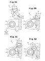
Figs. 3A to 3D are cross-sectional views taken along line 3-3 inFig. 1 , illustrating a process through which the ground clamp is attached to the steering apparatus; -
Fig. 4 is a cross-sectional view of the steering apparatus; and -
Fig. 5 is a cross-sectional view taken along line 3-3 inFig. 1 , illustrating a modification. - A steering apparatus according to one embodiment of the present invention will now be described with reference to
Figs. 1 to 4 . - As shown in
Figs. 1 and4 , asteering apparatus 10 includes asteering column 12, which rotationally supports asteering shaft 11. An electronic device such as a horn (not shown) is provided in thesteering column 12. - The
steering column 12 includes acolumn tube 21, which rotationally supports anupper shaft 13 of thesteering shaft 11, and apower assist unit 22, which applies assist force to alower shaft 14 of thesteering shaft 11. Thepower assist unit 22 includes a speed reducing mechanism, a motor, and an ECU. Thecolumn tube 21 and thepower assist unit 22 are accommodated in ahousing 23. Thehousing 23 is made of a conductive metal, and thecolumn tube 21 and thepower assist unit 22 are electrically connected to each other. Thesteering shaft 11, more specifically, thelower shaft 14 thereof, is coupled to an intermediate shaft via a universal joint (not shown). - The
housing 23 includes a gear housing portion, which accommodates the speed reducing mechanism. The gear housing portion has a pair ofsupport walls 24, which extends parallel with the axis of the steering shaft 11 (the lower shaft 14). As shown inFig. 1 , thesupport walls 24 are arranged to sandwich thelower shaft 14 when thesteering apparatus 10 is viewed from above. As shown inFig. 3A , thesupport walls 24 each have a throughhole 25 at the distal end. The throughholes 25 are aligned with each other. The throughholes 25 have the same inner diameter. The throughholes 25 receive a conductivetilt hinge shaft 26. As shown inFig. 1 , atilt hinge shaft 26 is fixed to aconductive fixing bracket 27, which extends from a vehicle body (not shown). A low-friction member made of a synthetic plastic is provided between thetilt hinge shaft 26 and thethrough hole 25, so that thetilt hinge shaft 26 and thesupport walls 24 are insulated from each other. Thesteering apparatus 10 can be tilted about thetilt hinge shaft 26. Aground clamp 30, which is formed of a conductive material and functions as a conductive member, is held between thetilt hinge shaft 26 and thehousing 23. - Next, the structure of the
ground clamp 30 will be described. - As shown in
Fig. 2 , theground clamp 30 is formed by bending an elastically deformable conductive metal plate. Theground clamp 30 includes a firstarcuate section 31, a secondarcuate section 32, which serves as a first contact section, adeformation section 33, afirst bent section 34, which serves as a second contact section, asecond bent section 35, and a folded-back section 36. - As shown in
Fig. 3D , the firstarcuate section 31 is arcuately curved to bulge toward thetilt hinge shaft 26. - The second
arcuate section 32 extends from the firstarcuate section 31 in a direction separated away from thelower shaft 14, and is curved to bulge toward thehousing 23. The secondarcuate section 32 is formed to extend along the outer circumferential surface of thetilt hinge shaft 26. The secondarcuate section 32 has threeprojections 37 on a surface that faces thetilt hinge shaft 26. Theprojections 37 project toward thetilt hinge shaft 26. The threeprojections 37 are arranged on the same arc. - The
deformation section 33 extends from an end of the secondarcuate section 32 that is located away from thelower shaft 14. Thedeformation section 33 has first to third smallarcuate sections 38 to 40 to be shaped as the numeral "3." The first smallarcuate section 38 extends from the secondarcuate section 32 and bulges away from thelower shaft 14. The second smallarcuate section 39 extends from the first smallarcuate section 38 and bulges toward thelower shaft 14. The third smallarcuate section 40 extends from the second smallarcuate section 39 and bulges away from thelower shaft 14. The second smallarcuate section 39 is located closer to thehousing 23 than the first smallarcuate section 38, and the third smallarcuate section 40 is located closer to thehousing 23 than the second smallarcuate section 39. - The first
bent section 34 extends from a part of thedeformation section 33 that is close to thehousing 23, that is, from the third smallarcuate section 40. The firstbent section 34 extends from an end of thedeformation section 33 and toward thelower shaft 14 and is bent at afirst apex 41 to be L-shaped. The distance between the firstbent section 34 and the secondarcuate section 32 decreases from thedeformation section 33 toward thefirst apex 41 1 and increases from thefirst apex 41 toward thelower shaft 14. That is, the firstbent section 34 is bent at thefirst apex 41 to protrude toward the secondarcuate section 32. As shown inFig. 3A , thefirst apex 41 is separated from the secondarcuate section 32 in a free state of the ground clamp, that is, a state of the ground clamp before being installed. - The second
bent section 35, which functions as an engaging portion, extends from a part of the firstbent section 34 that is close to the steeringshaft 11. The secondbent section 35 has an L shape, which is bent at asecond apex 42 and extends away from the secondarcuate section 32. The distance between the secondbent section 35 and the secondarcuate section 32 increases from the firstbent section 34 toward thesecond apex 42 and abruptly increases from thesecond apex 42 toward thelower shaft 14. That is, the secondbent section 35 is bent at thesecond apex 42 to protrude toward thelower shaft 14. - The folded-back
section 36 extends from a part of the secondbent section 35 that is away from the secondarcuate section 32, and is folded back toward thesecond apex 42. That is, the folded-backsection 36 is curved to bulge toward thehousing 23. - As shown in
Fig. 3A , a distance D1 to the secondarcuate section 32 from a straight line connecting the third smallarcuate section 40 and thesecond apex 42 of the secondbent section 35 is set to be slightly longer than a distance D0 between thetilt hinge shaft 26 and the housing 23 (D1 > D0) even when the secondarcuate section 32 and thefirst apex 41 contact each other. Also, a distance D2 between the firstarcuate section 31 and the folded-backsection 36 is set to be longer than the distance D1 to the secondarcuate section 32 from the straight line connecting the third smallarcuate section 40 and thesecond apex 42 of the second bent section 35 (D2 > D1 > D0). Further, a distance D3 between the first smallarcuate section 38 and the third smallarcuate section 40 is set to be longer than the distance D1 to the secondarcuate section 32 from the straight line connecting the third smallarcuate section 40 and thesecond apex 42 of the second bent section 35 (D3 > D1 > D0). - Next, a method for installing the
ground clamp 30 and operation of theground clamp 30 installed between thetilt hinge shaft 26 and thehousing 23 will be described. Theground clamp 30 is installed between thetilt hinge shaft 26 and thehousing 23 by being inserted toward the steeringshaft 11. - First, as shown in
Fig. 3A , theground clamp 30 is arranged at a position further away from the steeringshaft 11 than thetilt hinge shaft 26 and thehousing 23. - Next, as shown in
Fig. 3B , theentire ground clamp 30 is moved toward the steeringshaft 11 such that the folded-backsection 36 slides toward the steeringshaft 11 along the outer surface of thehousing 23 in an area between thehousing 23 and thetilt hinge shaft 26. Then, the distal end of the firstarcuate section 31 contacts thetilt hinge shaft 26. - Subsequently, as shown in
Fig. 3C , thedeformation section 33 is elastically deformed until thefirst apex 41 and the secondarcuate section 32 contact each other. Using as a fulcrum a part of the secondarcuate section 32 that contacts thefirst apex 41, the secondarcuate section 32 is elastically deformed such that the firstarcuate section 31 approaches the folded-backsection 36. Further, the firstbent section 34 is elastically deformed such that thesecond apex 42 is separated away from the third smallarcuate section 40. - The above described elastic deformations cause a distance D2x between the first
arcuate section 31 and thehousing 23 to be shorter than a distance D0 between thetilt hinge shaft 26 and the housing 23 (D2x < D0). This allows theground clamp 30 to move toward the steeringshaft 11. Since the firstarcuate section 31 is arcuately curved to bulge toward thetilt hinge shaft 26, the distal end thereof easily enters between thetilt hinge shaft 26 and thehousing 23. That is, theground clamp 30 can be easily inserted between thetilt hinge shaft 26 and thehousing 23. - When the folded-back
section 36 reaches a corner of thehousing 23 that is close to the steeringshaft 11 as shown inFig. 3D , the elastically deformed sections are slightly returned toward the original positions. Accordingly, the folded-backsection 36 is arranged between the steeringshaft 11 and a side of thehousing 23 that faces the steeringshaft 11, and the secondbent section 35 contacts a corner of thehousing 23 that is close to the steeringshaft 11. In this manner, the secondbent section 35 is hooked to the corner to restrict movement of theground clamp 30 away from the steeringshaft 11. - Also, using a part contacting the
first apex 41 as a fulcrum, the elastically deformed secondarcuate section 32 is returned to the original shape. Accordingly, the secondarcuate section 32 is pressed against the outer circumferential surface of thetilt hinge shaft 26 at a position between thetilt hinge shaft 26 and thehousing 23. The elastic deformations of thedeformation section 33 and the firstbent section 34 are maintained so that thefirst apex 41 and the secondarcuate section 32 are kept contacting each other. That is, theground clamp 30 receives an elastic restoring force that acts to separate thefirst apex 41 and the secondarcuate section 32 away from each other. This causes theground clamp 30 to be held between thetilt hinge shaft 26 and thehousing 23. Thefirst apex 41 and the secondarcuate section 32 are kept contacting each other as described above, which restricts elastic deformation of thedeformation section 33 that reduces the distance D3 between the first smallarcuate section 38 and the third smallarcuate section 40. That is, the distance D3 is prevented from being shorter than the distance D0 between thetilt hinge shaft 26 and thehousing 23. This restricts movement of theground clamp 30 toward the steeringshaft 11. - As shown in
Fig. 2 , the secondarcuate section 32, which contacts thetilt hinge shaft 26, has the threeprojections 37 projecting toward thetilt hinge shaft 26. The secondarcuate section 32 makes point-to-point contact with thetilt hinge shaft 26 at the three theprojections 37. It is known that point-to-point contact results in a higher contact pressure than surface-to-surface contact. In other words, theground clamp 30 and thetilt hinge shaft 26 contact each other with a sufficient pressure. Also, since a sufficiently high contact pressure between thetilt hinge shaft 26 and theprojections 37 is ensured, entry of foreign matter between thetilt hinge shaft 26 and theprojections 37 is restricted. - As described above, the above embodiment has the following advantages.
- (1) The
ground clamp 30 is inserted between thetilt hinge shaft 26 and thehousing 23 with thedeformation section 33 kept elastically deformed. Theground clamp 30 receives an elastic restoring force that acts to separate thefirst apex 41 and the secondarcuate section 32 away from each other. This causes theground clamp 30 to be held between thetilt hinge shaft 26 and thehousing 23. Therefore, for example, even if the distance between thetilt hinge shaft 26 and thehousing 23 is changed to some extent, theground clamp 30 can be held between thetilt hinge shaft 26 and thehousing 23. If the distance between thetilt hinge shaft 26 and thehousing 23 is changed to a great extent, the shape of thehousing 23 does not need to be changed, but only thedeformation section 33 of theground clamp 30 needs to be changed. In this manner, thesteering apparatus 10 can easily accommodate design changes. - (2) The
ground clamp 30 has the secondbent section 35, which is hooked to the corner of thehousing 23 that is close to the steeringshaft 11. This restricts movement of theground clamp 30 away from the steeringshaft 11. Accordingly, theground clamp 30 is prevented from unexpectedly falling off between thetilt hinge shaft 26 and thehousing 23. - (3) The
ground clamp 30, which is formed by a plate, includes the folded-backsection 36 at one end. The folded-backsection 36 extends from the end of the secondbent section 35 that is close to thehousing 23 and is folded back toward thesecond apex 42.
That is, the folded-backsection 36 is curved to bulge toward the steeringshaft 11. Since theground clamp 30 is inserted between thetilt hinge shaft 26 and thehousing 23 with the folded-backsection 36 leading, the folded-backsection 36 slides toward the steeringshaft 11 along the outer surface of thehousing 23. Therefore, the end of theground clamp 30 does not stick on thehousing 23. This allows an operator to smoothly install theground clamp 30. Also, fingers and the like of the operator are prevented from being caught by the ground clamp. - (4) When the
ground clamp 30 is inserted between thetilt hinge shaft 26 and thehousing 23, the secondarcuate section 32 and thefirst apex 41 contact each other. This prevents thedeformation section 33 from being deformed beyond the elastic limit and being plastically deformed. - (5) The second
arcuate section 32 has the threeprojections 37 projecting toward thetilt hinge shaft 26. Thus, when theground clamp 30 is inserted between thetilt hinge shaft 26 and thehousing 23, the threeprojections 37 make point-to-point contact with thetilt hinge shaft 26. Since point-to-point contact results in a higher contact pressure than surface-to-surface contact, foreign matter is unlikely to enter between theprojections 37 and thetilt hinge shaft 26. Therefore, for example, when rain water is splashed onto thesteering apparatus 10, rust is unlikely to form between theprojections 37 and thetilt hinge shaft 26. This prevents theprojections 37 and thetilt hinge shaft 26 from being separated from and non-conductive with each other. - The above embodiment may be modified as follows.
- In the above illustrated embodiment, the second
arcuate section 32 and thefirst apex 41 may be configured to contact each other at a position closer to the steeringshaft 11 than a line segment OA from the center O of thetilt hinge shaft 26 to thehousing 23 as shown inFig. 5 . On the line segment OA, the distance between thetilt hinge shaft 26 and thehousing 23 is the shortest (the minimum distance Dmin). That is, inFig. 5 , the secondarcuate section 32 and thefirst apex 41 preferably contact each other in an area defined by a line segment AOB. In this case, a distance between thehousing 23 and a part of the secondarcuate section 32 that contacts thefirst apex 41 is longer than the minimum distance Dmin between thetilt hinge shaft 26 and the housing 23 (Dx > Dmin). Therefore, even if the secondbent section 35 is disengaged from thehousing 23, theground clamp 30 is prevented from moving toward or away from the steeringshaft 11. Also, even if the secondarcuate section 32 is deformed toward thehousing 23 with a part contacting thefirst apex 41 serving as a fulcrum, theground clamp 30 is prevented from moving toward or away from the steeringshaft 11. That is, with the configuration of this modification, theground clamp 30 is more reliably held between thetilt hinge shaft 26 and thehousing 23 than the above illustrated embodiment. - When the
ground clamp 30 is held between thetilt hinge shaft 26 and thehousing 23 in the above illustrated embodiment, the secondarcuate section 32 and thefirst apex 41 do not necessarily need to contact each other. For example, the secondarcuate section 32 and thefirst apex 41 may contact each other only when the secondbent section 35 is disengaged from thehousing 23. In this case, the same advantages as the above illustrated embodiment are achieved. - In the above illustrated embodiment, the three
projections 37 are provided. However, if at least oneprojection 37 is provided, the same advantages as above are achieved. Theprojections 37 may be omitted. In the configuration without theprojections 37, theground clamp 30 is held between thetilt hinge shaft 26 and thehousing 23, conduction between thetilt hinge shaft 26 and thehousing 23 is ensured. - In the above illustrated embodiment, the second
arcuate section 32 and thefirst apex 41 do not necessarily need to contact each other. - In the above illustrated embodiment, the folded-back
section 36 may be omitted. - In the above illustrated embodiment, the folded-back
section 36 may be provided at an end of the firstarcuate section 31. - In the above illustrated embodiment, the second
bent section 35, which functions as an engaging portion, may be omitted. - In the illustrated embodiment, the second contact section is formed by the first
bent section 34, which includes thefirst apex 41. However, the second contact section does not necessary need to have thefirst apex 41. That is, the second contact section does not necessarily need to be bent. For example, the second contact section may be flat without being bent. Even in this case, the second contact section is allowed to contact thehousing 23. - In the above illustrated embodiment, the first contact section is formed by the arcuately curved second
arcuate section 32. However, the first contact section does not necessarily need to be curved arcuately. For example, the first contact section may be flat. Even in this case, the first contact section is allowed to contact thetilt hinge shaft 26. - In the above illustrated embodiment, the
deformation section 33 is shaped as numeral "3" having the first to third smallarcuate sections 38 to 40. However, thedeformation section 33 may have any shape as long as it can be elastically deformed to cause the first contact section and the second contact section to approach each other. - In the above illustrated embodiment, the first
arcuate section 31 may be omitted. Therefore, the present examples and embodiments are to be considered as illustrative and not restrictive and the invention is not to be limited to the details given herein, but may be modified within the scope and equivalence of the appended claims. - It is explicitly stated that all features disclosed in the description and/or the claims are intended to be disclosed separately and independently from each other for the purpose of original disclosure as well as for the purpose of restricting the claimed invention independent of the composition of the features in the embodiments and/or the claims. It is explicitly stated that all value ranges or indications of groups of entities disclose every possible intermediate value or intermediate entity for the purpose of original disclosure as well as for the purpose of restricting the claimed invention, in particular as limits of value ranges.
Claims (4)
- A steering apparatus (10) comprising:a steering shaft (11);a tilt hinge shaft (26) fixable to a vehicle body;a steering column (12) that rotationally supports the steering shaft (11); andan elastically deformable conductive member (30),wherein the steering apparatus (10) is tiltable about the tilt hinge shaft (26) and is electrically connectable to the vehicle body by installing the conductive member (30) between the tilt hinge shaft (26) and the steering column (12), the steering apparatus being characterized in thatthe conductive member (30) includes a first contact section (32) that contacts the tilt hinge shaft (26), a second contact section (34) that contacts the steering column (12), and a deformation section (33) that extends between the first contact section (32) and the second contact section (34), the deformation section (33) being elastically deformable such that the first contact section (32) and the second contact section (34) approach each other, andthe deformation section (33) is constructed to be inserted between the tilt hinge shaft (26) and the steering column (12), while being elastically deformed.
- The steering apparatus according to claim 1, characterized in that the conductive member (30) includes an engaging portion (35), which engages with the steering column (12) when moving away from between the tilt hinge shaft (26) and the steering column (12).
- The steering apparatus according to claim 1 or 2, characterized in that an end of at least one of the first contact section (32) and the second contact section (34) of the conductive member (30) is folded back away from at least one of the tilt hinge shaft (26) and the steering shaft (11) to form a folded-back section (36), and
the conductive member (30) is constructed to be inserted between the tilt hinge shaft (26) and the steering column (12) with the folded-back section (36) first. - The steering apparatus according to any one of claims 1 to 3, characterized in that, when the conductive member (30) is arranged between the tilt hinge shaft (26) and the steering column (12), the first contact section (32) and the second contact section (34) contact each other.
Applications Claiming Priority (1)
| Application Number | Priority Date | Filing Date | Title |
|---|---|---|---|
| JP2012206020A JP5978880B2 (en) | 2012-09-19 | 2012-09-19 | Steering device |
Publications (3)
| Publication Number | Publication Date |
|---|---|
| EP2711266A2 true EP2711266A2 (en) | 2014-03-26 |
| EP2711266A3 EP2711266A3 (en) | 2015-07-15 |
| EP2711266B1 EP2711266B1 (en) | 2018-08-22 |
Family
ID=49212635
Family Applications (1)
| Application Number | Title | Priority Date | Filing Date |
|---|---|---|---|
| EP13184670.1A Not-in-force EP2711266B1 (en) | 2012-09-19 | 2013-09-17 | Steering Apparatus |
Country Status (4)
| Country | Link |
|---|---|
| US (1) | US9079611B2 (en) |
| EP (1) | EP2711266B1 (en) |
| JP (1) | JP5978880B2 (en) |
| CN (1) | CN103661559B (en) |
Families Citing this family (3)
| Publication number | Priority date | Publication date | Assignee | Title |
|---|---|---|---|---|
| CN106458247B (en) * | 2014-06-13 | 2018-05-25 | 日本精工株式会社 | Steering device |
| JP6402617B2 (en) * | 2014-12-19 | 2018-10-10 | 株式会社ジェイテクト | Electric power steering device |
| DE102020204591A1 (en) | 2020-04-09 | 2021-10-14 | Thyssenkrupp Ag | Steering column for a motor vehicle |
Citations (1)
| Publication number | Priority date | Publication date | Assignee | Title |
|---|---|---|---|---|
| JP2010036734A (en) | 2008-08-05 | 2010-02-18 | Jtekt Corp | Steering device |
Family Cites Families (6)
| Publication number | Priority date | Publication date | Assignee | Title |
|---|---|---|---|---|
| JP3741549B2 (en) * | 1998-09-24 | 2006-02-01 | 光洋精工株式会社 | Steering device and fixture used therefor |
| JP2005067340A (en) * | 2003-08-22 | 2005-03-17 | Nsk Ltd | Steering column |
| JP5011801B2 (en) * | 2006-04-11 | 2012-08-29 | 日本精工株式会社 | Electric power steering device |
| JP2008207612A (en) * | 2007-02-23 | 2008-09-11 | Jtekt Corp | Electric power steering device |
| JP2008222050A (en) * | 2007-03-13 | 2008-09-25 | Jtekt Corp | Position adjustment type steering device |
| KR20120006163A (en) * | 2010-07-12 | 2012-01-18 | 주식회사 만도 | Tilt hinge bracket of steering wheel of automobile and steering column of automobile having same |
-
2012
- 2012-09-19 JP JP2012206020A patent/JP5978880B2/en not_active Expired - Fee Related
-
2013
- 2013-09-12 US US14/024,992 patent/US9079611B2/en not_active Expired - Fee Related
- 2013-09-17 CN CN201310424836.XA patent/CN103661559B/en not_active Expired - Fee Related
- 2013-09-17 EP EP13184670.1A patent/EP2711266B1/en not_active Not-in-force
Patent Citations (1)
| Publication number | Priority date | Publication date | Assignee | Title |
|---|---|---|---|---|
| JP2010036734A (en) | 2008-08-05 | 2010-02-18 | Jtekt Corp | Steering device |
Also Published As
| Publication number | Publication date |
|---|---|
| CN103661559A (en) | 2014-03-26 |
| US20140076093A1 (en) | 2014-03-20 |
| EP2711266B1 (en) | 2018-08-22 |
| CN103661559B (en) | 2017-04-12 |
| EP2711266A3 (en) | 2015-07-15 |
| US9079611B2 (en) | 2015-07-14 |
| JP2014058287A (en) | 2014-04-03 |
| JP5978880B2 (en) | 2016-08-24 |
Similar Documents
| Publication | Publication Date | Title |
|---|---|---|
| US9707910B2 (en) | Steering apparatus | |
| EP1437263A1 (en) | Fixing device for wire harness | |
| EP2711266B1 (en) | Steering Apparatus | |
| CN111869016B (en) | Plug connection and device for the electrical connection between an energy store and a drive unit | |
| JP5294004B2 (en) | Steering device | |
| US7150658B1 (en) | Terminal for an electrical connector | |
| US9669781B2 (en) | Steering apparatus | |
| EP3059139A1 (en) | Steering system | |
| US20080022477A1 (en) | Motor and wiper apparatus having the same | |
| US20020160666A1 (en) | Electrical contact | |
| CN114600442B (en) | Camera modules for vehicles | |
| CN107453142A (en) | Connector | |
| JP6778721B2 (en) | Connector for sun visor | |
| JPWO2015071930A1 (en) | Sun visor spring and sun visor support device | |
| KR102160150B1 (en) | Steering apparatus for vehicle | |
| JP2011230692A (en) | Shift lever device | |
| CN102576618B (en) | Micro Switch | |
| JP6131913B2 (en) | Wire harness fixing device and harness module | |
| CN117513920A (en) | opening and closing device | |
| JP6719941B2 (en) | Electronic component mounting member and imaging device | |
| CN116386934A (en) | Flat flexible electrical conductor and support device therefor | |
| JP4476777B2 (en) | Vehicle instrument | |
| US10333240B2 (en) | Connector assembly for electrically connecting circuit boards | |
| EP4542778A1 (en) | Connector and electronic device | |
| US12598719B2 (en) | Flexible printed circuit for a gearbox control unit of a commercial vehicle and corresponding gearbox control unit |
Legal Events
| Date | Code | Title | Description |
|---|---|---|---|
| PUAI | Public reference made under article 153(3) epc to a published international application that has entered the european phase |
Free format text: ORIGINAL CODE: 0009012 |
|
| AK | Designated contracting states |
Kind code of ref document: A2 Designated state(s): AL AT BE BG CH CY CZ DE DK EE ES FI FR GB GR HR HU IE IS IT LI LT LU LV MC MK MT NL NO PL PT RO RS SE SI SK SM TR |
|
| AX | Request for extension of the european patent |
Extension state: BA ME |
|
| PUAL | Search report despatched |
Free format text: ORIGINAL CODE: 0009013 |
|
| AK | Designated contracting states |
Kind code of ref document: A3 Designated state(s): AL AT BE BG CH CY CZ DE DK EE ES FI FR GB GR HR HU IE IS IT LI LT LU LV MC MK MT NL NO PL PT RO RS SE SI SK SM TR |
|
| AX | Request for extension of the european patent |
Extension state: BA ME |
|
| RIC1 | Information provided on ipc code assigned before grant |
Ipc: B62D 1/187 20060101AFI20150609BHEP Ipc: B62D 5/04 20060101ALI20150609BHEP Ipc: B60R 16/027 20060101ALI20150609BHEP Ipc: B62D 1/189 20060101ALI20150609BHEP |
|
| 17P | Request for examination filed |
Effective date: 20160113 |
|
| RBV | Designated contracting states (corrected) |
Designated state(s): AL AT BE BG CH CY CZ DE DK EE ES FI FR GB GR HR HU IE IS IT LI LT LU LV MC MK MT NL NO PL PT RO RS SE SI SK SM TR |
|
| 17Q | First examination report despatched |
Effective date: 20170306 |
|
| GRAP | Despatch of communication of intention to grant a patent |
Free format text: ORIGINAL CODE: EPIDOSNIGR1 |
|
| INTG | Intention to grant announced |
Effective date: 20180308 |
|
| GRAS | Grant fee paid |
Free format text: ORIGINAL CODE: EPIDOSNIGR3 |
|
| GRAA | (expected) grant |
Free format text: ORIGINAL CODE: 0009210 |
|
| AK | Designated contracting states |
Kind code of ref document: B1 Designated state(s): AL AT BE BG CH CY CZ DE DK EE ES FI FR GB GR HR HU IE IS IT LI LT LU LV MC MK MT NL NO PL PT RO RS SE SI SK SM TR |
|
| REG | Reference to a national code |
Ref country code: GB Ref legal event code: FG4D |
|
| REG | Reference to a national code |
Ref country code: CH Ref legal event code: EP |
|
| REG | Reference to a national code |
Ref country code: AT Ref legal event code: REF Ref document number: 1032118 Country of ref document: AT Kind code of ref document: T Effective date: 20180915 |
|
| REG | Reference to a national code |
Ref country code: IE Ref legal event code: FG4D |
|
| REG | Reference to a national code |
Ref country code: DE Ref legal event code: R096 Ref document number: 602013042293 Country of ref document: DE |
|
| REG | Reference to a national code |
Ref country code: FR Ref legal event code: PLFP Year of fee payment: 6 |
|
| PGFP | Annual fee paid to national office [announced via postgrant information from national office to epo] |
Ref country code: FR Payment date: 20180927 Year of fee payment: 6 Ref country code: DE Payment date: 20180905 Year of fee payment: 6 |
|
| REG | Reference to a national code |
Ref country code: NL Ref legal event code: MP Effective date: 20180822 |
|
| REG | Reference to a national code |
Ref country code: LT Ref legal event code: MG4D |
|
| PG25 | Lapsed in a contracting state [announced via postgrant information from national office to epo] |
Ref country code: SE Free format text: LAPSE BECAUSE OF FAILURE TO SUBMIT A TRANSLATION OF THE DESCRIPTION OR TO PAY THE FEE WITHIN THE PRESCRIBED TIME-LIMIT Effective date: 20180822 Ref country code: BG Free format text: LAPSE BECAUSE OF FAILURE TO SUBMIT A TRANSLATION OF THE DESCRIPTION OR TO PAY THE FEE WITHIN THE PRESCRIBED TIME-LIMIT Effective date: 20181122 Ref country code: NO Free format text: LAPSE BECAUSE OF FAILURE TO SUBMIT A TRANSLATION OF THE DESCRIPTION OR TO PAY THE FEE WITHIN THE PRESCRIBED TIME-LIMIT Effective date: 20181122 Ref country code: GR Free format text: LAPSE BECAUSE OF FAILURE TO SUBMIT A TRANSLATION OF THE DESCRIPTION OR TO PAY THE FEE WITHIN THE PRESCRIBED TIME-LIMIT Effective date: 20181123 Ref country code: IS Free format text: LAPSE BECAUSE OF FAILURE TO SUBMIT A TRANSLATION OF THE DESCRIPTION OR TO PAY THE FEE WITHIN THE PRESCRIBED TIME-LIMIT Effective date: 20181222 Ref country code: NL Free format text: LAPSE BECAUSE OF FAILURE TO SUBMIT A TRANSLATION OF THE DESCRIPTION OR TO PAY THE FEE WITHIN THE PRESCRIBED TIME-LIMIT Effective date: 20180822 Ref country code: LT Free format text: LAPSE BECAUSE OF FAILURE TO SUBMIT A TRANSLATION OF THE DESCRIPTION OR TO PAY THE FEE WITHIN THE PRESCRIBED TIME-LIMIT Effective date: 20180822 Ref country code: FI Free format text: LAPSE BECAUSE OF FAILURE TO SUBMIT A TRANSLATION OF THE DESCRIPTION OR TO PAY THE FEE WITHIN THE PRESCRIBED TIME-LIMIT Effective date: 20180822 Ref country code: RS Free format text: LAPSE BECAUSE OF FAILURE TO SUBMIT A TRANSLATION OF THE DESCRIPTION OR TO PAY THE FEE WITHIN THE PRESCRIBED TIME-LIMIT Effective date: 20180822 |
|
| REG | Reference to a national code |
Ref country code: AT Ref legal event code: MK05 Ref document number: 1032118 Country of ref document: AT Kind code of ref document: T Effective date: 20180822 |
|
| PG25 | Lapsed in a contracting state [announced via postgrant information from national office to epo] |
Ref country code: LV Free format text: LAPSE BECAUSE OF FAILURE TO SUBMIT A TRANSLATION OF THE DESCRIPTION OR TO PAY THE FEE WITHIN THE PRESCRIBED TIME-LIMIT Effective date: 20180822 Ref country code: AL Free format text: LAPSE BECAUSE OF FAILURE TO SUBMIT A TRANSLATION OF THE DESCRIPTION OR TO PAY THE FEE WITHIN THE PRESCRIBED TIME-LIMIT Effective date: 20180822 Ref country code: HR Free format text: LAPSE BECAUSE OF FAILURE TO SUBMIT A TRANSLATION OF THE DESCRIPTION OR TO PAY THE FEE WITHIN THE PRESCRIBED TIME-LIMIT Effective date: 20180822 |
|
| PG25 | Lapsed in a contracting state [announced via postgrant information from national office to epo] |
Ref country code: IT Free format text: LAPSE BECAUSE OF FAILURE TO SUBMIT A TRANSLATION OF THE DESCRIPTION OR TO PAY THE FEE WITHIN THE PRESCRIBED TIME-LIMIT Effective date: 20180822 Ref country code: RO Free format text: LAPSE BECAUSE OF FAILURE TO SUBMIT A TRANSLATION OF THE DESCRIPTION OR TO PAY THE FEE WITHIN THE PRESCRIBED TIME-LIMIT Effective date: 20180822 Ref country code: EE Free format text: LAPSE BECAUSE OF FAILURE TO SUBMIT A TRANSLATION OF THE DESCRIPTION OR TO PAY THE FEE WITHIN THE PRESCRIBED TIME-LIMIT Effective date: 20180822 Ref country code: AT Free format text: LAPSE BECAUSE OF FAILURE TO SUBMIT A TRANSLATION OF THE DESCRIPTION OR TO PAY THE FEE WITHIN THE PRESCRIBED TIME-LIMIT Effective date: 20180822 Ref country code: CZ Free format text: LAPSE BECAUSE OF FAILURE TO SUBMIT A TRANSLATION OF THE DESCRIPTION OR TO PAY THE FEE WITHIN THE PRESCRIBED TIME-LIMIT Effective date: 20180822 Ref country code: PL Free format text: LAPSE BECAUSE OF FAILURE TO SUBMIT A TRANSLATION OF THE DESCRIPTION OR TO PAY THE FEE WITHIN THE PRESCRIBED TIME-LIMIT Effective date: 20180822 Ref country code: ES Free format text: LAPSE BECAUSE OF FAILURE TO SUBMIT A TRANSLATION OF THE DESCRIPTION OR TO PAY THE FEE WITHIN THE PRESCRIBED TIME-LIMIT Effective date: 20180822 |
|
| REG | Reference to a national code |
Ref country code: CH Ref legal event code: PL |
|
| REG | Reference to a national code |
Ref country code: DE Ref legal event code: R097 Ref document number: 602013042293 Country of ref document: DE |
|
| PG25 | Lapsed in a contracting state [announced via postgrant information from national office to epo] |
Ref country code: DK Free format text: LAPSE BECAUSE OF FAILURE TO SUBMIT A TRANSLATION OF THE DESCRIPTION OR TO PAY THE FEE WITHIN THE PRESCRIBED TIME-LIMIT Effective date: 20180822 Ref country code: SM Free format text: LAPSE BECAUSE OF FAILURE TO SUBMIT A TRANSLATION OF THE DESCRIPTION OR TO PAY THE FEE WITHIN THE PRESCRIBED TIME-LIMIT Effective date: 20180822 Ref country code: SK Free format text: LAPSE BECAUSE OF FAILURE TO SUBMIT A TRANSLATION OF THE DESCRIPTION OR TO PAY THE FEE WITHIN THE PRESCRIBED TIME-LIMIT Effective date: 20180822 |
|
| REG | Reference to a national code |
Ref country code: BE Ref legal event code: MM Effective date: 20180930 |
|
| REG | Reference to a national code |
Ref country code: IE Ref legal event code: MM4A |
|
| PG25 | Lapsed in a contracting state [announced via postgrant information from national office to epo] |
Ref country code: LU Free format text: LAPSE BECAUSE OF NON-PAYMENT OF DUE FEES Effective date: 20180917 Ref country code: MC Free format text: LAPSE BECAUSE OF FAILURE TO SUBMIT A TRANSLATION OF THE DESCRIPTION OR TO PAY THE FEE WITHIN THE PRESCRIBED TIME-LIMIT Effective date: 20180822 |
|
| PLBE | No opposition filed within time limit |
Free format text: ORIGINAL CODE: 0009261 |
|
| STAA | Information on the status of an ep patent application or granted ep patent |
Free format text: STATUS: NO OPPOSITION FILED WITHIN TIME LIMIT |
|
| GBPC | Gb: european patent ceased through non-payment of renewal fee |
Effective date: 20181122 |
|
| 26N | No opposition filed |
Effective date: 20190523 |
|
| PG25 | Lapsed in a contracting state [announced via postgrant information from national office to epo] |
Ref country code: IE Free format text: LAPSE BECAUSE OF NON-PAYMENT OF DUE FEES Effective date: 20180917 |
|
| PG25 | Lapsed in a contracting state [announced via postgrant information from national office to epo] |
Ref country code: LI Free format text: LAPSE BECAUSE OF NON-PAYMENT OF DUE FEES Effective date: 20180930 Ref country code: CH Free format text: LAPSE BECAUSE OF NON-PAYMENT OF DUE FEES Effective date: 20180930 Ref country code: BE Free format text: LAPSE BECAUSE OF NON-PAYMENT OF DUE FEES Effective date: 20180930 Ref country code: SI Free format text: LAPSE BECAUSE OF FAILURE TO SUBMIT A TRANSLATION OF THE DESCRIPTION OR TO PAY THE FEE WITHIN THE PRESCRIBED TIME-LIMIT Effective date: 20180822 |
|
| PG25 | Lapsed in a contracting state [announced via postgrant information from national office to epo] |
Ref country code: GB Free format text: LAPSE BECAUSE OF NON-PAYMENT OF DUE FEES Effective date: 20181122 |
|
| PG25 | Lapsed in a contracting state [announced via postgrant information from national office to epo] |
Ref country code: MT Free format text: LAPSE BECAUSE OF NON-PAYMENT OF DUE FEES Effective date: 20180917 |
|
| PG25 | Lapsed in a contracting state [announced via postgrant information from national office to epo] |
Ref country code: TR Free format text: LAPSE BECAUSE OF FAILURE TO SUBMIT A TRANSLATION OF THE DESCRIPTION OR TO PAY THE FEE WITHIN THE PRESCRIBED TIME-LIMIT Effective date: 20180822 |
|
| REG | Reference to a national code |
Ref country code: DE Ref legal event code: R119 Ref document number: 602013042293 Country of ref document: DE |
|
| PG25 | Lapsed in a contracting state [announced via postgrant information from national office to epo] |
Ref country code: HU Free format text: LAPSE BECAUSE OF FAILURE TO SUBMIT A TRANSLATION OF THE DESCRIPTION OR TO PAY THE FEE WITHIN THE PRESCRIBED TIME-LIMIT; INVALID AB INITIO Effective date: 20130917 Ref country code: PT Free format text: LAPSE BECAUSE OF FAILURE TO SUBMIT A TRANSLATION OF THE DESCRIPTION OR TO PAY THE FEE WITHIN THE PRESCRIBED TIME-LIMIT Effective date: 20180822 |
|
| PG25 | Lapsed in a contracting state [announced via postgrant information from national office to epo] |
Ref country code: CY Free format text: LAPSE BECAUSE OF FAILURE TO SUBMIT A TRANSLATION OF THE DESCRIPTION OR TO PAY THE FEE WITHIN THE PRESCRIBED TIME-LIMIT Effective date: 20180822 Ref country code: MK Free format text: LAPSE BECAUSE OF NON-PAYMENT OF DUE FEES Effective date: 20180822 |
|
| PG25 | Lapsed in a contracting state [announced via postgrant information from national office to epo] |
Ref country code: DE Free format text: LAPSE BECAUSE OF NON-PAYMENT OF DUE FEES Effective date: 20200401 |
|
| PG25 | Lapsed in a contracting state [announced via postgrant information from national office to epo] |
Ref country code: FR Free format text: LAPSE BECAUSE OF NON-PAYMENT OF DUE FEES Effective date: 20190930 |