EP2711245A2 - Interior mirror display system - Google Patents
Interior mirror display system Download PDFInfo
- Publication number
- EP2711245A2 EP2711245A2 EP13185845.8A EP13185845A EP2711245A2 EP 2711245 A2 EP2711245 A2 EP 2711245A2 EP 13185845 A EP13185845 A EP 13185845A EP 2711245 A2 EP2711245 A2 EP 2711245A2
- Authority
- EP
- European Patent Office
- Prior art keywords
- camera
- room mirror
- display
- disposed
- vehicle
- Prior art date
- Legal status (The legal status is an assumption and is not a legal conclusion. Google has not performed a legal analysis and makes no representation as to the accuracy of the status listed.)
- Granted
Links
Images


Classifications
-
- B—PERFORMING OPERATIONS; TRANSPORTING
- B60—VEHICLES IN GENERAL
- B60R—VEHICLES, VEHICLE FITTINGS, OR VEHICLE PARTS, NOT OTHERWISE PROVIDED FOR
- B60R1/00—Optical viewing arrangements; Real-time viewing arrangements for drivers or passengers using optical image capturing systems, e.g. cameras or video systems specially adapted for use in or on vehicles
- B60R1/20—Real-time viewing arrangements for drivers or passengers using optical image capturing systems, e.g. cameras or video systems specially adapted for use in or on vehicles
- B60R1/22—Real-time viewing arrangements for drivers or passengers using optical image capturing systems, e.g. cameras or video systems specially adapted for use in or on vehicles for viewing an area outside the vehicle, e.g. the exterior of the vehicle
- B60R1/23—Real-time viewing arrangements for drivers or passengers using optical image capturing systems, e.g. cameras or video systems specially adapted for use in or on vehicles for viewing an area outside the vehicle, e.g. the exterior of the vehicle with a predetermined field of view
- B60R1/26—Real-time viewing arrangements for drivers or passengers using optical image capturing systems, e.g. cameras or video systems specially adapted for use in or on vehicles for viewing an area outside the vehicle, e.g. the exterior of the vehicle with a predetermined field of view to the rear of the vehicle
-
- B—PERFORMING OPERATIONS; TRANSPORTING
- B60—VEHICLES IN GENERAL
- B60R—VEHICLES, VEHICLE FITTINGS, OR VEHICLE PARTS, NOT OTHERWISE PROVIDED FOR
- B60R1/00—Optical viewing arrangements; Real-time viewing arrangements for drivers or passengers using optical image capturing systems, e.g. cameras or video systems specially adapted for use in or on vehicles
- B60R1/02—Rear-view mirror arrangements
- B60R1/06—Rear-view mirror arrangements mounted on vehicle exterior
-
- B—PERFORMING OPERATIONS; TRANSPORTING
- B60—VEHICLES IN GENERAL
- B60R—VEHICLES, VEHICLE FITTINGS, OR VEHICLE PARTS, NOT OTHERWISE PROVIDED FOR
- B60R1/00—Optical viewing arrangements; Real-time viewing arrangements for drivers or passengers using optical image capturing systems, e.g. cameras or video systems specially adapted for use in or on vehicles
- B60R1/02—Rear-view mirror arrangements
- B60R1/04—Rear-view mirror arrangements mounted inside vehicle
-
- B—PERFORMING OPERATIONS; TRANSPORTING
- B60—VEHICLES IN GENERAL
- B60R—VEHICLES, VEHICLE FITTINGS, OR VEHICLE PARTS, NOT OTHERWISE PROVIDED FOR
- B60R1/00—Optical viewing arrangements; Real-time viewing arrangements for drivers or passengers using optical image capturing systems, e.g. cameras or video systems specially adapted for use in or on vehicles
- B60R1/02—Rear-view mirror arrangements
- B60R1/08—Rear-view mirror arrangements involving special optical features, e.g. avoiding blind spots, e.g. convex mirrors; Side-by-side associations of rear-view and other mirrors
- B60R1/083—Anti-glare mirrors, e.g. "day-night" mirrors
- B60R1/088—Anti-glare mirrors, e.g. "day-night" mirrors using a cell of electrically changeable optical characteristic, e.g. liquid-crystal or electrochromic mirrors
-
- B—PERFORMING OPERATIONS; TRANSPORTING
- B60—VEHICLES IN GENERAL
- B60R—VEHICLES, VEHICLE FITTINGS, OR VEHICLE PARTS, NOT OTHERWISE PROVIDED FOR
- B60R1/00—Optical viewing arrangements; Real-time viewing arrangements for drivers or passengers using optical image capturing systems, e.g. cameras or video systems specially adapted for use in or on vehicles
- B60R1/20—Real-time viewing arrangements for drivers or passengers using optical image capturing systems, e.g. cameras or video systems specially adapted for use in or on vehicles
- B60R1/22—Real-time viewing arrangements for drivers or passengers using optical image capturing systems, e.g. cameras or video systems specially adapted for use in or on vehicles for viewing an area outside the vehicle, e.g. the exterior of the vehicle
- B60R1/28—Real-time viewing arrangements for drivers or passengers using optical image capturing systems, e.g. cameras or video systems specially adapted for use in or on vehicles for viewing an area outside the vehicle, e.g. the exterior of the vehicle with an adjustable field of view
-
- H—ELECTRICITY
- H04—ELECTRIC COMMUNICATION TECHNIQUE
- H04N—PICTORIAL COMMUNICATION, e.g. TELEVISION
- H04N7/00—Television systems
- H04N7/18—Closed-circuit television [CCTV] systems, i.e. systems in which the video signal is not broadcast
-
- B—PERFORMING OPERATIONS; TRANSPORTING
- B60—VEHICLES IN GENERAL
- B60R—VEHICLES, VEHICLE FITTINGS, OR VEHICLE PARTS, NOT OTHERWISE PROVIDED FOR
- B60R1/00—Optical viewing arrangements; Real-time viewing arrangements for drivers or passengers using optical image capturing systems, e.g. cameras or video systems specially adapted for use in or on vehicles
- B60R1/12—Mirror assemblies combined with other articles, e.g. clocks
- B60R2001/1215—Mirror assemblies combined with other articles, e.g. clocks with information displays
-
- B—PERFORMING OPERATIONS; TRANSPORTING
- B60—VEHICLES IN GENERAL
- B60R—VEHICLES, VEHICLE FITTINGS, OR VEHICLE PARTS, NOT OTHERWISE PROVIDED FOR
- B60R2300/00—Details of viewing arrangements using cameras and displays, specially adapted for use in a vehicle
- B60R2300/80—Details of viewing arrangements using cameras and displays, specially adapted for use in a vehicle characterised by the intended use of the viewing arrangement
- B60R2300/802—Details of viewing arrangements using cameras and displays, specially adapted for use in a vehicle characterised by the intended use of the viewing arrangement for monitoring and displaying vehicle exterior blind spot views
- B60R2300/8026—Details of viewing arrangements using cameras and displays, specially adapted for use in a vehicle characterised by the intended use of the viewing arrangement for monitoring and displaying vehicle exterior blind spot views in addition to a rear-view mirror system
Definitions
- Embodiments of the present invention relate to a room mirror for a vehicle, which can display external images.
- a conventional display system applied to a vehicle could ensure a driver to secure his or her field of vision for only the rear view of a vehicle.
- the driver confirms the situations of left and right rear views through a conventional side mirror, there is an inconvenience that the driver should turn his or her head to left and right sides to see the side mirror.
- the driver since the driver cannot keep eyes forward when turning his or her head, the driver is disturbed in safe driving. In particular, it is problematic that the driver cannot rapidly respond against lane changes, unexpected situations or defensive driving during high-speed running of the vehicle.
- the driver has difficulty in securing his or her field of vision because he or she is not able to see the side mirror due to water drops or dew condensation formed on a side window and the side mirror. It is also problematic that it is difficult for the driver to clearly recognize things through the side mirror due to side window tinting which has been recently performed.
- An aspect of the embodiments of the present invention provides a display room mirror system which is configured such that side rear view images of a vehicle are secured by cameras disposed at sides of the vehicle, and the secured side rear view images are displayed through a display module disposed in a room mirror so that a driver can minimize moving lines in his or her eyes during driving and can secure his or her field of vision in blind spots, thereby reducing the risk of an accident.
- a display room mirror system including: a camera module including a first camera and a second camera configured to capture left and right rear view images of a vehicle; a room mirror mounted in an inner part of a vehicle to detect a rear situation of the vehicle; and a display module disposed in the room mirror to output the images captured by the first camera and the second camera.
- An advantageous effect according to the embodiments of the present invention is that side rear images of the vehicle are obtained by the cameras disposed at the sides of the vehicle and are outputted from the display module disposed in the room mirror so that the driver can secure his or her field of vision for the side rear as well as the rear of the vehicle using only one room mirror disposed in the inner part of the vehicle without confirming the side mirror, thereby effectively reducing moving lines in the driver's field of vision.
- Another advantageous effect according to the embodiments of the present invention is that the images outputted from the display module by the power button unit and the image conversion button can be selectively used, and reflectance of the room mirror is changed using an oxidation and reduction reaction of an electrochromic device depending on the brightness of light by applying an electrochromic mirror to the room mirror so that the driver's glariness can be controlled.
- FIG. 1 is a block diagram illustrating the configuration of a display room mirror system according to an exemplary embodiment of the present invention
- FIG. 2 schematically illustrates a structure in which a first camera and a second camera are disposed in a vehicle according to another exemplary embodiment of the present invention
- FIG. 3 through FIG. 5 schematically illustrate a structure in which a display module is disposed on both sides of a room mirror, respectively, and a structure in which a power button unit is disposed, according to still another exemplary embodiment
- FIG. 6 and FIG. 7 schematically illustrate a structure in which a display module is disposed on a rear surface of the room mirror and a structure in which a power button unit is disposed, according to still another exemplary embodiment
- FIG. 8 illustrates the schematic structure of an electrochromic mirror according to still further another exemplary embodiment of the present invention.
- the gist of the embodiments of the present invention is to provide a display room mirror system which is configured such that side rear view images of a vehicle are obtained through cameras disposed at sides of a vehicle and are outputted from display modules disposed in a room mirror so that the function of a side mirror can be replaced by the room mirror, and thus the driver's field of vision for the side rear as well as the rear of the vehicle can be secured by only one room mirror disposed into the vehicle, thereby efficiently reducing moving lines in the driver's field of vision.
- FIG. 1 is a block diagram illustrating the configuration of a display room mirror system according to one exemplary embodiment of the present invention.
- a display room mirror system may be configured to include: a camera module 100 configured to capture side rear view images of a vehicle and adjust a capturing direction of a camera; a display module 200 configured to output the images obtained from the camera module 100; a power button unit 400 configured to turn on or off a power source of the display module 200; an image conversion button configured to selectively output the images of the display module; and a room mirror 300 detecting rear situations of the vehicle.
- the camera module 100 may include: a first camera 111 and a second camera 112 mounted on both sides of the vehicle to obtain side rear view images of the vehicle; and a camera control unit 130 adjusting a capturing direction of the first camera 111 and the second camera 112.
- the first camera 111 and the second camera 112 are disposed on both sides of the vehicle so as to capture the side rear view images of the vehicle. Furthermore, the first camera 111 and the second camera 112 may be disposed around left and right side mirrors of the vehicle, or may be disposed at the left and right side mirrors of the vehicle as shown in FIG. 2 . When the first camera 111 and the second camera 112 are disposed at the left and right side mirrors, they may be mounted to the outside of the left and right side mirrors or in the left and right side mirrors. As such, the side rear view images of the vehicle may be obtained by the first camera 111 and the second camera 112 disposed on external sides of the vehicle.
- the camera control unit 130 controls a capturing direction of the first camera 111 and the second camera 112.
- the capturing direction may be controlled by a driver.
- the capturing direction of the first camera 111 and the second camera 112 may be controlled depending on a steering angle of a handle.
- hand control by the driver and automatic control depending on a variation in the steering angle of the handle may be simultaneously performed.
- the camera control unit 130 may be implemented in a button or stick form as adjusting a mirror direction of the side mirrors. If a place enables the driver to easily operate the camera control unit during driving, the camera control unit may be disposed in any place of an inner part of the vehicle without a limitation.
- the camera control unit 130 When the camera control unit 130 automatically controls the first and second cameras 111, 112 depending on a variation in the steering angle of the handle for the vehicle, it may be implemented so as to control each direction of the first and second cameras 111, 112 by detecting the steering angle of the handle through a sensor. That is, when the steering angle of the handle is inputted to the left side, the capturing directions of the first and second cameras 111, 112 are moved to the left side depending on the steering angle so that the driving situations of a left rear view can be easily detected.
- the display room mirror system may further include a focusing unit performing zoom in and zoom out by changing a focusing distance of the first camera 111 and the second camera 112.
- the focusing unit may be implemented in a button or stick-like shape, and may change the focusing distance of a camera lens to be similar to controlling a direction of the side mirror.
- the display room mirror system may further include a separation judging unit that extracts information about a traffic lane from captured driving images and judges whether or not the vehicle gets out of the traffic lane based on the information; and a voice output unit that outputs a warning sound in order to inform the driver of lane departure.
- the display module 200 which is disposed in a room mirror 300, is a means that individually or selectively displays the images captured by the first camera 111 and the second camera 112.
- the display module 200 may be disposed at left and right sides of the room mirror 300 with the room mirror 300 as its center, respectively, or may be disposed on rear surfaces of the left and right sides of the room mirror 300, respectively. Alternately, one display module may be disposed on a rear surface of the room mirror.
- the display module 200 may be composed of an LCD, an OLED or the like.
- the left rear view images of the vehicle may be outputted through the display module located at a left side of the room mirror 300
- the right and rear view images of the vehicle may be outputted through the display module located at a right side of the room mirror 300 so that the driver can detect the side rear as well as the rear of the vehicle using only the room mirror 300 without observing the side mirror, and can reduce moving lines in his or her field of vision while driving.
- the display module 200 will be more specifically explained in the sections regarding FIG. 3 to FIG. 8 .
- the power button unit 400 turns on and off a power source of the display module 200.
- the power button unit 400 may be composed of a first button 411 and a second button 412.
- the side rear view images can be selectively confirmed. That is, when the display module 200 is entirely turned off, the side rear view images are not displayed on the room mirror 300, and the room mirror 300 performs only an original function of the room mirror 300.
- the display module 200 when the display module 200 is entirely turned on, the side rear view images are outputted from both sides of the room mirror 300, and the rear situations and side rear situations of the vehicle may be easily detected by only the room mirror 300. Furthermore, according to the driver's need, only one of the display modules located at the left and right sides of the room mirror 300 is turned on, thereby enabling the room mirror to be driven. A disposition structure of the power button unit 400 will be explained in more detail in the sections regarding FIG. 3 to FIG. 7 .
- An image conversion button 420 selectively outputs only one image among the images obtained from the first camera 111 and the second camera 112 or simultaneously dividedly outputs the images through the display module 200 disposed on the rear surface of the room mirror 300.
- the image conversion button 420 may be also applied to a case in which one display module 200 is disposed as well as the case in which the display modules 200 are disposed on the rear surfaces of the room mirror 300 to be spaced apart from each other.
- the first button 411 and the second button 412 perform similar functions to each other, in the case where one display module 220 is formed on the rear surface of the room mirror 300, it would be preferable to form the image conversion button 420.
- the image conversion button 420 may be formed at one side of the room mirror 300.
- the room mirror 300 which is a mirror mounted to enable a driver to secure his or her rear visual field in the inner part of the vehicle, may be composed of a half mirror having both properties of transmitting and reflecting light forward when the display module 200 is disposed on the rear surface of the room mirror 300.
- the driver is able to see information displayed in the display module 200 due to a transmission property of the half mirror.
- the half mirror is able to be used as a mirror due to a reflectance property of the half mirror.
- a configuration wherein the half mirror is formed in only a part corresponding to the display module 200, a configuration wherein the half mirror is mounted to the display module 200 itself, and the like could be embodied, and the configurations could be appropriately designed and changed by those having ordinary skill in the art in the relevant field.
- the room mirror 300 may be composed of an electrochromic mirror (ECM) which changes reflectance of the room mirror 300 so as to prevent a driver's glariness generated due to reflection of light resulting from a headlight of a rear vehicle. More specifically, the electrochromic mirror (ECM) changes the reflectance of the room mirror 300 using the redox reaction of an electro chromatic device depending on a difference in brightness of light measured by a sunlight sensor such as a photo diode measuring brightness of the front and the rear of the vehicle. Thus, the driver's glariness caused by the headlight of the rear vehicle can be controlled, thereby contributing to safe driving.
- ECM electrochromic mirror
- FIG. 2 schematically illustrates a structure in which a first camera and a second camera are disposed in a vehicle according to another exemplary embodiment of the present invention
- the first camera 111 and the second camera 112 may be mounted to a left side mirror 10 and a right side mirror 20 and may capture image for the side rear of the vehicle.
- the first camera 111 and the second camera 112 may be mounted to the left and right side mirrors 10, 20, may be mounted to the outside of the left and right side mirrors 10, 20 or may be embedded in the left and right side mirrors 10, 20.
- the first camera 111 and the second camera 112 may be mounted in any places of the sides of the vehicle.
- two cameras such as the first camera 111 and the second camera 112 are illustrated, it would be obvious that three or more cameras may be mounted.
- FIG. 3 through FIG. 5 schematically illustrate a structure in which a display module is disposed at both sides of a room mirror, respectively, and a structure in which a power button unit is disposed, according to still another exemplary embodiment.
- the room mirror 300 is disposed in the center, and the display modules are disposed on left and right sides of the room mirror 300 to be spaced apart from each other.
- the images captured by the first camera mounted to the side mirror on the left side of the vehicle or around the side mirror on the left side of the vehicle are displayed through the display module 200 disposed at the left side of the room mirror 300, and the images captured by the second camera mounted to the side mirror on the right side of the vehicle or around the side mirror on the right side of the vehicle are displayed through the display module 200 disposed at the right side of the room mirror 300.
- the rear situations of the vehicle may be detected through the room mirror 300 as a case of the conventional art.
- the driver may detect the side rear situations as well as the rear situations of the vehicle using only the room mirror 300 without observing the side mirror so that the driver can rapidly and correctly respond against lane changes or unexpected situations by efficiently reducing moving lines in the driver's field of vision, thereby enabling the driver to drive safely.
- the room mirror enables blind spots to be reduced, so that the driver can secure his or her wider field of vision.
- the power button unit 400 may be formed as shown in FIG. 4 or 5 .
- FIG. 4 only one power button unit 400 which simultaneously turns on and off the power sources of the display modules disposed to be spaced apart from each other with the room mirror 300 in its center may be used.
- the power button unit may be disposed at one end of a lower side of the room mirror 300.
- the power button unit may be at one side of the display module 200 as well as one end of an upper side of the room mirror 300.
- the disposition structure may be changed depending to the driver's convenience.
- the power button unit 400 may be composed of a first button 411 and a second button 412 so as to individually control power sources of the display modules disposed at the left and right sides of the room mirror 300.
- the first button 411 and the second button 412 may be formed at each of lower ends of the display modules 200 disposed to be spaced apart from each other.
- the first button 411 and the second button 412 may be disposed at each of upper ends or sides of the display module 200. The disposition structure thereof may be changed depending on the driver's convenience.
- FIG. 6 and FIG. 7 schematically illustrate a structure in which the display module is disposed at the rear surface of the room mirror, and a structure in which the power button unit is disposed, according to still another exemplary embodiment.
- the display module 200 is disposed on the rear surface of the room mirror 300 rather than being directly disposed on both sides of the room mirror 300.
- the display module 200 may be configured such that one display module 200 is disposed on the rear surface of the room mirror, or such that two display modules 200 are disposed at the left and right of the rear surface of the room mirror 300 to be separated from each other.
- the power button unit 400, the first button 411 and the second button 412 may be disposed in various locations such as the lower end of the room mirror, the lower end of the display module and the like depending to the driver's convenience as described above.
- the display room mirror system may further comprise an image conversion button that selectively outputs only one image among images obtained from the first camera and the second camera or dividedly outputs the images at the same time.
- the image conversion button may be disposed in various places such as a lower end of the room mirror 300 depending to the driver's convenience.
- the image conversion button may be integrated with the power button unit 400 and thus may have power control and image conversion functions as one button.
- the room mirror 300 may be composed of a half mirror having both properties of transmitting and reflecting light forward.
- the room mirror 300 enables the driver to see information displayed in the display module 200 due to the transmission property.
- the room mirror may be used as a mirror due to the reflectance property of the half mirror.
- this is only one example.
- a configuration in which the room mirror is formed in only a part corresponding to the display module 200 as the half mirror, a configuration in which the room mirror is mounted to the display module 200 itself as the half mirror, and the like may be embodied.
- the configurations may be appropriately designed and changed by those having ordinary skill in the art in the relevant field.
- the room mirror 300 may be composed of an electrochromic mirror (ECM) which changes reflectance of the room mirror 300 so as to prevent a driver's glariness generated due to the reflectance of light resulting from a headlight of a rear vehicle.
- ECM electrochromic mirror
- the electrochromic mirror may be composed of a transparent substrate and a transparent electrode and may display the images outputted from the display module 200 formed on the rear surface of the electrochromic mirror.
- FIG. 8 illustrates a schematic structure of a electrochromic mirror according to still further another exemplary embodiment.
- the electrochromic mirror (ECM) 300 is configured such that a first transparent substrate 310 and a second transparent substrate 320 facing each other are disposed to be spaced apart from each other, a transparent electrode 330 and a reflective layer 340 are formed on facing surfaces of the first and second transparent 310 and 320, respectively, a space is formed between the transparent electrode 330 and the reflective layer 340 using a sealant 350, and an electrochromic layer 360 is formed by injecting an electrochromic material and an electrolyte into the space formed as above.
- the electrochromic material capable of undergoing the reversible changes of optical properties by an electrochemical oxidation-reduction reaction is used for the electrochromic mirror 300.
- the electrochromic material does not have a color when an electrical signal is not applied from an external source, and then has a certain color when the electrical signal is applied, thereby controlling reflectivity of a room mirror 300.
- the transparent electrode 330 may be composed of indium doped tin oxide (ITO), antimony doped tin oxide (ATO), fluor doped tin oxide (FTO), indium doped zinc oxide (IZO), or the like.
- the electrochromic material may be an organic electrochromic material or an inorganic electrochromic material.
- the organic electrochromic material may be composed of viologen, anthraquinone, polyaniline, polypyrrole or polythiophene, and the inorganic electrochromic material may be WO 3, MoO 3, CeO 2, MnO 2 or Nb 2O5 .
- the electrochromic material is a material having an electrochromic characteristic in which light absorptivity is changed by the electrochemical oxidation-reduction reaction, and the electrochemical oxidation-reduction phenomenon of the electrochromic material is reversibly generated depending on whether or not a voltage is applied, and intensity of the voltage so that transmittancy and absorbance of the electrochromic material can be reversibly changed.
- a metal oxide electrochromic material containing tungsten, iridium, nickel and vanadium, an organic electrochromic material containing viologen and quinone, a conductive polymer electrochromic material containing polythiophene, polyaniline and polypyrrole, and a derivative thereof may be applied.
- the electrochromic material may be any one selected from the group consisting of polythiophene, polyaniline, polypyrrole, polyanthracene, polyfluorene, polycarbazole, polyphenylenevinylene, and a derivative thereof.
- the first substrate 310 and the second substrate 320 may be made of a transparent substrate such as a glass substrate.
- any one of the first substrate and the second substrate may be formed by applying a flexible transparent substrate rather than the transparent substrate such as the conventional glass substrate thereto. Thanks to the use of the flexible transparent film, a structure of the transparent film may be formed of an electrochromic material and an electrolyte using a coating (laminating) method rather than a vacuum bonding method, so that the efficiency of processes and a reduction in production cost can be realized, and an entire thickness and weight of the electrochromic mirror can be reduced, thereby enabling a degree of freedom in design to increase.
- the transparent film may be composed of any one of polyethylene terephthalate (PET), polycabonate (PC), an acrylonitrile-butadienestyrene copolymer (ABS), polymethyl methacrylate (PMMA), polyethylene naphthalate (PEN), polyether sulfone (PES), a cyclic olefin copolymer (COC), a triacetylcellulose (TAC) film, a polyvinyl alcohol (PVA) film, a polyimide (PI) film, and polystyrene (PS).
- PET polyethylene terephthalate
- PC polycabonate
- ABS acrylonitrile-butadienestyrene copolymer
- PMMA polymethyl methacrylate
- PEN polyethylene naphthalate
- PES polyether sulfone
- COC cyclic olefin copolymer
- TAC triacetylcellulose
- PVA polyvinyl alcohol
- the conductive reflection layer 340 may be formed on the second substrate 320 and may serve as a reflective plate reflecting incident light by passing through the electrochromic layer 160, and a counter electrode of the transparent electrode.
- the conductive reflection layer 340 may be made of at least one metal selected from the group consisting of Cu, Au, Ag, Ni, Al, Cr, Ru, Re, Pb, Sn, In, and Zn, or an alloy containing these metals. However, this is only an example, but is not limited.
- the electrochromic material layer of the electrochromic mirror may be in a liquid state or a solid state.
- the electrochromic material layer may include an electrolyte layer and an electrochromic coating layer formed on one surface of both surfaces of the electrolyte layer. That is, the electrochromic coating layer being in the solid state may be formed at both sides of the electrolyte layer being in the liquid state, or may be formed at only one side of the electrolyte layer.
- uniform discoloration is not performed, and in order to maintain an electrochromic state, a voltage should be continuously applied, thereby causing high power consumption.
- the electrochromatic coating layer when the electrochromatic coating layer is formed in the solid state, this enables uniform discoloration and decolorization to be realized. Also, since the electrochromic material has a memory effect, a voltage is applied only upon the discoloration and decolorization, and thus the electrochromic material consumes a small amount of power. Furhtermore, since a voltage is applied upon the decolorization, the speed of a decolorization reaction is fast, and since the electrochromic material to which a coating process is applied is an inorganic or organic polymer, durability of the device can be improved.
Landscapes
- Engineering & Computer Science (AREA)
- Multimedia (AREA)
- Mechanical Engineering (AREA)
- Chemical & Material Sciences (AREA)
- Crystallography & Structural Chemistry (AREA)
- Signal Processing (AREA)
- Rear-View Mirror Devices That Are Mounted On The Exterior Of The Vehicle (AREA)
- Electrochromic Elements, Electrophoresis, Or Variable Reflection Or Absorption Elements (AREA)
- Fittings On The Vehicle Exterior For Carrying Loads, And Devices For Holding Or Mounting Articles (AREA)
- Closed-Circuit Television Systems (AREA)
Abstract
Description
- Embodiments of the present invention relate to a room mirror for a vehicle, which can display external images.
- A conventional display system applied to a vehicle could ensure a driver to secure his or her field of vision for only the rear view of a vehicle. When the driver confirms the situations of left and right rear views through a conventional side mirror, there is an inconvenience that the driver should turn his or her head to left and right sides to see the side mirror. Also, since the driver cannot keep eyes forward when turning his or her head, the driver is disturbed in safe driving. In particular, it is problematic that the driver cannot rapidly respond against lane changes, unexpected situations or defensive driving during high-speed running of the vehicle.
- Furthermore, in case of bad weather such as rain, the driver has difficulty in securing his or her field of vision because he or she is not able to see the side mirror due to water drops or dew condensation formed on a side window and the side mirror. It is also problematic that it is difficult for the driver to clearly recognize things through the side mirror due to side window tinting which has been recently performed.
- Embodiments of the present invention have been made keeping in mind the above problems occurring in the related art. An aspect of the embodiments of the present invention provides a display room mirror system which is configured such that side rear view images of a vehicle are secured by cameras disposed at sides of the vehicle, and the secured side rear view images are displayed through a display module disposed in a room mirror so that a driver can minimize moving lines in his or her eyes during driving and can secure his or her field of vision in blind spots, thereby reducing the risk of an accident.
- According to an aspect of the embodiments of the present invention, there is provided a display room mirror system including: a camera module including a first camera and a second camera configured to capture left and right rear view images of a vehicle; a room mirror mounted in an inner part of a vehicle to detect a rear situation of the vehicle; and a display module disposed in the room mirror to output the images captured by the first camera and the second camera.
- An advantageous effect according to the embodiments of the present invention is that side rear images of the vehicle are obtained by the cameras disposed at the sides of the vehicle and are outputted from the display module disposed in the room mirror so that the driver can secure his or her field of vision for the side rear as well as the rear of the vehicle using only one room mirror disposed in the inner part of the vehicle without confirming the side mirror, thereby effectively reducing moving lines in the driver's field of vision.
- Also, another advantageous effect according to the embodiments of the present invention is that the images outputted from the display module by the power button unit and the image conversion button can be selectively used, and reflectance of the room mirror is changed using an oxidation and reduction reaction of an electrochromic device depending on the brightness of light by applying an electrochromic mirror to the room mirror so that the driver's glariness can be controlled.
- The accompanying drawings are included to provide a further understanding of the present invention, and are incorporated in and constitute a part of this specification. The drawings illustrate exemplary embodiments of the present invention and, together with the description, serve to explain principles of the present invention. In the drawings:
-
FIG. 1 is a block diagram illustrating the configuration of a display room mirror system according to an exemplary embodiment of the present invention; -
FIG. 2 schematically illustrates a structure in which a first camera and a second camera are disposed in a vehicle according to another exemplary embodiment of the present invention; -
FIG. 3 through FIG. 5 schematically illustrate a structure in which a display module is disposed on both sides of a room mirror, respectively, and a structure in which a power button unit is disposed, according to still another exemplary embodiment; -
FIG. 6 and FIG. 7 schematically illustrate a structure in which a display module is disposed on a rear surface of the room mirror and a structure in which a power button unit is disposed, according to still another exemplary embodiment; and -
FIG. 8 illustrates the schematic structure of an electrochromic mirror according to still further another exemplary embodiment of the present invention. - Exemplary embodiments according to the present invention will now be described more fully hereinafter with reference to the accompanying drawings. The exemplary embodiments of the present invention may, however, be embodied in many different forms and should not be construed as limited to the embodiments set forth herein. Rather these example embodiments are provided so that this disclosure will be thorough and complete, and will fully convey the scope of the invention to those skilled in the art. Furthermore, when it is determined that specific descriptions regarding publicly known relevant functions or configurations may unnecessarily be beside main points of the present invention, the corresponding descriptions are omitted. It will be further understood that terms used herein should be interpreted as having a meaning that is consistent with their meaning in the context of this specification. With regard to the elements which perform similar functions and operations, like numbers refer to like elements through the specification.
- The gist of the embodiments of the present invention is to provide a display room mirror system which is configured such that side rear view images of a vehicle are obtained through cameras disposed at sides of a vehicle and are outputted from display modules disposed in a room mirror so that the function of a side mirror can be replaced by the room mirror, and thus the driver's field of vision for the side rear as well as the rear of the vehicle can be secured by only one room mirror disposed into the vehicle, thereby efficiently reducing moving lines in the driver's field of vision.
-
FIG. 1 is a block diagram illustrating the configuration of a display room mirror system according to one exemplary embodiment of the present invention. - Referring to
FIG. 1 , a display room mirror system according to an exemplary embodiment of the present invention may be configured to include: acamera module 100 configured to capture side rear view images of a vehicle and adjust a capturing direction of a camera; adisplay module 200 configured to output the images obtained from thecamera module 100; apower button unit 400 configured to turn on or off a power source of thedisplay module 200; an image conversion button configured to selectively output the images of the display module; and aroom mirror 300 detecting rear situations of the vehicle. - The
camera module 100 may include: afirst camera 111 and asecond camera 112 mounted on both sides of the vehicle to obtain side rear view images of the vehicle; and acamera control unit 130 adjusting a capturing direction of thefirst camera 111 and thesecond camera 112. - The
first camera 111 and thesecond camera 112 are disposed on both sides of the vehicle so as to capture the side rear view images of the vehicle. Furthermore, thefirst camera 111 and thesecond camera 112 may be disposed around left and right side mirrors of the vehicle, or may be disposed at the left and right side mirrors of the vehicle as shown inFIG. 2 . When thefirst camera 111 and thesecond camera 112 are disposed at the left and right side mirrors, they may be mounted to the outside of the left and right side mirrors or in the left and right side mirrors. As such, the side rear view images of the vehicle may be obtained by thefirst camera 111 and thesecond camera 112 disposed on external sides of the vehicle. - The
camera control unit 130 controls a capturing direction of thefirst camera 111 and thesecond camera 112. The capturing direction may be controlled by a driver. Also, the capturing direction of thefirst camera 111 and thesecond camera 112 may be controlled depending on a steering angle of a handle. In addition, hand control by the driver and automatic control depending on a variation in the steering angle of the handle may be simultaneously performed. In the case of the hand control by the driver, thecamera control unit 130 may be implemented in a button or stick form as adjusting a mirror direction of the side mirrors. If a place enables the driver to easily operate the camera control unit during driving, the camera control unit may be disposed in any place of an inner part of the vehicle without a limitation. - When the
camera control unit 130 automatically controls the first andsecond cameras second cameras second cameras - Although it is not illustrated in the drawings, the display room mirror system according to the present embodiment of the invention may further include a focusing unit performing zoom in and zoom out by changing a focusing distance of the
first camera 111 and thesecond camera 112. The focusing unit may be implemented in a button or stick-like shape, and may change the focusing distance of a camera lens to be similar to controlling a direction of the side mirror. - Also, although it is not illustrated in the drawings, the display room mirror system according to the present embodiment of the invention may further include a separation judging unit that extracts information about a traffic lane from captured driving images and judges whether or not the vehicle gets out of the traffic lane based on the information; and a voice output unit that outputs a warning sound in order to inform the driver of lane departure.
- The
display module 200, which is disposed in aroom mirror 300, is a means that individually or selectively displays the images captured by thefirst camera 111 and thesecond camera 112. Thedisplay module 200 may be disposed at left and right sides of theroom mirror 300 with theroom mirror 300 as its center, respectively, or may be disposed on rear surfaces of the left and right sides of theroom mirror 300, respectively. Alternately, one display module may be disposed on a rear surface of the room mirror. Thedisplay module 200 may be composed of an LCD, an OLED or the like. As such, the left rear view images of the vehicle may be outputted through the display module located at a left side of theroom mirror 300, and the right and rear view images of the vehicle may be outputted through the display module located at a right side of theroom mirror 300 so that the driver can detect the side rear as well as the rear of the vehicle using only theroom mirror 300 without observing the side mirror, and can reduce moving lines in his or her field of vision while driving. Thedisplay module 200 will be more specifically explained in the sections regardingFIG. 3 to FIG. 8 . - The
power button unit 400 turns on and off a power source of thedisplay module 200. In the case of simultaneously or individually turning on and off thedisplay modules 200 disposed to be spaced apart from each other, thepower button unit 400 may be composed of afirst button 411 and asecond button 412. As such, as the output of thedisplay module 200 is controlled by thepower button unit 400, the side rear view images can be selectively confirmed. That is, when thedisplay module 200 is entirely turned off, the side rear view images are not displayed on theroom mirror 300, and theroom mirror 300 performs only an original function of theroom mirror 300. Also, when thedisplay module 200 is entirely turned on, the side rear view images are outputted from both sides of theroom mirror 300, and the rear situations and side rear situations of the vehicle may be easily detected by only theroom mirror 300. Furthermore, according to the driver's need, only one of the display modules located at the left and right sides of theroom mirror 300 is turned on, thereby enabling the room mirror to be driven. A disposition structure of thepower button unit 400 will be explained in more detail in the sections regardingFIG. 3 to FIG. 7 . - An
image conversion button 420 selectively outputs only one image among the images obtained from thefirst camera 111 and thesecond camera 112 or simultaneously dividedly outputs the images through thedisplay module 200 disposed on the rear surface of theroom mirror 300. At this time, theimage conversion button 420 may be also applied to a case in which onedisplay module 200 is disposed as well as the case in which thedisplay modules 200 are disposed on the rear surfaces of theroom mirror 300 to be spaced apart from each other. However, in the case in which thedisplay modules 200 are spaced apart from each other, since thefirst button 411 and thesecond button 412 perform similar functions to each other, in the case where one display module 220 is formed on the rear surface of theroom mirror 300, it would be preferable to form theimage conversion button 420. Theimage conversion button 420 may be formed at one side of theroom mirror 300. - The
room mirror 300, which is a mirror mounted to enable a driver to secure his or her rear visual field in the inner part of the vehicle, may be composed of a half mirror having both properties of transmitting and reflecting light forward when thedisplay module 200 is disposed on the rear surface of theroom mirror 300. As a result, when thedisplay module 200 operates, the driver is able to see information displayed in thedisplay module 200 due to a transmission property of the half mirror. When thedisplay module 200 does not operate, the half mirror is able to be used as a mirror due to a reflectance property of the half mirror. However, this is only one example. A configuration wherein the half mirror is formed in only a part corresponding to thedisplay module 200, a configuration wherein the half mirror is mounted to thedisplay module 200 itself, and the like could be embodied, and the configurations could be appropriately designed and changed by those having ordinary skill in the art in the relevant field. - Furthermore, the
room mirror 300 may be composed of an electrochromic mirror (ECM) which changes reflectance of theroom mirror 300 so as to prevent a driver's glariness generated due to reflection of light resulting from a headlight of a rear vehicle. More specifically, the electrochromic mirror (ECM) changes the reflectance of theroom mirror 300 using the redox reaction of an electro chromatic device depending on a difference in brightness of light measured by a sunlight sensor such as a photo diode measuring brightness of the front and the rear of the vehicle. Thus, the driver's glariness caused by the headlight of the rear vehicle can be controlled, thereby contributing to safe driving. A detailed structure of the electrochromic mirror will be explained in the sections below regardingFIG. 8 . -
FIG. 2 schematically illustrates a structure in which a first camera and a second camera are disposed in a vehicle according to another exemplary embodiment of the present invention; - Referring to
FIG. 2 , thefirst camera 111 and thesecond camera 112 may be mounted to aleft side mirror 10 and aright side mirror 20 and may capture image for the side rear of the vehicle. As shown in the drawing, thefirst camera 111 and thesecond camera 112 may be mounted to the left and right side mirrors 10, 20, may be mounted to the outside of the left and right side mirrors 10, 20 or may be embedded in the left and right side mirrors 10, 20. Furthermore, in a case where a place allows securing the side rear images even though they are not the places where the left and right side mirrors are located, thefirst camera 111 and thesecond camera 112 may be mounted in any places of the sides of the vehicle. In the drawing, although only two cameras such as thefirst camera 111 and thesecond camera 112 are illustrated, it would be obvious that three or more cameras may be mounted. -
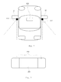
FIG. 3 through FIG. 5 schematically illustrate a structure in which a display module is disposed at both sides of a room mirror, respectively, and a structure in which a power button unit is disposed, according to still another exemplary embodiment. - Referring to
FIG. 3 to FIG. 5 , theroom mirror 300 is disposed in the center, and the display modules are disposed on left and right sides of theroom mirror 300 to be spaced apart from each other. The images captured by the first camera mounted to the side mirror on the left side of the vehicle or around the side mirror on the left side of the vehicle are displayed through thedisplay module 200 disposed at the left side of theroom mirror 300, and the images captured by the second camera mounted to the side mirror on the right side of the vehicle or around the side mirror on the right side of the vehicle are displayed through thedisplay module 200 disposed at the right side of theroom mirror 300. Furthermore, the rear situations of the vehicle may be detected through theroom mirror 300 as a case of the conventional art. Thanks to this, the driver may detect the side rear situations as well as the rear situations of the vehicle using only theroom mirror 300 without observing the side mirror so that the driver can rapidly and correctly respond against lane changes or unexpected situations by efficiently reducing moving lines in the driver's field of vision, thereby enabling the driver to drive safely. Furthermore, compared to the conventional side mirror, the room mirror enables blind spots to be reduced, so that the driver can secure his or her wider field of vision. - At this time, in order to selectively apply the side rear images displayed in the
display module 200, thepower button unit 400 may be formed as shown inFIG. 4 or 5 . InFIG. 4 , only onepower button unit 400 which simultaneously turns on and off the power sources of the display modules disposed to be spaced apart from each other with theroom mirror 300 in its center may be used. As shown in the drawings, with regard to a disposition structure thereof, the power button unit may be disposed at one end of a lower side of theroom mirror 300. However, this is only one example. The power button unit may be at one side of thedisplay module 200 as well as one end of an upper side of theroom mirror 300. The disposition structure may be changed depending to the driver's convenience. - Also, as shown in
FIG. 5 , thepower button unit 400 may be composed of afirst button 411 and asecond button 412 so as to individually control power sources of the display modules disposed at the left and right sides of theroom mirror 300. In this case, as shown in the drawing, thefirst button 411 and thesecond button 412 may be formed at each of lower ends of thedisplay modules 200 disposed to be spaced apart from each other. However, this is only one example. Also, thefirst button 411 and thesecond button 412 may be disposed at each of upper ends or sides of thedisplay module 200. The disposition structure thereof may be changed depending on the driver's convenience. -
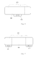
FIG. 6 and FIG. 7 schematically illustrate a structure in which the display module is disposed at the rear surface of the room mirror, and a structure in which the power button unit is disposed, according to still another exemplary embodiment. - A difference between the structures shown in
FIG. 3 to FIG. 5 and the structures shown inFIG. 6 and FIG. 7 is that thedisplay module 200 is disposed on the rear surface of theroom mirror 300 rather than being directly disposed on both sides of theroom mirror 300. At this time, thedisplay module 200 may be configured such that onedisplay module 200 is disposed on the rear surface of the room mirror, or such that twodisplay modules 200 are disposed at the left and right of the rear surface of theroom mirror 300 to be separated from each other. - As shown in
FIG. 6 and FIG. 7 , like the case ofFIG. 3 to FIG. 5 , thepower button unit 400, thefirst button 411 and thesecond button 412 may be disposed in various locations such as the lower end of the room mirror, the lower end of the display module and the like depending to the driver's convenience as described above. Furthermore, although it is not illustrated, the display room mirror system may further comprise an image conversion button that selectively outputs only one image among images obtained from the first camera and the second camera or dividedly outputs the images at the same time. With regard to a disposition location thereof, the image conversion button may be disposed in various places such as a lower end of theroom mirror 300 depending to the driver's convenience. Also, the image conversion button may be integrated with thepower button unit 400 and thus may have power control and image conversion functions as one button. - In this case, the
room mirror 300 may be composed of a half mirror having both properties of transmitting and reflecting light forward. Thus, when thedisplay module 200 operates, theroom mirror 300 enables the driver to see information displayed in thedisplay module 200 due to the transmission property. When thedisplay module 200 does not operate, the room mirror may be used as a mirror due to the reflectance property of the half mirror. However, this is only one example. In addition to this, a configuration in which the room mirror is formed in only a part corresponding to thedisplay module 200 as the half mirror, a configuration in which the room mirror is mounted to thedisplay module 200 itself as the half mirror, and the like may be embodied. The configurations may be appropriately designed and changed by those having ordinary skill in the art in the relevant field. - Also, the
room mirror 300 may be composed of an electrochromic mirror (ECM) which changes reflectance of theroom mirror 300 so as to prevent a driver's glariness generated due to the reflectance of light resulting from a headlight of a rear vehicle. The electrochromic mirror may be composed of a transparent substrate and a transparent electrode and may display the images outputted from thedisplay module 200 formed on the rear surface of the electrochromic mirror. -
FIG. 8 illustrates a schematic structure of a electrochromic mirror according to still further another exemplary embodiment. - Referring to
FIG. 8 , the electrochromic mirror (ECM) 300 is configured such that a firsttransparent substrate 310 and a secondtransparent substrate 320 facing each other are disposed to be spaced apart from each other, atransparent electrode 330 and areflective layer 340 are formed on facing surfaces of the first and second transparent 310 and 320, respectively, a space is formed between thetransparent electrode 330 and thereflective layer 340 using asealant 350, and anelectrochromic layer 360 is formed by injecting an electrochromic material and an electrolyte into the space formed as above. - The electrochromic material capable of undergoing the reversible changes of optical properties by an electrochemical oxidation-reduction reaction is used for the
electrochromic mirror 300. The electrochromic material does not have a color when an electrical signal is not applied from an external source, and then has a certain color when the electrical signal is applied, thereby controlling reflectivity of aroom mirror 300. - At this time, the
transparent electrode 330 may be composed of indium doped tin oxide (ITO), antimony doped tin oxide (ATO), fluor doped tin oxide (FTO), indium doped zinc oxide (IZO), or the like. The electrochromic material may be an organic electrochromic material or an inorganic electrochromic material. The organic electrochromic material may be composed of viologen, anthraquinone, polyaniline, polypyrrole or polythiophene, and the inorganic electrochromic material may be WO3, MoO3, CeO2, MnO2 or Nb2O5. Furthermore, the electrochromic material is a material having an electrochromic characteristic in which light absorptivity is changed by the electrochemical oxidation-reduction reaction, and the electrochemical oxidation-reduction phenomenon of the electrochromic material is reversibly generated depending on whether or not a voltage is applied, and intensity of the voltage so that transmittancy and absorbance of the electrochromic material can be reversibly changed. As the electrochromic material, a metal oxide electrochromic material containing tungsten, iridium, nickel and vanadium, an organic electrochromic material containing viologen and quinone, a conductive polymer electrochromic material containing polythiophene, polyaniline and polypyrrole, and a derivative thereof may be applied. Specifically, the electrochromic material may be any one selected from the group consisting of polythiophene, polyaniline, polypyrrole, polyanthracene, polyfluorene, polycarbazole, polyphenylenevinylene, and a derivative thereof. - Also, the
first substrate 310 and thesecond substrate 320 may be made of a transparent substrate such as a glass substrate. Alternately, as a different example from this, any one of the first substrate and the second substrate may be formed by applying a flexible transparent substrate rather than the transparent substrate such as the conventional glass substrate thereto. Thanks to the use of the flexible transparent film, a structure of the transparent film may be formed of an electrochromic material and an electrolyte using a coating (laminating) method rather than a vacuum bonding method, so that the efficiency of processes and a reduction in production cost can be realized, and an entire thickness and weight of the electrochromic mirror can be reduced, thereby enabling a degree of freedom in design to increase. The transparent film may be composed of any one of polyethylene terephthalate (PET), polycabonate (PC), an acrylonitrile-butadienestyrene copolymer (ABS), polymethyl methacrylate (PMMA), polyethylene naphthalate (PEN), polyether sulfone (PES), a cyclic olefin copolymer (COC), a triacetylcellulose (TAC) film, a polyvinyl alcohol (PVA) film, a polyimide (PI) film, and polystyrene (PS). - The
conductive reflection layer 340 may be formed on thesecond substrate 320 and may serve as a reflective plate reflecting incident light by passing through the electrochromic layer 160, and a counter electrode of the transparent electrode. Theconductive reflection layer 340 may be made of at least one metal selected from the group consisting of Cu, Au, Ag, Ni, Al, Cr, Ru, Re, Pb, Sn, In, and Zn, or an alloy containing these metals. However, this is only an example, but is not limited. - The electrochromic material layer of the electrochromic mirror may be in a liquid state or a solid state. When it is in a solid state, the electrochromic material layer may include an electrolyte layer and an electrochromic coating layer formed on one surface of both surfaces of the electrolyte layer. That is, the electrochromic coating layer being in the solid state may be formed at both sides of the electrolyte layer being in the liquid state, or may be formed at only one side of the electrolyte layer. When the electrochromic material layer is in the liquid state, uniform discoloration is not performed, and in order to maintain an electrochromic state, a voltage should be continuously applied, thereby causing high power consumption. However, as described above, when the electrochromatic coating layer is formed in the solid state, this enables uniform discoloration and decolorization to be realized. Also, since the electrochromic material has a memory effect, a voltage is applied only upon the discoloration and decolorization, and thus the electrochromic material consumes a small amount of power. Furhtermore, since a voltage is applied upon the decolorization, the speed of a decolorization reaction is fast, and since the electrochromic material to which a coating process is applied is an inorganic or organic polymer, durability of the device can be improved.
- As previously described, in the detailed description of the invention, having described the detailed exemplary embodiments of the invention, it should be apparent that modifications and variations can be made by persons skilled without deviating from the spirit or scope of the invention. Therefore, it is to be understood that the foregoing is illustrative of the present invention and is not to be construed as limited to the specific embodiments disclosed, and that modifications to the disclosed embodiments, as well as other embodiments, are intended to be included within the scope of the appended claims and their equivalents.
Claims (15)
- A display room mirror system, comprising:a camera module (100) configured to capture external images of a vehicle;a display module (200) configured to output images inputted from the camera module (100); anda room mirror (300) in which the display module (200) is received.
- The display room mirror system of claim 1, wherein the camera module (100) comprises a first camera (111) and a second camera (112) configured to capture left and right rear view images of the vehicle.
- The display room mirror system of claim 2, wherein the first camera (111) and the second camera (112) are mounted to left and right side mirrors of the vehicle, respectively.
- The display room mirror system of claim 2 or 3, wherein the camera module (100) further comprises a camera control unit (130) adjusting capturing directions of the first camera (111) and the second camera (112).
- The display room mirror system of claim 4, wherein the camera control unit (130) changes the capturing directions of the first camera (111) and the second camera (112) depending on a variation in steering angle of a handle for the vehicle.
- The display room mirror system of any one of claims 2 to 5, wherein the display module (200) is disposed on a rear surface of the room mirror (300), and individually outputs images inputted from the first camera (111) and the second camera (112).
- The display room mirror system of any one of claims 2 to 5, wherein the display module (200) is disposed at ends of left and right sides of the room mirror (300), respectively, and individually outputs images obtained from the first camera (111) and the second camera (112).
- The display room mirror system of any one of claims 2 to 5, wherein the display module (200) is disposed on the rear surface of the room mirror (300) and dividedly outputs the images obtained from the first camera (111) and the second camera (112).
- The display room mirror system of claim 8, further comprising: an image conversion button (420) that selectively outputs only one image among the images obtained from the first camera (111) and the second camera (112) or dividedly outputs the images at the same time.
- The display room mirror system of any one of claims 1 to 9, further comprising: a power button unit (400) that turns on or off a power source of the display module (200).
- The display room mirror system of claim 10, wherein the power button unit (400) is disposed at one side of the room mirror (300).
- The display room mirror system of claim 10, wherein the power button unit (400) is composed of a first button (411) and a second button (412) that individually turn on or off the power source of the display module (200).
- The display room mirror system of any one of claims 1 to 12, wherein the room mirror (300) comprises a half mirror.
- The display room mirror system of any one of claims 1 to 13, wherein the room mirror (300) comprises an electrochromic mirror.
- The display room mirror system of claim 14, wherein the electrochromic mirror comprises: a first substrate (310) and a second substrate (320) facing each other; an electrode (330) and a reflective layer (340) formed on facing surfaces of the first substrate (310) and the second substrate (320); and an electrochromic material layer disposed between the electrode (330) and the reflective layer (340).
Applications Claiming Priority (1)
| Application Number | Priority Date | Filing Date | Title |
|---|---|---|---|
| KR1020120106546A KR20140039820A (en) | 2012-09-25 | 2012-09-25 | Display room mirror system |
Publications (3)
| Publication Number | Publication Date |
|---|---|
| EP2711245A2 true EP2711245A2 (en) | 2014-03-26 |
| EP2711245A3 EP2711245A3 (en) | 2014-10-15 |
| EP2711245B1 EP2711245B1 (en) | 2016-12-28 |
Family
ID=49301294
Family Applications (1)
| Application Number | Title | Priority Date | Filing Date |
|---|---|---|---|
| EP13185845.8A Not-in-force EP2711245B1 (en) | 2012-09-25 | 2013-09-24 | Interior mirror display system |
Country Status (3)
| Country | Link |
|---|---|
| US (1) | US9756291B2 (en) |
| EP (1) | EP2711245B1 (en) |
| KR (1) | KR20140039820A (en) |
Cited By (2)
| Publication number | Priority date | Publication date | Assignee | Title |
|---|---|---|---|---|
| WO2015172703A1 (en) * | 2014-05-13 | 2015-11-19 | 汪玉华 | Combination device of camera and display screen |
| US10266125B2 (en) | 2014-05-13 | 2019-04-23 | Yuhua Wang | Camera device |
Families Citing this family (12)
| Publication number | Priority date | Publication date | Assignee | Title |
|---|---|---|---|---|
| DE102014105297A1 (en) | 2014-04-14 | 2015-10-15 | Connaught Electronics Ltd. | Method for detecting an object in a surrounding area of a motor vehicle by means of a camera system of the motor vehicle, camera system and motor vehicle |
| DE102014106035A1 (en) | 2014-04-30 | 2015-11-05 | Connaught Electronics Ltd. | Method for operating a driver assistance system with an electronic rearview mirror, driver assistance system and motor vehicle |
| CN105083134A (en) * | 2015-08-31 | 2015-11-25 | 黄维权 | Vehicle-mounted rearview mirror and automobile with same |
| CN105128747A (en) * | 2015-09-24 | 2015-12-09 | 惠州华阳通用电子有限公司 | Control method and device for interior mirror |
| US11228734B2 (en) * | 2017-03-10 | 2022-01-18 | The Hi-Tech Robotic Systemz Ltd | Single casing advanced driver assistance system |
| US11225267B2 (en) * | 2017-03-10 | 2022-01-18 | The Hi-Tech Robotic Systemz Ltd | Single casing advanced driver assistance system |
| JP6848779B2 (en) * | 2017-09-19 | 2021-03-24 | 株式会社デンソー | Electronic mirror system |
| CN110116678A (en) * | 2019-04-26 | 2019-08-13 | 惠州市德赛西威智能交通技术研究院有限公司 | A kind of switching rearview mirror shows control system, method and the automobile of content |
| EP3932740B1 (en) * | 2020-07-01 | 2022-10-19 | Alpine Electronics, Inc. | Electronic mirror system for use in a vehicle and vehicle comprising same |
| US11405559B1 (en) | 2021-02-19 | 2022-08-02 | Honda Motor Co., Ltd. | Systems and methods for live signal adjustment of a movable camera |
| KR102741745B1 (en) * | 2022-06-29 | 2024-12-12 | 최태규 | Rear image providing system and method capable of supporting rear image dual mode |
| KR102684526B1 (en) * | 2022-12-30 | 2024-07-12 | 주식회사 퓨전소프트 | Vehicle mirror automatic control system according to driver's gaze and head position change using 3d sensor |
Family Cites Families (44)
| Publication number | Priority date | Publication date | Assignee | Title |
|---|---|---|---|---|
| US6728375B1 (en) * | 1993-02-02 | 2004-04-27 | Anthony P. Palett | Mirror mounted mobile telephone system |
| US6498620B2 (en) * | 1993-02-26 | 2002-12-24 | Donnelly Corporation | Vision system for a vehicle including an image capture device and a display system having a long focal length |
| US5956181A (en) * | 1997-07-18 | 1999-09-21 | Lin; William | Two way mirror with dual functions of rear view mirror and video displayer |
| US6477464B2 (en) * | 2000-03-09 | 2002-11-05 | Donnelly Corporation | Complete mirror-based global-positioning system (GPS) navigation solution |
| US6420975B1 (en) * | 1999-08-25 | 2002-07-16 | Donnelly Corporation | Interior rearview mirror sound processing system |
| DE29818214U1 (en) * | 1998-10-12 | 2000-02-17 | Tuchscherer, Norbert, 60431 Frankfurt | Side view system for vehicles, in particular trucks |
| US6262831B1 (en) * | 1999-10-22 | 2001-07-17 | Gentex Corporation | Power supply for electrochromic mirrors in high voltage automotive power systems |
| US6411867B1 (en) * | 1999-10-27 | 2002-06-25 | Fujitsu Ten Limited | Vehicle driving support system, and steering angle detection device |
| WO2001064481A2 (en) * | 2000-03-02 | 2001-09-07 | Donnelly Corporation | Video mirror systems incorporating an accessory module |
| US7370983B2 (en) * | 2000-03-02 | 2008-05-13 | Donnelly Corporation | Interior mirror assembly with display |
| US6407468B1 (en) * | 2000-05-25 | 2002-06-18 | Gentex Corporation | Rearview mirror with buttons incorporating display |
| JP5629665B2 (en) * | 2000-11-06 | 2014-11-26 | 株式会社半導体エネルギー研究所 | vehicle |
| JP2002325250A (en) * | 2001-02-16 | 2002-11-08 | Ki Sun Kim | Video and audio recording device for vehicles |
| JP4270881B2 (en) * | 2001-05-28 | 2009-06-03 | 三菱電機株式会社 | Mobile device arrangement device |
| JP3854499B2 (en) * | 2001-12-03 | 2006-12-06 | 株式会社村上開明堂 | Rear mirror for camera built-in outer |
| JP2004082835A (en) * | 2002-08-26 | 2004-03-18 | Mitsubishi Electric Corp | In-vehicle display device |
| US6954152B1 (en) * | 2002-11-22 | 2005-10-11 | Matthews Frederick L | Side view mirror and camera assembly |
| JP2004247947A (en) * | 2003-02-13 | 2004-09-02 | Olympus Corp | Optical apparatus |
| JP3979330B2 (en) * | 2003-04-02 | 2007-09-19 | トヨタ自動車株式会社 | Image display device for vehicle |
| EP1637836A1 (en) * | 2003-05-29 | 2006-03-22 | Olympus Corporation | Device and method of supporting stereo camera, device and method of detecting calibration, and stereo camera system |
| US7502156B2 (en) * | 2004-07-12 | 2009-03-10 | Gentex Corporation | Variable reflectance mirrors and windows |
| CN101258052B (en) * | 2005-09-21 | 2010-08-18 | 三菱电机株式会社 | Display opening and closing angle detection mechanism |
| EP1969420A1 (en) * | 2006-01-05 | 2008-09-17 | TTE Technology, Inc. | System and method for creating a mirror effect in a liquid crystal display |
| JP4426535B2 (en) * | 2006-01-17 | 2010-03-03 | 本田技研工業株式会社 | Vehicle periphery monitoring device |
| WO2007092337A2 (en) * | 2006-02-02 | 2007-08-16 | Gentex Corporation | Power supply circuit for selectively supplying power to a vehicle a ccessory |
| US8274729B2 (en) * | 2006-03-03 | 2012-09-25 | Gentex Corporation | Thin-film coatings, electro-optic elements and assemblies incorporating these elements |
| JP4940767B2 (en) * | 2006-06-05 | 2012-05-30 | マツダ株式会社 | Vehicle surrounding information notification device |
| CN101479130B (en) * | 2006-06-28 | 2012-05-30 | 约翰逊控制技术公司 | Vehicle vision system |
| KR100775105B1 (en) * | 2006-09-06 | 2007-11-08 | 이동욱 | External monitoring system to secure the front line of sight for safe driving |
| JP5143009B2 (en) * | 2006-10-11 | 2013-02-13 | パナソニック株式会社 | Video display device and video display method |
| US20080211652A1 (en) * | 2007-03-02 | 2008-09-04 | Nanolumens Acquisition, Inc. | Dynamic Vehicle Display System |
| JP5088669B2 (en) * | 2007-03-23 | 2012-12-05 | 株式会社デンソー | Vehicle periphery monitoring device |
| JP5194679B2 (en) * | 2007-09-26 | 2013-05-08 | 日産自動車株式会社 | Vehicle periphery monitoring device and video display method |
| US8154418B2 (en) * | 2008-03-31 | 2012-04-10 | Magna Mirrors Of America, Inc. | Interior rearview mirror system |
| JP5112998B2 (en) * | 2008-09-16 | 2013-01-09 | 本田技研工業株式会社 | Vehicle perimeter monitoring device |
| US8465161B2 (en) * | 2008-10-14 | 2013-06-18 | Magna Mirrors Of America, Inc. | Interior rearview mirror assembly with button module |
| US8411245B2 (en) * | 2009-02-06 | 2013-04-02 | Gentex Corporation | Multi-display mirror system and method for expanded view around a vehicle |
| JP5286214B2 (en) * | 2009-09-30 | 2013-09-11 | 日立オートモティブシステムズ株式会社 | Vehicle control device |
| JP5742440B2 (en) * | 2010-05-13 | 2015-07-01 | 株式会社リコー | Electrochromic display element |
| US9264672B2 (en) * | 2010-12-22 | 2016-02-16 | Magna Mirrors Of America, Inc. | Vision display system for vehicle |
| KR101316433B1 (en) * | 2011-09-14 | 2013-10-08 | 현대자동차주식회사 | System for providing around information of vehicle and method thereof |
| KR20130057165A (en) * | 2011-11-23 | 2013-05-31 | 현대자동차주식회사 | Touch type display mirror |
| US9269263B2 (en) * | 2012-02-24 | 2016-02-23 | Magna Electronics Inc. | Vehicle top clearance alert system |
| JP6167525B2 (en) * | 2012-03-21 | 2017-07-26 | 株式会社リコー | Distance measuring device and vehicle |
-
2012
- 2012-09-25 KR KR1020120106546A patent/KR20140039820A/en not_active Withdrawn
-
2013
- 2013-09-24 EP EP13185845.8A patent/EP2711245B1/en not_active Not-in-force
- 2013-09-25 US US14/036,138 patent/US9756291B2/en active Active
Non-Patent Citations (1)
| Title |
|---|
| None |
Cited By (2)
| Publication number | Priority date | Publication date | Assignee | Title |
|---|---|---|---|---|
| WO2015172703A1 (en) * | 2014-05-13 | 2015-11-19 | 汪玉华 | Combination device of camera and display screen |
| US10266125B2 (en) | 2014-05-13 | 2019-04-23 | Yuhua Wang | Camera device |
Also Published As
| Publication number | Publication date |
|---|---|
| EP2711245B1 (en) | 2016-12-28 |
| KR20140039820A (en) | 2014-04-02 |
| US20140085471A1 (en) | 2014-03-27 |
| EP2711245A3 (en) | 2014-10-15 |
| US9756291B2 (en) | 2017-09-05 |
Similar Documents
| Publication | Publication Date | Title |
|---|---|---|
| EP2711245B1 (en) | Interior mirror display system | |
| US9494840B2 (en) | Electrochromic mirror and room mirror module for vehicle comprising the same | |
| US10315573B2 (en) | Method for displaying information to vehicle driver | |
| US9168870B2 (en) | Room mirror module for vehicle | |
| EP2713205B1 (en) | Electrochromic rear-view mirror including an OLED display | |
| US9052561B2 (en) | Electrochromic device | |
| US20190255919A1 (en) | Shading device for vehicle | |
| US20080278792A1 (en) | Electrochromic device having improved color properties | |
| CN107924084A (en) | Head-Up Display System | |
| US11511740B2 (en) | Movable carrier auxiliary system | |
| US11148510B2 (en) | Shading device | |
| US12044847B2 (en) | Movable carrier auxiliary system and vehicle auxiliary system | |
| KR102229531B1 (en) | Electrodeposition Element and Mirror Device | |
| JP6551930B2 (en) | Electronic mirror device, display control program and display control method | |
| US11766968B2 (en) | Vehicular interior rearview mirror assembly with video mirror display and VRLC stack | |
| CN113448115A (en) | Display device and control circuit | |
| US20140224966A1 (en) | Anti-glare mirror and method to vary reflectance thereof | |
| US11130447B2 (en) | Vehicle rear-view mirror and method for controlling the same, control system of the vehicle rear-view mirror | |
| US9778795B2 (en) | Touch apparatus | |
| KR102058002B1 (en) | Electrochromic module and method for controlling reflectance | |
| US20210155161A1 (en) | Electrochromic mirror module | |
| JP6255451B2 (en) | Display device | |
| JP2019214364A (en) | Sunshade apparatus | |
| CN210376957U (en) | Optical stack | |
| CN206870954U (en) | A kind of inside rear-view mirror and automobile |
Legal Events
| Date | Code | Title | Description |
|---|---|---|---|
| PUAI | Public reference made under article 153(3) epc to a published international application that has entered the european phase |
Free format text: ORIGINAL CODE: 0009012 |
|
| AK | Designated contracting states |
Kind code of ref document: A2 Designated state(s): AL AT BE BG CH CY CZ DE DK EE ES FI FR GB GR HR HU IE IS IT LI LT LU LV MC MK MT NL NO PL PT RO RS SE SI SK SM TR |
|
| AX | Request for extension of the european patent |
Extension state: BA ME |
|
| 17P | Request for examination filed |
Effective date: 20140327 |
|
| RBV | Designated contracting states (corrected) |
Designated state(s): AL AT BE BG CH CY CZ DE DK EE ES FI FR GB GR HR HU IE IS IT LI LT LU LV MC MK MT NL NO PL PT RO RS SE SI SK SM TR |
|
| PUAL | Search report despatched |
Free format text: ORIGINAL CODE: 0009013 |
|
| AK | Designated contracting states |
Kind code of ref document: A3 Designated state(s): AL AT BE BG CH CY CZ DE DK EE ES FI FR GB GR HR HU IE IS IT LI LT LU LV MC MK MT NL NO PL PT RO RS SE SI SK SM TR |
|
| AX | Request for extension of the european patent |
Extension state: BA ME |
|
| RIC1 | Information provided on ipc code assigned before grant |
Ipc: B60R 1/08 20060101AFI20140909BHEP |
|
| 17Q | First examination report despatched |
Effective date: 20151006 |
|
| GRAP | Despatch of communication of intention to grant a patent |
Free format text: ORIGINAL CODE: EPIDOSNIGR1 |
|
| INTG | Intention to grant announced |
Effective date: 20160802 |
|
| STAA | Information on the status of an ep patent application or granted ep patent |
Free format text: STATUS: GRANT OF PATENT IS INTENDED |
|
| GRAS | Grant fee paid |
Free format text: ORIGINAL CODE: EPIDOSNIGR3 |
|
| GRAA | (expected) grant |
Free format text: ORIGINAL CODE: 0009210 |
|
| STAA | Information on the status of an ep patent application or granted ep patent |
Free format text: STATUS: THE PATENT HAS BEEN GRANTED |
|
| AK | Designated contracting states |
Kind code of ref document: B1 Designated state(s): AL AT BE BG CH CY CZ DE DK EE ES FI FR GB GR HR HU IE IS IT LI LT LU LV MC MK MT NL NO PL PT RO RS SE SI SK SM TR |
|
| REG | Reference to a national code |
Ref country code: GB Ref legal event code: FG4D |
|
| REG | Reference to a national code |
Ref country code: CH Ref legal event code: EP |
|
| REG | Reference to a national code |
Ref country code: AT Ref legal event code: REF Ref document number: 856972 Country of ref document: AT Kind code of ref document: T Effective date: 20170115 |
|
| REG | Reference to a national code |
Ref country code: IE Ref legal event code: FG4D |
|
| REG | Reference to a national code |
Ref country code: DE Ref legal event code: R096 Ref document number: 602013015815 Country of ref document: DE |
|
| PG25 | Lapsed in a contracting state [announced via postgrant information from national office to epo] |
Ref country code: LV Free format text: LAPSE BECAUSE OF FAILURE TO SUBMIT A TRANSLATION OF THE DESCRIPTION OR TO PAY THE FEE WITHIN THE PRESCRIBED TIME-LIMIT Effective date: 20161228 |
|
| REG | Reference to a national code |
Ref country code: LT Ref legal event code: MG4D |
|
| PG25 | Lapsed in a contracting state [announced via postgrant information from national office to epo] |
Ref country code: SE Free format text: LAPSE BECAUSE OF FAILURE TO SUBMIT A TRANSLATION OF THE DESCRIPTION OR TO PAY THE FEE WITHIN THE PRESCRIBED TIME-LIMIT Effective date: 20161228 Ref country code: GR Free format text: LAPSE BECAUSE OF FAILURE TO SUBMIT A TRANSLATION OF THE DESCRIPTION OR TO PAY THE FEE WITHIN THE PRESCRIBED TIME-LIMIT Effective date: 20170329 Ref country code: NO Free format text: LAPSE BECAUSE OF FAILURE TO SUBMIT A TRANSLATION OF THE DESCRIPTION OR TO PAY THE FEE WITHIN THE PRESCRIBED TIME-LIMIT Effective date: 20170328 Ref country code: LT Free format text: LAPSE BECAUSE OF FAILURE TO SUBMIT A TRANSLATION OF THE DESCRIPTION OR TO PAY THE FEE WITHIN THE PRESCRIBED TIME-LIMIT Effective date: 20161228 |
|
| REG | Reference to a national code |
Ref country code: NL Ref legal event code: MP Effective date: 20161228 |
|
| REG | Reference to a national code |
Ref country code: AT Ref legal event code: MK05 Ref document number: 856972 Country of ref document: AT Kind code of ref document: T Effective date: 20161228 |
|
| RAP2 | Party data changed (patent owner data changed or rights of a patent transferred) |
Owner name: LG INNOTEK CO., LTD. |
|
| PG25 | Lapsed in a contracting state [announced via postgrant information from national office to epo] |
Ref country code: FI Free format text: LAPSE BECAUSE OF FAILURE TO SUBMIT A TRANSLATION OF THE DESCRIPTION OR TO PAY THE FEE WITHIN THE PRESCRIBED TIME-LIMIT Effective date: 20161228 Ref country code: RS Free format text: LAPSE BECAUSE OF FAILURE TO SUBMIT A TRANSLATION OF THE DESCRIPTION OR TO PAY THE FEE WITHIN THE PRESCRIBED TIME-LIMIT Effective date: 20161228 Ref country code: HR Free format text: LAPSE BECAUSE OF FAILURE TO SUBMIT A TRANSLATION OF THE DESCRIPTION OR TO PAY THE FEE WITHIN THE PRESCRIBED TIME-LIMIT Effective date: 20161228 |
|
| PG25 | Lapsed in a contracting state [announced via postgrant information from national office to epo] |
Ref country code: NL Free format text: LAPSE BECAUSE OF FAILURE TO SUBMIT A TRANSLATION OF THE DESCRIPTION OR TO PAY THE FEE WITHIN THE PRESCRIBED TIME-LIMIT Effective date: 20161228 |
|
| PG25 | Lapsed in a contracting state [announced via postgrant information from national office to epo] |
Ref country code: CZ Free format text: LAPSE BECAUSE OF FAILURE TO SUBMIT A TRANSLATION OF THE DESCRIPTION OR TO PAY THE FEE WITHIN THE PRESCRIBED TIME-LIMIT Effective date: 20161228 Ref country code: IS Free format text: LAPSE BECAUSE OF FAILURE TO SUBMIT A TRANSLATION OF THE DESCRIPTION OR TO PAY THE FEE WITHIN THE PRESCRIBED TIME-LIMIT Effective date: 20170428 Ref country code: EE Free format text: LAPSE BECAUSE OF FAILURE TO SUBMIT A TRANSLATION OF THE DESCRIPTION OR TO PAY THE FEE WITHIN THE PRESCRIBED TIME-LIMIT Effective date: 20161228 Ref country code: SK Free format text: LAPSE BECAUSE OF FAILURE TO SUBMIT A TRANSLATION OF THE DESCRIPTION OR TO PAY THE FEE WITHIN THE PRESCRIBED TIME-LIMIT Effective date: 20161228 Ref country code: RO Free format text: LAPSE BECAUSE OF FAILURE TO SUBMIT A TRANSLATION OF THE DESCRIPTION OR TO PAY THE FEE WITHIN THE PRESCRIBED TIME-LIMIT Effective date: 20161228 |
|
| PG25 | Lapsed in a contracting state [announced via postgrant information from national office to epo] |
Ref country code: PL Free format text: LAPSE BECAUSE OF FAILURE TO SUBMIT A TRANSLATION OF THE DESCRIPTION OR TO PAY THE FEE WITHIN THE PRESCRIBED TIME-LIMIT Effective date: 20161228 Ref country code: BG Free format text: LAPSE BECAUSE OF FAILURE TO SUBMIT A TRANSLATION OF THE DESCRIPTION OR TO PAY THE FEE WITHIN THE PRESCRIBED TIME-LIMIT Effective date: 20170328 Ref country code: SM Free format text: LAPSE BECAUSE OF FAILURE TO SUBMIT A TRANSLATION OF THE DESCRIPTION OR TO PAY THE FEE WITHIN THE PRESCRIBED TIME-LIMIT Effective date: 20161228 Ref country code: IT Free format text: LAPSE BECAUSE OF FAILURE TO SUBMIT A TRANSLATION OF THE DESCRIPTION OR TO PAY THE FEE WITHIN THE PRESCRIBED TIME-LIMIT Effective date: 20161228 Ref country code: ES Free format text: LAPSE BECAUSE OF FAILURE TO SUBMIT A TRANSLATION OF THE DESCRIPTION OR TO PAY THE FEE WITHIN THE PRESCRIBED TIME-LIMIT Effective date: 20161228 Ref country code: BE Free format text: LAPSE BECAUSE OF FAILURE TO SUBMIT A TRANSLATION OF THE DESCRIPTION OR TO PAY THE FEE WITHIN THE PRESCRIBED TIME-LIMIT Effective date: 20161228 Ref country code: PT Free format text: LAPSE BECAUSE OF FAILURE TO SUBMIT A TRANSLATION OF THE DESCRIPTION OR TO PAY THE FEE WITHIN THE PRESCRIBED TIME-LIMIT Effective date: 20170428 Ref country code: AT Free format text: LAPSE BECAUSE OF FAILURE TO SUBMIT A TRANSLATION OF THE DESCRIPTION OR TO PAY THE FEE WITHIN THE PRESCRIBED TIME-LIMIT Effective date: 20161228 |
|
| REG | Reference to a national code |
Ref country code: DE Ref legal event code: R097 Ref document number: 602013015815 Country of ref document: DE |
|
| PGFP | Annual fee paid to national office [announced via postgrant information from national office to epo] |
Ref country code: GB Payment date: 20170810 Year of fee payment: 5 Ref country code: DE Payment date: 20170810 Year of fee payment: 5 |
|
| PLBE | No opposition filed within time limit |
Free format text: ORIGINAL CODE: 0009261 |
|
| STAA | Information on the status of an ep patent application or granted ep patent |
Free format text: STATUS: NO OPPOSITION FILED WITHIN TIME LIMIT |
|
| PG25 | Lapsed in a contracting state [announced via postgrant information from national office to epo] |
Ref country code: DK Free format text: LAPSE BECAUSE OF FAILURE TO SUBMIT A TRANSLATION OF THE DESCRIPTION OR TO PAY THE FEE WITHIN THE PRESCRIBED TIME-LIMIT Effective date: 20161228 |
|
| 26N | No opposition filed |
Effective date: 20170929 |
|
| PG25 | Lapsed in a contracting state [announced via postgrant information from national office to epo] |
Ref country code: SI Free format text: LAPSE BECAUSE OF FAILURE TO SUBMIT A TRANSLATION OF THE DESCRIPTION OR TO PAY THE FEE WITHIN THE PRESCRIBED TIME-LIMIT Effective date: 20161228 |
|
| REG | Reference to a national code |
Ref country code: CH Ref legal event code: PL |
|
| PG25 | Lapsed in a contracting state [announced via postgrant information from national office to epo] |
Ref country code: MC Free format text: LAPSE BECAUSE OF FAILURE TO SUBMIT A TRANSLATION OF THE DESCRIPTION OR TO PAY THE FEE WITHIN THE PRESCRIBED TIME-LIMIT Effective date: 20161228 |
|
| REG | Reference to a national code |
Ref country code: IE Ref legal event code: MM4A |
|
| PG25 | Lapsed in a contracting state [announced via postgrant information from national office to epo] |
Ref country code: LU Free format text: LAPSE BECAUSE OF NON-PAYMENT OF DUE FEES Effective date: 20170924 |
|
| REG | Reference to a national code |
Ref country code: FR Ref legal event code: ST Effective date: 20180531 |
|
| PG25 | Lapsed in a contracting state [announced via postgrant information from national office to epo] |
Ref country code: LI Free format text: LAPSE BECAUSE OF NON-PAYMENT OF DUE FEES Effective date: 20170930 Ref country code: IE Free format text: LAPSE BECAUSE OF NON-PAYMENT OF DUE FEES Effective date: 20170924 Ref country code: CH Free format text: LAPSE BECAUSE OF NON-PAYMENT OF DUE FEES Effective date: 20170930 |
|
| PG25 | Lapsed in a contracting state [announced via postgrant information from national office to epo] |
Ref country code: FR Free format text: LAPSE BECAUSE OF NON-PAYMENT OF DUE FEES Effective date: 20171002 |
|
| PG25 | Lapsed in a contracting state [announced via postgrant information from national office to epo] |
Ref country code: MT Free format text: LAPSE BECAUSE OF NON-PAYMENT OF DUE FEES Effective date: 20170924 |
|
| REG | Reference to a national code |
Ref country code: DE Ref legal event code: R119 Ref document number: 602013015815 Country of ref document: DE |
|
| GBPC | Gb: european patent ceased through non-payment of renewal fee |
Effective date: 20180924 |
|
| PG25 | Lapsed in a contracting state [announced via postgrant information from national office to epo] |
Ref country code: HU Free format text: LAPSE BECAUSE OF FAILURE TO SUBMIT A TRANSLATION OF THE DESCRIPTION OR TO PAY THE FEE WITHIN THE PRESCRIBED TIME-LIMIT; INVALID AB INITIO Effective date: 20130924 |
|
| PG25 | Lapsed in a contracting state [announced via postgrant information from national office to epo] |
Ref country code: DE Free format text: LAPSE BECAUSE OF NON-PAYMENT OF DUE FEES Effective date: 20190402 |
|
| PG25 | Lapsed in a contracting state [announced via postgrant information from national office to epo] |
Ref country code: CY Free format text: LAPSE BECAUSE OF NON-PAYMENT OF DUE FEES Effective date: 20161228 Ref country code: GB Free format text: LAPSE BECAUSE OF NON-PAYMENT OF DUE FEES Effective date: 20180924 |
|
| PG25 | Lapsed in a contracting state [announced via postgrant information from national office to epo] |
Ref country code: MK Free format text: LAPSE BECAUSE OF FAILURE TO SUBMIT A TRANSLATION OF THE DESCRIPTION OR TO PAY THE FEE WITHIN THE PRESCRIBED TIME-LIMIT Effective date: 20161228 |
|
| PG25 | Lapsed in a contracting state [announced via postgrant information from national office to epo] |
Ref country code: TR Free format text: LAPSE BECAUSE OF FAILURE TO SUBMIT A TRANSLATION OF THE DESCRIPTION OR TO PAY THE FEE WITHIN THE PRESCRIBED TIME-LIMIT Effective date: 20161228 |
|
| PG25 | Lapsed in a contracting state [announced via postgrant information from national office to epo] |
Ref country code: AL Free format text: LAPSE BECAUSE OF FAILURE TO SUBMIT A TRANSLATION OF THE DESCRIPTION OR TO PAY THE FEE WITHIN THE PRESCRIBED TIME-LIMIT Effective date: 20161228 |