EP2711235A1 - Nonaqueous electrolyte secondary cell - Google Patents
Nonaqueous electrolyte secondary cell Download PDFInfo
- Publication number
- EP2711235A1 EP2711235A1 EP13184935.8A EP13184935A EP2711235A1 EP 2711235 A1 EP2711235 A1 EP 2711235A1 EP 13184935 A EP13184935 A EP 13184935A EP 2711235 A1 EP2711235 A1 EP 2711235A1
- Authority
- EP
- European Patent Office
- Prior art keywords
- secondary cell
- nonaqueous electrolyte
- electrolyte secondary
- case
- negative electrode
- Prior art date
- Legal status (The legal status is an assumption and is not a legal conclusion. Google has not performed a legal analysis and makes no representation as to the accuracy of the status listed.)
- Ceased
Links
- 239000011255 nonaqueous electrolyte Substances 0.000 title claims abstract description 54
- 239000008151 electrolyte solution Substances 0.000 claims abstract description 39
- 239000007788 liquid Substances 0.000 claims abstract description 24
- 230000015556 catabolic process Effects 0.000 abstract description 13
- 238000006731 degradation reaction Methods 0.000 abstract description 13
- 239000013585 weight reducing agent Substances 0.000 abstract description 8
- 239000007773 negative electrode material Substances 0.000 description 10
- 239000007774 positive electrode material Substances 0.000 description 10
- 238000012360 testing method Methods 0.000 description 6
- WHXSMMKQMYFTQS-UHFFFAOYSA-N Lithium Chemical compound [Li] WHXSMMKQMYFTQS-UHFFFAOYSA-N 0.000 description 5
- 229910052744 lithium Inorganic materials 0.000 description 5
- DHKHKXVYLBGOIT-UHFFFAOYSA-N 1,1-Diethoxyethane Chemical compound CCOC(C)OCC DHKHKXVYLBGOIT-UHFFFAOYSA-N 0.000 description 4
- RYGMFSIKBFXOCR-UHFFFAOYSA-N Copper Chemical compound [Cu] RYGMFSIKBFXOCR-UHFFFAOYSA-N 0.000 description 4
- KMTRUDSVKNLOMY-UHFFFAOYSA-N Ethylene carbonate Chemical compound O=C1OCCO1 KMTRUDSVKNLOMY-UHFFFAOYSA-N 0.000 description 4
- 229910052782 aluminium Inorganic materials 0.000 description 4
- XAGFODPZIPBFFR-UHFFFAOYSA-N aluminium Chemical compound [Al] XAGFODPZIPBFFR-UHFFFAOYSA-N 0.000 description 4
- 238000006243 chemical reaction Methods 0.000 description 4
- JBTWLSYIZRCDFO-UHFFFAOYSA-N ethyl methyl carbonate Chemical compound CCOC(=O)OC JBTWLSYIZRCDFO-UHFFFAOYSA-N 0.000 description 4
- 239000007769 metal material Substances 0.000 description 4
- YEJRWHAVMIAJKC-UHFFFAOYSA-N 4-Butyrolactone Chemical compound O=C1CCCO1 YEJRWHAVMIAJKC-UHFFFAOYSA-N 0.000 description 3
- IEJIGPNLZYLLBP-UHFFFAOYSA-N dimethyl carbonate Chemical compound COC(=O)OC IEJIGPNLZYLLBP-UHFFFAOYSA-N 0.000 description 3
- 229910021469 graphitizable carbon Inorganic materials 0.000 description 3
- 239000000463 material Substances 0.000 description 3
- 239000003960 organic solvent Substances 0.000 description 3
- -1 polyethylene Polymers 0.000 description 3
- 229910001290 LiPF6 Inorganic materials 0.000 description 2
- HBBGRARXTFLTSG-UHFFFAOYSA-N Lithium ion Chemical compound [Li+] HBBGRARXTFLTSG-UHFFFAOYSA-N 0.000 description 2
- 239000004698 Polyethylene Substances 0.000 description 2
- 239000011248 coating agent Substances 0.000 description 2
- 238000000576 coating method Methods 0.000 description 2
- 229910052802 copper Inorganic materials 0.000 description 2
- 239000010949 copper Substances 0.000 description 2
- 239000011889 copper foil Substances 0.000 description 2
- 238000003411 electrode reaction Methods 0.000 description 2
- 239000003792 electrolyte Substances 0.000 description 2
- 239000003759 ester based solvent Substances 0.000 description 2
- 238000011156 evaluation Methods 0.000 description 2
- 239000011888 foil Substances 0.000 description 2
- 229910001416 lithium ion Inorganic materials 0.000 description 2
- 238000005259 measurement Methods 0.000 description 2
- 238000000034 method Methods 0.000 description 2
- 229920000573 polyethylene Polymers 0.000 description 2
- RUOJZAUFBMNUDX-UHFFFAOYSA-N propylene carbonate Chemical compound CC1COC(=O)O1 RUOJZAUFBMNUDX-UHFFFAOYSA-N 0.000 description 2
- 229920006395 saturated elastomer Polymers 0.000 description 2
- 238000004804 winding Methods 0.000 description 2
- RNFJDJUURJAICM-UHFFFAOYSA-N 2,2,4,4,6,6-hexaphenoxy-1,3,5-triaza-2$l^{5},4$l^{5},6$l^{5}-triphosphacyclohexa-1,3,5-triene Chemical compound N=1P(OC=2C=CC=CC=2)(OC=2C=CC=CC=2)=NP(OC=2C=CC=CC=2)(OC=2C=CC=CC=2)=NP=1(OC=1C=CC=CC=1)OC1=CC=CC=C1 RNFJDJUURJAICM-UHFFFAOYSA-N 0.000 description 1
- 229910000838 Al alloy Inorganic materials 0.000 description 1
- OKTJSMMVPCPJKN-UHFFFAOYSA-N Carbon Chemical compound [C] OKTJSMMVPCPJKN-UHFFFAOYSA-N 0.000 description 1
- 229910000881 Cu alloy Inorganic materials 0.000 description 1
- 229910003005 LiNiO2 Inorganic materials 0.000 description 1
- 239000000654 additive Substances 0.000 description 1
- 229910003481 amorphous carbon Inorganic materials 0.000 description 1
- 239000003963 antioxidant agent Substances 0.000 description 1
- 230000003078 antioxidant effect Effects 0.000 description 1
- 239000003575 carbonaceous material Substances 0.000 description 1
- 239000002131 composite material Substances 0.000 description 1
- 238000013461 design Methods 0.000 description 1
- QHGJSLXSVXVKHZ-UHFFFAOYSA-N dilithium;dioxido(dioxo)manganese Chemical compound [Li+].[Li+].[O-][Mn]([O-])(=O)=O QHGJSLXSVXVKHZ-UHFFFAOYSA-N 0.000 description 1
- 230000005611 electricity Effects 0.000 description 1
- 239000004210 ether based solvent Substances 0.000 description 1
- 239000003063 flame retardant Substances 0.000 description 1
- 229910002804 graphite Inorganic materials 0.000 description 1
- 239000010439 graphite Substances 0.000 description 1
- 230000005484 gravity Effects 0.000 description 1
- 239000011810 insulating material Substances 0.000 description 1
- MHCFAGZWMAWTNR-UHFFFAOYSA-M lithium perchlorate Chemical compound [Li+].[O-]Cl(=O)(=O)=O MHCFAGZWMAWTNR-UHFFFAOYSA-M 0.000 description 1
- 229910003002 lithium salt Inorganic materials 0.000 description 1
- 159000000002 lithium salts Chemical class 0.000 description 1
- 238000004519 manufacturing process Methods 0.000 description 1
- 238000000691 measurement method Methods 0.000 description 1
- 239000012046 mixed solvent Substances 0.000 description 1
- 238000012986 modification Methods 0.000 description 1
- 230000004048 modification Effects 0.000 description 1
- 239000004014 plasticizer Substances 0.000 description 1
- 229920005672 polyolefin resin Polymers 0.000 description 1
- 239000011148 porous material Substances 0.000 description 1
- 230000002265 prevention Effects 0.000 description 1
- 239000000243 solution Substances 0.000 description 1
- 239000002904 solvent Substances 0.000 description 1
- 239000010935 stainless steel Substances 0.000 description 1
- 229910001220 stainless steel Inorganic materials 0.000 description 1
- 230000001629 suppression Effects 0.000 description 1
Images



Classifications
-
- H—ELECTRICITY
- H01—ELECTRIC ELEMENTS
- H01M—PROCESSES OR MEANS, e.g. BATTERIES, FOR THE DIRECT CONVERSION OF CHEMICAL ENERGY INTO ELECTRICAL ENERGY
- H01M10/00—Secondary cells; Manufacture thereof
- H01M10/05—Accumulators with non-aqueous electrolyte
-
- H—ELECTRICITY
- H01—ELECTRIC ELEMENTS
- H01M—PROCESSES OR MEANS, e.g. BATTERIES, FOR THE DIRECT CONVERSION OF CHEMICAL ENERGY INTO ELECTRICAL ENERGY
- H01M10/00—Secondary cells; Manufacture thereof
- H01M10/05—Accumulators with non-aqueous electrolyte
- H01M10/058—Construction or manufacture
- H01M10/0587—Construction or manufacture of accumulators having only wound construction elements, i.e. wound positive electrodes, wound negative electrodes and wound separators
-
- H—ELECTRICITY
- H01—ELECTRIC ELEMENTS
- H01M—PROCESSES OR MEANS, e.g. BATTERIES, FOR THE DIRECT CONVERSION OF CHEMICAL ENERGY INTO ELECTRICAL ENERGY
- H01M10/00—Secondary cells; Manufacture thereof
- H01M10/05—Accumulators with non-aqueous electrolyte
- H01M10/058—Construction or manufacture
-
- H—ELECTRICITY
- H01—ELECTRIC ELEMENTS
- H01M—PROCESSES OR MEANS, e.g. BATTERIES, FOR THE DIRECT CONVERSION OF CHEMICAL ENERGY INTO ELECTRICAL ENERGY
- H01M50/00—Constructional details or processes of manufacture of the non-active parts of electrochemical cells other than fuel cells, e.g. hybrid cells
- H01M50/40—Separators; Membranes; Diaphragms; Spacing elements inside cells
- H01M50/489—Separators, membranes, diaphragms or spacing elements inside the cells, characterised by their physical properties, e.g. swelling degree, hydrophilicity or shut down properties
-
- H—ELECTRICITY
- H01—ELECTRIC ELEMENTS
- H01M—PROCESSES OR MEANS, e.g. BATTERIES, FOR THE DIRECT CONVERSION OF CHEMICAL ENERGY INTO ELECTRICAL ENERGY
- H01M50/00—Constructional details or processes of manufacture of the non-active parts of electrochemical cells other than fuel cells, e.g. hybrid cells
- H01M50/60—Arrangements or processes for filling or topping-up with liquids; Arrangements or processes for draining liquids from casings
-
- B—PERFORMING OPERATIONS; TRANSPORTING
- B60—VEHICLES IN GENERAL
- B60L—PROPULSION OF ELECTRICALLY-PROPELLED VEHICLES; SUPPLYING ELECTRIC POWER FOR AUXILIARY EQUIPMENT OF ELECTRICALLY-PROPELLED VEHICLES; ELECTRODYNAMIC BRAKE SYSTEMS FOR VEHICLES IN GENERAL; MAGNETIC SUSPENSION OR LEVITATION FOR VEHICLES; MONITORING OPERATING VARIABLES OF ELECTRICALLY-PROPELLED VEHICLES; ELECTRIC SAFETY DEVICES FOR ELECTRICALLY-PROPELLED VEHICLES
- B60L50/00—Electric propulsion with power supplied within the vehicle
- B60L50/50—Electric propulsion with power supplied within the vehicle using propulsion power supplied by batteries or fuel cells
- B60L50/60—Electric propulsion with power supplied within the vehicle using propulsion power supplied by batteries or fuel cells using power supplied by batteries
- B60L50/64—Constructional details of batteries specially adapted for electric vehicles
-
- H—ELECTRICITY
- H01—ELECTRIC ELEMENTS
- H01M—PROCESSES OR MEANS, e.g. BATTERIES, FOR THE DIRECT CONVERSION OF CHEMICAL ENERGY INTO ELECTRICAL ENERGY
- H01M10/00—Secondary cells; Manufacture thereof
- H01M10/42—Methods or arrangements for servicing or maintenance of secondary cells or secondary half-cells
- H01M2010/4292—Aspects relating to capacity ratio of electrodes/electrolyte or anode/cathode
-
- H—ELECTRICITY
- H01—ELECTRIC ELEMENTS
- H01M—PROCESSES OR MEANS, e.g. BATTERIES, FOR THE DIRECT CONVERSION OF CHEMICAL ENERGY INTO ELECTRICAL ENERGY
- H01M2220/00—Batteries for particular applications
- H01M2220/20—Batteries in motive systems, e.g. vehicle, ship, plane
-
- Y—GENERAL TAGGING OF NEW TECHNOLOGICAL DEVELOPMENTS; GENERAL TAGGING OF CROSS-SECTIONAL TECHNOLOGIES SPANNING OVER SEVERAL SECTIONS OF THE IPC; TECHNICAL SUBJECTS COVERED BY FORMER USPC CROSS-REFERENCE ART COLLECTIONS [XRACs] AND DIGESTS
- Y02—TECHNOLOGIES OR APPLICATIONS FOR MITIGATION OR ADAPTATION AGAINST CLIMATE CHANGE
- Y02E—REDUCTION OF GREENHOUSE GAS [GHG] EMISSIONS, RELATED TO ENERGY GENERATION, TRANSMISSION OR DISTRIBUTION
- Y02E60/00—Enabling technologies; Technologies with a potential or indirect contribution to GHG emissions mitigation
- Y02E60/10—Energy storage using batteries
-
- Y—GENERAL TAGGING OF NEW TECHNOLOGICAL DEVELOPMENTS; GENERAL TAGGING OF CROSS-SECTIONAL TECHNOLOGIES SPANNING OVER SEVERAL SECTIONS OF THE IPC; TECHNICAL SUBJECTS COVERED BY FORMER USPC CROSS-REFERENCE ART COLLECTIONS [XRACs] AND DIGESTS
- Y02—TECHNOLOGIES OR APPLICATIONS FOR MITIGATION OR ADAPTATION AGAINST CLIMATE CHANGE
- Y02P—CLIMATE CHANGE MITIGATION TECHNOLOGIES IN THE PRODUCTION OR PROCESSING OF GOODS
- Y02P70/00—Climate change mitigation technologies in the production process for final industrial or consumer products
- Y02P70/50—Manufacturing or production processes characterised by the final manufactured product
-
- Y—GENERAL TAGGING OF NEW TECHNOLOGICAL DEVELOPMENTS; GENERAL TAGGING OF CROSS-SECTIONAL TECHNOLOGIES SPANNING OVER SEVERAL SECTIONS OF THE IPC; TECHNICAL SUBJECTS COVERED BY FORMER USPC CROSS-REFERENCE ART COLLECTIONS [XRACs] AND DIGESTS
- Y02—TECHNOLOGIES OR APPLICATIONS FOR MITIGATION OR ADAPTATION AGAINST CLIMATE CHANGE
- Y02T—CLIMATE CHANGE MITIGATION TECHNOLOGIES RELATED TO TRANSPORTATION
- Y02T10/00—Road transport of goods or passengers
- Y02T10/60—Other road transportation technologies with climate change mitigation effect
- Y02T10/70—Energy storage systems for electromobility, e.g. batteries
Definitions
- the present invention relates to a nonaqueous electrolyte secondary cell.
- Nonaqueous electrolyte secondary cell having a configuration in which an element including at least a positive electrode active material and a negative electrode active material is housed in a case.
- An example of the cell having such a configuration includes a lithium-ion battery cell mounted, for example, in a hybrid electric vehicle (HEV).
- the element is configured by at least a positive electrode plate carrying a positive electrode active material, a negative electrode plate carrying a negative electrode active material and a separator disposed between the positive electrode plate and the negative electrode plate.
- An electrolyte solution is poured into the case. The electrolyte solution is impregnated into the element.
- the amount of the electrolyte solution in the case is set in such a way that the amount of the electrolyte solution has a predetermined relation to the total pore volume of the element and the volume of the external and internal spaces of the element (see, Japanese Patent Application Laid-Open No. 2002-270225 ).
- the amount of the electrolyte solution set in this way enables the prevention of the shortage of electrolyte solution even when charge and discharge is repeated, and also enables the avoidance of the superfluous presence of the electrolyte solution in the case. As a result, it is possible to achieve high capacity and prevent leakage of the electrolyte solution.
- An object of the present invention is to provide a nonaqueous electrolyte secondary cell that is capable of suppressing the degradation of the input-output performance immediately after the repeated charge and discharge and also achieving weight reduction.
- a nonaqueous electrolyte secondary cell according to an aspect of the present invention includes: a case; an element housed in the case, the element including a positive electrode member, a negative electrode member and a separator; and an electrolyte solution poured into the case, wherein, in a direction perpendicular to a liquid surface of the electrolyte solution, the ratio calculated with the formula L2/L1 ⁇ 100 is 10% or more and 100% or less, where L1 represents a length between a first portion of the element, which is at a highest position, and a second portion of the element, which is at a lowest position, and L2 represents a length between the liquid surface and the second portion.
- a nonaqueous electrolyte secondary cell includes: a case; an element housed in the case, the element including a positive electrode member, a negative electrode member and a separator; and an electrolyte solution poured into the case.
- the ratio calculated with the formula L2/L1 ⁇ 100 is 10% or more and 100% or less, where L1 represents a length between a first portion of the element, which is at a highest position, and a second portion of the element, which is at a lowest position, and L2 represents a length between the liquid surface and the second portion.
- the length between the highest position and the lowest position of the element is represented by L1 and the length between the liquid surface and the lowest position is represented by L2, the ratio calculated with the formula L2/L1 ⁇ 100 is 10% or more and 100% or less.
- the length between the first portion and the second portion (that is, “the length between the highest position and the lowest position”)_means the length of the straight-line segment connecting, with the shortest distance, the plane parallel to the liquid surface, passing the highest portion of the element, and the plane parallel to the liquid surface, passing the lowest portion of the element.
- the “length between the liquid surface and the second portion” means the length of the straight-line segment connecting, with the shortest distance, the liquid surface and the plane parallel to the liquid surface, passing the lowest portion of the element.
- a nonaqueous electrolyte secondary cell having a ratio of 20% or more and 70% or less can be adopted.
- the ratio of 20% or more allows the electrolyte solution to be more certainly sucked up in the element, and hence the degradation of the input-output performance is more suppressed.
- the ratio of 70% or less allows the weight reduction to be more achieved.
- nonaqueous electrolyte secondary cell of the present embodiment a nonaqueous electrolyte secondary cell in which the air resistance of the separator is 100 seconds/100 cc or more can also be adopted.
- a nonaqueous electrolyte secondary cell which is charged and discharged at a large current can be adopted.
- the charge and discharge at a large current is performed at at least either of 50 A or more or 10 ItA or more. It is preferable that the charge and discharge at a large current be performed at at least either of 1000 A or less or 200ItA or less.
- a nonaqueous electrolyte secondary cell to be mounted in a hybrid electric vehicle can also be adopted.
- the nonaqueous electrolyte secondary cell 1 of the present embodiment includes a case 2, an element 10, and an electrolyte solution 20 (see FIG. 4 to FIG. 7 ).
- the element 10 is a power generating element, which is housed in the case 2 and includes a positive electrode member 11 and a negative electrode member 13.
- the electrolyte solution 20 is housed in the case 2 and the element 10 is immersed in the electrolyte solution 20 (see FIG. 4 to FIG. 7 ).
- the external terminals 21 pass through the opening of the external gasket 5 and the opening of the cover member 4.
- the external terminals 21 have projections projecting into the inside of the case body 3.
- a pouring port 6 for pouring the electrolyte solution 20 into the inside of the case body 3 is formed.
- the pouring port 6 is designed to be closed after the pouring of the electrolyte solution 20.
- the element 10 includes the positive electrode member 11, the negative electrode member 13 and the separator 15 disposed between these electrodes, and is formed by stacking them together and winding the stacked members.
- the positive electrode member 11 has a positive electrode current collector 11a made of, for example, aluminum foil and a positive electrode active material 11b.
- the positive electrode member 11 is formed in a sheet-like shape by applying a positive electrode active material 11b on the positive electrode current collector 11a.
- the negative electrode member 13 has a negative electrode current collector 13a made of, for example, copper foil and a negative electrode active material 13b.
- the negative electrode member 13 is formed in a sheet-like shape by applying a negative electrode active material 13b to the negative electrode current collector 13a.
- the nonaqueous electrolyte secondary cell 1 of the present embodiment has a pair of current collecting members 9 respectively electrically connected to the external terminals 21. Each of the current collecting members 9 is electrically connected to the positive electrode member 11 or the negative electrode member 13. Specifically, in the nonaqueous electrolyte secondary cell 1 of the present embodiment, as shown in FIG. 4 , on one end in the widthwise direction (direction C) of the element 10, the edge (the right side in FIG. 4 ) of the positive electrode member 11 (specifically, the positive electrode current collector 11a) projects more outside (right side) than the negative electrode member 13 and the separator 15. On the other hand, on the other end in the widthwise direction (direction C) of the element 10, the edge (the left side in FIG.
- the negative electrode current collector 13a projects more outside (the left side in FIG. 4 ) than the positive electrode member 11 and the separator 15.
- the protrusion of the positive electrode member 11 and the protrusion of the negative electrode member 13 are respectively and electrically connected to the current collecting members 9.
- each of the current collecting members 9 is not particularly limited, but is, for example, a plate-like shape.
- Each of the current collecting members 9 is welded to the protrusion of the corresponding external terminal 21 to be electrically connected to the corresponding external terminal 21.
- These current collecting members 9 are each formed of the same type of metal material as the metal material constituting the electrode member to which the corresponding current collecting member 9 is to be connected.
- Each of the external terminals 21 is designed to be electrically connected to, for example, external devices.
- the positive electrode active material 11b is a material capable of contributing in the positive electrode to the electrode reactions, namely, the charge reaction and the discharge reaction.
- Examples of such a positive electrode active material include lithium composite oxides such as lithium nickelate (LiNiO 2 ), lithium manganate (LiMnO 2 ) and lithium cobaltate (LiCoO 2 ).
- the negative electrode active material 13b is a material capable of contributing in the negative electrode to the electrode reactions, namely, the charge reaction and the discharge reaction.
- Examples of such a negative electrode active material include carbon-based materials such as amorphous carbon, hardly graphitizable carbon, easily graphitizable carbon and graphite.
- the separator 15 allows the passage of the electrolyte solution 20 while insulating the positive electrode 11 from negative electrode members 13.
- Examples of the separator 15 include porous films formed of polyolefin resins such as polyethylene. Such a porous film may contain additives such as a plasticizer, an antioxidant and a flame retardant.
- the air resistance of the separator 15 is a degree measured by the Gurley tester method in accordance with JIS P8117 of Japanese Industrial Standards (JIS).
- the electrolyte solution 20 is prepared by dissolving an electrolyte in an organic solvent.
- organic solvent include ester-based solvents such as propylene carbonate (PC), ethylene carbonate (EC), dimethyl carbonate (DMC) and ethyl methyl carbonate (EMC).
- organic solvent also include solvents prepared by mixing ether-based solvents such as ⁇ -butyrolactone ( ⁇ -BL) and diethoxyethane (DEE) with the ester-based solvents.
- Examples of the electrolyte include lithium salts such as lithium perchlorate (LiClO 4 ), lithium borofluoride (LiBF 4 ) and lithium hexafluorophosphate (LiPF 6 ).
- lithium salts such as lithium perchlorate (LiClO 4 ), lithium borofluoride (LiBF 4 ) and lithium hexafluorophosphate (LiPF 6 ).
- the element 10 is housed in the case body 3 in such a way that the widthwise direction (direction C) of each of the positive electrode member 11 and the negative electrode member 13 is parallel to the bottom face of the case body 3.
- the element 10 may be housed in the case body 3 in such a way that the widthwise direction of each of the positive electrode and negative electrode members 11 and 13 is parallel to the side wall of the case body 3.
- the electrolyte solution 20 is housed inside the case 2, and further, the element 10 is immersed in the electrolyte solution 20, and consequently, the positive electrode member 11, the negative electrode member 13 and the separator 15 are immersed in the electrolyte solution 20.
- P1 represents a position (height) of the highest portion of the element 10 in the vertical direction (the direction perpendicular to the liquid surface S of the electrolyte solution 20)
- P2 represents a position (height) of the lowest portion of the element 10.
- L1 represents the length between the position P1 and the position P2
- L2 represents the length between the liquid surface S and the position P2.
- the liquid surface S of the electrolyte solution 20 is kept horizontal by the gravity irrespective of the state of the case 2 being installed.
- the highest position P1 is the position of any of the positive electrode member 11, the negative electrode member 13 and the separator 15 in the vertical direction (the direction X in FIG. 5 to FIG. 7 ) which is positioned highest in the state of the case 2 being installed (see the position P1 in FIG. 5 to FIG. 7 ).
- the lowest position P2 is the position of any of the positive electrode member 11, the negative electrode member 13 and the separator 15 in the vertical direction (the direction X in FIG. 5 to FIG. 7 ) which is positioned lowest in the state of the case 2 being installed (see the position P2 in FIG. 5 to FIG.
- the length L1 is the length (see the length L1 in FIG. 5 to FIG. 7 ) in the vertical direction connecting the plane parallel to the liquid surface S passing the position P1 and the plane parallel to the liquid surface S passing the position P2 with the shortest distance.
- the length L2 is the length (see the length L2 in FIG. 5 to FIG. 7 ) in the vertical direction connecting the plane parallel to the liquid surface S passing through the position P2 and the liquid surface S with the shortest distance.
- the ratio of L2 to L1 of 10% or more allows the electrolyte solution 20 to be sucked up in the element 10 (mainly in the separators 15) up to the vicinity of the highest portions of the mutually facing portions of the positive electrode active material 11b and the negative electrode active material 13b. Hence the degradation of the input-output performance immediately after the repeated charge and discharge is suppressed.
- the ratio of 100% or less achieves the weight reduction. Accordingly, the ratio of 10% or more and 100% or less suppresses the degradation of the input-output performance immediately after the repeated charge and discharge and achieves the weight reduction.
- the mode having the ratio exceeding 100% means that the positive electrode active material 11b and the negative electrode active material 13b are all immersed so as to be lower than the liquid surface S of the electrolyte solution 20.
- the electrolyte solution 20 can be more certainly sucked up in the element 10 up to the vicinity of the highest portion of the element 10.
- the sucking up capability tends to be saturated, and the suppression capability of the degradation of the input-output performance tends to be saturated; and the sufficient achievement of the weight reduction also tends to be difficult.
- the ratio is more preferably 20% or more and 70% or less and furthermore preferably 30% or more and 40% or less.
- L1 and L2 are determined by a common measurement method. Specifically, L1 is determined by measuring the length of the gap between the inner surface of the case 2 and the element 10 by the X-ray CT analysis. Alternatively, L2 is determined by measuring the height of the liquid surface of the electrolyte solution by the X-ray CT analysis or ultrasonic measurement.
- the nonaqueous electrolyte secondary cell 1 of the present embodiment is preferably a lithium-ion battery cell.
- Such a nonaqueous electrolyte secondary cell is preferably mounted, for example, in hybrid electric vehicles (HEVs).
- HEVs hybrid electric vehicles
- the nonaqueous electrolyte secondary cell of the present invention is as described above, but the present invention is not limited to the foregoing embodiments and can be appropriately modified with respect to the design thereof within the intended scope of the present invention.
- the operational advantage of the present invention is also not limited to the foregoing embodiments.
- the embodiments disclosed herein should be construed in all respects as illustrative but not limiting.
- the scope of the present invention is not indicated by the foregoing description but by the scope of the claims.
- the scope of the present invention is intended to include all the modifications equivalent in the sense and the scope to the scope of the claims.
- a nonaqueous electrolyte secondary cell as shown in FIG. 1 to FIG. 4 was used.
- the positive electrode member was formed by coating an aluminum foil as the positive electrode current collector with lithium cobaltate as a positive electrode active material.
- the negative electrode member was formed by coating a copper foil as the negative electrode current collector with hardly graphitizable carbon as a negative electrode active material.
- a porous film formed of polyethylene was used as the separator.
- the air resistance (JIS P8117, Gurley tester method) of the separator was found to be 220 seconds/100 cc.
- An element was formed by stacking the positive electrode member, the negative electrode member and the separator on each other and winding them, and housed in the case.
- a nonaqueous electrolyte secondary cell (also referred to as the reference cell) having the foregoing ratio was also produced, which uses as the separator the separator being formed of the same material as described above and having an air resistance of 80 seconds/100 cc.
- This reference cell had a ratio of L2 to L1 being 0%.
- SOC is the abbreviation for State of Charge, which is the numerical value representing the charged state of a cell relative to the numerical value of the state of full charge defined to be 100%.
- ItA is a value representing a magnitude of the charge current or the discharge current, which is a value formed by attaching It and the unit of current to the multiple of the numerical value representing the nominal capacity of the cell.
- 1ItA is a current value when the quantity of electricity equivalent to the nominal capacity of the cell is charged or discharged for one hour.
- FIG. 8 shows the evaluation results of the output power performance of a cell.
- the ratio of L2 to L1 is 10% or more
- the degradation of the output performance is remarkably suppressed.
- the foregoing ratio is 20% or more, or alternatively 30% or more
- the degradation of the output performance is more suppressed.
- the air resistance of the separator is 100 seconds/100 cc or more
- the ratio (L2/L1 ⁇ 100) of 10% or more remarkably suppresses the degradation of the output performance of the cell.
Landscapes
- Chemical & Material Sciences (AREA)
- Chemical Kinetics & Catalysis (AREA)
- Electrochemistry (AREA)
- General Chemical & Material Sciences (AREA)
- Engineering & Computer Science (AREA)
- Manufacturing & Machinery (AREA)
- Secondary Cells (AREA)
Abstract
Description
- The present invention relates to a nonaqueous electrolyte secondary cell.
- There has hitherto been generally known a nonaqueous electrolyte secondary cell having a configuration in which an element including at least a positive electrode active material and a negative electrode active material is housed in a case. An example of the cell having such a configuration includes a lithium-ion battery cell mounted, for example, in a hybrid electric vehicle (HEV). The element is configured by at least a positive electrode plate carrying a positive electrode active material, a negative electrode plate carrying a negative electrode active material and a separator disposed between the positive electrode plate and the negative electrode plate. An electrolyte solution is poured into the case.
The electrolyte solution is impregnated into the element. - For such a type of nonaqueous electrolyte secondary cell, it is proposed that the amount of the electrolyte solution in the case is set in such a way that the amount of the electrolyte solution has a predetermined relation to the total pore volume of the element and the volume of the external and internal spaces of the element (see, Japanese Patent Application Laid-Open No.
2002-270225 - An object of the present invention is to provide a nonaqueous electrolyte secondary cell that is capable of suppressing the degradation of the input-output performance immediately after the repeated charge and discharge and also achieving weight reduction.
A nonaqueous electrolyte secondary cell according to an aspect of the present invention includes: a case; an element housed in the case, the element including a positive electrode member, a negative electrode member and a separator; and an electrolyte solution poured into the case, wherein, in a direction perpendicular to a liquid surface of the electrolyte solution, the ratio calculated with the formula L2/L1 × 100 is 10% or more and 100% or less, where L1 represents a length between a first portion of the element, which is at a highest position, and a second portion of the element, which is at a lowest position, and L2 represents a length between the liquid surface and the second portion. -
-
FIG. 1 is a schematic perspective view illustrating a nonaqueous electrolyte secondary cell of an embodiment of the present invention; -
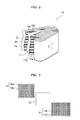
FIG. 2 is a schematic perspective view illustrating the element provided in the nonaqueous electrolyte secondary cell of the embodiment; -
FIG. 3 is a schematic plan view schematically illustrating a positive electrode member, a separator and a negative electrode member inFIG. 2 ; -
FIG. 4 is a schematic side view as viewed in the direction A ofFIG. 1 , schematically illustrating the internal structure of the nonaqueous electrolyte secondary cell of the embodiment; -
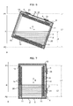
FIG. 5 is a view schematically illustrating the sectional view in the direction of the arrow BB inFIG. 1 ; -
FIG. 6 is a view schematically illustrating the sectional view in the direction of the arrow BB inFIG. 1 , showing the state of the nonaqueous electrolyte secondary cell being installed obliquely relative to the vertical direction from the state shown inFIG. 5 ; -
FIG. 7 is a view schematically illustrating the sectional view in the direction of the arrow BB inFIG. 1 , showing the state of the nonaqueous electrolyte secondary cell being installed as horizontally overturned by 90° from the state shown inFIG. 5 ; and -
FIG. 8 is a graph showing the relationship between the amount of the electrolyte solution and the output power performance. - A nonaqueous electrolyte secondary cell according to a present embodiment includes: a case; an element housed in the case, the element including a positive electrode member, a negative electrode member and a separator; and an electrolyte solution poured into the case. In a direction perpendicular to a liquid surface of the electrolyte solution, the ratio calculated with the formula L2/L1 × 100 is 10% or more and 100% or less, where L1 represents a length between a first portion of the element, which is at a highest position, and a second portion of the element, which is at a lowest position, and L2 represents a length between the liquid surface and the second portion.
That is, in the nonaqueous electrolyte secondary cell of the present embodiment, when in the state of the case being installed, in the direction perpendicular to the liquid surface of the electrolyte solution, the length between the highest position and the lowest position of the element is represented by L1 and the length between the liquid surface and the lowest position is represented by L2, the ratio calculated with the formula L2/L1 × 100 is 10% or more and 100% or less. - Here, "the length between the first portion and the second portion" (that is, "the length between the highest position and the lowest position")_means the length of the straight-line segment connecting, with the shortest distance, the plane parallel to the liquid surface, passing the highest portion of the element, and the plane parallel to the liquid surface, passing the lowest portion of the element. Also, the "length between the liquid surface and the second portion" means the length of the straight-line segment connecting, with the shortest distance, the liquid surface and the plane parallel to the liquid surface, passing the lowest portion of the element.
- According to the nonaqueous electrolyte secondary cell having such a configuration, the ratio of 10% or more allows the electrolyte solution to be sucked up in the element up to the vicinity of the uppermost portion in the mutually facing portions of the positive electrode active material and the negative electrode active material. Accordingly, the degradation of the input-output performance immediately after the repeated charge and discharge is suppressed. On the other hand, the ratio of 100% or less achieves weight reduction.
Consequently, according to the nonaqueous electrolyte secondary cell of the present embodiment, the degradation of the input-output performance immediately after the repeated charge and discharge is suppressed, and the weight reduction is also achieved. - As an aspect of the nonaqueous electrolyte secondary cell of the present embodiment, a nonaqueous electrolyte secondary cell having a ratio of 20% or more and 70% or less can be adopted.
According to the nonaqueous electrolyte secondary cell having such a configuration, the ratio of 20% or more allows the electrolyte solution to be more certainly sucked up in the element, and hence the degradation of the input-output performance is more suppressed.
Also, the ratio of 70% or less allows the weight reduction to be more achieved. - As another aspect of the nonaqueous electrolyte secondary cell of the present embodiment, a nonaqueous electrolyte secondary cell in which the air resistance of the separator is 100 seconds/100 cc or more can also be adopted.
- As yet another aspect of the nonaqueous electrolyte secondary cell of the present embodiment, a nonaqueous electrolyte secondary cell which is charged and discharged at a large current can be adopted.
The charge and discharge at a large current is performed at at least either of 50 A or more or 10 ItA or more. It is preferable that the charge and discharge at a large current be performed at at least either of 1000 A or less or 200ItA or less. - As a still yet another aspect of the nonaqueous electrolyte secondary cell of the present embodiment, a nonaqueous electrolyte secondary cell to be mounted in a hybrid electric vehicle can also be adopted.
- Hereinafter, an embodiment of the nonaqueous electrolyte secondary cell according to the present invention is described with reference to the accompanying drawings.
- As shown in
FIG. 1 to FIG. 4 , the nonaqueous electrolytesecondary cell 1 of the present embodiment includes acase 2, anelement 10, and an electrolyte solution 20 (seeFIG. 4 to FIG. 7 ). Theelement 10 is a power generating element, which is housed in thecase 2 and includes apositive electrode member 11 and anegative electrode member 13. Theelectrolyte solution 20 is housed in thecase 2 and theelement 10 is immersed in the electrolyte solution 20 (seeFIG. 4 to FIG. 7 ). - The
case 2 has acase body 3 having an opening opening toward one side and housing theelement 10, and acover member 4 covering the opening of thecase body 3.
Thecase body 3 and thecover member 4 are formed of, for example, a stainless steel plate, and are welded to each other.
In thecover member 4, two openings are formed. On the external surface of thecover member 4,external gaskets 5 being formed of an insulating material and having an opening formed therein are fitted.
The openings of theexternal gaskets 5 are located at the openings of thecover member 4, respectively. On the inside of the opening of each of theexternal gaskets 5, a part of anexternal terminal 21 is disposed. - The
external terminals 21 pass through the opening of theexternal gasket 5 and the opening of thecover member 4. Theexternal terminals 21 have projections projecting into the inside of thecase body 3. - The
external gaskets 5 and theexternal terminals 21 respectively include those for the positive electrode and the negative electrode. Theexternal gasket 5 and theexternal terminal 21 for the positive electrode are disposed on one end in the lengthwise direction of thecover member 4, and theexternal gasket 5 and theexternal terminal 21 for the negative electrode are disposed on the other end in the lengthwise direction of thecover member 4.
Theexternal terminal 21 for the positive electrode is formed of an aluminum-based metal material such as aluminum or an aluminum alloy. Theexternal terminal 21 for the negative electrode is formed of a copper-based metal material such as copper or a copper alloy. - In the
cover member 4, apouring port 6 for pouring theelectrolyte solution 20 into the inside of thecase body 3 is formed. Thepouring port 6 is designed to be closed after the pouring of theelectrolyte solution 20. - The
element 10 includes thepositive electrode member 11, thenegative electrode member 13 and theseparator 15 disposed between these electrodes, and is formed by stacking them together and winding the stacked members.
Thepositive electrode member 11 has a positive electrodecurrent collector 11a made of, for example, aluminum foil and a positive electrodeactive material 11b. Thepositive electrode member 11 is formed in a sheet-like shape by applying a positive electrodeactive material 11b on the positive electrodecurrent collector 11a.
Thenegative electrode member 13 has a negative electrodecurrent collector 13a made of, for example, copper foil and a negative electrodeactive material 13b. Thenegative electrode member 13 is formed in a sheet-like shape by applying a negative electrodeactive material 13b to the negative electrodecurrent collector 13a. - The nonaqueous electrolyte
secondary cell 1 of the present embodiment has a pair of current collectingmembers 9 respectively electrically connected to theexternal terminals 21. Each of thecurrent collecting members 9 is electrically connected to thepositive electrode member 11 or thenegative electrode member 13.
Specifically, in the nonaqueous electrolytesecondary cell 1 of the present embodiment, as shown inFIG. 4 , on one end in the widthwise direction (direction C) of theelement 10, the edge (the right side inFIG. 4 ) of the positive electrode member 11 (specifically, the positive electrodecurrent collector 11a) projects more outside (right side) than thenegative electrode member 13 and theseparator 15.
On the other hand, on the other end in the widthwise direction (direction C) of theelement 10, the edge (the left side inFIG. 4 ) of the negative electrode member 13 (specifically, the negative electrodecurrent collector 13a) projects more outside (the left side inFIG. 4 ) than thepositive electrode member 11 and theseparator 15.
The protrusion of thepositive electrode member 11 and the protrusion of thenegative electrode member 13 are respectively and electrically connected to thecurrent collecting members 9. - The shape of each of the
current collecting members 9 is not particularly limited, but is, for example, a plate-like shape. Each of thecurrent collecting members 9 is welded to the protrusion of the correspondingexternal terminal 21 to be electrically connected to the correspondingexternal terminal 21.
Thesecurrent collecting members 9 are each formed of the same type of metal material as the metal material constituting the electrode member to which the corresponding current collectingmember 9 is to be connected. Each of theexternal terminals 21 is designed to be electrically connected to, for example, external devices. - The positive electrode
active material 11b is a material capable of contributing in the positive electrode to the electrode reactions, namely, the charge reaction and the discharge reaction. Examples of such a positive electrode active material include lithium composite oxides such as lithium nickelate (LiNiO2), lithium manganate (LiMnO2) and lithium cobaltate (LiCoO2). - The negative electrode
active material 13b is a material capable of contributing in the negative electrode to the electrode reactions, namely, the charge reaction and the discharge reaction. Examples of such a negative electrode active material include carbon-based materials such as amorphous carbon, hardly graphitizable carbon, easily graphitizable carbon and graphite. - The
separator 15 allows the passage of theelectrolyte solution 20 while insulating thepositive electrode 11 fromnegative electrode members 13.
Examples of theseparator 15 include porous films formed of polyolefin resins such as polyethylene. Such a porous film may contain additives such as a plasticizer, an antioxidant and a flame retardant. - The air resistance of the
separator 15 is preferably 100 seconds/100 cc or more so that the safety of the cell is made more excellent.
When the air resistance of theseparator 15 is 100 seconds/100 cc or more, setting the ratio of L2/L1 to be 10% or more suppresses more sufficiently the degradation of the input-output performance of the cell immediately after the repeated charge and discharge.
The air resistance of theseparator 15 is preferably 300 seconds/100 cc or less so that the input-output performance of the cell is made more excellent. - The air resistance of the
separator 15 is a degree measured by the Gurley tester method in accordance with JIS P8117 of Japanese Industrial Standards (JIS). - The
electrolyte solution 20 is prepared by dissolving an electrolyte in an organic solvent.
Examples of the organic solvent include ester-based solvents such as propylene carbonate (PC), ethylene carbonate (EC), dimethyl carbonate (DMC) and ethyl methyl carbonate (EMC).
Examples of the organic solvent also include solvents prepared by mixing ether-based solvents such as γ-butyrolactone (γ-BL) and diethoxyethane (DEE) with the ester-based solvents. - Examples of the electrolyte include lithium salts such as lithium perchlorate (LiClO4), lithium borofluoride (LiBF4) and lithium hexafluorophosphate (LiPF6).
- In the production of the nonaqueous electrolyte
secondary cell 1, for example, after thecurrent collecting members 9 are connected to the respective protrusions of thepositive electrode member 11 and thenegative electrode member 13, theelement 10 and thecurrent collecting members 9 are inserted into thecase body 3. Next, thecase body 3 is covered with thecover member 4 with theexternal gaskets 5 and theexternal terminals 21 mounted thereon, and then thecase body 3 and thecover member 4 are welded to each other. Further, through the pouringport 6, theelectrolyte solution 20 is poured. Then, the pouring port is closed. The cell is produced through these steps.
Inside thecase body 3, oneelement 10 may be housed, or alternatively, a plurality ofelements 10 may also be housed. When a plurality ofelements 10 are housed in thecase body 3, the plurality ofelements 10 are electrically parallel-connected. -
FIG. 5 to FIG. 7 show examples of the states of the nonaqueous electrolytesecondary cell 1 being installed of the present embodiment.FIG. 5 to FIG. 7 show only the outermost member in the wound stacked body composed of thepositive electrode member 11, theseparator 15, thenegative electrode member 13 and theseparator 15.
FIG. 5 shows as an example the nonaqueous electrolytesecondary cell 1 in a state of being installed in such a way that the side wall of thecase body 3 is disposed in the vertical direction and thecover member 4 is disposed on the upper side.
FIG. 6 shows as an example the nonaqueous electrolytesecondary cell 1 in a state of being installed in such a way that the side wall of thecase body 3 is inclined relative to the vertical direction from the state shown inFIG. 5 , and thecover member 4 is disposed on the upper side.
FIG. 7 shows as an example the nonaqueous electrolytesecondary cell 1 in a state of being installed in such a way that the nonaqueous electrolytesecondary cell 1 is overturned by 90° from the state shown inFIG. 5 so as to allow the side wall of thecase body 3 to be horizontal and thecover member 4 is disposed on the lateral side.
The state of the nonaqueous electrolytesecondary cell 1 being installed is not limited to these modes, and for example, another mode in which the nonaqueous electrolyte secondary cell is installed in such a way that thecover member 4 is disposed on the lower side may also be adopted.
InFIG. 5 to FIG. 7 , theelement 10 is housed in thecase body 3 in such a way that the widthwise direction (direction C) of each of thepositive electrode member 11 and thenegative electrode member 13 is parallel to the bottom face of thecase body 3. Alternatively, theelement 10 may be housed in thecase body 3 in such a way that the widthwise direction of each of the positive electrode andnegative electrode members case body 3. - In such states of the
case 2 being installed as described above, theelectrolyte solution 20 is housed inside thecase 2, and further, theelement 10 is immersed in theelectrolyte solution 20, and consequently, thepositive electrode member 11, thenegative electrode member 13 and theseparator 15 are immersed in theelectrolyte solution 20.
As shown inFIG. 5 to FIG. 7 , P1 represents a position (height) of the highest portion of theelement 10 in the vertical direction (the direction perpendicular to the liquid surface S of the electrolyte solution 20), and P2 represents a position (height) of the lowest portion of theelement 10. L1 represents the length between the position P1 and the position P2, and L2 represents the length between the liquid surface S and the position P2.
With the lengths represented by L1 and L2, the nonaqueous electrolytesecondary cell 1 of the present embodiment is set in such a way that the ratio calculated by the formula L2/L1 × 100 is 10% or more and 100% or less. - Specifically, as shown in
FIG. 5 to FIG. 7 , the liquid surface S of theelectrolyte solution 20 is kept horizontal by the gravity irrespective of the state of thecase 2 being installed.
The highest position P1 is the position of any of thepositive electrode member 11, thenegative electrode member 13 and theseparator 15 in the vertical direction (the direction X inFIG. 5 to FIG. 7 ) which is positioned highest in the state of thecase 2 being installed (see the position P1 inFIG. 5 to FIG. 7 ).
The lowest position P2 is the position of any of thepositive electrode member 11, thenegative electrode member 13 and theseparator 15 in the vertical direction (the direction X inFIG. 5 to FIG. 7 ) which is positioned lowest in the state of thecase 2 being installed (see the position P2 inFIG. 5 to FIG. 7 ).
The length L1 is the length (see the length L1 inFIG. 5 to FIG. 7 ) in the vertical direction connecting the plane parallel to the liquid surface S passing the position P1 and the plane parallel to the liquid surface S passing the position P2 with the shortest distance.
The length L2 is the length (see the length L2 inFIG. 5 to FIG. 7 ) in the vertical direction connecting the plane parallel to the liquid surface S passing through the position P2 and the liquid surface S with the shortest distance.
When theelement 10 has members other than thepositive electrode member 11, thenegative electrode member 13 and theseparator 15, the portion of any of all of those members which is positioned highest serves as P1, and the portion of any of all of those members which is positioned lowest serves as P2, respectively. - The ratio of L2 to L1 of 10% or more allows the
electrolyte solution 20 to be sucked up in the element 10 (mainly in the separators 15) up to the vicinity of the highest portions of the mutually facing portions of the positive electrodeactive material 11b and the negative electrodeactive material 13b. Hence the degradation of the input-output performance immediately after the repeated charge and discharge is suppressed. The ratio of 100% or less achieves the weight reduction.
Accordingly, the ratio of 10% or more and 100% or less suppresses the degradation of the input-output performance immediately after the repeated charge and discharge and achieves the weight reduction.
The mode having the ratio exceeding 100% means that the positive electrodeactive material 11b and the negative electrodeactive material 13b are all immersed so as to be lower than the liquid surface S of theelectrolyte solution 20. - With the increase of the ratio, the
electrolyte solution 20 can be more certainly sucked up in theelement 10 up to the vicinity of the highest portion of theelement 10.
However, with the increase of the ratio, the sucking up capability tends to be saturated, and the suppression capability of the degradation of the input-output performance tends to be saturated; and the sufficient achievement of the weight reduction also tends to be difficult. - In consideration of such viewpoints, in the nonaqueous electrolyte secondary cell, the ratio is more preferably 20% or more and 70% or less and furthermore preferably 30% or more and 40% or less.
- L1 and L2 are determined by a common measurement method.
Specifically, L1 is determined by measuring the length of the gap between the inner surface of thecase 2 and theelement 10 by the X-ray CT analysis. Alternatively, L2 is determined by measuring the height of the liquid surface of the electrolyte solution by the X-ray CT analysis or ultrasonic measurement. - The nonaqueous electrolyte
secondary cell 1 of the present embodiment is preferably a lithium-ion battery cell. - Such a nonaqueous electrolyte secondary cell is preferably mounted, for example, in hybrid electric vehicles (HEVs).
- The nonaqueous electrolyte secondary cell of the present invention is as described above, but the present invention is not limited to the foregoing embodiments and can be appropriately modified with respect to the design thereof within the intended scope of the present invention. The operational advantage of the present invention is also not limited to the foregoing embodiments.
The embodiments disclosed herein should be construed in all respects as illustrative but not limiting. The scope of the present invention is not indicated by the foregoing description but by the scope of the claims. The scope of the present invention is intended to include all the modifications equivalent in the sense and the scope to the scope of the claims. - Next, the present invention is described in more detail with reference to Examples, but the present invention is not limited to these Examples.
- A nonaqueous electrolyte secondary cell as shown in
FIG. 1 to FIG. 4 was used.
Specifically, the positive electrode member was formed by coating an aluminum foil as the positive electrode current collector with lithium cobaltate as a positive electrode active material.
The negative electrode member was formed by coating a copper foil as the negative electrode current collector with hardly graphitizable carbon as a negative electrode active material.
Further, as the separator, a porous film formed of polyethylene was used. The air resistance (JIS P8117, Gurley tester method) of the separator was found to be 220 seconds/100 cc.
An element was formed by stacking the positive electrode member, the negative electrode member and the separator on each other and winding them, and housed in the case.
As the electrolyte solution, a solution prepared by dissolving LiPF6 so as for the concentration to be 1 M in a mixed solvent prepared by mixing EC (ethylene carbonate), DMC (dimethyl carbonate) and EMC (ethyl methyl carbonate) in a volume ratio of 1:1:1 was used.
Nonaqueous electrolyte secondary cells were produced by setting the ratio of L2 to L1 (L2/L1 × 100) at 0%, 10%, 20%, 30%, 50%, 70% and 100% through the pouring of the electrolyte solution in the case of each of the cells. - A nonaqueous electrolyte secondary cell (also referred to as the reference cell) having the foregoing ratio was also produced, which uses as the separator the separator being formed of the same material as described above and having an air resistance of 80 seconds/100 cc. This reference cell had a ratio of L2 to L1 being 0%.
- By using the nonaqueous electrolyte secondary cells produced as described above, the output power performance of each of the cells was evaluated in the state of each of the cells being installed as shown in
FIG. 5 .
Specifically, the cell output power was measured for each of the foregoing cells before and immediately after the charge and discharge cycle test performed for 24 hours. The degradation rate of output power performance was calculated by dividing the measured ratio of the cell output power after the charge and discharge cycle test by the measured ratio of the cell output power before the test.
In the charge and discharge cycle test, the charge and discharge cycle was repeated continuously for 24 hours at 25°C, from the SOC of 50%, at 30 ItA for 1 second.
In the cell output power measurement before and after the charge and discharge cycle, the I-V properties at 5, 10, 20, 30 and 50 ItA were acquired, and thus for each of the cells, the 10 second assist power at 25°C and a SOC of 50% was measured. - Here, SOC is the abbreviation for State of Charge, which is the numerical value representing the charged state of a cell relative to the numerical value of the state of full charge defined to be 100%.
ItA is a value representing a magnitude of the charge current or the discharge current, which is a value formed by attaching It and the unit of current to the multiple of the numerical value representing the nominal capacity of the cell. 1ItA is a current value when the quantity of electricity equivalent to the nominal capacity of the cell is charged or discharged for one hour. -
FIG. 8 shows the evaluation results of the output power performance of a cell.
As shown inFIG. 8 , it has been found that in the nonaqueous electrolyte secondary cell of the present embodiment, when the ratio of L2 to L1 is 10% or more, the degradation of the output performance is remarkably suppressed.
It has been found that when the foregoing ratio is 20% or more, or alternatively 30% or more, the degradation of the output performance is more suppressed. In comparison between the result of the reference cell (indicated with a hollow square) and the result of the cell of the test example inFIG. 8 , it has been found that when the air resistance of the separator is 100 seconds/100 cc or more, the ratio (L2/L1 × 100) of 10% or more remarkably suppresses the degradation of the output performance of the cell.
Claims (5)
- A nonaqueous electrolyte secondary cell comprising:a case;an element housed in the case, the element comprising a positive electrode member, a negative electrode member and a separator; andan electrolyte solution poured into the case,wherein, in a direction perpendicular to a liquid surface of the electrolyte solution, the ratio calculated with the formula L2/L1 × 100 is 10% or more and 100% or less, where L1 represents a length between a first portion of the element, which is at a highest position, and a second portion of the element, which is at a lowest position, and L2 represents a length between the liquid surface and the second portion.
- The nonaqueous electrolyte secondary cell according to claim 1, wherein the ratio is 20% or more and 70% or less.
- The nonaqueous electrolyte secondary cell according to claim 1 or 2, wherein the air resistance of the separator is 100 seconds/100 cc or more.
- The nonaqueous electrolyte secondary cell according to any one of claims 1 to 3, wherein the nonaqueous electrolyte secondary cell is charged and discharged with a large current.
- The nonaqueous electrolyte secondary cell according to any one of claims 1 to 4, to be mounted in a hybrid electric vehicle.
Applications Claiming Priority (2)
| Application Number | Priority Date | Filing Date | Title |
|---|---|---|---|
| JP2012208495 | 2012-09-21 | ||
| JP2013172299A JP2014078495A (en) | 2012-09-21 | 2013-08-22 | Nonaqueous electrolyte secondary battery |
Publications (1)
| Publication Number | Publication Date |
|---|---|
| EP2711235A1 true EP2711235A1 (en) | 2014-03-26 |
Family
ID=49182166
Family Applications (1)
| Application Number | Title | Priority Date | Filing Date |
|---|---|---|---|
| EP13184935.8A Ceased EP2711235A1 (en) | 2012-09-21 | 2013-09-18 | Nonaqueous electrolyte secondary cell |
Country Status (5)
| Country | Link |
|---|---|
| US (1) | US9601811B2 (en) |
| EP (1) | EP2711235A1 (en) |
| JP (1) | JP2014078495A (en) |
| KR (1) | KR20140038883A (en) |
| CN (1) | CN103682450A (en) |
Families Citing this family (1)
| Publication number | Priority date | Publication date | Assignee | Title |
|---|---|---|---|---|
| JP6657565B2 (en) * | 2015-02-17 | 2020-03-04 | 株式会社Gsユアサ | Storage element |
Citations (4)
| Publication number | Priority date | Publication date | Assignee | Title |
|---|---|---|---|---|
| JPH11185798A (en) * | 1997-12-17 | 1999-07-09 | Toray Ind Inc | Non-aqueous electrolyte secondary battery |
| JP2002270225A (en) | 2001-03-09 | 2002-09-20 | Matsushita Electric Ind Co Ltd | Lithium secondary battery |
| JP2010198953A (en) * | 2009-02-26 | 2010-09-09 | Toyota Motor Corp | Secondary battery, vehicle and equipment using the same |
| US20120015238A1 (en) * | 2010-07-16 | 2012-01-19 | Sanyo Electric Co., Ltd. | Non-aqueous electrolyte secondary cell |
Family Cites Families (11)
| Publication number | Priority date | Publication date | Assignee | Title |
|---|---|---|---|---|
| JP3012951B2 (en) | 1990-11-30 | 2000-02-28 | 松下電器産業株式会社 | Metal oxide-hydrogen storage battery and charging method thereof |
| JP2984806B2 (en) | 1993-03-30 | 1999-11-29 | 古河電池 株式会社 | Sealed nickel-hydrogen secondary battery |
| JPH10247514A (en) | 1997-03-03 | 1998-09-14 | Toshiba Battery Co Ltd | Nickel-hydrogen secondary battery |
| WO2005015660A1 (en) * | 2003-08-06 | 2005-02-17 | Mitsubishi Chemical Corporation | Separator for nonaqueous electrolyte secondary battery and nonaqueous electrolyte secondary battery including the same |
| TWI362135B (en) | 2004-03-26 | 2012-04-11 | Panasonic Corp | Lead-acid battery and method for storing lead-acid battery |
| JP4936440B2 (en) * | 2006-10-26 | 2012-05-23 | 日立マクセルエナジー株式会社 | Non-aqueous secondary battery |
| JP2009032677A (en) * | 2007-07-04 | 2009-02-12 | Hitachi Maxell Ltd | Porous membrane for separator and manufacturing method thereof, battery separator and manufacturing method thereof, battery electrode and manufacturing method thereof, and lithium secondary battery |
| KR101640777B1 (en) * | 2008-11-17 | 2016-07-19 | 도레이 배터리 세퍼레이터 필름 주식회사 | Microporous membranes and methods for producing and using such membranes |
| US8557437B2 (en) * | 2009-03-25 | 2013-10-15 | Tdk Corporation | Electrode comprising protective layer for lithium ion secondary battery and lithium ion secondary battery |
| US9178204B2 (en) * | 2009-12-07 | 2015-11-03 | Samsung Sdi Co., Ltd. | Rechargeable battery |
| US8980461B2 (en) * | 2011-02-03 | 2015-03-17 | Samsung Sdi Co., Ltd. | Separator for lithium secondary battery and lithium secondary battery including the same |
-
2013
- 2013-08-22 JP JP2013172299A patent/JP2014078495A/en active Pending
- 2013-09-10 KR KR1020130108629A patent/KR20140038883A/en not_active Withdrawn
- 2013-09-11 CN CN201310412270.9A patent/CN103682450A/en active Pending
- 2013-09-18 EP EP13184935.8A patent/EP2711235A1/en not_active Ceased
- 2013-09-20 US US14/033,143 patent/US9601811B2/en active Active
Patent Citations (4)
| Publication number | Priority date | Publication date | Assignee | Title |
|---|---|---|---|---|
| JPH11185798A (en) * | 1997-12-17 | 1999-07-09 | Toray Ind Inc | Non-aqueous electrolyte secondary battery |
| JP2002270225A (en) | 2001-03-09 | 2002-09-20 | Matsushita Electric Ind Co Ltd | Lithium secondary battery |
| JP2010198953A (en) * | 2009-02-26 | 2010-09-09 | Toyota Motor Corp | Secondary battery, vehicle and equipment using the same |
| US20120015238A1 (en) * | 2010-07-16 | 2012-01-19 | Sanyo Electric Co., Ltd. | Non-aqueous electrolyte secondary cell |
Non-Patent Citations (2)
| Title |
|---|
| "Targray PE separator product data sheet", 13 January 2012 (2012-01-13), XP055224620, Retrieved from the Internet <URL:http://www.targray.com/documents/pds-targray-battery-separators.pdf> [retrieved on 20151029] * |
| SHRIRAM SANTHANAGOPALAN ET AL: "Chapter 5 - Separators for Lithium-Ion Batteries", LITHIUM-ION BATTERIES: ADVANCED MATERIALS AND TECHNOLOGIES, 1 January 2011 (2011-01-01), pages 197 - 251, XP055195568, ISBN: 978-1-43-984129-7, Retrieved from the Internet <URL:http://www.crcnetbase.com/doi/pdf/10.1201/b11292-6> [retrieved on 20150612] * |
Also Published As
| Publication number | Publication date |
|---|---|
| KR20140038883A (en) | 2014-03-31 |
| JP2014078495A (en) | 2014-05-01 |
| CN103682450A (en) | 2014-03-26 |
| US9601811B2 (en) | 2017-03-21 |
| US20140087269A1 (en) | 2014-03-27 |
Similar Documents
| Publication | Publication Date | Title |
|---|---|---|
| EP3134930B1 (en) | Nonaqueous electrolyte secondary battery and method of manufacturing the same | |
| JP4470124B2 (en) | battery | |
| US10014514B2 (en) | Nonaqueous secondary battery having high volume capacity density | |
| JP6961103B2 (en) | Batteries and battery packs | |
| KR101903913B1 (en) | Non-aqueous secondary battery | |
| CA2978735C (en) | Current collecting structure for sealed secondary battery | |
| EP2975668B1 (en) | Battery system | |
| KR20060121272A (en) | Anode material for non-aqueous electrolyte lithium-ion battery and battery using this | |
| US20170346064A1 (en) | Cylindrical battery | |
| US20260045607A1 (en) | Battery cell, battery, and electric device | |
| KR101707335B1 (en) | Nonaqueous electrolyte secondary battery | |
| KR101776519B1 (en) | Method for sorting reusable nonaqueous electrolyte secondary battery | |
| KR102264734B1 (en) | Nonaqueous electrolyte and lithium secondary battery comprising the same | |
| US20140272552A1 (en) | Nonaqueous electrolyte battery | |
| JP6064615B2 (en) | Non-aqueous electrolyte secondary battery and manufacturing method thereof | |
| US20140023898A1 (en) | Non-aqueous electrolyte secondary cell | |
| US9350049B2 (en) | Electric storage device and electric storage apparatus | |
| KR20170049136A (en) | Battery Cell Comprising Non-coating Portion Accommodating Gas Generated During Charge and Discharge | |
| US9601811B2 (en) | Nonaqueous electrolyte secondary cell | |
| KR20170012986A (en) | Battery Pack Having Comprising Pack Case with Auxiliary Heat-dissipating Part Formed thereon | |
| US10170797B2 (en) | Nonaqueous electrolyte secondary battery | |
| JP6963731B2 (en) | Lithium ion secondary battery |
Legal Events
| Date | Code | Title | Description |
|---|---|---|---|
| PUAI | Public reference made under article 153(3) epc to a published international application that has entered the european phase |
Free format text: ORIGINAL CODE: 0009012 |
|
| AK | Designated contracting states |
Kind code of ref document: A1 Designated state(s): AL AT BE BG CH CY CZ DE DK EE ES FI FR GB GR HR HU IE IS IT LI LT LU LV MC MK MT NL NO PL PT RO RS SE SI SK SM TR |
|
| AX | Request for extension of the european patent |
Extension state: BA ME |
|
| 17P | Request for examination filed |
Effective date: 20140912 |
|
| RBV | Designated contracting states (corrected) |
Designated state(s): AL AT BE BG CH CY CZ DE DK EE ES FI FR GB GR HR HU IE IS IT LI LT LU LV MC MK MT NL NO PL PT RO RS SE SI SK SM TR |
|
| 17Q | First examination report despatched |
Effective date: 20150115 |
|
| STAA | Information on the status of an ep patent application or granted ep patent |
Free format text: STATUS: THE APPLICATION HAS BEEN REFUSED |
|
| 18R | Application refused |
Effective date: 20170302 |