EP2711201A2 - Tire replacement warning device - Google Patents
Tire replacement warning device Download PDFInfo
- Publication number
- EP2711201A2 EP2711201A2 EP13185642.9A EP13185642A EP2711201A2 EP 2711201 A2 EP2711201 A2 EP 2711201A2 EP 13185642 A EP13185642 A EP 13185642A EP 2711201 A2 EP2711201 A2 EP 2711201A2
- Authority
- EP
- European Patent Office
- Prior art keywords
- tread
- tire
- sensing line
- sensing
- safety face
- Prior art date
- Legal status (The legal status is an assumption and is not a legal conclusion. Google has not performed a legal analysis and makes no representation as to the accuracy of the status listed.)
- Withdrawn
Links
- 230000005236 sound signal Effects 0.000 description 4
Images


Classifications
-
- B—PERFORMING OPERATIONS; TRANSPORTING
- B60—VEHICLES IN GENERAL
- B60C—VEHICLE TYRES; TYRE INFLATION; TYRE CHANGING; CONNECTING VALVES TO INFLATABLE ELASTIC BODIES IN GENERAL; DEVICES OR ARRANGEMENTS RELATED TO TYRES
- B60C11/00—Tyre tread bands; Tread patterns; Anti-skid inserts
- B60C11/24—Wear-indicating arrangements
- B60C11/243—Tread wear sensors, e.g. electronic sensors
Definitions
- the present invention relates to a tire, and more particularly, to a vehicle tire with a tire replacement warning device due to tire wearing.
- the conventional tire has a tread which provides grip and the tread will be worn out due to friction, the beaker located beneath the tread cannot provide proper grip and the tire slips when braking. Once the tread is worn out and tire is deformed, it is time for a replacement with a new tire for safety sake.
- a safety face is located in the tread so that when the tread is in flush with the safety face, this means that the tire needs to be replaced.
- the present invention intends to provide a tire replacement warning device which sends a signal to the warning signal receiver which provides an audio signal or light signal to the user.
- the present invention relates to a tire and comprises a tread and two sidewalls are located on two sides of the tread.
- the tread has multiple tread grooves defined therein and a safety face protrudes from the inner end of one of the tread grooves.
- a sensing device is located in the tread and has a sensing line which is located beneath the safety face and able to emit wireless signals when the sensing line is exposed.
- the present invention provides tire with a tread and two sidewalls on two sides of the tread.
- the tread has multiple tread grooves defined therein and a safety face protrudes from the inner end of one of the tread grooves.
- a sensing device is located in the tread and comprises a sensing line and an integral circuit. The sensing line is located beneath the safety face and able to emit wireless signals.
- the present invention provides a tire replacement warning device and comprises a safety face protruding from the inner end of one of the tread grooves of a tire.
- a sensing device is located in the tread and has a sensing line which is located beneath the safety face and able to emit wireless signals.
- a warning signal receiver is installed to the car and receives the wireless signals from the sensing device.
- the primary object of the present invention is to provide a tire replacement warning device wherein when the sensing line located beneath the safety face is exposed, a signal is sent to the receiver from which the user is acknowledged to replace the tire.
- the tire 10 of the present invention is mounted to a rim 11 and comprises a tread 20 and two sidewalls 21 are located on two sides of the tread 20.
- the tread 20 comprises first tread grooves 22 and second tread grooves 23 which transversely intersect the first tread grooves 22.
- the first tread grooves 22 are defined along the longitudinal direction of the tread 20.
- a safety face 30 protrudes from the inner end of one of the first tread groove 22.
- a sensing device 40 is located in the tread 20 and beneath the safety face 30.
- the sensing device 40 has a sensing line 41 and two integral circuits 43, 44.
- the sensing line 41 is connected between the two integral circuits 43, 44 so as to form a circuit.
- the two integral circuits 43, 44 can be chips or micro circuits.
- the sensing device 40 is located in the tread 20 when the tire 10 is manufactured.
- the sensing line 41 is located across the tread 20 and the two integral circuits 43, 44 are located close to two the sidewalls 21 respectively.
- the sensing line 41 is located beneath the safety face 30 so that the sensing line 41 is covered by the safety face 30 and parallel to the curved surface of the safety face 30.
- a warning signal receiver 60 is able to receive the wireless signals from the sensing device 40.
- the warning signal receiver 60 comprises a speaker 61, a receiving portion 62 which receives the specific frequency of the wireless signals from the sensing device 40, and a light emitting member 63 which is connected to the receiving portion 62.
- the speaker 61 When the receiving portion 62 receives the specific frequency of the wireless signals from the sensing device 40, the speaker 61 generates audio signals and the light emitting member 63 flashes to let the user know that the tire needs to be replaced.
- the warning signal receiver 60 is installed in a vehicle, or the warning signal receiver 60 is an individual receiver and connected with a power source of the vehicle, or the warning signal receiver 60 is designed as a software such as an application (App) which can be downloaded by cloud technology to an intellectual phone so as to receive the wireless signals from the sensing device 40.
- App an application
- the depths of the first and second tread grooves 22, 23 become shallow and when the safety face 30 is worn out, the sensing line 41 is exposed and directly in contact with the road, the friction may break the sensing line 41.
- the circuit is then cut off so that the integral circuits 43, 44 send a signal to the warning signal receiver 60.
- the speaker 61 generates audio signals and the light emitting member 63 flashes to let the user know that the tire needs to be replaced.
- the sensing device 40 has a sensing line 45 and an integral circuit 43, wherein the sensing line 45 is in a form of a coil and two ends of the sensing line 45 are connected to the integral circuit 44.
- the integral circuit 43 is located close to the sidewall 21 and the sensing line 45 is located beneath the safety face 30.
- the other safety face 30 is cooperated with another set of sensing line 45 and integral circuit 43.
- the sensing line 45 is exposed and directly in contact with the road, the friction may break the sensing line 45.
- the circuit is then cut off so that the integral circuit 43 sends a signal to the warning signal receiver 60.
- the speaker 61 generates audio signals and the light emitting member 63 flashes to let the user know that the tire needs to be replaced.
- the sensing line 41 can be a straight wire or the sensing line 45 is a coil can achieve the purpose of the invention.
- the sensing lines 41, 45 can also be integrally formed with the integral circuits 43, 44.
Landscapes
- Engineering & Computer Science (AREA)
- Mechanical Engineering (AREA)
- Tires In General (AREA)
Abstract
Description
- The present invention relates to a tire, and more particularly, to a vehicle tire with a tire replacement warning device due to tire wearing.
- The conventional tire has a tread which provides grip and the tread will be worn out due to friction, the beaker located beneath the tread cannot provide proper grip and the tire slips when braking. Once the tread is worn out and tire is deformed, it is time for a replacement with a new tire for safety sake. In order to provide the user a visible signal when the replacement time arrives, a safety face is located in the tread so that when the tread is in flush with the safety face, this means that the tire needs to be replaced.
- However, the users do not check the safety faces of the tires frequently so that it is a potential risk to use the tires without knowing that the safety faces are visible. The tires with the safety faces visible can cause dangerous results.
- The present invention intends to provide a tire replacement warning device which sends a signal to the warning signal receiver which provides an audio signal or light signal to the user.
- The present invention relates to a tire and comprises a tread and two sidewalls are located on two sides of the tread. The tread has multiple tread grooves defined therein and a safety face protrudes from the inner end of one of the tread grooves. A sensing device is located in the tread and has a sensing line which is located beneath the safety face and able to emit wireless signals when the sensing line is exposed.
- Alternatively, the present invention provides tire with a tread and two sidewalls on two sides of the tread. The tread has multiple tread grooves defined therein and a safety face protrudes from the inner end of one of the tread grooves. A sensing device is located in the tread and comprises a sensing line and an integral circuit. The sensing line is located beneath the safety face and able to emit wireless signals.
- The present invention provides a tire replacement warning device and comprises a safety face protruding from the inner end of one of the tread grooves of a tire. A sensing device is located in the tread and has a sensing line which is located beneath the safety face and able to emit wireless signals. A warning signal receiver is installed to the car and receives the wireless signals from the sensing device.
- The primary object of the present invention is to provide a tire replacement warning device wherein when the sensing line located beneath the safety face is exposed, a signal is sent to the receiver from which the user is acknowledged to replace the tire.
- The present invention will become more obvious from the following description when taken in connection with the accompanying drawings which show, for purposes of illustration only, a preferred embodiment in accordance with the present invention.
-
-
Fig. 1 is a perspective view, partial removed, of the tire and the tire replacement warning device of the present invention is disclosed; -
Fig. 2 is an enlarged view to show the tire replacement warning device of the present invention; -
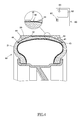
Fig. 3 is a cross sectional view of the tire and shows the tire replacement warning device of the present invention; -
Fig. 4 is a cross sectional view of the tire and shows that the tread of tire is almost worn out and the sensing line of the tire replacement warning device of the present invention is exposed; -
Fig. 5 is a cross sectional view of the tire and shows that the safety face is worn out and the sensing line of the tire replacement warning device of the present invention is broken, and -
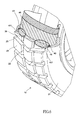
Fig. 6 is a perspective view, partial removed, of the tire and another embodiment of the tire replacement warning device of the present invention. - Referring to
Figs. 1 to 3 , thetire 10 of the present invention is mounted to arim 11 and comprises atread 20 and twosidewalls 21 are located on two sides of thetread 20. Thetread 20 comprisesfirst tread grooves 22 andsecond tread grooves 23 which transversely intersect thefirst tread grooves 22. Thefirst tread grooves 22 are defined along the longitudinal direction of thetread 20. Asafety face 30 protrudes from the inner end of one of thefirst tread groove 22. Asensing device 40 is located in thetread 20 and beneath thesafety face 30. - The
sensing device 40 has asensing line 41 and twointegral circuits sensing line 41 is connected between the twointegral circuits integral circuits sensing device 40 is located in thetread 20 when thetire 10 is manufactured. Thesensing line 41 is located across thetread 20 and the twointegral circuits sidewalls 21 respectively. Thesensing line 41 is located beneath thesafety face 30 so that thesensing line 41 is covered by thesafety face 30 and parallel to the curved surface of thesafety face 30. - A
warning signal receiver 60 is able to receive the wireless signals from thesensing device 40. Thewarning signal receiver 60 comprises aspeaker 61, a receivingportion 62 which receives the specific frequency of the wireless signals from thesensing device 40, and alight emitting member 63 which is connected to thereceiving portion 62. When thereceiving portion 62 receives the specific frequency of the wireless signals from thesensing device 40, thespeaker 61 generates audio signals and thelight emitting member 63 flashes to let the user know that the tire needs to be replaced. - The
warning signal receiver 60 is installed in a vehicle, or thewarning signal receiver 60 is an individual receiver and connected with a power source of the vehicle, or thewarning signal receiver 60 is designed as a software such as an application (App) which can be downloaded by cloud technology to an intellectual phone so as to receive the wireless signals from thesensing device 40. - As shown in
Figs. 3 to 5 , along with the use of thetire 10, the depths of the first andsecond tread grooves safety face 30 is worn out, thesensing line 41 is exposed and directly in contact with the road, the friction may break thesensing line 41. The circuit is then cut off so that theintegral circuits warning signal receiver 60. Thespeaker 61 generates audio signals and thelight emitting member 63 flashes to let the user know that the tire needs to be replaced. - As shown in
Fig. 6 , thesensing device 40 has asensing line 45 and anintegral circuit 43, wherein thesensing line 45 is in a form of a coil and two ends of thesensing line 45 are connected to theintegral circuit 44. Theintegral circuit 43 is located close to thesidewall 21 and thesensing line 45 is located beneath thesafety face 30. Theother safety face 30 is cooperated with another set ofsensing line 45 andintegral circuit 43. When thesafety face 30 is worn out, thesensing line 45 is exposed and directly in contact with the road, the friction may break thesensing line 45. The circuit is then cut off so that theintegral circuit 43 sends a signal to thewarning signal receiver 60. Thespeaker 61 generates audio signals and thelight emitting member 63 flashes to let the user know that the tire needs to be replaced. - The
sensing line 41 can be a straight wire or thesensing line 45 is a coil can achieve the purpose of the invention. Thesensing lines integral circuits - While we have shown and described the embodiment in accordance with the present invention, it should be clear to those skilled in the art that further embodiments may be made without departing from the scope of the present invention.
Claims (10)
- A tire comprising:a tread (20) and two sidewalls (21) on two sides of the tread (20), the tread (20) having multiple tread grooves (22,23) defined therein and a safety face (30) protruding from an inner end of one of the tread grooves (22,23), anda sensing device (40) located in the tread (20) and having a sensing line (41) which is able to emit wireless signals, the sensing line (41) located beneath the safety face (30).
- The tire according to claim 1, wherein the sensing device (40) further comprises an integral circuit (43).
- The tire as claimed in any one of claims 1 and 2, wherein the tread (20) comprises first tread grooves (22) and second tread grooves (23) which transversely intersect the first tread grooves (22), the first tread grooves (22) are defined along a longitudinal direction of the tread (20), the safety face (30) is located in the one of the first tread groove (22).
- The tire as claimed in claim 2, wherein the sensing device (40) comprises two integral circuits (43,44), the sensing line (41) is connected between the two integral circuits (43,44), the sensing line (41) is located across the tread (20) and the two integral circuits (43,44) are located close to two the sidewalls (21) respectively, the sensing line (41) is located across the tread (20) and the safety face (30).
- The tire as claimed in claim 2, wherein the sensing line (45) is in a form of a coil and two ends of the sensing line (45) are connected to the integral circuit (43), the integral circuit (43) is located close to the sidewall, the sensing line (45) is located beneath the safety face (30).
- A tire replacement warning device comprising:a tire as defined in anyone of claims 1 to 5, anda warning signal receiver (60) receiving the wireless signals from the sensing device (40) .
- The device as claimed in claim 6, wherein the warning signal receiver (60) comprises a speaker (61) and a receiving portion (62) which receives the wireless signals from the sensing device (40), the speaker (61) is connected to the receiving portion (62).
- The device as claimed in claim 7, wherein the warning signal receiver (60) comprises a light emitting member (63) which is connected to the receiving portion (62).
- The device as claimed in claim 7, wherein the warning signal receiver (60) is adapted to be installed in a vehicle.
- The device as claimed in claim 7, wherein the warning signal receiver (60) is an individual receiver and adapted to be connected with a power source.
Applications Claiming Priority (1)
| Application Number | Priority Date | Filing Date | Title |
|---|---|---|---|
| TW101135064A TW201412573A (en) | 2012-09-25 | 2012-09-25 | Tire for detecting tire tread wear to safety limit and wear warning device thereof |
Publications (2)
| Publication Number | Publication Date |
|---|---|
| EP2711201A2 true EP2711201A2 (en) | 2014-03-26 |
| EP2711201A3 EP2711201A3 (en) | 2015-02-18 |
Family
ID=49231335
Family Applications (1)
| Application Number | Title | Priority Date | Filing Date |
|---|---|---|---|
| EP13185642.9A Withdrawn EP2711201A3 (en) | 2012-09-25 | 2013-09-24 | Tire replacement warning device |
Country Status (4)
| Country | Link |
|---|---|
| US (1) | US20140083582A1 (en) |
| EP (1) | EP2711201A3 (en) |
| CN (1) | CN103660805A (en) |
| TW (1) | TW201412573A (en) |
Families Citing this family (13)
| Publication number | Priority date | Publication date | Assignee | Title |
|---|---|---|---|---|
| CN105157633A (en) * | 2015-05-13 | 2015-12-16 | 广西梧州运龙港船机械制造有限公司 | Outer gear ring wear automatic detection device |
| US9994082B2 (en) * | 2015-07-31 | 2018-06-12 | Texas Instruments Deutschland, Gmbh | Tire monitoring based on inductive sensing |
| CN105423882A (en) * | 2015-12-29 | 2016-03-23 | 韶山恒旺电气有限公司 | Wheel lining wear detection device |
| CN105539025B (en) * | 2016-01-07 | 2017-05-10 | 西华大学 | A tire safety monitoring device |
| TWI617117B (en) * | 2016-10-19 | 2018-03-01 | 連益輝 | Tire magnetic coil device for vehicles |
| TWI617118B (en) * | 2016-10-19 | 2018-03-01 | 連益輝 | Tire with a coil circuit board |
| TWI617119B (en) * | 2016-10-19 | 2018-03-01 | 連益輝 | Coil circuit board for being used with a tire |
| CN108629758A (en) * | 2017-03-21 | 2018-10-09 | 北京爱德盛业科技有限公司 | A kind of inspection method of the automobile rubber part based on cloud computing |
| TWI692638B (en) * | 2019-01-04 | 2020-05-01 | 益力半導體股份有限公司 | Device and method for detecting thickness of tire skin using sound and non-temporary computer readable recording medium |
| US10980164B2 (en) | 2019-06-26 | 2021-04-20 | Cnh Industrial America Llc | Wear determination for agricultural implement |
| CN110341395A (en) * | 2019-08-23 | 2019-10-18 | 沙洲职业工学院 | An automatic detection device for automobile tire wear |
| CN113263870A (en) * | 2020-02-17 | 2021-08-17 | 建大工业股份有限公司 | Tire wear indication system and tire using the same |
| CN115257241B (en) * | 2022-08-26 | 2023-07-21 | 合肥移瑞通信技术有限公司 | Vehicle safety detection system |
Family Cites Families (7)
| Publication number | Priority date | Publication date | Assignee | Title |
|---|---|---|---|---|
| US3568145A (en) * | 1968-01-19 | 1971-03-02 | Joseph K Dikoff | Tire-warning apparatus |
| US4031508A (en) * | 1975-12-15 | 1977-06-21 | Seita Omori | Puncture alarm device for a tire |
| GB9915052D0 (en) * | 1999-06-28 | 1999-08-25 | Lonsdale Anthony | Apparatus and method for detecting the condition of an item |
| JP4296917B2 (en) * | 2003-12-10 | 2009-07-15 | トヨタ自動車株式会社 | Tire state estimating device and tire |
| JP4812624B2 (en) * | 2004-06-23 | 2011-11-09 | 株式会社ブリヂストン | Tire wear detection system and pneumatic tire |
| US7280036B2 (en) * | 2005-05-04 | 2007-10-09 | Eric Adel Kafrawy | Detection and warning system |
| JP2011189795A (en) * | 2010-03-12 | 2011-09-29 | Pacific Ind Co Ltd | Tire wear detection device |
-
2012
- 2012-09-25 TW TW101135064A patent/TW201412573A/en unknown
- 2012-10-12 US US13/651,198 patent/US20140083582A1/en not_active Abandoned
- 2012-10-15 CN CN201210387742.5A patent/CN103660805A/en active Pending
-
2013
- 2013-09-24 EP EP13185642.9A patent/EP2711201A3/en not_active Withdrawn
Non-Patent Citations (1)
| Title |
|---|
| None |
Also Published As
| Publication number | Publication date |
|---|---|
| TW201412573A (en) | 2014-04-01 |
| CN103660805A (en) | 2014-03-26 |
| US20140083582A1 (en) | 2014-03-27 |
| EP2711201A3 (en) | 2015-02-18 |
Similar Documents
| Publication | Publication Date | Title |
|---|---|---|
| EP2711201A2 (en) | Tire replacement warning device | |
| USD685724S1 (en) | Tire tread | |
| EP4045364A4 (en) | Dynamic vehicle warning signal emission | |
| JP6540689B2 (en) | Radar module, transportation device, and object identification method | |
| USD818938S1 (en) | Tire tread | |
| MX2016003399A (en) | Tire structure for externally mounted device. | |
| US10688837B2 (en) | Tire-mounted sensor and sensor device used for same | |
| US20160096403A1 (en) | Tire positioning method and tire positioning system | |
| USD748050S1 (en) | Tire tread | |
| USD885320S1 (en) | Tyre | |
| AR102752A1 (en) | INITIATION OF ELECTRONIC DETONATOR | |
| ZA201905551B (en) | Attachment for a vehicle wheel | |
| MY165208A (en) | Vehicle wheel | |
| WO2017110398A1 (en) | Tire-mounted sensor | |
| CN110462705A (en) | Modulated warning lights for vehicles | |
| CN107776485A (en) | Warning device for urban public transport vehicle, especially tramcar | |
| US10032372B1 (en) | Traffic signal system | |
| USD778754S1 (en) | Wireless doorbell receiver | |
| US20170238642A1 (en) | Helmet safety system | |
| USD821299S1 (en) | Tire tread | |
| USD829638S1 (en) | Tire tread | |
| MY186540A (en) | Eurobalise vehicle device and method for operating a eurobalise vehicle device | |
| CN203586025U (en) | Automobile LED side marker lamp | |
| JP3202142U (en) | Alarm device | |
| USD816595S1 (en) | Tire tread |
Legal Events
| Date | Code | Title | Description |
|---|---|---|---|
| PUAI | Public reference made under article 153(3) epc to a published international application that has entered the european phase |
Free format text: ORIGINAL CODE: 0009012 |
|
| AK | Designated contracting states |
Kind code of ref document: A2 Designated state(s): AL AT BE BG CH CY CZ DE DK EE ES FI FR GB GR HR HU IE IS IT LI LT LU LV MC MK MT NL NO PL PT RO RS SE SI SK SM TR |
|
| AX | Request for extension of the european patent |
Extension state: BA ME |
|
| 17P | Request for examination filed |
Effective date: 20140915 |
|
| RBV | Designated contracting states (corrected) |
Designated state(s): AL AT BE BG CH CY CZ DE DK EE ES FI FR GB GR HR HU IE IS IT LI LT LU LV MC MK MT NL NO PL PT RO RS SE SI SK SM TR |
|
| PUAL | Search report despatched |
Free format text: ORIGINAL CODE: 0009013 |
|
| AK | Designated contracting states |
Kind code of ref document: A3 Designated state(s): AL AT BE BG CH CY CZ DE DK EE ES FI FR GB GR HR HU IE IS IT LI LT LU LV MC MK MT NL NO PL PT RO RS SE SI SK SM TR |
|
| AX | Request for extension of the european patent |
Extension state: BA ME |
|
| RIC1 | Information provided on ipc code assigned before grant |
Ipc: B60C 11/24 20060101AFI20150115BHEP |
|
| STAA | Information on the status of an ep patent application or granted ep patent |
Free format text: STATUS: THE APPLICATION IS DEEMED TO BE WITHDRAWN |
|
| 18D | Application deemed to be withdrawn |
Effective date: 20151107 |