EP2711157A1 - Blasformmaschine mit Dämpfung für deren Steuerung - Google Patents
Blasformmaschine mit Dämpfung für deren Steuerung Download PDFInfo
- Publication number
- EP2711157A1 EP2711157A1 EP13185232.9A EP13185232A EP2711157A1 EP 2711157 A1 EP2711157 A1 EP 2711157A1 EP 13185232 A EP13185232 A EP 13185232A EP 2711157 A1 EP2711157 A1 EP 2711157A1
- Authority
- EP
- European Patent Office
- Prior art keywords
- damping
- forming
- control device
- drive
- plastic preforms
- Prior art date
- Legal status (The legal status is an assumption and is not a legal conclusion. Google has not performed a legal analysis and makes no representation as to the accuracy of the status listed.)
- Granted
Links
Images

Classifications
-
- B—PERFORMING OPERATIONS; TRANSPORTING
- B29—WORKING OF PLASTICS; WORKING OF SUBSTANCES IN A PLASTIC STATE IN GENERAL
- B29C—SHAPING OR JOINING OF PLASTICS; SHAPING OF MATERIAL IN A PLASTIC STATE, NOT OTHERWISE PROVIDED FOR; AFTER-TREATMENT OF THE SHAPED PRODUCTS, e.g. REPAIRING
- B29C49/00—Blow-moulding, i.e. blowing a preform or parison to a desired shape within a mould; Apparatus therefor
- B29C49/42—Component parts, details or accessories; Auxiliary operations
- B29C49/4236—Drive means
- B29C49/42362—Electric drive means, e.g. servomotors
-
- B—PERFORMING OPERATIONS; TRANSPORTING
- B29—WORKING OF PLASTICS; WORKING OF SUBSTANCES IN A PLASTIC STATE IN GENERAL
- B29C—SHAPING OR JOINING OF PLASTICS; SHAPING OF MATERIAL IN A PLASTIC STATE, NOT OTHERWISE PROVIDED FOR; AFTER-TREATMENT OF THE SHAPED PRODUCTS, e.g. REPAIRING
- B29C49/00—Blow-moulding, i.e. blowing a preform or parison to a desired shape within a mould; Apparatus therefor
- B29C49/08—Biaxial stretching during blow-moulding
- B29C49/10—Biaxial stretching during blow-moulding using mechanical means for prestretching
- B29C49/12—Stretching rods
-
- B—PERFORMING OPERATIONS; TRANSPORTING
- B29—WORKING OF PLASTICS; WORKING OF SUBSTANCES IN A PLASTIC STATE IN GENERAL
- B29C—SHAPING OR JOINING OF PLASTICS; SHAPING OF MATERIAL IN A PLASTIC STATE, NOT OTHERWISE PROVIDED FOR; AFTER-TREATMENT OF THE SHAPED PRODUCTS, e.g. REPAIRING
- B29C49/00—Blow-moulding, i.e. blowing a preform or parison to a desired shape within a mould; Apparatus therefor
- B29C49/28—Blow-moulding apparatus
- B29C49/30—Blow-moulding apparatus having movable moulds or mould parts
- B29C49/36—Blow-moulding apparatus having movable moulds or mould parts rotatable about one axis
-
- B—PERFORMING OPERATIONS; TRANSPORTING
- B29—WORKING OF PLASTICS; WORKING OF SUBSTANCES IN A PLASTIC STATE IN GENERAL
- B29C—SHAPING OR JOINING OF PLASTICS; SHAPING OF MATERIAL IN A PLASTIC STATE, NOT OTHERWISE PROVIDED FOR; AFTER-TREATMENT OF THE SHAPED PRODUCTS, e.g. REPAIRING
- B29C49/00—Blow-moulding, i.e. blowing a preform or parison to a desired shape within a mould; Apparatus therefor
- B29C49/42—Component parts, details or accessories; Auxiliary operations
- B29C49/62—Venting means
- B29C2049/6271—Venting means for venting blowing medium, e.g. using damper or silencer
-
- B—PERFORMING OPERATIONS; TRANSPORTING
- B29—WORKING OF PLASTICS; WORKING OF SUBSTANCES IN A PLASTIC STATE IN GENERAL
- B29C—SHAPING OR JOINING OF PLASTICS; SHAPING OF MATERIAL IN A PLASTIC STATE, NOT OTHERWISE PROVIDED FOR; AFTER-TREATMENT OF THE SHAPED PRODUCTS, e.g. REPAIRING
- B29C49/00—Blow-moulding, i.e. blowing a preform or parison to a desired shape within a mould; Apparatus therefor
- B29C49/08—Biaxial stretching during blow-moulding
- B29C49/10—Biaxial stretching during blow-moulding using mechanical means for prestretching
- B29C49/122—Drive means therefor
- B29C49/123—Electric drives, e.g. linear motors
Definitions
- the present invention relates to an apparatus for forming plastic preforms into plastic containers.
- plastic bottles are made from plastic preforms which are first heated and then expanded by means of blowing nozzles.
- a forming device hereinafter also referred to as stretch blow molding machine
- a transport device such as a blowing wheel
- These blowing stations of such a stretch blow molding machine are the centerpiece in which the plastic preforms are blown by the application of an internal pressure to the plastic bottles.
- the preheated plastic preform - hereinafter also referred to as preform - is thereby positioned between the mold carriers in the mold.
- a stretching rod which is usually driven by a drive device, such as a linear motor
- the actual inflation process follows.
- the applied internal pressure presses the plastic preform against the mold from the inside, as a result of which the container assumes its desired shape.
- the present invention is therefore based on the object to improve the life of these electronic devices or control devices and in particular to reduce the force acting on these control devices or electronic components forces or accelerations.
- a device according to the invention for forming plastic preforms into plastic containers has a transport device on which a multiplicity of forming stations for reshaping the plastic preforms are arranged.
- these forming stations each have at least two mutually movable blow moldings which can be moved between an open state and a closed state of the forming station and form a cavity in the closed state of the forming station, within which the plastic preforms are deformable to the plastic containers.
- the conversion stations each have a loading device, which act on the plastic preforms to expand them with a gaseous medium and in particular with compressed air.
- the conversion stations each have stretching bars which can be inserted into the plastic preforms in order to stretch them in their longitudinal direction.
- the conversion stations each have at least one drive device which drives a movement required for the deformation process.
- a control device for controlling this drive device is provided.
- this control device is arranged by means of a damping device on the device and in particular on at least one forming station.
- each conversion station is assigned such a control device, but it would also be possible that a control device is used to control a plurality of transformation stations. Also, a plurality of control devices-in particular by means of damping devices-could be arranged at a conversion station.
- the invention therefore proposes to solve the usually rigid connection in the prior art with the device or the forming station. This is instead replaced by a floating or damped connection.
- movement may be about a movement of the stretch rod, a tuyere or even a pivoting movement of the two blow moldings or side parts or even a movement of a bottom mold for the blow mold.
- the transport device is a rotatable transport device and in particular a blow wheel, the plurality of conversion stations or blowing stations being arranged on an outer circumference of this blow wheel.
- At least one drive device is preferably an electromotive drive device.
- this drive device could also be a magnetic, hydraulic or pneumatic drive device.
- the control device preferably has a multiplicity of electronic components and in particular of semiconductor components.
- a drive device for moving the stretch rod is provided and a control device for controlling this drive device and this control device for controlling the drive device is preferably arranged by means of the damping device at the forming station.
- the control device is advantageously arranged on a support of the said conversion station.
- control device has at least one converter unit or a converter.
- this is in particular a servo converter which serves to drive the drive device (s).
- This drive device (s) are advantageously designed as servo linear motors.
- control device is arranged on a carrier and this carrier is in turn arranged by means of the at least one damping device at the forming station.
- the damping device has a plurality of damping elements, by means of which the control device is arranged at the forming station.
- the individual damping elements are spaced from each other.
- the control device or the carrier, on which the control device is arranged is advantageously mounted at the forming station with a multipoint bearing.
- at least two damping elements and preferably three damping elements are provided to support the control device. It is possible that these three damping elements span an isosceles triangle, by means of which the control device or its carrier is mounted. In this way, a particularly efficient damping can be achieved.
- At least one damping device has a symmetrical shape and in particular a circular cross section. In this way, a same attenuation can be achieved regardless of a load direction in a given plane.
- the damping device has at least one damping element made of an elastomer.
- at least one damping element is at least partially made of a plastic or elastomer.
- this damping element can be arranged between two harder components, in particular two metal parts.
- one end of a vibration decoupling element is fixedly connected to the forming station and the other end is fixedly connected to the carriers or the components of the control device, wherein an elastomer is located between these two ends.
- the said connecting elements or damping elements and thus also the damping device are connected directly to approximately one element of the Reckstangenantriebs and in particular a stator of this Reckstangenantriebs.
- the damping device has a damping element which has a density of less than 2.1 g / cm 3 .
- Such materials are particularly suitable for use in the present machines.
- a cooling device is provided for cooling the control device and / or the drive controlled by this control device.
- the above-mentioned drive and in particular its stator that is, the stator of the stretching drive and also the support plate or the control device and other electronic components are supplied together with a cooling medium.
- these components are cooled by a liquid, but it would also be a gas cooling or air cooling possible.
- the above-mentioned carrier on which the control device is arranged could have cooling channels.
- a cooling medium first cools the drive and then (or downstream) its control device.
- the damping device is provided within a pitch circle of the transport device. In this way it is achieved that the co-rotating mass is further in the direction of the center of the transport device or the blowing wheel.
- the arrangement for vibration decoupling is arranged within the pitch circle of the blowing wheel and / or in a vertical or radial direction behind a stretching rod axis.
- control device if appropriate together with the damping device, to be located behind a mold carrier of the blowing station or behind a blowing nozzle. This means that the height at which the control device is arranged can vary, in particular in dependence on the controlled drive.
- a control device which is assigned to a plurality of blowing stations, or which controls a plurality of blow molding stations. These are in particular one of the above-mentioned vibration-decoupled control devices.
- control device if necessary together with a carrier
- the control device is arranged on the blowing wheel, it may even be possible to dispense with the damping devices described above, since the blowing wheel is already subject to substantially less vibration than the individual transformation stations because of its high mass. It would thus be possible, in contrast to devices of the prior art, not to arrange the control means for controlling the individual drives of the conversion stations at the transformation stations themselves, but at the transport means or the blowing wheel.
- the control device is arranged relatively far inside on the blowing wheel so as to reduce the respective centrifugal forces.
- the present invention is further directed to a method for forming plastic preforms to plastic containers, wherein plastic preforms are converted by means of at least one arranged on a transporting Umformungsstation to the plastic containers and are acted upon for the purpose of this transformation by means of at least one impingement device with a flowable medium.
- the non-forming station performs at least one and preferably a plurality of movements for forming the plastic preforms with at least one drive device and preferably with a plurality of drive devices, and this drive device is controlled by a control device.
- control device is arranged on the device by means of a damping device such that vibrations caused by the movements are not transmitted to the control device without damping or at least partially attenuated.
- the vibrations arising in the course of the deformation process, in particular of the transformation station are transmitted to the control device only in a damped manner, so that the sensitive electronic elements are spared.
- the plastic preforms are stretched for the purpose of forming by means of a stretch rod in their longitudinal direction.
- a motion or vibration generated by the movement of this stretch rod is transmitted only attenuated to the control device.
- a device of the type described above is used for the inventive method.
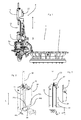
- Fig. 1 shows a partial representation of a device 1 according to the invention for forming plastic preforms to plastic containers.
- This has a transport device 2, at which a plurality of transformation stations 4 (only one shown) is arranged.
- These forming stations (hereinafter also referred to as blowing stations) 4 each have loading devices in the form of a respective blowing nozzle 8, which is movable in a longitudinal direction L and on mouths of the inside of two blow mold 6a, 6b (only the blow mold 6a is visible) arranged plastic preforms 10 is placed in order to pressurize them with compressed air for their expansion.
- a drive device is provided, which moves this application device 8 in the longitudinal direction L.
- the device has a valve block which has a plurality of valves with which the supply of the blown air to the plastic preforms can be controlled.
- the reference numeral 12 denotes a stretching rod, which is insertable in the plastic preforms 10 in the context of the forming process in order to stretch them in the longitudinal direction L. Also, this stretch rod 12 is thus moved in the longitudinal direction L.
- the reference numeral 14 denotes a drive which performs this movement of the stretch rod 12. This is in particular a linear motor. To control this linear motor 14, a control device 20 is provided, which in particular also has a servo-converter.
- the reference numeral 10 indicates the plastic preform which is expanded by means of the blowing air. However, the preform is only partially recognizable here, as most of it is already inside the blow molds. Support shells are usually arranged on the blow mold carriers 6a shown, and blow mold parts are in turn arranged on these carrier shells. These blow moldings together form the cavity within which the plastic preforms are expanded to the plastic containers.
- a preheated plastic preform is positioned between the mold carriers in the mold. After being stretched by the stretch rod which, as mentioned above, is driven by a linear motor, the actual inflation process follows. The applied internal pressure presses the plastic preform against the blow mold from the inside, whereby the bottle assumes the desired shape.
- FIG. 2 shows a detailed representation of the device according to the invention in particular with an illustration of the arrangement according to the invention of the control device 20. It shows FIG. 2 A detailed representation of the region of the drive device 14 can be seen that a carrier 24 or a carrier plate is arranged on this drive device 14.
- FIG. 2 shows a detailed representation of the in FIG. 1 and in particular that region of the device in which the drive device for driving the stretch rod 12 is arranged. It should be noted that corresponding arrangements are also conceivable in the drive for moving the tuyere or the mold carrier parts.
- the carrier 24 is arranged. This carrier 24 is here attached to two holding devices 42 and 44 via damping elements 26a, 26b, 26c. These damping elements 26a, 26b, 26c here form the damping device 26
- the carrier 24 is arranged "floating" on the drive device 14 or on a carrier of the conversion station.
- a mounting bracket which can be screwed to the drive device 14, for example.
- the damping elements 26a, 26b and 26c may for example be designed as a rubber buffer.
- the reference numeral 44 denotes a support strip, which in turn has two holding elements 44a and 44b, which hold the carrier via the damping elements 26a, b, c.
- FIG. 3 shows a side view of in FIG. 2 shown device.
- the control device 20 which, for example, a servo inverter may have arranged.
- the holding elements 42 and 44 wherein the holding element 42 is designed here as a bracket and the holding elements 44 as elements which are arranged on the support bar 44.
- Reference numeral 38 denotes a secondary part of the drive 14 moving up and down in the direction L.
- FIG. 4 shows a detailed representation of the damping.
- the carrier 24 and the support plate with the control device 20 fixed thereto can be seen again.
- the retaining element 42 is shown in detail here. This is screwed by means of a screw 56 to the drive device 14.
- the vibration decoupling of the control device is performed.
- the mounting bracket 42 and the in FIG. 3 shown support strip 44 are screwed here each with the blowing station.
- the control device 20 is, as mentioned, rigidly connected to the carrier or the adapter plate.
- the support 24 and the control device are fixed in a floating manner with respect to the transformation station 4, ie the dampers allow a relative movement of the control device 20 with respect to the conversion station, in all three axial directions.
- the carrier plate is provided with a relatively high weight, so that it is still not excessively vibrated.
- the mass of this carrier is between 0.5kg and 3kg, preferably between 0.5kg and 2kg, preferably between 0.5kg and 1.5kg. It is also possible that the mass is selected depending on the vibrations occurring, for example so that no resonance frequencies occur. It would also be possible that the mass of this carrier 24 (for example by screwing on additional weight pieces) is variable.
- the damping element 26c is screwed rigidly at both ends to the fastening angle 42 and the carrier 24. With its elastic body, this damping element 26a, b, c produces a flexible connection between the transformation station and the electronic component 20.
- the damping element 26c may have a projection 54 which is inserted into a corresponding recess 52 in the carrier 24 and preferably screwed.
- the damping element As mentioned, with the damping element and the two further damping elements (not shown), it is possible in particular to achieve a floating or floating suspension in a plane which is perpendicular to the plane of the figure. In addition, however, the damping element also allows a certain oscillation in a direction transverse thereto, i. here in particular in a direction which extends perpendicular to the said plane or in the plane of the figure.
- the carrier 24 can be mounted in different ways or on different elements of the blow molding station. It would also be possible not to arrange the carrier at the forming station, but at the blowing wheel (see. FIG. 1 ). However, the carrier 24 is preferably as shown in FIG FIG. 4 shown, standing, that is arranged in a vertical orientation, and not lying or in the horizontal direction or the attenuation aligned accordingly. This is due to the fact that the vibrations that occur largely affect the direction perpendicular to the plane of the figure and therefore the highest damping requirements are to be set in this direction. In particular, the stretching rod movement will generate vibrations in a special way, which run in the longitudinal direction L. Thus, the damping elements shown here are also suitable, in particular, for compensating or damping such vibrations.
- damping element 26c has the advantage that it is relatively easy and inexpensive to implement.
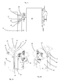
- FIGS. 5a and 5b illustrate in particular the cooling of the control device 20.
- a cooling device 60 is provided in the form of liquid cooling.
- the drive device 14 cooling channels 62, 64, through which a flowable and in particular liquid cooling medium can flow.
- a transverse channel (not visible) is furthermore provided, through which the cooling medium can pass from the channel 64 to a connection 66.
- the cooling medium flows via a line 68 to the carrier or the adapter plate 24.
- this carrier has in its interior a channel for cooling.
- FIG. 5b is also the second port 67, with the line 68 is connected to the carrier 24, visible.
- the reference numeral 65 denotes a cavity within which the secondary part of the drive 14 can move.
- the conduit 68 is a flexible conduit.
- the reference numeral 63 denotes a gap extending in the longitudinal direction L of the drive device 14 or its housing. Opposite this gap 63 is (see. Fig. 5b ) a further extending in the longitudinal direction L recess 69 is provided, which is formed in contrast to the gap 63 is not continuous in the longitudinal direction L.
- a coil is preferably arranged and in particular fixedly arranged. Within this coil, the secondary part can move.
- Fig. 6a and 6b show a further embodiment of the damping device 26.
- a disk 72 is arranged on the drive device 14 by means of a fastening means 75 such as a screw.
- This disk 72 which may be made of metal or a plastic, can be fixedly connected to the carrier (not shown) to which in turn the control device is arranged.
- two gaps 74 a, 74 b are formed and in a corner region a damping element 76 as here an O-ring is provided which keeps the drive means 14 and the disc 72 at a distance and so the attenuated by the drive device 14 outgoing vibrations.
- Fig. 6b embodiment shown is similar to in Fig. 6a shown embodiment, here also two gaps 74a and 74b are provided, however, two O-rings 76a, 76b, which hold the disc 72 on the one hand and the drive means 14 on the other hand at a distance and so again cause the damping.
- FIGS. 7a-7d illustrate a further embodiment of a damping device 26.
- three elastomer elements or damping elements 86a, 86b, 86c are provided, by means of which the carrier 24 is arranged on the drive device 14.
- the damping element 86c is between the drive device 14 and the carrier 24 is arranged.
- Another damping element 86a supports a fastener 82 relative to the carrier.
- This damping element 86a may be formed as an elastomeric perforated disc.
- An O-ring 85 can be provided on the surface of this disk 86a facing the carrier 24. It is also possible that the disc 86a itself is rigid and the damping by the O-ring 85 is effected.
- the damping element 86b is here designed as a cylindrical body which surrounds the shaft of the fastening means 82.
- a disc 86a is screwed to the drive device 14 by means of the O-ring 85 and the fastening means 82.
- the damping element 86c is formed here again from an elastomer and additionally has an annular body 87 (which is made in particular of a metal or a harder plastic) on.
- the damping is achieved here in particular by the damping element 86c and the O-ring 85.
- This ring-like body 87 or the metal disk 87 serves here as a centering of the damping element 86c and can be vulcanized into the damping element 86c, for example. It is possible that this disc is larger than the corresponding bore in the carrier 24th
- Fig. 7c shows a further embodiment in which the in Fig. 7a shown damping elements 86a and 86b are integrally formed, whereby the production is simplified.
- Fig. 7d shows a further illustration for illustrating the damping element 86c, which is embedded here in two metal discs 87.
Landscapes
- Engineering & Computer Science (AREA)
- Manufacturing & Machinery (AREA)
- Mechanical Engineering (AREA)
- Vibration Prevention Devices (AREA)
- Blow-Moulding Or Thermoforming Of Plastics Or The Like (AREA)
Abstract
Description
- Die vorliegende Erfindung bezieht sich auf eine Vorrichtung zum Umformen von Kunststoffvorformlingen zu Kunststoffbehältnissen. In der Getränke herstellenden Industrie ist es bekannt, dass Kunststoffflaschen aus Kunststoffvorformlingen hergestellt werden, die zunächst erwärmt und anschließend mittels Blasdüsen expandiert werden. Eine derartige Umformungseinrichtung, im Folgenden auch als Streckblasmaschine bezeichnet, weist üblicherweise eine Transporteinrichtung auf, wie etwa ein Blasrad, an dem eine Vielzahl von Umformungsstationen bzw. Blasstationen angeordnet ist. Diese Blasstationen einer derartigen Streckblasmaschine sind dabei das Herzstück, in denen die Kunststoffvorformlinge durch das Anlegen eines Innendrucks zu den Kunststoffflaschen geblasen werden. Der vorgewärmte Kunststoffvorformling - im Folgenden auch als Preform bezeichnet - wird dabei zwischen den Formträgern in der Form positioniert. Nach dem Recken durch eine Reckstange, die üblicherweise von einer Antriebseinrichtung, wie beispielsweise einem Linearmotor, angetrieben wird, folgt der eigentliche Aufblasprozess. Der angelegte Innendruck presst den Kunststoffvorformling von innen gegen die Form, wodurch das Behältnis seine gewünschte Form annimmt.
- Im Rahmen eines derartigen Blasformprozesses treten dabei die unterschiedlichsten Bewegungen auf, wie etwa die Bewegung der Blasformteile zum Öffnen und Schließen der Blasform, die Bewegungen der Reckstange, die Bewegungen einer Blasdüse und dergleichen. Durch den Blasvorgang und die kinematische Bewegung beim Öffnen und Schließen der Formträger entstehen damit relativ hohe Prozesskräfte, welche auch die vollständige Umformungsstation zum Schwingen bringen. Da üblicherweise auch elektronische Bauteile, wie beispielsweise Servoumrichter, starr an der Blasstation angeordnet sind, werden die beschriebenen Prozesskräfte direkt an diese weitergegeben. Einige der in den Blasstationen verbauten und verwendeten elektronischen Einrichtungen können dann diesen Beschleunigungskräften bzw. den auftretenden Schwingungen nicht standhalten und es kommt häufig zu deren Ausfall.
- Der vorliegenden Erfindung liegt daher die Aufgabe zugrunde, die Lebensdauer dieser elektronischen Geräte bzw. Steuerungseinrichtungen zu verbessern und insbesondere die auf diese Steuerungseinrichtungen bzw. elektronischen Bauteile wirkenden Kräfte bzw. Beschleunigungen zu verringern.
- Diese Aufgabe wird erfindungsgemäß durch die Gegenstände der unabhängigen Ansprüche erreicht. Vorteilhafte Ausführungsformen und Weiterbildungen sind Gegenstand der Unteransprüche.
- Eine erfindungsgemäße Vorrichtung zum Umformen von Kunststoffvorformlingen zu Kunststoffbehältnissen weist eine Transporteinrichtung auf, an der eine Vielzahl von Umformungsstationen zum Umformen der Kunststoffvorformlinge angeordnet ist. Dabei weisen diese Umformungsstationen jeweils wenigstens zwei zueinander bewegliche Blasformteile auf, die zwischen einem geöffneten Zustand und einem geschlossenen Zustand der Umformungsstation bewegt werden können und in dem geschlossenen Zustand der Umformungsstation einen Hohlraum ausbilden, innerhalb dessen die Kunststoffvorformlinge zu den Kunststoffbehältnissen umformbar sind. Weiterhin weisen die Umformungsstationen jeweils eine Beaufschlagungseinrichtung auf, welche die Kunststoffvorformlinge zu deren Expansion mit einem gasförmigen Medium und insbesondere mit Druckluft beaufschlagen.
- Weiterhin weisen die Umformungsstationen jeweils Reckstangen auf, welche in die Kunststoffvorformlinge einführbar sind, um diese in deren Längsrichtung zu dehnen.
- Weiterhin weisen die Umformungsstationen jeweils wenigstens eine Antriebseinrichtung auf, welche eine für den Umformungsvorgang erforderliche Bewegung antreibt. Daneben ist auch eine Steuerungseinrichtung zum Steuern dieser Antriebseinrichtung vorgesehen.
- Vorteilhaft ist dabei diese Steuerungseinrichtung mittels einer Dämpfungseinrichtung an der Vorrichtung und insbesondere an wenigstens einer Umformungsstation angeordnet.
- Dabei ist es möglich, dass jeder Umformungsstation eine derartige Steuerungseinrichtung zugeordnet ist, es wäre jedoch auch möglich, dass eine Steuerungseinrichtung zum Ansteuern mehrerer Umformungsstationen dient. Auch könnten an einer Umformungsstation mehrere Steuerungseinrichtungen -insbesondere mittels Dämpfungseinrichtungen - angeordnet sein.
- Wie oben erwähnt, ist angesichts der relativ hohen physikalischen Belastung durch Prozesskräfte auf die empfindlichen elektronischen Bauteile stets mit einer hohen Ausfallquote zu rechnen. Die Erfindung schlägt daher vor, die im Stand der Technik üblicherweise starre Verbindung mit der Vorrichtung bzw. der Umformungsstation zu lösen. Diese wird stattdessen durch eine schwimmende bzw. gedämpfte Verbindung ersetzt. Bei er der für den Umformungsvorgang erforderlichen bzw. verwendeten Bewegung kann es sich etwa um eine Bewegung der Reckstange, einer Blasdüse oder auch um eine Schwenkbewegung der beiden Blasformteile bzw. Seitenteile oder aber auch um eine Bewegung einer Bodenform für die Blasform handeln.
- Vorteilhaft handelt es sich bei der Transporteinrichtung um eine drehbare Transporteinrichtung und insbesondere um ein Blasrad, wobei die Vielzahl von Umformungsstationen bzw. Blasstationen an einem Außenumfang dieses Blasrads angeordnet ist.
- Bevorzugt ist wenigstens eine Antriebseinrichtung eine elektromotorische Antriebseinrichtung. Daneben könnte es sich bei dieser Antriebseinrichtung jedoch auch um eine magnetische, hydraulische oder pneumatische Antriebseinrichtung handeln. Die Steuerungseinrichtung weist dabei bevorzugt eine Vielzahl von elektronischen Bauteilen und insbesondere von Halbleiterbauteilen auf.
- Bei einer weiteren vorteilhaften Ausführungsform ist eine Antriebseinrichtung zum Bewegen der Reckstange vorgesehen sowie eine Steuerungseinrichtung zum Steuern dieser Antriebseinrichtung und diese Steuerungseinrichtung zum Steuern der Antriebseinrichtung ist bevorzugt mittels der Dämpfungseinrichtung an der Umformungsstation angeordnet. Vorteilhaft ist dabei die Steuerungseinrichtung an einen Träger der besagten Umformungsstation angeordnet.
- Bei einer weiteren vorteilhaften Ausführungsform weist die Steuerungseinrichtung wenigstens eine Umrichtereinheit bzw. einen Umrichter auf. Vorzugsweise handelt es sich dabei insbesondere um einen Servoumrichter, der zum Ansteuern der Antriebseinrichtung(en) dient. Diese Antriebseinrichtung(en) sind vorteilhaft als Servo - Linearmotoren ausgeführt.
- Bei einer weiteren vorteilhaften Ausführungsform ist die Steuerungseinrichtung auf einem Träger angeordnet und dieser Träger ist wiederum mittels der wenigstens einen Dämpfungseinrichtung an der Umformungsstation angeordnet.
- Bei einer weiteren vorteilhaften Ausführungsform weist die Dämpfungseinrichtung mehrere Dämpfungselemente auf, mittels denen die Steuerungseinrichtung an der Umformungsstation angeordnet ist. Vorteilhaft sind dabei die einzelnen Dämpfungselemente zueinander beabstandet. Damit wird vorteilhaft die Steuerungseinrichtung bzw. der Träger, an dem die Steuerungseinrichtung angeordnet ist, mit einer Mehrpunktlagerung an der Umformungsstation gelagert. Vorteilhaft sind wenigstens zwei Dämpfungselemente und bevorzugt drei Dämpfungselemente vorgesehen, um die Steuerungseinrichtung zu lagern. Dabei ist es möglich, dass diese drei Dämpfungselemente ein gleichschenkliges Dreieck aufspannen, mittels denen die Steuerungseinrichtung bzw. deren Träger gelagert ist. Auf diese Weise kann eine besonders effiziente Dämpfung erreicht werden.
- Vorteilhaft weist wenigstens eine Dämpfungseinrichtung eine symmetrische Gestalt und insbesondere einen kreisförmigen Querschnitt auf. Auf diese Weise kann eine gleiche Dämpfung unabhängig von einer Belastungsrichtung in einer vorgegebenen Ebene erreicht werden.
- Bei einer weiteren vorteilhaften Ausführungsform weist die Dämpfungseinrichtung wenigstens ein aus einem Elastomer hergestelltes Dämpfungselement auf. Allgemein ist wenigstens ein Dämpfungselement wenigstens bereichsweise aus einem Kunststoff bzw. Elastomer hergestellt. Dabei kann dieses Dämpfungselement zwischen zwei härteren Bauteilen, insbesondere zwei Metallteilen, angeordnet sein.
- Auf diese Weise besteht keine metallische Verbindung zwischen der Steuerungseinrichtung bzw. deren Träger und der Umformungsstation.
- Bei einer weiteren vorteilhaften Ausführungsform ist ein Ende eines Elements zur Schwingungsentkopplung fest mit der Umformungsstation und das andere Ende fest mit den Trägern bzw. den Bauteilen der Steuerungseinrichtung verbunden, wobei sich zwischen diesen beiden Enden ein Elastomer befindet.
- So wäre es beispielsweise möglich, dass die besagten Verbindungselemente bzw. Dämpfungselemente und damit auch die Dämpfungseinrichtung direkt etwa mit einem Element des Reckstangenantriebs und insbesondere einem Stator dieses Reckstangenantriebs verbunden sind.
- Bei einer weiteren vorteilhaften Ausführungsform weist die Dämpfungseinrichtung ein Dämpfungselement auf, welches eine Dichte von weniger als 2,1 g/cm3 aufweist. Derartige Materialien sind besonders zur Verwendung in den vorliegenden Maschinen geeignet.
- Bei einer weiteren vorteilhaften Ausführungsform ist eine Kühleinrichtung zum Kühlen der Steuerungseinrichtung und/oder des von dieser Steuerungseinrichtung gesteuerten Antriebs vorgesehen. Dabei ist es möglich, dass der oben besagte Antrieb und insbesondere dessen Stator, das heißt der Stator des Reckantriebs und auch die Trägerplatte bzw. die Steuerungseinrichtung und andere elektronische Bauteile gemeinsam mit einem Kühlmedium versorgt werden. Dabei ist es möglich, dass diese Bauteile durch eine Flüssigkeit gekühlt werden, es wäre jedoch auch eine Gaskühlung bzw. eine Luftkühlung möglich. So könnte etwa der oben erwähnte Träger, auf dem die Steuerungseinrichtung angeordnet ist, Kühlkanäle aufweisen. Vorzugsweise ist eine Verbindungsleitung zwischen der Kühleinrichtung, welche den Antrieb selbst kühlt und dem besagten Träger angeordnet. Vorteilhaft kühlt dabei ein Kühlmedium zunächst den Antrieb und dann (bzw. stromabwärts) dessen Steuerungseinrichtung.
- Bei einer weiteren vorteilhaften Ausführungsform ist die Dämpfungseinrichtung innerhalb eines Teilkreises der Transporteinrichtung vorgesehen. Auf diese Weise wird erreicht, dass sich die mitdrehende Masse weiter in Richtung des Zentrums der Transporteinrichtung bzw. des Blasrades befindet.
- Bei einer weiteren vorteilhaften Ausführungsform ist die Anordnung zur Schwingungsentkopplung innerhalb des Teilkreises des Blasrades angeordnet und/oder in einer senkrechten bzw. radialen Richtung hinter einer Reckstangenachse.
- Es wäre jedoch auch möglich, dass sich die Steuerungseinrichtung gegebenenfalls gemeinsam mit der Dämpfungseinrichtung hinter einem Formträger der Blasstation oder auch hinter einer Blasdüse befindet. Dies bedeutet, dass die Höhe, auf der die Steuerungseinrichtung angeordnet ist, variieren kann, insbesondere in Abhängigkeit von dem gesteuerten Antrieb.
- Bei einer weiteren vorteilhaften Ausführungsform ist eine Steuerungseinrichtung vorgesehen, die mehreren Blasstationen zugeordnet ist, bzw. die mehrere Blasstationen ansteuert. Dabei handelt es sich hier insbesondere um eine der oben genannten schwingungsentkoppelten Steuerungseinrichtungen.
- Es wäre dabei auch möglich, dass eine derartige Steuerungseinrichtung, die insbesondere schwingungsentkoppelt ist, sich zwischen den Blasstationen befindet.
- Zusätzlich oder alternativ wäre es auch möglich, die Steuerungseinrichtung (ggfs. gemeinsam mit einem Träger) nicht an den Umformungsstationen anzuordnen, sondern an dem Blasrad. Falls die Steuerungseinrichtung an dem Blasrad angeordnet ist, kann gegebenenfalls sogar auf die oben beschriebenen Dämpfungseinrichtungen verzichtet werden, da das Blasrad bereits aufgrund seiner hohen Masse wesentlich weniger Schwingungen unterworfen ist, als die einzelnen Umformungsstationen. Dabei wäre es also möglich, im Gegensatz zu Vorrichtungen aus dem Stand der Technik, die Steuerungseinrichtungen zum Steuern der einzelnen Antriebe der Umformungsstationen nicht an den Umformungsstationen selbst anzuordnen, sondern an der Transporteinrichtung bzw. dem Blasrad. Vorteilhaft wäre es dabei möglich, dass die Steuerungseinrichtung relativ weit innen auf dem Blasrad angeordnet ist, um so die jeweiligen Fliehkräfte zu verringern.
- Die vorliegende Erfindung ist weiterhin auf ein Verfahren zum Umformen von Kunststoffvorformlingen zu Kunststoffbehältnissen gerichtet, wobei Kunststoffvorformlinge mittels wenigstens einer an einer Transporteinrichtung angeordneten Umformungsstation zu den Kunststoffbehältnissen umgeformt werden und zum Zweck dieser Umformung mittels wenigstens einer Beaufschlagungseinrichtung mit einem fließfähigen Medium beaufschlagt werden. Dabei führt die Unformungsstation zur Umformung der Kunststoffvorformlinge mit wenigstens einer Antriebseinrichtung und bevorzugt mit mehreren Antriebseinrichtungen wenigstens eine und bevorzugt eine Vielzahl von Bewegungen durch und diese Antriebseinrichtung wird von einer Steuerungseinrichtung gesteuert.
- Erfindungsgemäß wird die Steuerungseinrichtung mittels einer Dämpfungseinrichtung derart an der Vorrichtung angeordnet, dass durch die Bewegungen hervorgerufene Schwingungen nicht ungedämpft bzw. zumindest teilweise gedämpft an die Steuerungseinrichtung übertragen werden.
- Es wird daher auch verfahrensseitig vorgeschlagen, dass die im Rahmen des Umformungsvorgangs entstehenden Schwingungen insbesondere der Umformungsstation nur gedämpft auf die Steuerungseinrichtung übertragen werden, so dass die sensiblen elektronischen Elemente geschont werden. Vorteilhaft werden die Kunststoffvorformlinge zum Zweck ihrer Umformung mittels einer Reckstange in ihrer Längsrichtung gedehnt. Vorteilhaft wird auch eine durch die Bewegung dieser Reckstange erzeugte Bewegung bzw. Schwingung nur gedämpft an die Steuerungseinrichtung übertragen. Vorteilhaft wird für das erfindungsgemäße Verfahren eine Vorrichtung der oben beschriebenen Art eingesetzt.
- Weitere Vorteile und Ausführungsformen ergeben sich aus den beigefügten Figuren.
- Darin zeigen:
- Fig. 1
- eine Ansicht einer erfindungsgemäßen Umformungseinrichtung;
- Fig. 2
- eine Detailansicht der in
Figur 1 gezeigten Vorrichtung; - Fig. 3
- eine weitere Detailansicht der in
Figur 1 gezeigten Vorrichtung; und - Fig. 4
- eine weitere Detailansicht der in
Figur 1 gezeigten Vorrichtung; - Fig. 5a, b
- zwei Darstellungen zur Veranschaulichung der Kühlung;
- Fig. 6a, b
- zwei weitere Darstellungen zur Veranschaulichung der Dämpfung; und
- Fig. 7a-d
- drei weitere Darstellungen zur Veranschaulichung der Dämpfung.
-
Fig. 1 zeigt eine teilweise Darstellung einer erfindungsgemäßen Vorrichtung 1 zum Umformen von Kunststoffvorformlingen zu Kunststoffbehältnissen. Diese weist dabei eine Transporteinrichtung 2 auf, an der eine Vielzahl von Umformungsstationen 4 (nur eine gezeigt) angeordnet ist. Diese Umformungsstationen (im folgenden auch als Blasstationen bezeichnet) 4 weisen dabei jeweils Beaufschlagungseinrichtungen in Form jeweils einer Blasdüse 8 auf, die in einer Längsrichtung L bewegbar und auf Mündungen der im Inneren zweier Blasformträger 6a, 6b (nur der Blasformträger 6a ist sichtbar) angeordneten Kunststoffvorformlinge 10 aufgesetzt wird, um diese mit Druckluft zu deren Expansion zu beaufschlagen. Weiterhin ist eine Antriebseinrichtung vorgesehen, welche diese Beaufschlagungseinrichtung 8 in der Längsrichtung L bewegt. Weiterhin weist die Vorrichtung einen Ventilblock auf, der eine Vielzahl von Ventilen aufweist, mit denen die Zuführung der Blasluft zu den Kunststoffvorformlingen gesteuert werden kann. - Das Bezugszeichen 12 kennzeichnet eine Reckstange, die im Rahmen des Umformungsprozesses in die Kunststoffvorformlinge 10 einführbar ist, um diese in der Längsrichtung L zu dehnen. Auch diese Reckstange 12 wird damit in der Längsrichtung L bewegt. Das Bezugszeichen 14 kennzeichnet einen Antrieb, der diese Bewegung der Reckstange 12 durchführt. Hierbei handelt es sich insbesondere um einen Linearmotor. Zur Steuerung dieses Linearmotors 14 ist eine Steuerungseinrichtung 20 vorgesehen, welche insbesondere auch einen Servoumrichter aufweist. Das Bezugszeichen 10 kennzeichnet den Kunststoffvorformling, der mit Hilfe der Blasluft expandiert wird. Der Vorformling ist allerdings hier nur teilweise erkennbar, da sich ein Großteil desselben bereits innerhalb der Blasformen befindet. An den gezeigten Blasformträgern 6a sind üblicherweise Trägerschalen angeordnet und an diesen Trägerschalen wiederum Blasformteile. Diese Blasformteile bilden dabei gemeinsam den Hohlraum aus, innerhalb dessen die Kunststoffvorformlinge zu den Kunststoffbehältnissen expandiert werden.
- Bei der Herstellung der Behältnisse wird ein vorgewärmter Kunststoffvorformling zwischen den Formträgern in der Form positioniert. Nach dem Recken durch die Reckstange, die, wie oben erwähnt, von einem Linearmotor angetrieben wird, folgt der eigentliche Aufblasprozess. Der angelegte Innendruck presst den Kunststoffvorformling von innen gegen die Blasform, wodurch die Flasche die gewünschte Form annimmt.
- Damit tritt während des Umformungsprozesses eine Vielzahl von unterschiedlichen Bewegungen auf, wie die Bewegung der Blasdüse, die Bewegung der Reckstange, das Öffnen und Schließen der Blasformträger und dergleichen. Angesichts der relativ hohen physikalischen Belastung durch diese Prozesskräfte auf die empfindlichen elektronischen Bauteile ist stets mit einer hohen Ausfallquote zu rechnen.
-
Figur 2 zeigt eine detaillierte Darstellung der erfindungsgemäßen Vorrichtung insbesondere mit einer Veranschaulichung der erfindungsgemäßen Anordnung der Steuerungseinrichtung 20. Dabei zeigtFigur 2 eine Detaildarstellung des Bereiches der Antriebseinrichtung 14. Man erkennt, dass an dieser Antriebseinrichtung 14 ein Träger 24 bzw. eine Trägerplatte angeordnet ist. -
Figur 2 zeigt damit eine Detaildarstellung der inFigur 1 gezeigten Vorrichtung und insbesondere demjenigen Bereich der Vorrichtung, in dem die Antriebseinrichtung zum Antreiben der Reckstange 12 angeordnet ist. Es wird darauf hingewiesen, dass entsprechende Anordnungen auch bei dem Antrieb zur Bewegung der Blasdüse oder auch der Formträgerteile denkbar sind. An der Antriebseinrichtung 14, genauer deren Stator, ist der Träger 24 angeordnet. Dieser Träger 24 ist hier an zwei Halteeinrichtungen 42 und 44 über Dämpfungselemente 26a, 26b, 26c befestigt. Diese Dämpfungselemente 26a, 26b, 26c bilden hier die Dämpfungseinrichtung 26 - Auf diese Weise ist der Träger 24 "schwimmend" an der Antriebseinrichtung 14 bzw. an einem Träger der Umformungsstation angeordnet. Bei der Halteeinrichtung 42 handelt es sich hier um einen Befestigungswinkel, der beispielsweise an der Antriebseinrichtung 14 angeschraubt werden kann. Die Dämpfungselemente 26a, 26b und 26c können beispielsweise als Gummipuffer ausgeführt sein. Das Bezugszeichen 44 kennzeichnet eine Stützleiste, welche wiederum zwei Halteelemente 44a und 44b aufweist, welche über die Dämpfungselemente 26a, b, c den Träger halten.
-
Figur 3 zeigt eine Seitenansicht der inFigur 2 gezeigten Vorrichtung. In diesem Fall ist an dem Träger 24 auch die Steuerungseinrichtung 20, welche beispielsweise einen Servoumrichter aufweisen kann, angeordnet. Man erkennt auch hier wieder die Halteelemente 42 und 44, wobei das Halteelement 42 hier als Haltewinkel ausgeführt ist und die Halteelemente 44 als Elemente, die an der Stützleiste 44 angeordnet sind. Das Bezugszeichen 38 kennzeichnet ein sich in der Richtung L auf und ab bewegendes Sekundärteil des Antriebs 14. -
Figur 4 zeigt eine detaillierte Darstellung der Dämpfung. Auch hier ist wieder der Träger 24 bzw. die Trägerplatte mit der daran fest angeordneten Steuerungseinrichtung 20 zu sehen. Auch ist hier detailliert das Halteelement 42 dargestellt. Dieses ist mittels eines Schraubkörpers 56 an der Antriebseinrichtung 14 angeschraubt. Bei der inFigur 4 gezeigten Ausgestaltung wird damit die Schwingungsentkopplung der Steuerungseinrichtung durchgeführt. Der Befestigungswinkel 42 und die inFigur 3 gezeigte Stützleiste 44 werden hier mit der Blasstation jeweils verschraubt. Die Steuerungseinrichtung 20 ist, wie erwähnt, mit dem Träger- bzw. der Adapterplatte starr verbunden. Dadurch sind der Träger 24 und die Steuerungseinrichtung schwimmend gegenüber der Umformungsstation 4 befestigt, d.h. die Dämpfer ermöglichen bei einer Krafteinwirkung eine relative Bewegung der Steuerungseinrichtung 20 bezüglich der Umformungsstation, und zwar in alle drei Axialrichtungen. - Dabei wäre es möglich, dass die Trägerplatte mit einem relativ hohen Gewicht ausgestattet wird, so dass diese weiterhin nicht übermäßig in Schwingung versetzt wird. Vorteilhaft liegt die Masse dieses Trägers zwischen 0,5kg und 3kg, bevorzugt zwischen 0,5kg und 2kg, bevorzugt zwischen 0,5kg und 1,5kg. Dabei ist es auch möglich, dass die Masse in Abhängigkeit von den auftretenden Schwingungen gewählt ist, beispielsweise so, dass keine Resonanzfrequenzen auftreten. Auch wäre es möglich, dass die Masse dieses Trägers 24 (etwa durch Aufschrauben von zusätzlichen Gewichtsstücken) veränderbar ist.
- Je nach Ausführungsform bestehen unterschiedliche Möglichkeiten, das Dämpfungselement (hier 26c) einzubauen. Bei der in
Figur 4 gezeigten Ausführungsform wird das Dämpfungselement 26c an beiden Enden mit dem Befestigungswinkel 42 und dem Träger 24 starr verschraubt. Mit seinem elastischen Körper stellt dieses Dämpfungselement 26a, b, c eine zwischen der Umformungsstation und dem elektronischen Bauteil 20 angebrachte flexible Verbindung her. Dabei kann das Dämpfungselement 26c einen Vorsprung 54 aufweisen, der in eine entsprechende Ausnehmung 52 in den Träger 24 eingefügt und bevorzugt eingeschraubt wird. Es sind jedoch hier auch andere Befestigungsmöglichkeiten denkbar. - Wie erwähnt, kann mit dem Dämpfungselement und den beiden weiteren (nicht gezeigten) Dämpfungselementen insbesondere eine schwebende bzw. schwimmende Aufhängung in einer Ebene erreicht werden, die hier zu der Figurenebene senkrecht steht. Daneben erlaubt jedoch das Dämpfungselement auch in einer hierzu transversalen Richtung eine gewisse Schwingung, d.h. hier insbesondere in einer Richtung, die sich senkrecht zu der besagten Ebene bzw. in der Figurenebene erstreckt.
- Wie oben erwähnt, kann der Träger 24 in unterschiedlicher Weise bzw. an unterschiedlichen Elementen der Blasformstation angebracht werden. Auch wäre es möglich, den Träger nicht an der Umformungsstation anzuordnen, sondern an dem Blasrad (vgl.
Figur 1 ). Bevorzugt wird der Träger 24 jedoch, wie inFigur 4 gezeigt, stehend, d.h. in vertikaler Ausrichtung, und nicht liegend bzw. in horizontaler Richtung angeordnet bzw. die Dämpfung entsprechend ausgerichtet. Dies beruht darauf, dass die auftretenden Schwingungen sich größtenteils in der zur Figurenebene senkrecht stehenden Richtung auswirken und daher in dieser Richtung die höchsten Erfordernisse an die Dämpfung zu stellen sind. Insbesondere die Reckstangenbewegung wird in besonderer Weise Schwingungen erzeugen, welche in der Längsrichtung L verlaufen. Damit sind die hier gezeigten Dämpfungselemente insbesondere auch geeignet, um derartige Schwingungen zu kompensieren bzw. zu dämpfen. - Es wären jedoch auch andere Ausführungsformen der Dämpfung denkbar. So könnte beispielsweise ein flexibler Rahmen vorgesehen sein, in dem die Trägereinrichtung angeordnet ist. Auch könnten zur Dämpfung Federelemente und dergleichen vorgesehen sein. Die hier gezeigte Ausführungsform mit dem elastomeren Dämpfungselement 26c bietet jedoch den Vorteil, dass diese relativ einfach und kostengünstig zu realisieren ist.
- Die
Figuren 5a und 5b veranschaulichen insbesondere die Kühlung der Steuerungseinrichtung 20. In diesem Falle wird eine Kühleinrichtung 60 in Form einer Flüssigkeitskühlung vorgesehen. Zu diesem Zweck weist die Antriebseinrichtung 14 Kühlkanäle 62, 64 auf, durch welche ein fließfähiges und insbesondere flüssiges Kühlmedium strömen kann. Im Inneren des Gehäuses 14 ist weiterhin ein Querkanal (nicht sichtbar) vorgesehen, durch welchen das Kühlmedium von dem Kanal 64 zu einem Anschluss 66 gelangen kann. Ausgehend von dem Kanal 66 strömt das Kühlmedium über eine Leitung 68 zu dem Träger bzw. der Adapterplatte 24. Auch dieser Träger weist dabei in seinem Inneren einen Kanal zur Kühlung auf. InFig. 5b ist auch der zweite Anschluss 67, mit dem die Leitung 68 an dem Träger 24 angeschlossen ist, sichtbar. - Das Bezugszeichen 65 kennzeichnet einen Hohlraum, innerhalb dessen sich das Sekundärteil des Antriebs 14 bewegen kann. Bevorzugt ist die Leitung 68 eine flexible Leitung. Das Bezugszeichen 63 kennzeichnet einen sich in der Längsrichtung L der Antriebseinrichtung 14 bzw. deren Gehäuse erstreckenden Spalt. Gegenüber diesem Spalt 63 ist (vgl.
Fig. 5b ) eine weitere sich in der Längsrichtung L erstreckende Ausnehmung 69 vorgesehen, die jedoch im Gegensatz zu dem Spalt 63 nicht in der Längsrichtung L durchgängig ausgebildet ist. - In diesem Hohlraum 65 ist bevorzugt eine Spule angeordnet und insbesondere fest angeordnet. Innerhalb dieser Spule kann sich das Sekundärteil bewegen.
- Die
Fig. 6a und 6b zeigen eine weitere Ausgestaltung der Dämpfungseinrichtung 26. Bei der inFig 6a dargestellten Ausführungsform ist mittels eines Befestigungsmittels 75 wie einer Schraube eine Scheibe 72 an der Antriebseinrichtung 14 angeordnet. Diese Scheibe 72, welche aus Metall oder einem Kunststoff hergestellt sein kann, kann dabei fest mit dem (nicht gezeigten) Träger, an dem wiederum die Steuerungseinrichtung angeordnet ist, verbunden sein. Zwischen dieser Scheibe 72 und der Antriebseinrichtung 14 bzw. deren Gehäuse sind zwei Spalte 74a, 74b ausgebildet und in einem Eckbereich ist ein Dämpfungselement 76 wie hier ein O-Ring vorgesehen, der die Antriebseinrichtung 14 und die Scheibe 72 auf Abstand hält und so auch die von der Antriebseinrichtung 14 ausgehenden Schwingungen dämpft. - Die in
Fig. 6b gezeigte Ausgestaltung ähnelt der inFig. 6a gezeigten Ausgestaltung, wobei hier ebenfalls zwei Spalte 74a und 74b vorgesehen sind, jedoch zwei O-Ringe 76a, 76b, welche die Scheibe 72 einerseits und die Antriebseinrichtung 14 andererseits auf Abstand halten und so wieder die Dämpfung bewirken. - Die
Figuren 7a - 7d veranschaulichen eine weitere Ausführungsform einer Dämpfungseinrichtung 26. Bei der inFig. 7a gezeigten Ausführungsform sind drei Elastomerelemente bzw. Dämpfungselemente 86a, 86b, 86c vorgesehen, mittels denen der Träger 24 an der Antriebseinrichtung 14 angeordnet ist. Dabei ist das Dämpfungselement 86c zwischen der Antriebseinrichtung 14 und dem Träger 24 angeordnet. Ein weiteres Dämpfungselement 86a lagert ein Befestigungsmittel 82 gegenüber dem Träger. Dieses Dämpfungselement 86a kann dabei als eine elastomerische Lochscheibe ausgebildet sein. An der dem Träger 24 zugewandten Oberfläche dieser Scheibe 86a kann dabei ein O-Ring 85 vorgesehen sein. Dabei ist es auch möglich, dass die Scheibe 86a selbst starr ist und die Dämpfung durch den O-Ring 85 bewirkt wird. Das Dämpfungselement 86b ist hier als zylindrischer Körper ausgebildet, der den Schaft des Befestigungsmittels 82 umgibt. - Bei der in
Fig 7b gezeigten Ausführungsform ist eine Scheibe 86a mittels des O-Rings 85 und dem Befestigungsmittel 82 an der Antriebseinrichtung 14 angeschraubt. Das Dämpfungselement 86c ist hier wieder aus einem Elastomer ausgebildet und weist zusätzlich noch einen ringartigen Körper 87 (der insbesondere aus einem Metall oder einem härteren Kunststoff hergestellt ist) auf. Die Dämpfung wird hier insbesondere durch das Dämpfungselement 86c sowie den O-Ring 85 erreicht. Dieser ringartige Körper 87 bzw. die Metallscheibe 87 dient hier als Zentrierung des Dämpfungselements 86c und kann beispielsweise in das Dämpfungselement 86c einvulkanisiert sein. Dabei ist es möglich, dass diese Scheibe größer ist als die entsprechende Bohrung in dem Träger 24. -
Fig 7c zeigt eine weitere Ausführungsform, bei der die inFig. 7a gezeigten Dämpfungselemente 86a und 86b einteilig ausgebildet sind, wodurch sich die Herstellung vereinfacht. -
Fig. 7d zeigt eine weitere Darstellung zur Veranschaulichung des Dämpfungselements 86c, welches hier in zwei Metallscheiben 87 eingebettet ist. - Die Anmelderin behält sich vor, sämtliche in den Anmeldungsunterlagen offenbarten Merkmale als erfindungswesentlich zu beanspruchen, sofern sie einzeln oder in Kombination gegenüber dem Stand der Technik neu sind.
-
- 1
- Vorrichtung
- 2
- Transporteinrichtung
- 4
- Umformungsstation, Blasstation
- 6a, 6b
- Blasformträger
- 8
- Beaufschlagungseinrichtung
- 10
- Kunststoffvorformling
- 12
- Reckstange
- 14
- Antrieb
- 20
- Steuerungseinrichtung
- 24
- Träger
- 26
- Dämpfungseinrichtung
- 26a, 26b, 26c
- Dämpfungselemente
- 42, 44
- Halteeinrichtung
- 44a, 44b
- Halteelemente
- 52
- Ausnehmung
- 54
- Vorsprung
- 56
- Schraubkörper
- 60
- Kühleinrichtung
- 62, 64
- Kühlkanäle
- 63
- Spalt
- 65
- Hohlraum
- 66
- Anschluss
- 67
- Anschluss
- 68
- Leitung
- 69
- Ausnehmung
- 72
- Scheibe
- 74a, 74b
- Spalte
- 75
- Befestigungsmittel
- 76
- Dämpfungselement, O-Ring
- 76a, 76b
- Dämpfungselemente, O-Ringe
- 82
- Befestigungsmittel
- 85
- O-Ring
- 86a-c
- Dämpfungselement
- 87
- ringartiger Körper, Scheibe
- L
- Längsrichtung, Bewegungsrichtung
Claims (11)
- Vorrichtung (1) zum Umformen von Kunststoffvorformlingen (10) zu Kunststoffbehältnissen mit einer Transporteinrichtung (2), an der eine Vielzahl von Umformungsstationen (4) zum Umformen der Kunststoffvorformlinge (10) angeordnet ist, wobei diese Umformungsstationen (4) jeweils zwei bezüglich einander bewegbare Blasformteile (6a, 6b) aufweisen, die zwischen einem geschlossenen Zustand und einem geöffneten Zustand der Umformungsstation (4) bewegt werden können und in dem geschlossenen Zustand der Umformungsstation (4) einen Hohlraum ausbilden, innerhalb dessen die Kunststoffvorformlinge (10) zu den Kunststoffbehältnissen umformbar sind und wobei die Umformungsstationen (4) jeweils eine Beaufschlagungseinrichtung (8) aufweisen, welche die Kunststoffvorformlinge (10) zu deren Expansion mit einem gasförmigen Medium beaufschlagen und wobei die Umformungsstationen (4) jeweils Reckstangen (12) aufweisen, welche in die Kunststoffvorformlinge (10) einführbar sind um diese in ihrer Längsrichtung (L) zu dehnen, wobei die Umformungsstation (4) jeweils wenigstens eine Antriebseinrichtung (14) aufweisen, welche eine für den Umformungsvorgang erforderliche Bewegung antreibt sowie eine Steuerungseinrichtung (20) zum Steuern dieser Antriebseinrichtung (14),
dadurch gekennzeichnet, dass
diese Steuerungseinrichtung (20) mittels einer Dämpfungseinrichtung (26) an der Vorrichtung (1) angeordnet ist. - Vorrichtung nach Anspruch 1,
dadurch gekennzeichnet, dass
wenigstens eine Antriebseinrichtung (14) eine elektromotorische Antriebseinrichtung (14) ist. - Vorrichtung (1) nach Anspruch 1,
dadurch gekennzeichnet, dass
eine Antriebseinrichtung (14) zum Bewegen der Reckstange (12) vorgesehen ist und eine Steuerungseinrichtung (20) zum Steuern dieser Antriebseinrichtung (14) mittels der Dämpfungseinrichtung (26) an der Umformungsstation (4) angeordnet ist. - Vorrichtung (1) nach wenigstens einem der vorangegangenen Ansprüche,
dadurch gekennzeichnet, dass
die Steuerungseinrichtung (20) wenigstens einen Umrichter aufweist. - Vorrichtung (1) nach wenigstens einem der vorangegangenen Ansprüche,
dadurch gekennzeichnet, dass
die Steuerungseinrichtung (20) auf einem Träger (24) angeordnet ist und dieser Träger (20) mittels der wenigstens einen Dämpfungseinrichtung (26) an der Umformungsstation (4) angeordnet ist. - Vorrichtung (1) nach wenigstens einem der vorangegangenen Ansprüche,
dadurch gekennzeichnet, dass
die Dämpfungseinrichtung (26) mehrere Dämpfungselemente (26a, 26b, 26c) aufweist, mittels denen die Steuerungseinrichtung (20) an der Vorrichtung (1) angeordnet ist. - Vorrichtung (1) nach wenigstens einem der vorangegangenen Ansprüche,
dadurch gekennzeichnet, dass
die Dämpfungseinrichtung (26) wenigstens ein aus einem Elastomer hergestelltes Dämpfungselement (26a, 26b, 26c) aufweist. - Vorrichtung (1) nach wenigstens einem der vorangegangenen Ansprüche,
dadurch gekennzeichnet, dass
die Dämpfungseinrichtung (26) ein Dämpfungselement (26a, 26b, 26c) aufweist, welches eine Dichte von weniger als 2,1g/cm3 aufweist. - Vorrichtung (1) nach wenigstens einem der vorangegangenen Ansprüche,
dadurch gekennzeichnet, dass
eine Kühleinrichtung (60) zum Kühlen der Steuerungseinrichtung (20) und/oder des von dieser Steuerungseinrichtung gesteuerten Antriebs (14) vorgesehen ist. - Vorrichtung (1) nach wenigstens einem der vorangegangenen Ansprüche,
dadurch gekennzeichnet, dass
die Dämpfungseinrichtung (26) innerhalb eines Teilkreises der Transporteinrichtung (2) angeordnet ist. - Verfahren zum Umformen von Kunststoffvorformlingen (10) zu Kunststoffbehältnissen, wobei Kunststoffvorformlinge (10) mittels wenigstens einer an einer Transporteinrichtung (2) angeordneten Umformungsstation (4) zu den Kunststoffbehältnissen umgeformt werden und zum Zweck dieser Umformung mittels wenigstens einer Beaufschlagungseinrichtung (8) mit einem fließfähigen Medium beaufschlagt werden und wobei die Unformungsstation (4) zur Umformung der Kunststoffvorformlinge (10) mit wenigstens einer Antriebseinrichtung (14) eine Vielzahl von Bewegungen durchführt und diese Antriebseinrichtung (14) von einer Steuerungseinrichtung (20) gesteuert wird,
dadurch gekennzeichnet, dass
die Steuerungseinrichtung (20) mittels einer Dämpfungseinrichtung (26) derart an der Vorrichtung (1) angeordnet ist, dass durch die Bewegungen hervorgerufene Schwingungen nicht ungedämpft an die Steuerungseinrichtung (20) übertragen werden.
Applications Claiming Priority (1)
| Application Number | Priority Date | Filing Date | Title |
|---|---|---|---|
| DE102012109024.6A DE102012109024A1 (de) | 2012-09-25 | 2012-09-25 | Blasformmaschine mit Dämpfung für deren Steuerung |
Publications (2)
| Publication Number | Publication Date |
|---|---|
| EP2711157A1 true EP2711157A1 (de) | 2014-03-26 |
| EP2711157B1 EP2711157B1 (de) | 2015-12-23 |
Family
ID=49231306
Family Applications (1)
| Application Number | Title | Priority Date | Filing Date |
|---|---|---|---|
| EP13185232.9A Active EP2711157B1 (de) | 2012-09-25 | 2013-09-19 | Blasformmaschine mit Dämpfung für deren Steuerung und Verfahren |
Country Status (4)
| Country | Link |
|---|---|
| US (1) | US9393730B2 (de) |
| EP (1) | EP2711157B1 (de) |
| CN (1) | CN103660253B (de) |
| DE (1) | DE102012109024A1 (de) |
Families Citing this family (2)
| Publication number | Priority date | Publication date | Assignee | Title |
|---|---|---|---|---|
| CN106414028B (zh) * | 2014-06-18 | 2019-04-09 | 萨克米伊莫拉有限公司 | 用于供给预成型件的系统 |
| DE102014111590A1 (de) * | 2014-08-13 | 2016-02-18 | Krones Ag | Vorrichtung zum Umformen von Kunststoffvorformlingen zu Kunststoffbehältnissen |
Citations (6)
| Publication number | Priority date | Publication date | Assignee | Title |
|---|---|---|---|---|
| DE19528751A1 (de) * | 1995-04-12 | 1996-10-17 | Tahara Machinery Ltd | System zum Verschieben einer Formaufspanneinheit zur Verwendung in Hohlkörperblasanlagen |
| US20100316757A1 (en) * | 2008-02-05 | 2010-12-16 | Eugen Seitz Ag | Device for injecting compressed air into a blow mould |
| US20110081441A1 (en) * | 2009-10-07 | 2011-04-07 | Jih Huang Machinery Industrial Co., Ltd. | Electric hollow molding machine |
| DE102010011244A1 (de) * | 2010-03-08 | 2011-09-08 | Khs Corpoplast Gmbh | Verfahren und Vorrichtung zur Blasformung von Behältern |
| DE102010028253A1 (de) * | 2010-04-27 | 2011-10-27 | Krones Ag | Blasmaschine |
| EP2383102A2 (de) * | 2010-04-27 | 2011-11-02 | Krones AG | Streckblasmaschine |
Family Cites Families (5)
| Publication number | Priority date | Publication date | Assignee | Title |
|---|---|---|---|---|
| US2951674A (en) * | 1957-09-23 | 1960-09-06 | Gen Motors Corp | Shockproof mounting |
| US6100310A (en) * | 1998-09-25 | 2000-08-08 | Bayer Antwerp N.V. | Process for making microcellular polyurethane elastomers |
| ITMO20040248A1 (it) | 2004-09-24 | 2004-12-24 | Sacmi Cooperativa Meccanici Imola Scarl | Macchina operatrice munita di una pluralita' di attuatori apparati e sistema di controllo. |
| FR2889672B1 (fr) | 2005-08-12 | 2009-08-07 | Sidel Sas | Ensemble fonctionnel pour installation de soufflage de recipients et installation comportant un tel ensemble |
| CN102601979A (zh) | 2012-03-23 | 2012-07-25 | 林明茳 | 塑料拉吹机带缓冲装置的伺服拉伸机构 |
-
2012
- 2012-09-25 DE DE102012109024.6A patent/DE102012109024A1/de not_active Withdrawn
-
2013
- 2013-09-19 EP EP13185232.9A patent/EP2711157B1/de active Active
- 2013-09-25 US US14/037,102 patent/US9393730B2/en active Active
- 2013-09-25 CN CN201310442804.2A patent/CN103660253B/zh active Active
Patent Citations (6)
| Publication number | Priority date | Publication date | Assignee | Title |
|---|---|---|---|---|
| DE19528751A1 (de) * | 1995-04-12 | 1996-10-17 | Tahara Machinery Ltd | System zum Verschieben einer Formaufspanneinheit zur Verwendung in Hohlkörperblasanlagen |
| US20100316757A1 (en) * | 2008-02-05 | 2010-12-16 | Eugen Seitz Ag | Device for injecting compressed air into a blow mould |
| US20110081441A1 (en) * | 2009-10-07 | 2011-04-07 | Jih Huang Machinery Industrial Co., Ltd. | Electric hollow molding machine |
| DE102010011244A1 (de) * | 2010-03-08 | 2011-09-08 | Khs Corpoplast Gmbh | Verfahren und Vorrichtung zur Blasformung von Behältern |
| DE102010028253A1 (de) * | 2010-04-27 | 2011-10-27 | Krones Ag | Blasmaschine |
| EP2383102A2 (de) * | 2010-04-27 | 2011-11-02 | Krones AG | Streckblasmaschine |
Also Published As
| Publication number | Publication date |
|---|---|
| US9393730B2 (en) | 2016-07-19 |
| DE102012109024A1 (de) | 2014-05-28 |
| CN103660253B (zh) | 2017-03-01 |
| CN103660253A (zh) | 2014-03-26 |
| US20140097561A1 (en) | 2014-04-10 |
| EP2711157B1 (de) | 2015-12-23 |
Similar Documents
| Publication | Publication Date | Title |
|---|---|---|
| EP2117806B1 (de) | Verfahren und vorrichtung zur blasformung von behältern unter verwendung eines servomotors für die reckstange | |
| EP2274150B1 (de) | Vorrichtung zum halten von vorformlingen | |
| EP2753465B1 (de) | Vorrichtung zum transport von vorformlingen für das blasformen von behältern | |
| DE102009006508A1 (de) | Verfahren und Vorrichtung zur Blasformung von Behältern | |
| DE102007032434A1 (de) | Blasvorrichtung zum Expandieren von Behältnissen | |
| DE102009020738A1 (de) | Vorrichtung zum Blasformen von Kunststoffvorformlingen mit reduziertem Totvolumen | |
| DE102005017540A1 (de) | Verfahren und Vorrichtung zur Blasformung von Behältern | |
| EP0655314A1 (de) | Mehrfachnutzung von Arbeitsluft | |
| EP2114804A1 (de) | Vorrichtung zur handhabung von werkstücken | |
| DE102011053577A1 (de) | Blasmaschine mit demontierbaren Blasstationen | |
| DE102014107512B4 (de) | Blasformeinrichtung mit vorspannbarer Befestigung für Blasformen | |
| DE102010032965A1 (de) | Streckblasmaschine mit integriertem Kompressor | |
| EP2711157B1 (de) | Blasformmaschine mit Dämpfung für deren Steuerung und Verfahren | |
| EP1868767B1 (de) | Verfahren und vorrichtung zur positionierung eines bauelements | |
| EP1350612A1 (de) | Vorrichtung zur Handhabung von Vorformling / Behältern mittel separat ansteuerbaren Armen, die auf einer Drehscheibe radial befestigt sind | |
| EP2694270B1 (de) | Vorrichtung zur blasformung von behältern | |
| EP2160283B1 (de) | Produktionsmaschine sowie verfahren zum betrieb einer produktionsmaschine | |
| EP4299280B1 (de) | Vorrichtung und verfahren zum umformen von kunststoffvorformlingen zu kunststoffbehältnissen | |
| EP2353842B1 (de) | Streckblasmaschine und streckblasverfahren mit gegendruckkompensation | |
| EP2237941B1 (de) | Verfahren und vorrichtung zur blasformung von behältern | |
| EP3426460B1 (de) | Leckagefreie verbindung für blasformmaschinen | |
| DE102013111948B4 (de) | Vorrichtung und Verfahren zum Umformen von Kunststoffvorformlingen zu Kunststoffbehältnissen mit elektrisch oder magnetisch angesteuertem Blasluftventil | |
| DE102014019722A1 (de) | Blasformeinrichtung mit vorspannbarer Befestigung für Blasformen | |
| EP2845718B1 (de) | Blasformmaschine mit kontrollierter Reckstangen- und Blasdüsenbewegung | |
| EP2985130B2 (de) | Vorrichtung und verfahren zum umformen von kunststoffvorformlingen zu kunststoffbehältnissen |
Legal Events
| Date | Code | Title | Description |
|---|---|---|---|
| PUAI | Public reference made under article 153(3) epc to a published international application that has entered the european phase |
Free format text: ORIGINAL CODE: 0009012 |
|
| AK | Designated contracting states |
Kind code of ref document: A1 Designated state(s): AL AT BE BG CH CY CZ DE DK EE ES FI FR GB GR HR HU IE IS IT LI LT LU LV MC MK MT NL NO PL PT RO RS SE SI SK SM TR |
|
| AX | Request for extension of the european patent |
Extension state: BA ME |
|
| 17P | Request for examination filed |
Effective date: 20140926 |
|
| RBV | Designated contracting states (corrected) |
Designated state(s): AL AT BE BG CH CY CZ DE DK EE ES FI FR GB GR HR HU IE IS IT LI LT LU LV MC MK MT NL NO PL PT RO RS SE SI SK SM TR |
|
| GRAP | Despatch of communication of intention to grant a patent |
Free format text: ORIGINAL CODE: EPIDOSNIGR1 |
|
| INTG | Intention to grant announced |
Effective date: 20150626 |
|
| RIC1 | Information provided on ipc code assigned before grant |
Ipc: B29C 49/36 20060101ALI20150617BHEP Ipc: B29C 49/12 20060101AFI20150617BHEP Ipc: B29C 49/42 20060101ALI20150617BHEP |
|
| GRAS | Grant fee paid |
Free format text: ORIGINAL CODE: EPIDOSNIGR3 |
|
| GRAA | (expected) grant |
Free format text: ORIGINAL CODE: 0009210 |
|
| AK | Designated contracting states |
Kind code of ref document: B1 Designated state(s): AL AT BE BG CH CY CZ DE DK EE ES FI FR GB GR HR HU IE IS IT LI LT LU LV MC MK MT NL NO PL PT RO RS SE SI SK SM TR |
|
| REG | Reference to a national code |
Ref country code: GB Ref legal event code: FG4D Free format text: NOT ENGLISH |
|
| REG | Reference to a national code |
Ref country code: CH Ref legal event code: EP |
|
| REG | Reference to a national code |
Ref country code: IE Ref legal event code: FG4D Free format text: LANGUAGE OF EP DOCUMENT: GERMAN |
|
| REG | Reference to a national code |
Ref country code: AT Ref legal event code: REF Ref document number: 766348 Country of ref document: AT Kind code of ref document: T Effective date: 20160115 |
|
| REG | Reference to a national code |
Ref country code: DE Ref legal event code: R096 Ref document number: 502013001647 Country of ref document: DE |
|
| REG | Reference to a national code |
Ref country code: LT Ref legal event code: MG4D |
|
| REG | Reference to a national code |
Ref country code: NL Ref legal event code: MP Effective date: 20151223 |
|
| PG25 | Lapsed in a contracting state [announced via postgrant information from national office to epo] |
Ref country code: LT Free format text: LAPSE BECAUSE OF FAILURE TO SUBMIT A TRANSLATION OF THE DESCRIPTION OR TO PAY THE FEE WITHIN THE PRESCRIBED TIME-LIMIT Effective date: 20151223 Ref country code: HR Free format text: LAPSE BECAUSE OF FAILURE TO SUBMIT A TRANSLATION OF THE DESCRIPTION OR TO PAY THE FEE WITHIN THE PRESCRIBED TIME-LIMIT Effective date: 20151223 Ref country code: NO Free format text: LAPSE BECAUSE OF FAILURE TO SUBMIT A TRANSLATION OF THE DESCRIPTION OR TO PAY THE FEE WITHIN THE PRESCRIBED TIME-LIMIT Effective date: 20160323 |
|
| PG25 | Lapsed in a contracting state [announced via postgrant information from national office to epo] |
Ref country code: NL Free format text: LAPSE BECAUSE OF FAILURE TO SUBMIT A TRANSLATION OF THE DESCRIPTION OR TO PAY THE FEE WITHIN THE PRESCRIBED TIME-LIMIT Effective date: 20151223 Ref country code: RS Free format text: LAPSE BECAUSE OF FAILURE TO SUBMIT A TRANSLATION OF THE DESCRIPTION OR TO PAY THE FEE WITHIN THE PRESCRIBED TIME-LIMIT Effective date: 20151223 Ref country code: FI Free format text: LAPSE BECAUSE OF FAILURE TO SUBMIT A TRANSLATION OF THE DESCRIPTION OR TO PAY THE FEE WITHIN THE PRESCRIBED TIME-LIMIT Effective date: 20151223 Ref country code: GR Free format text: LAPSE BECAUSE OF FAILURE TO SUBMIT A TRANSLATION OF THE DESCRIPTION OR TO PAY THE FEE WITHIN THE PRESCRIBED TIME-LIMIT Effective date: 20160324 Ref country code: LV Free format text: LAPSE BECAUSE OF FAILURE TO SUBMIT A TRANSLATION OF THE DESCRIPTION OR TO PAY THE FEE WITHIN THE PRESCRIBED TIME-LIMIT Effective date: 20151223 Ref country code: SE Free format text: LAPSE BECAUSE OF FAILURE TO SUBMIT A TRANSLATION OF THE DESCRIPTION OR TO PAY THE FEE WITHIN THE PRESCRIBED TIME-LIMIT Effective date: 20151223 |
|
| PG25 | Lapsed in a contracting state [announced via postgrant information from national office to epo] |
Ref country code: ES Free format text: LAPSE BECAUSE OF FAILURE TO SUBMIT A TRANSLATION OF THE DESCRIPTION OR TO PAY THE FEE WITHIN THE PRESCRIBED TIME-LIMIT Effective date: 20151223 Ref country code: CZ Free format text: LAPSE BECAUSE OF FAILURE TO SUBMIT A TRANSLATION OF THE DESCRIPTION OR TO PAY THE FEE WITHIN THE PRESCRIBED TIME-LIMIT Effective date: 20151223 |
|
| REG | Reference to a national code |
Ref country code: FR Ref legal event code: PLFP Year of fee payment: 4 |
|
| PG25 | Lapsed in a contracting state [announced via postgrant information from national office to epo] |
Ref country code: SK Free format text: LAPSE BECAUSE OF FAILURE TO SUBMIT A TRANSLATION OF THE DESCRIPTION OR TO PAY THE FEE WITHIN THE PRESCRIBED TIME-LIMIT Effective date: 20151223 Ref country code: PL Free format text: LAPSE BECAUSE OF FAILURE TO SUBMIT A TRANSLATION OF THE DESCRIPTION OR TO PAY THE FEE WITHIN THE PRESCRIBED TIME-LIMIT Effective date: 20151223 Ref country code: SM Free format text: LAPSE BECAUSE OF FAILURE TO SUBMIT A TRANSLATION OF THE DESCRIPTION OR TO PAY THE FEE WITHIN THE PRESCRIBED TIME-LIMIT Effective date: 20151223 Ref country code: EE Free format text: LAPSE BECAUSE OF FAILURE TO SUBMIT A TRANSLATION OF THE DESCRIPTION OR TO PAY THE FEE WITHIN THE PRESCRIBED TIME-LIMIT Effective date: 20151223 Ref country code: RO Free format text: LAPSE BECAUSE OF FAILURE TO SUBMIT A TRANSLATION OF THE DESCRIPTION OR TO PAY THE FEE WITHIN THE PRESCRIBED TIME-LIMIT Effective date: 20151223 Ref country code: IS Free format text: LAPSE BECAUSE OF FAILURE TO SUBMIT A TRANSLATION OF THE DESCRIPTION OR TO PAY THE FEE WITHIN THE PRESCRIBED TIME-LIMIT Effective date: 20160423 Ref country code: PT Free format text: LAPSE BECAUSE OF FAILURE TO SUBMIT A TRANSLATION OF THE DESCRIPTION OR TO PAY THE FEE WITHIN THE PRESCRIBED TIME-LIMIT Effective date: 20160426 |
|
| REG | Reference to a national code |
Ref country code: DE Ref legal event code: R097 Ref document number: 502013001647 Country of ref document: DE |
|
| PLBE | No opposition filed within time limit |
Free format text: ORIGINAL CODE: 0009261 |
|
| STAA | Information on the status of an ep patent application or granted ep patent |
Free format text: STATUS: NO OPPOSITION FILED WITHIN TIME LIMIT |
|
| PG25 | Lapsed in a contracting state [announced via postgrant information from national office to epo] |
Ref country code: DK Free format text: LAPSE BECAUSE OF FAILURE TO SUBMIT A TRANSLATION OF THE DESCRIPTION OR TO PAY THE FEE WITHIN THE PRESCRIBED TIME-LIMIT Effective date: 20151223 |
|
| 26N | No opposition filed |
Effective date: 20160926 |
|
| PG25 | Lapsed in a contracting state [announced via postgrant information from national office to epo] |
Ref country code: BE Free format text: LAPSE BECAUSE OF NON-PAYMENT OF DUE FEES Effective date: 20160930 Ref country code: SI Free format text: LAPSE BECAUSE OF FAILURE TO SUBMIT A TRANSLATION OF THE DESCRIPTION OR TO PAY THE FEE WITHIN THE PRESCRIBED TIME-LIMIT Effective date: 20151223 |
|
| PG25 | Lapsed in a contracting state [announced via postgrant information from national office to epo] |
Ref country code: MC Free format text: LAPSE BECAUSE OF FAILURE TO SUBMIT A TRANSLATION OF THE DESCRIPTION OR TO PAY THE FEE WITHIN THE PRESCRIBED TIME-LIMIT Effective date: 20151223 |
|
| REG | Reference to a national code |
Ref country code: CH Ref legal event code: PL |
|
| REG | Reference to a national code |
Ref country code: IE Ref legal event code: MM4A |
|
| PG25 | Lapsed in a contracting state [announced via postgrant information from national office to epo] |
Ref country code: IE Free format text: LAPSE BECAUSE OF NON-PAYMENT OF DUE FEES Effective date: 20160919 Ref country code: CH Free format text: LAPSE BECAUSE OF NON-PAYMENT OF DUE FEES Effective date: 20160930 Ref country code: LI Free format text: LAPSE BECAUSE OF NON-PAYMENT OF DUE FEES Effective date: 20160930 |
|
| REG | Reference to a national code |
Ref country code: FR Ref legal event code: PLFP Year of fee payment: 5 |
|
| PG25 | Lapsed in a contracting state [announced via postgrant information from national office to epo] |
Ref country code: LU Free format text: LAPSE BECAUSE OF NON-PAYMENT OF DUE FEES Effective date: 20160919 |
|
| REG | Reference to a national code |
Ref country code: BE Ref legal event code: MM Effective date: 20160930 |
|
| GBPC | Gb: european patent ceased through non-payment of renewal fee |
Effective date: 20170919 |
|
| PG25 | Lapsed in a contracting state [announced via postgrant information from national office to epo] |
Ref country code: CY Free format text: LAPSE BECAUSE OF FAILURE TO SUBMIT A TRANSLATION OF THE DESCRIPTION OR TO PAY THE FEE WITHIN THE PRESCRIBED TIME-LIMIT Effective date: 20151223 Ref country code: HU Free format text: LAPSE BECAUSE OF FAILURE TO SUBMIT A TRANSLATION OF THE DESCRIPTION OR TO PAY THE FEE WITHIN THE PRESCRIBED TIME-LIMIT; INVALID AB INITIO Effective date: 20130919 |
|
| PG25 | Lapsed in a contracting state [announced via postgrant information from national office to epo] |
Ref country code: MK Free format text: LAPSE BECAUSE OF FAILURE TO SUBMIT A TRANSLATION OF THE DESCRIPTION OR TO PAY THE FEE WITHIN THE PRESCRIBED TIME-LIMIT Effective date: 20151223 Ref country code: MT Free format text: LAPSE BECAUSE OF FAILURE TO SUBMIT A TRANSLATION OF THE DESCRIPTION OR TO PAY THE FEE WITHIN THE PRESCRIBED TIME-LIMIT Effective date: 20151223 |
|
| PG25 | Lapsed in a contracting state [announced via postgrant information from national office to epo] |
Ref country code: BG Free format text: LAPSE BECAUSE OF FAILURE TO SUBMIT A TRANSLATION OF THE DESCRIPTION OR TO PAY THE FEE WITHIN THE PRESCRIBED TIME-LIMIT Effective date: 20151223 Ref country code: GB Free format text: LAPSE BECAUSE OF NON-PAYMENT OF DUE FEES Effective date: 20170919 |
|
| REG | Reference to a national code |
Ref country code: FR Ref legal event code: PLFP Year of fee payment: 6 |
|
| PG25 | Lapsed in a contracting state [announced via postgrant information from national office to epo] |
Ref country code: AL Free format text: LAPSE BECAUSE OF FAILURE TO SUBMIT A TRANSLATION OF THE DESCRIPTION OR TO PAY THE FEE WITHIN THE PRESCRIBED TIME-LIMIT Effective date: 20151223 Ref country code: TR Free format text: LAPSE BECAUSE OF FAILURE TO SUBMIT A TRANSLATION OF THE DESCRIPTION OR TO PAY THE FEE WITHIN THE PRESCRIBED TIME-LIMIT Effective date: 20151223 |
|
| REG | Reference to a national code |
Ref country code: AT Ref legal event code: MM01 Ref document number: 766348 Country of ref document: AT Kind code of ref document: T Effective date: 20180919 |
|
| PG25 | Lapsed in a contracting state [announced via postgrant information from national office to epo] |
Ref country code: AT Free format text: LAPSE BECAUSE OF NON-PAYMENT OF DUE FEES Effective date: 20180919 |
|
| P01 | Opt-out of the competence of the unified patent court (upc) registered |
Effective date: 20230523 |
|
| PGFP | Annual fee paid to national office [announced via postgrant information from national office to epo] |
Ref country code: DE Payment date: 20250730 Year of fee payment: 13 |
|
| PGFP | Annual fee paid to national office [announced via postgrant information from national office to epo] |
Ref country code: IT Payment date: 20250825 Year of fee payment: 13 |
|
| PGFP | Annual fee paid to national office [announced via postgrant information from national office to epo] |
Ref country code: FR Payment date: 20250808 Year of fee payment: 13 |