EP2711140A2 - Motor and electronics cooling system for a high power cordless nailer - Google Patents
Motor and electronics cooling system for a high power cordless nailer Download PDFInfo
- Publication number
- EP2711140A2 EP2711140A2 EP13182847.7A EP13182847A EP2711140A2 EP 2711140 A2 EP2711140 A2 EP 2711140A2 EP 13182847 A EP13182847 A EP 13182847A EP 2711140 A2 EP2711140 A2 EP 2711140A2
- Authority
- EP
- European Patent Office
- Prior art keywords
- fan
- battery powered
- baffle
- powered tool
- housing
- Prior art date
- Legal status (The legal status is an assumption and is not a legal conclusion. Google has not performed a legal analysis and makes no representation as to the accuracy of the status listed.)
- Granted
Links
Images




Classifications
-
- H—ELECTRICITY
- H02—GENERATION; CONVERSION OR DISTRIBUTION OF ELECTRIC POWER
- H02K—DYNAMO-ELECTRIC MACHINES
- H02K9/00—Arrangements for cooling or ventilating
- H02K9/02—Arrangements for cooling or ventilating by ambient air flowing through the machine
- H02K9/04—Arrangements for cooling or ventilating by ambient air flowing through the machine having means for generating a flow of cooling medium
- H02K9/06—Arrangements for cooling or ventilating by ambient air flowing through the machine having means for generating a flow of cooling medium with fans or impellers driven by the machine shaft
-
- B—PERFORMING OPERATIONS; TRANSPORTING
- B23—MACHINE TOOLS; METAL-WORKING NOT OTHERWISE PROVIDED FOR
- B23Q—DETAILS, COMPONENTS, OR ACCESSORIES FOR MACHINE TOOLS, e.g. ARRANGEMENTS FOR COPYING OR CONTROLLING; MACHINE TOOLS IN GENERAL CHARACTERISED BY THE CONSTRUCTION OF PARTICULAR DETAILS OR COMPONENTS; COMBINATIONS OR ASSOCIATIONS OF METAL-WORKING MACHINES, NOT DIRECTED TO A PARTICULAR RESULT
- B23Q11/00—Accessories fitted to machine tools for keeping tools or parts of the machine in good working condition or for cooling work; Safety devices specially combined with or arranged in, or specially adapted for use in connection with, machine tools
- B23Q11/12—Arrangements for cooling or lubricating parts of the machine
- B23Q11/126—Arrangements for cooling or lubricating parts of the machine for cooling only
- B23Q11/127—Arrangements for cooling or lubricating parts of the machine for cooling only for cooling motors or spindles
-
- B—PERFORMING OPERATIONS; TRANSPORTING
- B25—HAND TOOLS; PORTABLE POWER-DRIVEN TOOLS; MANIPULATORS
- B25C—HAND-HELD NAILING OR STAPLING TOOLS; MANUALLY OPERATED PORTABLE STAPLING TOOLS
- B25C1/00—Hand-held nailing tools; Nail feeding devices
- B25C1/06—Hand-held nailing tools; Nail feeding devices operated by electric power
-
- B—PERFORMING OPERATIONS; TRANSPORTING
- B25—HAND TOOLS; PORTABLE POWER-DRIVEN TOOLS; MANIPULATORS
- B25F—COMBINATION OR MULTI-PURPOSE TOOLS NOT OTHERWISE PROVIDED FOR; DETAILS OR COMPONENTS OF PORTABLE POWER-DRIVEN TOOLS NOT PARTICULARLY RELATED TO THE OPERATIONS PERFORMED AND NOT OTHERWISE PROVIDED FOR
- B25F5/00—Details or components of portable power-driven tools not particularly related to the operations performed and not otherwise provided for
- B25F5/008—Cooling means
-
- B—PERFORMING OPERATIONS; TRANSPORTING
- B25—HAND TOOLS; PORTABLE POWER-DRIVEN TOOLS; MANIPULATORS
- B25F—COMBINATION OR MULTI-PURPOSE TOOLS NOT OTHERWISE PROVIDED FOR; DETAILS OR COMPONENTS OF PORTABLE POWER-DRIVEN TOOLS NOT PARTICULARLY RELATED TO THE OPERATIONS PERFORMED AND NOT OTHERWISE PROVIDED FOR
- B25F5/00—Details or components of portable power-driven tools not particularly related to the operations performed and not otherwise provided for
- B25F5/02—Construction of casings, bodies or handles
Definitions
- the present disclosure relates to air cooling systems for cordless power tools.
- a fan is commonly provided for drawing air into the housing of hand held cordless (battery powered) power tools that is used to produce an air flow for cooling the electric motor and/or an electronics module having electronic controls for operation of the tool.
- the cooling capability of known fan and cooling systems is limited by the amount of air the fan can pull through the motor.
- a battery powered tool includes a housing containing a motor assembly.
- a fan is positioned in the housing and is rotated by the motor assembly.
- the fan has a circular ring/body defining a concave shaped surface and multiple fan blades directly connected to the concave shaped surface.
- a fan baffle receives air discharged by the fan blades.
- the fan baffle has at least two differently directed baffle exhausts.
- a battery powered tool includes a housing containing a motor assembly, having: a drive wheel; a support ring connected to the drive wheel and co-rotatable therewith; and multiple rib support members connecting the support ring to the drive wheel, each having a leading edge and a trailing edge.
- Each of the rib support members further includes: a convex curved outer surface; and a concave curved inner surface joining the convex curved outer surface at each of the leading edge and the trailing edge.
- a battery powered tool includes a housing.
- a rib is created in the housing.
- a housing cover includes: first and second extending walls; and a slot created between the first and second extending walls sized to slidaby receive the rib when the housing cover is engaged with the housing. The rib when received in the slot of the housing cover separates the housing cover into an upper housing zone and a lower housing zone.
- a battery powered tool includes a housing containing a motor assembly.
- a fan is positioned in the housing and rotated by the motor assembly.
- the fan has multiple fan blades.
- Multiple fan support members are positioned proximate to the fan blades.
- Multiple fan intake vents are defined between successive ones of the fan support members.
- a battery powered tool 10 can be, for example, a high powered cordless nailer.
- Battery powered tool 10 includes a housing 12 which incorporates components such as a motor and drive components connected to a drive portion 14 through which are ejected fasteners 16.
- the fasteners 16 can be temporarily stored in a magazine 18 which is connected to the drive portion 14 and also supported at a handle 20 used by an operator to manipulate the battery powered tool 10.
- a trigger 22 is manually depressed by the user to actuate operation of the battery powered tool 10.
- a battery 24 is releasably connected to the handle 20 and provides operative electrical power for operation of battery powered tool 10.
- Battery powered tool 10 provides a cooling system 26 to limit the operating temperature of internal components of battery powered tool 10. Included in cooling system 26 are a plurality of ports or vents such as forward exhaust vents 28, rear exhaust vents 30, and at least one side discharge exhaust vent 32. The number and the discharge directions of exhaust vents is maximized to minimize backpressure, thereby providing a maximum exhaust flow of cooling air as will be described in greater detail in reference to Figure 3 .
- a rear of the battery powered tool 10 is also the location for a plurality of intake vents which are principally provided in a rear housing cover 34.
- a plurality of first intake vents 36 and a plurality of second intake vents 37 are created through the rear housing cover 34 which permit an inflow of ambient air for operation of the cooling system 26 by drawing outside ambient temperature air inward at the rear of the tool and directing the ambient air in a forward direction toward the drive portion 14.
- the initial components cooled by the ambient air are associated with an electronics module 38, which can include a metal heat sink 39.
- a plurality of third intake vents 40 can also be provided which are created through a rear housing portion 41 which is positioned proximate to and above the handle 20 in a position which cannot be blocked when the operator's hand is engaged with handle 20.
- the cooling system 26 includes a fan baffle 42 which exhausts air in multiple different directions to maximize the outflow of the now heated air.
- Electronics module 38 can further include multiple bus capacitors 44.
- the electronics module 38 which controls multiple operations of battery operated tool 10 is the first item convection cooled by the ambient air drawn in through the various intake vents prior to the air encountering the components of an electric motor. This ensures that the lowest temperature ambient air is provided to the electronics module 38 before the air encounters any other components of the battery powered tool 10.
- the fan baffle 42 is configured to provide multiple differently directed exhaust paths for the air flow to exit battery powered tool 10. This minimizes the restriction of air exhausted by battery powered tool 10.
- the fan baffle 42 therefore includes a first baffle exhaust 46 which directs air in a forward discharge direction "A”.
- a second baffle exhaust 48 discharges air in a rear discharge direction "B”.
- a third baffle exhaust 50 exhausts air in a side/upward discharge direction "C” as well as in a direction toward the viewer as shown in Figure 3 . Maximizing outlet flow from the first, second, and third baffle exhausts 46, 48, 50 minimizes recirculation of heated air into an upper housing space 52 of housing 12, thereby minimizing the amount of heated air which recirculates through battery powered tool 10.
- Housing 12 further includes a rib 54 at a rear portion of battery powered tool 10. The purpose and function of rib 54 will be described in better detail in reference to Figure 4 .
- the rear housing cover 34 provides each of the first and second intake vents 36, 37 through which ambient air is drawn into battery powered tool 10.
- Rear housing cover 34 also includes a first extending wall 56 which is separated from a second extending wall 58 by a width of the rib 54 which extends from housing 12.
- rib 54 is positioned between the first and second extending walls 56, 58 and can contact a rear housing wall 60 from which the first and second extending walls 56, 58 forwardly extend.
- Rib 54 is slidably received in a horizontal slot 62 created between the first and second extending walls 56, 58.
- the first and second extending walls 56, 58 thereby form an air seal about the rib 54 in the horizontal slot 62.
- the air seal substantially prevents ambient air drawn into the first and second intake vents 36, 37 from circulating into an upper housing zone 64 of the rear housing cover 34.
- the ambient air is therefore constrained to flow only through a lower housing zone 66 of the rear housing cover 34 and from there flows into a lower rear portion of the battery powered tool 10. Because the electronics module 38 is positioned proximate to the first and second intake vents 36, 37, ambient air is substantially forced to initially flow over the electronics module 38 as it enters battery powered tool 10.
- tool 10 includes a motor assembly 68 which when energized rotates a fan 72 with respect to a stationary motor shaft 70.
- the fan 72 defines a portion of cooling system 26 and provides the motive force for drawing air into the rear housing cover 34, past the electronics module 38, and then through internal areas of motor assembly 68 to cool motor assembly 68, before being directly exhausted from battery powered tool 10.
- a drive wheel 74 is also rotated by the motor assembly 68 which is used to provide motive power for operation of the drive portion 14.
- motor assembly 68 also corotates each of the drive wheel 74 and a motor end cap 76 which rotatably supports drive wheel 74 with respect to motor shaft 70 with respect to a bearing support 77.
- the drive wheel 74, end cap 76, and fan 72 co-rotate with respect to an axis of rotation 78 defined through a longitudinal axis of motor shaft 70.
- the drive wheel 74 and end cap 76 continuously rotate during operation of motor assembly 68.
- a plurality of rib support members 80 are provided to connect the drive wheel 74 to the end cap 76.
- each of the rib support members 80 is shaped to minimize resistance to air flow as the end cap 76 rotates.
- Each of the rib support members 80 therefore includes a convex curved outer surface 82 and a concave curved inner surface 84.
- the convex curved outer surface 82 and concave curved inner surface 84 merge to create each of a leading edge 86 and a trailing edge 88 of each of the rib support members 80.
- Leading edge geometry minimizes high pressure at the leading edge 86, and the geometry of the trailing edge 88 minimizes boundary layer effects at the trailing edge 88.
- the third baffle exhaust 50 includes a curve-shaped duct portion 90 which is responsible for directing exhaust air out from third baffle exhaust 50 in each of the side upward discharge direction "C" as previously described, as well as in a horizontal discharge direction "D".
- multiple electronic components are mounted on a hall printed circuit board (PCB) 92 which is also supported by the structure of motor assembly 68. These include multiple electronic components 94.
- the hall PCB 92 is reduced in size, permitting an air intake port 96 to be created in motor assembly 68.
- the air intake port 96 created through hall PCB 92 extends over an intake port angular range "E" of approximately 130 degrees providing increased air flow through motor assembly 68.
- Fan 72 includes a plurality of fan blades 98 whose body width axes are each axially aligned with the longitudinal axis defining the axis of rotation 78 of motor shaft 70. Spaces between the fan support members 97 define individual fan intake vents 99. By minimizing the size/width and quantity of the fan support members 97, the volume of air that can be drawn into the fan intake vents 99 is increased.
- each of the individual fan blades 98 are integrally connected to a circular ring/body 100 of fan 72.
- the geometry of circular ring/body 100 is adapted to redirect air upwardly as viewed in Figure 9 and away from circular ring/body 100. This redirected air flow assists in forcing more of the air flow toward the exhaust vents, further minimizing the amount of back flow of the heated air recirculating into housing 12 during operation of motor assembly 68.
- the circular ring/body 100 of fan 72 includes an upwardly sloping, concave shaped surface 102 which extends between a ring minimum height portion 104 proximate to a ring inner wall 106 to a ring maximum height portion 108 positioned proximate to a ring outer wall 110.
- the function of concave shaped surface 102 is to direct the air flow in a redirected air flow path "F" as the air contacts the concave shaped surface 102.
- the redirected air flow path "F” moves the exhaust air upwardly and away from fan 72 as viewed in Figure 10 .
- concave shaped surface 102 The advantage created by the geometry of concave shaped surface 102 is that the air flow takes the redirected air flow path "F" in lieu of a non-redirected air flow path "G" which is oriented normal with respect to the individual fan blades 98.
- Each of the fan blades 98 further includes an interior rounded surface 112 and an exterior rounded surface 114 which are blended into the geometry of concave shaped surface 102. This blended geometry also reduces air turbulence at the junction between the individual fan blades 98 and concave shaped surface 102.
- the cooling system 26 is sealed from the rest of the tool, in which fresh air is pulled across the electronics module 38, through the motor assembly 68, into the fan 72 then out of the fan 72 and tool along a defined path in order to cool the electronics module 38 and motor assembly 68.
- a method for and apparatus defining an intake path for cooling air flow across the electronics module 38 and motor assembly 68 that includes exhausting heated air from the tool so that the heated air is prevented from blowing back into the tool.
- the battery powered tool 10 mounts or integrates a fan on one side of the motor assembly 68 (left or assembly side in the example shown).
- Tool exhaust vents 28, 30, 32 are positioned on the same side, and the tool intake vents 36, 37, 40 are positioned at the rear of the tool.
- the motor assembly 68 has the motor intake vents 91 on the opposite side of the fan 72 (the motor intake vents 91 are on the right side or cover side).
- the air flow paths are as follows. The air will come in through the rear tool intake vents 36, 37, 40, go across the electronics module 38, go through the cover side motor intake vents 91, go through the fan 72; and exhaust out of the tool exhaust vents 28, 30, 32.
- Ribbing geometry is added to the module and the housing. This geometry serves two functions. The geometry forces all air to go across the electronics module 38, and structurally supports the electronics module 38 in the case of high shock or drop of the tool.
- the cooling system 26 limits the amount of air that can be pulled across the electronics module 38 because the motor assembly 68 has restrictions in series with the electronics module restriction.
- a 2nd (lower restriction) intake as air intake port 96 is added to the motor baffle/hall PCB mount and hall PCB 92.
- the hall PCB 92 has a substantially "U" shaped design.
- the exhaust side restriction is reduced by having, for example, three exhaust scrolls (baffle geometry) as exhaust vents 28, 30, 32 coming off of the motor fan 72. This design is able to achieve approximately 230 degrees of fan exhaust.
- the baffle overlaps the fan exhaust. For this, a "redirection ramp" as concave shaped surface 102 is integrated on the fan 72.
- the assembly side intake supports as rib support members 80 each has an oval shape (in lieu of a rectangular geometry).
- an airfoil shape can be used for a single direction rotation; and the oval shape can be used for either directional operation.
- the aforementioned shapes are used primarily to reduce the pressure generated by the leading edge 86 of the rib support members 80.
- a rectangular geometry would act as a radial fan and generate high pressure regions. These high pressure regions would work against the intentional fan and significantly reduce airflow. The high pressure regions would also reduce the effective motor intake area.
- the aforementioned shapes are therefore used secondarily because the oval shaped support rib support members 80 minimize the boundary layer on the trailing edge 88. By reducing the boundary layer, the effective motor intake increases. Any motor intake area gained at the stationary bearing support 77 is directly a gain in area because there are no rotational losses to be considered.
- cooling system 26 of the battery powered tool 10 includes the following. Effective cooling of the motor assembly 68 and the electronics module 38 is provided with the motor assembly 68 mounted perpendicular to the electronics module 38. All cool intake air is directed across the electronics module 38. Cooling of the system, particularly the electronics, is maximized by incorporating two separate intake vents for the motor fan 72 (airflow is increased greater than 200%). Integration of the fan exhaust baffle 42 and the hall PCB 92 mount reduces part count and motor size. Integration of the fan blade 98 geometry into the motor end cap 76 reduces part count and allows the fan intake to get bigger, thereby lowering intake restriction.
- Motor end cap support design of rib support members 80 reduces the surface area of a leading edge 86 and thereby reduces a leading edge high pressure zone, and reduces a surface area of the trailing edge 88 thereby reducing a boundary layer at the trailing edge 88.
- the cooling system 26 of battery powered tool 10 can: 1. Effectively cool the motor assembly 68 and electronics module 38 for a high power (60A peak, 37A RMS fast rate, and 23A RMS continuous rate), with the cordless nailer or battery powered tool 10 having the motor shaft 70 aligned perpendicular to the electronics module 38; 2. Get more cooling airflow than what the fan 72 can pull through the motor assembly 68; 3. Reduce the exhaust air that can re-circulate back into the tool though a gap between the stationary baffle and the rotating fan/motor; and 4. Reduce the dynamic restriction of the motor and tool exhaust.
- first, second, third, etc. may be used herein to describe various elements, components, regions, layers and/or sections, these elements, components, regions, layers and/or sections should not be limited by these terms. These terms may be only used to distinguish one element, component, region, layer or section from another region, layer or section. Terms such as “first,” “second,” and other numerical terms when used herein do not imply a sequence or order unless clearly indicated by the context. Thus, a first element, component, region, layer or section discussed below could be termed a second element, component, region, layer or section without departing from the teachings of the example embodiments.
- spatially relative terms such as “inner,” “outer,” “beneath,” “below,” “lower,” “above,” “upper,” and the like, may be used herein for ease of description to describe one element or feature's relationship to another element(s) or feature(s) as illustrated in the figures.
- Spatially relative terms may be intended to encompass different orientations of the device in use or operation in addition to the orientation depicted in the figures. For example, if the device in the figures is turned over, elements described as “below” or “beneath” other elements or features would then be oriented “above” the other elements or features.
- the example term “below” can encompass both an orientation of above and below.
- the device may be otherwise oriented (rotated 90 degrees or at other orientations) and the spatially relative descriptors used herein interpreted accordingly.
Landscapes
- Engineering & Computer Science (AREA)
- Mechanical Engineering (AREA)
- Power Engineering (AREA)
- Secondary Cells (AREA)
- Battery Mounting, Suspending (AREA)
- Portable Power Tools In General (AREA)
Abstract
Description
- This application claims the benefit of
U.S. Provisional Application No. 61/703,468, filed on September 20, 2012 - The present disclosure relates to air cooling systems for cordless power tools.
- This section provides background information related to the present disclosure which is not necessarily prior art.
- A fan is commonly provided for drawing air into the housing of hand held cordless (battery powered) power tools that is used to produce an air flow for cooling the electric motor and/or an electronics module having electronic controls for operation of the tool. The cooling capability of known fan and cooling systems is limited by the amount of air the fan can pull through the motor.
- This section provides a general summary of the disclosure, and is not a comprehensive disclosure of its full scope or all of its features.
- According to several aspects, a battery powered tool includes a housing containing a motor assembly. A fan is positioned in the housing and is rotated by the motor assembly. The fan has a circular ring/body defining a concave shaped surface and multiple fan blades directly connected to the concave shaped surface. A fan baffle receives air discharged by the fan blades. The fan baffle has at least two differently directed baffle exhausts.
- According to further aspects, a battery powered tool includes a housing containing a motor assembly, having: a drive wheel; a support ring connected to the drive wheel and co-rotatable therewith; and multiple rib support members connecting the support ring to the drive wheel, each having a leading edge and a trailing edge. Each of the rib support members further includes: a convex curved outer surface; and a concave curved inner surface joining the convex curved outer surface at each of the leading edge and the trailing edge.
- According to other aspects, a battery powered tool includes a housing. A rib is created in the housing. A housing cover includes: first and second extending walls; and a slot created between the first and second extending walls sized to slidaby receive the rib when the housing cover is engaged with the housing. The rib when received in the slot of the housing cover separates the housing cover into an upper housing zone and a lower housing zone.
- According to other aspects, a battery powered tool includes a housing containing a motor assembly. A fan is positioned in the housing and rotated by the motor assembly. The fan has multiple fan blades. Multiple fan support members are positioned proximate to the fan blades. Multiple fan intake vents are defined between successive ones of the fan support members.
- Further areas of applicability will become apparent from the description provided herein. The description and specific examples in this summary are intended for purposes of illustration only and are not intended to limit the scope of the present disclosure.
- The drawings described herein are for illustrative purposes only of selected embodiments and not all possible implementations, and are not intended to limit the scope of the present disclosure.
-
Figure 1 is a left side elevational view of a battery powered tool of the present disclosure; -
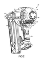
Figure 2 is a left rear perspective view of the battery powered tool ofFigure 1 ; -
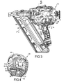
Figure 3 is a left side elevational view of the battery powered tool ofFigure 1 with the housing covers removed for clarity; -
Figure 4 is a left front perspective view of a rear housing cover for the battery powered tool ofFigure 1 ; -
Figure 5 is front elevational cross sectional view taken atsection 5 ofFigure 3 ; -
Figure 6 is a right rear perspective view of a motor assembly of the battery powered tool ofFigure 1 ; -
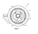
Figure 7 is a right elevational view of the motor assembly ofFigure 6 ; -
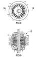
Figure 8 is a left elevational view of the motor assembly ofFigure 6 having the ventilation ducting removed for clarity; -
Figure 9 is a bottom plan cross sectional view taken at section 9 ofFigure 8 ; and -
Figure 10 is a bottom plan cross sectional view ofarea 10 ofFigure 9 . - Corresponding reference numerals indicate corresponding parts throughout the several views of the drawings.
- Referring to
Figure 1 , a battery poweredtool 10 can be, for example, a high powered cordless nailer. Battery poweredtool 10 includes ahousing 12 which incorporates components such as a motor and drive components connected to adrive portion 14 through which are ejectedfasteners 16. Thefasteners 16 can be temporarily stored in amagazine 18 which is connected to thedrive portion 14 and also supported at ahandle 20 used by an operator to manipulate the battery poweredtool 10. Atrigger 22 is manually depressed by the user to actuate operation of the battery poweredtool 10. Abattery 24 is releasably connected to thehandle 20 and provides operative electrical power for operation of battery poweredtool 10. - Battery powered
tool 10 provides acooling system 26 to limit the operating temperature of internal components of battery poweredtool 10. Included incooling system 26 are a plurality of ports or vents such asforward exhaust vents 28,rear exhaust vents 30, and at least one sidedischarge exhaust vent 32. The number and the discharge directions of exhaust vents is maximized to minimize backpressure, thereby providing a maximum exhaust flow of cooling air as will be described in greater detail in reference toFigure 3 . A rear of the battery poweredtool 10 is also the location for a plurality of intake vents which are principally provided in arear housing cover 34. - Referring to
Figure 2 , with therear housing cover 34 in its engaged position withhousing 12, a plurality offirst intake vents 36 and a plurality ofsecond intake vents 37 are created through therear housing cover 34 which permit an inflow of ambient air for operation of thecooling system 26 by drawing outside ambient temperature air inward at the rear of the tool and directing the ambient air in a forward direction toward thedrive portion 14. The initial components cooled by the ambient air are associated with anelectronics module 38, which can include ametal heat sink 39. A plurality ofthird intake vents 40 can also be provided which are created through arear housing portion 41 which is positioned proximate to and above thehandle 20 in a position which cannot be blocked when the operator's hand is engaged withhandle 20. - Referring to
Figure 3 and again toFigures 1-2 , with the cover ofhousing 12 and therear housing cover 34 removed for clarity, thecooling system 26 includes afan baffle 42 which exhausts air in multiple different directions to maximize the outflow of the now heated air.Electronics module 38 can further includemultiple bus capacitors 44. Theelectronics module 38 which controls multiple operations of battery operatedtool 10 is the first item convection cooled by the ambient air drawn in through the various intake vents prior to the air encountering the components of an electric motor. This ensures that the lowest temperature ambient air is provided to theelectronics module 38 before the air encounters any other components of the battery poweredtool 10. - The
fan baffle 42 is configured to provide multiple differently directed exhaust paths for the air flow to exit battery poweredtool 10. This minimizes the restriction of air exhausted by battery poweredtool 10. Thefan baffle 42 therefore includes afirst baffle exhaust 46 which directs air in a forward discharge direction "A". Asecond baffle exhaust 48 discharges air in a rear discharge direction "B". A third baffle exhaust 50 exhausts air in a side/upward discharge direction "C" as well as in a direction toward the viewer as shown inFigure 3 . Maximizing outlet flow from the first, second, andthird baffle exhausts upper housing space 52 ofhousing 12, thereby minimizing the amount of heated air which recirculates through battery poweredtool 10.Housing 12 further includes arib 54 at a rear portion of battery poweredtool 10. The purpose and function ofrib 54 will be described in better detail in reference toFigure 4 . - Referring to
Figure 4 and again toFigure 3 , as previously noted, therear housing cover 34 provides each of the first andsecond intake vents tool 10.Rear housing cover 34 also includes a first extendingwall 56 which is separated from a second extendingwall 58 by a width of therib 54 which extends fromhousing 12. When therear housing cover 34 is in its installed position,rib 54 is positioned between the first and second extendingwalls rear housing wall 60 from which the first and second extendingwalls Rib 54 is slidably received in ahorizontal slot 62 created between the first and second extendingwalls walls rib 54 in thehorizontal slot 62. The air seal substantially prevents ambient air drawn into the first and second intake vents 36, 37 from circulating into anupper housing zone 64 of therear housing cover 34. The ambient air is therefore constrained to flow only through a lower housing zone 66 of therear housing cover 34 and from there flows into a lower rear portion of the battery poweredtool 10. Because theelectronics module 38 is positioned proximate to the first and second intake vents 36, 37, ambient air is substantially forced to initially flow over theelectronics module 38 as it enters battery poweredtool 10. - Referring to
Figure 5 and again toFigure 3 ,tool 10 includes amotor assembly 68 which when energized rotates afan 72 with respect to astationary motor shaft 70. Thefan 72 defines a portion of coolingsystem 26 and provides the motive force for drawing air into therear housing cover 34, past theelectronics module 38, and then through internal areas ofmotor assembly 68 to coolmotor assembly 68, before being directly exhausted from battery poweredtool 10. Adrive wheel 74 is also rotated by themotor assembly 68 which is used to provide motive power for operation of thedrive portion 14. - Referring to
Figure 6 and again toFigures 1-5 ,motor assembly 68 also corotates each of thedrive wheel 74 and amotor end cap 76 which rotatably supportsdrive wheel 74 with respect tomotor shaft 70 with respect to abearing support 77. Thedrive wheel 74,end cap 76, andfan 72 co-rotate with respect to an axis ofrotation 78 defined through a longitudinal axis ofmotor shaft 70. Thedrive wheel 74 andend cap 76 continuously rotate during operation ofmotor assembly 68. To connect thedrive wheel 74 to theend cap 76, a plurality ofrib support members 80 are provided. Because air is also drawn intomotor assembly 68 between each of therib support members 80, therib support members 80 are shaped to minimize resistance to air flow as theend cap 76 rotates. Each of therib support members 80 therefore includes a convex curvedouter surface 82 and a concave curvedinner surface 84. The convex curvedouter surface 82 and concave curvedinner surface 84 merge to create each of aleading edge 86 and a trailingedge 88 of each of therib support members 80. Leading edge geometry minimizes high pressure at theleading edge 86, and the geometry of the trailingedge 88 minimizes boundary layer effects at the trailingedge 88. By reducing high pressure at the leading edge and minimizing the boundary layer effects at the trailing edge, the intake of air between the individualrib support members 80 is maximized. - The
third baffle exhaust 50 includes a curve-shapedduct portion 90 which is responsible for directing exhaust air out fromthird baffle exhaust 50 in each of the side upward discharge direction "C" as previously described, as well as in a horizontal discharge direction "D". By maximizing the different directions of discharge air coming from the various baffle exhausts, air flow into a plurality of intake vents 91 defined between successive ones of therib support members 80 is maximized, and the overall air flow throughtool 10 is maximized. - Referring to
Figure 7 and again toFigure 6 , multiple electronic components are mounted on a hall printed circuit board (PCB) 92 which is also supported by the structure ofmotor assembly 68. These include multipleelectronic components 94. In order to further maximize air flow through themotor assembly 68, thehall PCB 92 is reduced in size, permitting anair intake port 96 to be created inmotor assembly 68. Theair intake port 96 created throughhall PCB 92 extends over an intake port angular range "E" of approximately 130 degrees providing increased air flow throughmotor assembly 68. - Referring to
Figure 8 and again toFigures 6-7 , portions of thefan baffle 42 are removed for clarity such that features of thefan 72 are more readily visible. Multiplefan support members 97support fan 72.Fan 72 includes a plurality offan blades 98 whose body width axes are each axially aligned with the longitudinal axis defining the axis ofrotation 78 ofmotor shaft 70. Spaces between thefan support members 97 define individual fan intake vents 99. By minimizing the size/width and quantity of thefan support members 97, the volume of air that can be drawn into the fan intake vents 99 is increased. - Referring to
Figure 9 and again toFigure 8 , each of theindividual fan blades 98 are integrally connected to a circular ring/body 100 offan 72. The geometry of circular ring/body 100 is adapted to redirect air upwardly as viewed inFigure 9 and away from circular ring/body 100. This redirected air flow assists in forcing more of the air flow toward the exhaust vents, further minimizing the amount of back flow of the heated air recirculating intohousing 12 during operation ofmotor assembly 68. - Referring to
Figure 10 and again toFigures 8-9 , the circular ring/body 100 offan 72 includes an upwardly sloping, concave shapedsurface 102 which extends between a ringminimum height portion 104 proximate to a ringinner wall 106 to a ringmaximum height portion 108 positioned proximate to a ringouter wall 110. The function of concave shapedsurface 102 is to direct the air flow in a redirected air flow path "F" as the air contacts the concave shapedsurface 102. The redirected air flow path "F" moves the exhaust air upwardly and away fromfan 72 as viewed inFigure 10 . The advantage created by the geometry of concave shapedsurface 102 is that the air flow takes the redirected air flow path "F" in lieu of a non-redirected air flow path "G" which is oriented normal with respect to theindividual fan blades 98. Each of thefan blades 98 further includes an interiorrounded surface 112 and an exteriorrounded surface 114 which are blended into the geometry of concave shapedsurface 102. This blended geometry also reduces air turbulence at the junction between theindividual fan blades 98 and concave shapedsurface 102. - Referring generally to the figures, in an embodiment of a system and apparatus of a substantially sealed
cooling system 26 of fastening battery poweredtool 10, thecooling system 26 is sealed from the rest of the tool, in which fresh air is pulled across theelectronics module 38, through themotor assembly 68, into thefan 72 then out of thefan 72 and tool along a defined path in order to cool theelectronics module 38 andmotor assembly 68. Also, in an embodiment, a method for and apparatus defining an intake path for cooling air flow across theelectronics module 38 andmotor assembly 68 that includes exhausting heated air from the tool so that the heated air is prevented from blowing back into the tool. - Referring to generally to the figures, the battery powered
tool 10 mounts or integrates a fan on one side of the motor assembly 68 (left or assembly side in the example shown). Tool exhaust vents 28, 30, 32 are positioned on the same side, and the tool intake vents 36, 37, 40 are positioned at the rear of the tool. Themotor assembly 68 has the motor intake vents 91 on the opposite side of the fan 72 (the motor intake vents 91 are on the right side or cover side). The air flow paths are as follows. The air will come in through the rear tool intake vents 36, 37, 40, go across theelectronics module 38, go through the cover side motor intake vents 91, go through thefan 72; and exhaust out of the tool exhaust vents 28, 30, 32. Ribbing geometry is added to the module and the housing. This geometry serves two functions. The geometry forces all air to go across theelectronics module 38, and structurally supports theelectronics module 38 in the case of high shock or drop of the tool. - The
cooling system 26 limits the amount of air that can be pulled across theelectronics module 38 because themotor assembly 68 has restrictions in series with the electronics module restriction. In order to generate more cooling air flow across theelectronics module 38, a 2nd (lower restriction) intake asair intake port 96 is added to the motor baffle/hall PCB mount andhall PCB 92. In order to accomplish this, thehall PCB 92 has a substantially "U" shaped design. Although a higher motor temperature can result, themotor assembly 68 has a higher temperature limit and the amount of airflow through themotor assembly 68 drops less than 10% because thefan 72 is being "starved", therefore thefan 72 is more efficient as airflow volume increases. - To reduce recirculation back into the battery powered
tool 10, the following design is used. The exhaust side restriction is reduced by having, for example, three exhaust scrolls (baffle geometry) as exhaust vents 28, 30, 32 coming off of themotor fan 72. This design is able to achieve approximately 230 degrees of fan exhaust. The baffle overlaps the fan exhaust. For this, a "redirection ramp" as concave shapedsurface 102 is integrated on thefan 72. - The assembly side intake supports as
rib support members 80, for example 5 (five) in quantity each has an oval shape (in lieu of a rectangular geometry). In nonlimiting examples, an airfoil shape can be used for a single direction rotation; and the oval shape can be used for either directional operation. The aforementioned shapes are used primarily to reduce the pressure generated by the leadingedge 86 of therib support members 80. A rectangular geometry would act as a radial fan and generate high pressure regions. These high pressure regions would work against the intentional fan and significantly reduce airflow. The high pressure regions would also reduce the effective motor intake area. The aforementioned shapes are therefore used secondarily because the oval shaped supportrib support members 80 minimize the boundary layer on the trailingedge 88. By reducing the boundary layer, the effective motor intake increases. Any motor intake area gained at thestationary bearing support 77 is directly a gain in area because there are no rotational losses to be considered. - Several advantages provided by the
cooling system 26 of the battery poweredtool 10 include the following. Effective cooling of themotor assembly 68 and theelectronics module 38 is provided with themotor assembly 68 mounted perpendicular to theelectronics module 38. All cool intake air is directed across theelectronics module 38. Cooling of the system, particularly the electronics, is maximized by incorporating two separate intake vents for the motor fan 72 (airflow is increased greater than 200%). Integration of thefan exhaust baffle 42 and thehall PCB 92 mount reduces part count and motor size. Integration of thefan blade 98 geometry into themotor end cap 76 reduces part count and allows the fan intake to get bigger, thereby lowering intake restriction. Motor end cap support design ofrib support members 80 reduces the surface area of aleading edge 86 and thereby reduces a leading edge high pressure zone, and reduces a surface area of the trailingedge 88 thereby reducing a boundary layer at the trailingedge 88. - The
cooling system 26 of battery poweredtool 10 can: 1. Effectively cool themotor assembly 68 andelectronics module 38 for a high power (60A peak, 37A RMS fast rate, and 23A RMS continuous rate), with the cordless nailer or battery poweredtool 10 having themotor shaft 70 aligned perpendicular to theelectronics module 38; 2. Get more cooling airflow than what thefan 72 can pull through themotor assembly 68; 3. Reduce the exhaust air that can re-circulate back into the tool though a gap between the stationary baffle and the rotating fan/motor; and 4. Reduce the dynamic restriction of the motor and tool exhaust. - While aspects of the present invention are described herein and illustrated in the accompanying drawings in the context of a fastening tool, those of ordinary skill in the art will appreciate that the invention, in its broadest aspects, has further applicability. Example embodiments are provided so that this disclosure will be thorough, and will fully convey the scope to those who are skilled in the art. Numerous specific details are set forth such as examples of specific components, devices, and methods, to provide a thorough understanding of embodiments of the present disclosure. It will be apparent to those skilled in the art that specific details need not be employed, that example embodiments may be embodied in many different forms and that neither should be construed to limit the scope of the disclosure. In some example embodiments, well-known processes, well-known device structures, and well-known technologies are not described in detail.
- The terminology used herein is for the purpose of describing particular example embodiments only and is not intended to be limiting. As used herein, the singular forms "a," "an," and "the" may be intended to include the plural forms as well, unless the context clearly indicates otherwise. The terms "comprises," "comprising," "including," and "having," are inclusive and therefore specify the presence of stated features, integers, steps, operations, elements, and/or components, but do not preclude the presence or addition of one or more other features, integers, steps, operations, elements, components, and/or groups thereof. The method steps, processes, and operations described herein are not to be construed as necessarily requiring their performance in the particular order discussed or illustrated, unless specifically identified as an order of performance. It is also to be understood that additional or alternative steps may be employed.
- When an element or layer is referred to as being "on," "engaged to," "connected to," or "coupled to" another element or layer, it may be directly on, engaged, connected or coupled to the other element or layer, or intervening elements or layers may be present. In contrast, when an element is referred to as being "directly on," "directly engaged to," "directly connected to," or "directly coupled to" another element or layer, there may be no intervening elements or layers present. Other words used to describe the relationship between elements should be interpreted in a like fashion (e.g., "between" versus "directly between," "adjacent" versus "directly adjacent," etc.). As used herein, the term "and/or" includes any and all combinations of one or more of the associated listed items.
- Although the terms first, second, third, etc. may be used herein to describe various elements, components, regions, layers and/or sections, these elements, components, regions, layers and/or sections should not be limited by these terms. These terms may be only used to distinguish one element, component, region, layer or section from another region, layer or section. Terms such as "first," "second," and other numerical terms when used herein do not imply a sequence or order unless clearly indicated by the context. Thus, a first element, component, region, layer or section discussed below could be termed a second element, component, region, layer or section without departing from the teachings of the example embodiments.
- Spatially relative terms, such as "inner," "outer," "beneath," "below," "lower," "above," "upper," and the like, may be used herein for ease of description to describe one element or feature's relationship to another element(s) or feature(s) as illustrated in the figures. Spatially relative terms may be intended to encompass different orientations of the device in use or operation in addition to the orientation depicted in the figures. For example, if the device in the figures is turned over, elements described as "below" or "beneath" other elements or features would then be oriented "above" the other elements or features. Thus, the example term "below" can encompass both an orientation of above and below. The device may be otherwise oriented (rotated 90 degrees or at other orientations) and the spatially relative descriptors used herein interpreted accordingly.
- It will be appreciated that the above description is merely exemplary in nature and is not intended to limit the present disclosure, its application or uses. While specific examples have been described in the specification and illustrated in the drawings, it will be understood by those of ordinary skill in the art that various changes may be made and equivalents may be substituted for elements thereof without departing from the scope of the present disclosure. Furthermore, the mixing and matching of features, elements and/or functions between various examples is expressly contemplated herein, even if not specifically shown or described, so that one of ordinary skill in the art would appreciate from this disclosure that features, elements and/or functions of one example may be incorporated into another example as appropriate, unless described otherwise, above. Moreover, many modifications may be made to adapt a particular situation or material to the teachings of the present disclosure without departing from the essential scope thereof. Therefore, it is intended that the present disclosure not be limited to the particular examples illustrated by the drawings and described in the specification as the best mode presently contemplated for carrying out the teachings of the present disclosure, but that the scope of the present disclosure will include any embodiments falling within the foregoing description.
- The foregoing description of the embodiments has been provided for purposes of illustration and description. It is not intended to be exhaustive or to limit the disclosure. Individual elements or features of a particular embodiment are generally not limited to that particular embodiment, but, where applicable, are interchangeable and can be used in a selected embodiment, even if not specifically shown or described. The same may also be varied in many ways. Such variations are not to be regarded as a departure from the disclosure, and all such modifications are intended to be included within the scope of the disclosure.
Claims (15)
- A battery powered tool, comprising:a housing containing a motor assembly;a fan positioned in the housing and rotated by the motor assembly, the fan having a circular ring/body defining a concave shaped surface, and further having multiple fan blades directly connected to the concave shaped surface; anda fan baffle receiving air discharged by the fan blades, the fan baffle having at least two differently directed baffle exhausts.
- The battery powered tool of Claim 1, wherein the at least two differently directed baffle exhausts include a first baffle exhaust directed in a forward discharge direction and a second baffle exhaust directed in a rear discharge direction.
- The battery powered tool of Claim 2, wherein the at least two differently directed baffle exhausts include a third baffle exhaust directed in a side upward discharge direction.
- The battery powered tool of Claim 3, wherein the third baffle exhaust is further adapted to discharge in a side horizontal discharge direction.
- The battery powered tool of Claim 1, further including:a rib created in the housing; anda housing cover, including:first and second extending walls; anda slot created between the first and second extending walls sized to slidaby receive the rib.
- The battery powered tool of Claim 5, wherein the rib when received in the slot of the housing cover separates the housing cover into an upper housing zone and a lower housing zone.
- The battery powered tool of Claim 6, wherein the housing cover includes multiple intake vents receiving outside air during operation of the fan, the intake vents all located in the lower housing zone.
- The battery powered tool of Claim 1, wherein the battery powered tool comprises a cordless nailer having a magazine for retention and ejection of a plurality of fasteners.
- The battery powered tool of Claim 1, wherein the concave shaped surface extends from a ring minimum height portion proximate to a ring inner wall to a ring maximum height portion positioned proximate to a ring outer wall.
- A battery powered tool, comprising:a housing containing a motor assembly, including:a drive wheel;a support ring connected to the drive wheel and co-rotatable therewith; andmultiple rib support members connecting the support ring to the drive wheel, each having a leading edge and a trailing edge and further including:a convex curved outer surface; anda concave curved inner surface joining the convex curved outer surface at each of the leading edge and the trailing edge.
- The battery powered tool of Claim 10, further including a fan rotated by the motor assembly, the fan having a circular ring/body defining a concave shaped surface, and further having multiple fan blades directly connected to the concave shaped surface.
- The battery powered tool of Claim 11, wherein the leading edge acts to minimize a leading edge high pressure during fan operation, and the trailing edge acts to minimize a trailing edge boundary layer during operation of the fan.
- The battery powered tool of Claim 11, further including a fan baffle receiving air discharged by the fan blades, the fan baffle having three differently directed baffle exhausts.
- The battery powered tool of Claim 11, wherein the three differently directed baffle exhausts include:a first baffle exhaust directed in a forward discharge direction;a second baffle exhaust directed in a rear discharge direction; anda third baffle exhaust directed in a side upward discharge direction.
- The battery powered tool of Claim 11, further including a fan baffle wherein the fan baffle includes a hall PCB having an air intake port permitting inflow of air into the motor assembly through the air intake port.
Applications Claiming Priority (2)
| Application Number | Priority Date | Filing Date | Title |
|---|---|---|---|
| US201261703468P | 2012-09-20 | 2012-09-20 | |
| US13/840,015 US9577493B2 (en) | 2012-09-20 | 2013-03-15 | Motor and electronics cooling system for a high power cordless nailer |
Publications (3)
| Publication Number | Publication Date |
|---|---|
| EP2711140A2 true EP2711140A2 (en) | 2014-03-26 |
| EP2711140A3 EP2711140A3 (en) | 2018-02-14 |
| EP2711140B1 EP2711140B1 (en) | 2021-02-24 |
Family
ID=49083593
Family Applications (2)
| Application Number | Title | Priority Date | Filing Date |
|---|---|---|---|
| EP13182846.9A Active EP2711139B1 (en) | 2012-09-20 | 2013-09-03 | Motor and electronics cooling system for a high power cordless nailer |
| EP13182847.7A Active EP2711140B1 (en) | 2012-09-20 | 2013-09-03 | Motor and electronics cooling system for a high power cordless nailer |
Family Applications Before (1)
| Application Number | Title | Priority Date | Filing Date |
|---|---|---|---|
| EP13182846.9A Active EP2711139B1 (en) | 2012-09-20 | 2013-09-03 | Motor and electronics cooling system for a high power cordless nailer |
Country Status (2)
| Country | Link |
|---|---|
| US (1) | US9577493B2 (en) |
| EP (2) | EP2711139B1 (en) |
Families Citing this family (30)
| Publication number | Priority date | Publication date | Assignee | Title |
|---|---|---|---|---|
| TWI458603B (en) * | 2013-08-01 | 2014-11-01 | Basso Ind Corp | Power tools for heat dissipation devices |
| US10022848B2 (en) * | 2014-07-28 | 2018-07-17 | Black & Decker Inc. | Power tool drive mechanism |
| DE102014207867B4 (en) * | 2014-04-25 | 2025-06-26 | Robert Bosch Gmbh | Machine tool cooling device |
| US11325235B2 (en) | 2016-06-28 | 2022-05-10 | Black & Decker, Inc. | Push-on support member for fastening tools |
| US11267114B2 (en) | 2016-06-29 | 2022-03-08 | Black & Decker, Inc. | Single-motion magazine retention for fastening tools |
| US10987790B2 (en) | 2016-06-30 | 2021-04-27 | Black & Decker Inc. | Cordless concrete nailer with improved power take-off mechanism |
| US11279013B2 (en) | 2016-06-30 | 2022-03-22 | Black & Decker, Inc. | Driver rebound plate for a fastening tool |
| US11400572B2 (en) | 2016-06-30 | 2022-08-02 | Black & Decker, Inc. | Dry-fire bypass for a fastening tool |
| US10926385B2 (en) | 2017-02-24 | 2021-02-23 | Black & Decker, Inc. | Contact trip having magnetic filter |
| USD843803S1 (en) * | 2017-03-30 | 2019-03-26 | 7Rdd Limited | Cordless nailer |
| CN107147247A (en) * | 2017-04-28 | 2017-09-08 | 贾正刚 | A kind of energy-saving electric machine of convenient use |
| CN106953448A (en) * | 2017-04-28 | 2017-07-14 | 孙加红 | A kind of energy-saving motor with heat sinking function |
| US10840776B2 (en) | 2017-05-27 | 2020-11-17 | Actuator Electric Motors | Self-contained brushless motor and brushless controller |
| CN110170967B (en) | 2018-02-20 | 2023-03-21 | 美克司株式会社 | Driving tool |
| JP7259338B2 (en) * | 2018-02-20 | 2023-04-18 | マックス株式会社 | driving tool |
| CA3106685C (en) * | 2018-08-28 | 2023-12-05 | Kyocera Senco Industrial Tools, Inc. | Forced air cooling from piston movements of nailer tool |
| US10967492B2 (en) | 2018-11-19 | 2021-04-06 | Brahma Industries LLC | Staple gun with automatic depth adjustment |
| US10933521B2 (en) | 2018-11-19 | 2021-03-02 | Brahma Industries LLC | Staple gun with self-centering mechanism |
| US11141849B2 (en) | 2018-11-19 | 2021-10-12 | Brahma Industries LLC | Protective shield for use with a staple gun |
| JP7077922B2 (en) * | 2018-11-21 | 2022-05-31 | 工機ホールディングス株式会社 | Electrical equipment system |
| US11806854B2 (en) | 2019-02-19 | 2023-11-07 | Brahma Industries LLC | Insert for palm stapler, a palm stapler and a method of use thereof |
| US11973374B2 (en) | 2019-04-24 | 2024-04-30 | Black & Decker Inc. | Outer rotor brushless motor having an axial fan |
| USD911803S1 (en) * | 2019-06-12 | 2021-03-02 | Black & Decker, Inc. | Cordless roofing nailer |
| JP2023005814A (en) | 2021-06-29 | 2023-01-18 | 株式会社マキタ | electric work machine |
| JP7716245B2 (en) | 2021-06-29 | 2025-07-31 | 株式会社マキタ | electric work equipment |
| JP2023006092A (en) | 2021-06-30 | 2023-01-18 | 株式会社マキタ | electric work machine |
| US12489335B2 (en) * | 2022-06-27 | 2025-12-02 | Black & Decker Inc. | Power tool with enhanced air flow |
| US12368347B2 (en) | 2022-12-01 | 2025-07-22 | Norbar Torque Tools Limited | Cooling electronics of power tools |
| US20250010444A1 (en) * | 2023-07-06 | 2025-01-09 | Milwaukee Electric Tool Corporation | Powered fastener driver |
| TWI886869B (en) * | 2024-03-26 | 2025-06-11 | 力肯實業股份有限公司 | Rotary drive assembly for electric nail guns |
Family Cites Families (52)
| Publication number | Priority date | Publication date | Assignee | Title |
|---|---|---|---|---|
| US3694680A (en) | 1970-10-06 | 1972-09-26 | Murphy Ind Inc G W | Stamped shell sheet metal frame module for a power tool |
| US3978354A (en) | 1970-11-03 | 1976-08-31 | Rockwell International Corporation | Permanent magnet electrical machines |
| US3699366A (en) | 1971-06-07 | 1972-10-17 | Black & Decker Mfg Co | Power tool with motor support means |
| SE396171B (en) | 1975-12-17 | 1977-09-05 | Skf Ind Trading & Dev | COMMUTE ENGINE |
| US4219749A (en) | 1978-07-10 | 1980-08-26 | The Singer Company | Housing for power tools |
| US4295268A (en) | 1979-04-06 | 1981-10-20 | Emerson Electric Co. | Method of assembling an electric motor |
| US4384224A (en) | 1979-05-11 | 1983-05-17 | Koehring Company | Drive unit for flexshaft vibrators |
| US4342929A (en) | 1979-07-13 | 1982-08-03 | Black & Decker Inc. | Electric motor wherein low temperature polymeric housing supports heat dissipating portions through heat resisting polymeric bridging member |
| US4322647A (en) | 1979-11-23 | 1982-03-30 | The Scott & Fetzer Company | Motor assembly |
| US4583600A (en) | 1981-04-30 | 1986-04-22 | Black & Decker Inc. | Impact tool |
| US4449660A (en) | 1981-04-30 | 1984-05-22 | Black & Decker Inc. | Fastener tool |
| US4498230A (en) | 1982-01-08 | 1985-02-12 | Black & Decker Inc. | Assembling brush box sub-assemblies in electric motors |
| US4613781A (en) | 1983-09-09 | 1986-09-23 | Black & Decker Inc. | End cap assembly and brush box an electric motor |
| GB2186342A (en) | 1986-02-06 | 1987-08-12 | Johnson Electric Ind Mfg | An electric motor and gearbox unit and component parts thereof |
| US4746828A (en) | 1987-02-09 | 1988-05-24 | Electrolux Corporation | Molded electric motor housing and brush holder unit |
| US4800312A (en) | 1987-05-21 | 1989-01-24 | Shop-Vac Corporation | Mounting for brushes of electric motors |
| US5006740A (en) * | 1990-06-13 | 1991-04-09 | Milwaukee Electric Tool Corporation | Insulated cooling boot for power tool |
| FR2670961A1 (en) | 1990-12-21 | 1992-06-26 | Nivernais Ste Electronique | APPARATUS PROVIDED WITH AN ELECTRIC DRIVE MOTOR. |
| US5818142A (en) | 1995-07-27 | 1998-10-06 | Black & Decker Inc. | Motor pack armature support with brush holder assembly |
| US5814908A (en) * | 1996-04-30 | 1998-09-29 | Siemens Electric Limited | Blower wheel with axial inlet for ventilation |
| DE19631517A1 (en) * | 1996-08-03 | 1998-02-05 | Wacker Werke Kg | Variable-speed, hand-held power tool driven by an electric motor that can be connected to single-phase alternating current |
| DE29620393U1 (en) * | 1996-11-25 | 1998-03-26 | Robert Bosch Gmbh, 70469 Stuttgart | Hand tool |
| JP3794098B2 (en) * | 1997-01-31 | 2006-07-05 | 株式会社デンソー | Centrifugal blower |
| JP3676609B2 (en) * | 1998-09-29 | 2005-07-27 | 株式会社マキタ | Mounting structure of hanging tool in electric power tool |
| EP1024295A1 (en) * | 1999-01-27 | 2000-08-02 | Siemens Aktiengesellschaft | Electric motor drive |
| US7225959B2 (en) * | 2001-04-30 | 2007-06-05 | Black & Decker, Inc. | Portable, battery-powered air compressor for a pneumatic tool system |
| US6729414B2 (en) * | 2002-07-16 | 2004-05-04 | Black & Decker Inc. | Cordless drill with metal housing |
| US6724105B2 (en) * | 2002-09-10 | 2004-04-20 | Shi Hiu Chen | Dual-directionally operated dynamo set |
| US7653963B2 (en) | 2002-11-12 | 2010-02-02 | Black & Decker Inc. | AC/DC hand portable wet/dry vacuum having improved portability and convenience |
| DE10261572A1 (en) * | 2002-12-23 | 2004-07-01 | Robert Bosch Gmbh | Electric hand tool machine e.g. drill, has arrangement for generating additional cooling air flow that passes at least one machine component outside or in low flow region of cooling air flow |
| US20050113216A1 (en) * | 2003-10-07 | 2005-05-26 | Wei Cheng | Belt drive system with outer rotor motor |
| DE10347943B4 (en) * | 2003-10-15 | 2018-08-23 | Robert Bosch Gmbh | Power tool |
| US7303028B2 (en) * | 2004-03-18 | 2007-12-04 | Positec Power Tools (Suzhou) Co., Ltd. | Adjustable handle for a power tool |
| US8302833B2 (en) * | 2004-04-02 | 2012-11-06 | Black & Decker Inc. | Power take off for cordless nailer |
| DE102004029220B4 (en) * | 2004-06-16 | 2006-03-23 | Hilti Ag | Hand tool with dust extraction module |
| TWI300284B (en) * | 2005-04-18 | 2008-08-21 | Delta Electronics Inc | Heat-dissipation structure of motor |
| DE502005005887D1 (en) * | 2005-05-10 | 2008-12-18 | Siemens Ag | Electric machine |
| US7554228B2 (en) * | 2005-05-25 | 2009-06-30 | Hewlett-Packard Development Company, L.P. | Cooling fan with an outer rotor motor |
| WO2006131470A2 (en) * | 2005-06-06 | 2006-12-14 | Gebr. Becker Gmbh | Radial fan |
| DE102005049261B3 (en) * | 2005-10-14 | 2007-03-29 | Siemens Ag | Radiator fan for motor vehicle, has integrated fan motor, driving fan wheel, with inner rotor, where wheel has fan hub, which is directly connected with rotor, and hub has number of fan blades, which are arranged in two groups |
| DE102006000162A1 (en) * | 2006-04-06 | 2007-10-11 | Hilti Ag | Electric hand tool machine with internal cooling fan |
| DE102007000290A1 (en) * | 2007-05-24 | 2008-11-27 | Hilti Aktiengesellschaft | Electric hand tool with electronic cooling |
| DE102007000524A1 (en) * | 2007-10-18 | 2009-04-23 | Hilti Aktiengesellschaft | Electric hand tool machine with engine temperature control |
| US7770660B2 (en) * | 2007-11-21 | 2010-08-10 | Black & Decker Inc. | Mid-handle drill construction and assembly process |
| JP5309920B2 (en) * | 2008-11-19 | 2013-10-09 | 日立工機株式会社 | Electric tool |
| CN102388525B (en) * | 2009-01-24 | 2014-09-24 | 马夸特有限责任公司 | Regulators for electric motors |
| DE102009012177A1 (en) * | 2009-02-27 | 2010-09-02 | Andreas Stihl Ag & Co. Kg | Battery operated, handheld electrical appliance |
| EP2427954B1 (en) * | 2009-05-06 | 2014-03-05 | Munters Corporation | Fan for use in agriculture |
| US8039999B2 (en) * | 2009-06-26 | 2011-10-18 | Bach Pangho Chen | Heat dissipation structure for sealed machine tools |
| CN101941200B (en) * | 2009-07-03 | 2015-03-25 | 德昌电机(深圳)有限公司 | Electric tool and motor assembly thereof |
| US8760017B2 (en) * | 2010-07-05 | 2014-06-24 | Hanning Elektro-Werke Gmbh & Co. Kg | Electric machine |
| US8267673B1 (en) * | 2011-05-04 | 2012-09-18 | John Pairaktaridis | Brushless cooling fan |
-
2013
- 2013-03-15 US US13/840,015 patent/US9577493B2/en active Active
- 2013-09-03 EP EP13182846.9A patent/EP2711139B1/en active Active
- 2013-09-03 EP EP13182847.7A patent/EP2711140B1/en active Active
Non-Patent Citations (1)
| Title |
|---|
| None |
Also Published As
| Publication number | Publication date |
|---|---|
| EP2711139B1 (en) | 2020-09-02 |
| US20140076953A1 (en) | 2014-03-20 |
| US9577493B2 (en) | 2017-02-21 |
| EP2711140A3 (en) | 2018-02-14 |
| EP2711140B1 (en) | 2021-02-24 |
| EP2711139A2 (en) | 2014-03-26 |
| EP2711139A3 (en) | 2018-01-24 |
Similar Documents
| Publication | Publication Date | Title |
|---|---|---|
| EP2711140B1 (en) | Motor and electronics cooling system for a high power cordless nailer | |
| US10091954B1 (en) | Handheld blower | |
| US5417554A (en) | Air cooling system for scroll compressors | |
| US6379116B1 (en) | Impeller and structure for an impeller housing | |
| US20080290745A1 (en) | Electrical hand-held power tool with cooling of electronics | |
| US9138884B2 (en) | Handheld work apparatus | |
| US10000900B2 (en) | Handheld blower having engine cooling flow | |
| US8152495B2 (en) | Peripheral discharge tube axial fan | |
| EP2739835B1 (en) | Fan configuration for an engine driven generator | |
| EP1398864B1 (en) | Electric power tool | |
| CA2342682A1 (en) | Cooling air arrangement for a heat exchanger of an aircraft air conditioning unit | |
| EP2747949B1 (en) | Portable handheld power tool | |
| JP7366703B2 (en) | blower | |
| US10065219B2 (en) | Power-operated air propelling work apparatus | |
| EP2688801B1 (en) | Aircraft tail region with a cooling system installed in said aircraft tail region | |
| EP3651610B1 (en) | Hair dryer | |
| EP3540241B1 (en) | A transport refrigeration unit with a labyrinth seal for a fan assembly | |
| GB2423420A (en) | Device for cooling the control electronics of a power tool | |
| EP1584423A2 (en) | Power tool | |
| CN211270282U (en) | Food preparation machine with good heat dissipation | |
| CN218449709U (en) | Forward and reverse rotation brushless motor | |
| US20120152504A1 (en) | Handheld power tool with air-guiding element | |
| US12558730B2 (en) | Work machine | |
| CN213655199U (en) | Blower fan | |
| CN219780739U (en) | Automobile controller |
Legal Events
| Date | Code | Title | Description |
|---|---|---|---|
| PUAI | Public reference made under article 153(3) epc to a published international application that has entered the european phase |
Free format text: ORIGINAL CODE: 0009012 |
|
| AK | Designated contracting states |
Kind code of ref document: A2 Designated state(s): AL AT BE BG CH CY CZ DE DK EE ES FI FR GB GR HR HU IE IS IT LI LT LU LV MC MK MT NL NO PL PT RO RS SE SI SK SM TR |
|
| AX | Request for extension of the european patent |
Extension state: BA ME |
|
| PUAL | Search report despatched |
Free format text: ORIGINAL CODE: 0009013 |
|
| AK | Designated contracting states |
Kind code of ref document: A3 Designated state(s): AL AT BE BG CH CY CZ DE DK EE ES FI FR GB GR HR HU IE IS IT LI LT LU LV MC MK MT NL NO PL PT RO RS SE SI SK SM TR |
|
| AX | Request for extension of the european patent |
Extension state: BA ME |
|
| RIC1 | Information provided on ipc code assigned before grant |
Ipc: B25F 5/00 20060101AFI20180110BHEP |
|
| STAA | Information on the status of an ep patent application or granted ep patent |
Free format text: STATUS: REQUEST FOR EXAMINATION WAS MADE |
|
| 17P | Request for examination filed |
Effective date: 20180813 |
|
| RBV | Designated contracting states (corrected) |
Designated state(s): AL AT BE BG CH CY CZ DE DK EE ES FI FR GB GR HR HU IE IS IT LI LT LU LV MC MK MT NL NO PL PT RO RS SE SI SK SM TR |
|
| GRAP | Despatch of communication of intention to grant a patent |
Free format text: ORIGINAL CODE: EPIDOSNIGR1 |
|
| STAA | Information on the status of an ep patent application or granted ep patent |
Free format text: STATUS: GRANT OF PATENT IS INTENDED |
|
| INTG | Intention to grant announced |
Effective date: 20200422 |
|
| GRAJ | Information related to disapproval of communication of intention to grant by the applicant or resumption of examination proceedings by the epo deleted |
Free format text: ORIGINAL CODE: EPIDOSDIGR1 |
|
| STAA | Information on the status of an ep patent application or granted ep patent |
Free format text: STATUS: REQUEST FOR EXAMINATION WAS MADE |
|
| INTC | Intention to grant announced (deleted) | ||
| GRAS | Grant fee paid |
Free format text: ORIGINAL CODE: EPIDOSNIGR3 |
|
| STAA | Information on the status of an ep patent application or granted ep patent |
Free format text: STATUS: GRANT OF PATENT IS INTENDED |
|
| GRAP | Despatch of communication of intention to grant a patent |
Free format text: ORIGINAL CODE: EPIDOSNIGR1 |
|
| INTG | Intention to grant announced |
Effective date: 20201009 |
|
| GRAF | Information related to payment of grant fee modified |
Free format text: ORIGINAL CODE: EPIDOSCIGR3 |
|
| GRAA | (expected) grant |
Free format text: ORIGINAL CODE: 0009210 |
|
| STAA | Information on the status of an ep patent application or granted ep patent |
Free format text: STATUS: THE PATENT HAS BEEN GRANTED |
|
| AK | Designated contracting states |
Kind code of ref document: B1 Designated state(s): AL AT BE BG CH CY CZ DE DK EE ES FI FR GB GR HR HU IE IS IT LI LT LU LV MC MK MT NL NO PL PT RO RS SE SI SK SM TR |
|
| REG | Reference to a national code |
Ref country code: GB Ref legal event code: FG4D |
|
| REG | Reference to a national code |
Ref country code: CH Ref legal event code: EP |
|
| REG | Reference to a national code |
Ref country code: AT Ref legal event code: REF Ref document number: 1363856 Country of ref document: AT Kind code of ref document: T Effective date: 20210315 |
|
| REG | Reference to a national code |
Ref country code: IE Ref legal event code: FG4D |
|
| REG | Reference to a national code |
Ref country code: DE Ref legal event code: R096 Ref document number: 602013075821 Country of ref document: DE |
|
| REG | Reference to a national code |
Ref country code: LT Ref legal event code: MG9D |
|
| REG | Reference to a national code |
Ref country code: NL Ref legal event code: MP Effective date: 20210224 |
|
| PG25 | Lapsed in a contracting state [announced via postgrant information from national office to epo] |
Ref country code: BG Free format text: LAPSE BECAUSE OF FAILURE TO SUBMIT A TRANSLATION OF THE DESCRIPTION OR TO PAY THE FEE WITHIN THE PRESCRIBED TIME-LIMIT Effective date: 20210524 Ref country code: NO Free format text: LAPSE BECAUSE OF FAILURE TO SUBMIT A TRANSLATION OF THE DESCRIPTION OR TO PAY THE FEE WITHIN THE PRESCRIBED TIME-LIMIT Effective date: 20210524 Ref country code: LT Free format text: LAPSE BECAUSE OF FAILURE TO SUBMIT A TRANSLATION OF THE DESCRIPTION OR TO PAY THE FEE WITHIN THE PRESCRIBED TIME-LIMIT Effective date: 20210224 Ref country code: PT Free format text: LAPSE BECAUSE OF FAILURE TO SUBMIT A TRANSLATION OF THE DESCRIPTION OR TO PAY THE FEE WITHIN THE PRESCRIBED TIME-LIMIT Effective date: 20210624 Ref country code: GR Free format text: LAPSE BECAUSE OF FAILURE TO SUBMIT A TRANSLATION OF THE DESCRIPTION OR TO PAY THE FEE WITHIN THE PRESCRIBED TIME-LIMIT Effective date: 20210525 Ref country code: FI Free format text: LAPSE BECAUSE OF FAILURE TO SUBMIT A TRANSLATION OF THE DESCRIPTION OR TO PAY THE FEE WITHIN THE PRESCRIBED TIME-LIMIT Effective date: 20210224 Ref country code: HR Free format text: LAPSE BECAUSE OF FAILURE TO SUBMIT A TRANSLATION OF THE DESCRIPTION OR TO PAY THE FEE WITHIN THE PRESCRIBED TIME-LIMIT Effective date: 20210224 |
|
| REG | Reference to a national code |
Ref country code: AT Ref legal event code: MK05 Ref document number: 1363856 Country of ref document: AT Kind code of ref document: T Effective date: 20210224 |
|
| PG25 | Lapsed in a contracting state [announced via postgrant information from national office to epo] |
Ref country code: RS Free format text: LAPSE BECAUSE OF FAILURE TO SUBMIT A TRANSLATION OF THE DESCRIPTION OR TO PAY THE FEE WITHIN THE PRESCRIBED TIME-LIMIT Effective date: 20210224 Ref country code: PL Free format text: LAPSE BECAUSE OF FAILURE TO SUBMIT A TRANSLATION OF THE DESCRIPTION OR TO PAY THE FEE WITHIN THE PRESCRIBED TIME-LIMIT Effective date: 20210224 Ref country code: NL Free format text: LAPSE BECAUSE OF FAILURE TO SUBMIT A TRANSLATION OF THE DESCRIPTION OR TO PAY THE FEE WITHIN THE PRESCRIBED TIME-LIMIT Effective date: 20210224 Ref country code: LV Free format text: LAPSE BECAUSE OF FAILURE TO SUBMIT A TRANSLATION OF THE DESCRIPTION OR TO PAY THE FEE WITHIN THE PRESCRIBED TIME-LIMIT Effective date: 20210224 Ref country code: SE Free format text: LAPSE BECAUSE OF FAILURE TO SUBMIT A TRANSLATION OF THE DESCRIPTION OR TO PAY THE FEE WITHIN THE PRESCRIBED TIME-LIMIT Effective date: 20210224 |
|
| PG25 | Lapsed in a contracting state [announced via postgrant information from national office to epo] |
Ref country code: IS Free format text: LAPSE BECAUSE OF FAILURE TO SUBMIT A TRANSLATION OF THE DESCRIPTION OR TO PAY THE FEE WITHIN THE PRESCRIBED TIME-LIMIT Effective date: 20210624 |
|
| PG25 | Lapsed in a contracting state [announced via postgrant information from national office to epo] |
Ref country code: CZ Free format text: LAPSE BECAUSE OF FAILURE TO SUBMIT A TRANSLATION OF THE DESCRIPTION OR TO PAY THE FEE WITHIN THE PRESCRIBED TIME-LIMIT Effective date: 20210224 Ref country code: EE Free format text: LAPSE BECAUSE OF FAILURE TO SUBMIT A TRANSLATION OF THE DESCRIPTION OR TO PAY THE FEE WITHIN THE PRESCRIBED TIME-LIMIT Effective date: 20210224 Ref country code: SM Free format text: LAPSE BECAUSE OF FAILURE TO SUBMIT A TRANSLATION OF THE DESCRIPTION OR TO PAY THE FEE WITHIN THE PRESCRIBED TIME-LIMIT Effective date: 20210224 Ref country code: AT Free format text: LAPSE BECAUSE OF FAILURE TO SUBMIT A TRANSLATION OF THE DESCRIPTION OR TO PAY THE FEE WITHIN THE PRESCRIBED TIME-LIMIT Effective date: 20210224 |
|
| REG | Reference to a national code |
Ref country code: DE Ref legal event code: R097 Ref document number: 602013075821 Country of ref document: DE |
|
| PG25 | Lapsed in a contracting state [announced via postgrant information from national office to epo] |
Ref country code: RO Free format text: LAPSE BECAUSE OF FAILURE TO SUBMIT A TRANSLATION OF THE DESCRIPTION OR TO PAY THE FEE WITHIN THE PRESCRIBED TIME-LIMIT Effective date: 20210224 Ref country code: DK Free format text: LAPSE BECAUSE OF FAILURE TO SUBMIT A TRANSLATION OF THE DESCRIPTION OR TO PAY THE FEE WITHIN THE PRESCRIBED TIME-LIMIT Effective date: 20210224 Ref country code: ES Free format text: LAPSE BECAUSE OF FAILURE TO SUBMIT A TRANSLATION OF THE DESCRIPTION OR TO PAY THE FEE WITHIN THE PRESCRIBED TIME-LIMIT Effective date: 20210224 Ref country code: SK Free format text: LAPSE BECAUSE OF FAILURE TO SUBMIT A TRANSLATION OF THE DESCRIPTION OR TO PAY THE FEE WITHIN THE PRESCRIBED TIME-LIMIT Effective date: 20210224 |
|
| PLBE | No opposition filed within time limit |
Free format text: ORIGINAL CODE: 0009261 |
|
| STAA | Information on the status of an ep patent application or granted ep patent |
Free format text: STATUS: NO OPPOSITION FILED WITHIN TIME LIMIT |
|
| PG25 | Lapsed in a contracting state [announced via postgrant information from national office to epo] |
Ref country code: AL Free format text: LAPSE BECAUSE OF FAILURE TO SUBMIT A TRANSLATION OF THE DESCRIPTION OR TO PAY THE FEE WITHIN THE PRESCRIBED TIME-LIMIT Effective date: 20210224 |
|
| 26N | No opposition filed |
Effective date: 20211125 |
|
| PG25 | Lapsed in a contracting state [announced via postgrant information from national office to epo] |
Ref country code: SI Free format text: LAPSE BECAUSE OF FAILURE TO SUBMIT A TRANSLATION OF THE DESCRIPTION OR TO PAY THE FEE WITHIN THE PRESCRIBED TIME-LIMIT Effective date: 20210224 |
|
| PG25 | Lapsed in a contracting state [announced via postgrant information from national office to epo] |
Ref country code: IT Free format text: LAPSE BECAUSE OF FAILURE TO SUBMIT A TRANSLATION OF THE DESCRIPTION OR TO PAY THE FEE WITHIN THE PRESCRIBED TIME-LIMIT Effective date: 20210224 |
|
| REG | Reference to a national code |
Ref country code: CH Ref legal event code: PL |
|
| REG | Reference to a national code |
Ref country code: BE Ref legal event code: MM Effective date: 20210930 |
|
| PG25 | Lapsed in a contracting state [announced via postgrant information from national office to epo] |
Ref country code: IS Free format text: LAPSE BECAUSE OF FAILURE TO SUBMIT A TRANSLATION OF THE DESCRIPTION OR TO PAY THE FEE WITHIN THE PRESCRIBED TIME-LIMIT Effective date: 20210624 Ref country code: MC Free format text: LAPSE BECAUSE OF FAILURE TO SUBMIT A TRANSLATION OF THE DESCRIPTION OR TO PAY THE FEE WITHIN THE PRESCRIBED TIME-LIMIT Effective date: 20210224 |
|
| PG25 | Lapsed in a contracting state [announced via postgrant information from national office to epo] |
Ref country code: LU Free format text: LAPSE BECAUSE OF NON-PAYMENT OF DUE FEES Effective date: 20210903 Ref country code: IE Free format text: LAPSE BECAUSE OF NON-PAYMENT OF DUE FEES Effective date: 20210903 Ref country code: FR Free format text: LAPSE BECAUSE OF NON-PAYMENT OF DUE FEES Effective date: 20210930 Ref country code: BE Free format text: LAPSE BECAUSE OF NON-PAYMENT OF DUE FEES Effective date: 20210930 |
|
| PG25 | Lapsed in a contracting state [announced via postgrant information from national office to epo] |
Ref country code: LI Free format text: LAPSE BECAUSE OF NON-PAYMENT OF DUE FEES Effective date: 20210930 Ref country code: CH Free format text: LAPSE BECAUSE OF NON-PAYMENT OF DUE FEES Effective date: 20210930 |
|
| PG25 | Lapsed in a contracting state [announced via postgrant information from national office to epo] |
Ref country code: HU Free format text: LAPSE BECAUSE OF FAILURE TO SUBMIT A TRANSLATION OF THE DESCRIPTION OR TO PAY THE FEE WITHIN THE PRESCRIBED TIME-LIMIT; INVALID AB INITIO Effective date: 20130903 |
|
| PG25 | Lapsed in a contracting state [announced via postgrant information from national office to epo] |
Ref country code: CY Free format text: LAPSE BECAUSE OF FAILURE TO SUBMIT A TRANSLATION OF THE DESCRIPTION OR TO PAY THE FEE WITHIN THE PRESCRIBED TIME-LIMIT Effective date: 20210224 |
|
| PG25 | Lapsed in a contracting state [announced via postgrant information from national office to epo] |
Ref country code: MK Free format text: LAPSE BECAUSE OF FAILURE TO SUBMIT A TRANSLATION OF THE DESCRIPTION OR TO PAY THE FEE WITHIN THE PRESCRIBED TIME-LIMIT Effective date: 20210224 |
|
| PG25 | Lapsed in a contracting state [announced via postgrant information from national office to epo] |
Ref country code: MT Free format text: LAPSE BECAUSE OF FAILURE TO SUBMIT A TRANSLATION OF THE DESCRIPTION OR TO PAY THE FEE WITHIN THE PRESCRIBED TIME-LIMIT Effective date: 20210224 |
|
| PGFP | Annual fee paid to national office [announced via postgrant information from national office to epo] |
Ref country code: DE Payment date: 20250919 Year of fee payment: 13 |
|
| PGFP | Annual fee paid to national office [announced via postgrant information from national office to epo] |
Ref country code: GB Payment date: 20250923 Year of fee payment: 13 |
|
| PG25 | Lapsed in a contracting state [announced via postgrant information from national office to epo] |
Ref country code: TR Free format text: LAPSE BECAUSE OF FAILURE TO SUBMIT A TRANSLATION OF THE DESCRIPTION OR TO PAY THE FEE WITHIN THE PRESCRIBED TIME-LIMIT Effective date: 20210224 |