EP2711068A1 - Co2 recovery device - Google Patents
Co2 recovery device Download PDFInfo
- Publication number
- EP2711068A1 EP2711068A1 EP12771068.9A EP12771068A EP2711068A1 EP 2711068 A1 EP2711068 A1 EP 2711068A1 EP 12771068 A EP12771068 A EP 12771068A EP 2711068 A1 EP2711068 A1 EP 2711068A1
- Authority
- EP
- European Patent Office
- Prior art keywords
- absorber
- flue gas
- absorbing unit
- cocurrent flow
- countercurrent
- Prior art date
- Legal status (The legal status is an assumption and is not a legal conclusion. Google has not performed a legal analysis and makes no representation as to the accuracy of the status listed.)
- Granted
Links
Images




Classifications
-
- B—PERFORMING OPERATIONS; TRANSPORTING
- B01—PHYSICAL OR CHEMICAL PROCESSES OR APPARATUS IN GENERAL
- B01D—SEPARATION
- B01D53/00—Separation of gases or vapours; Recovering vapours of volatile solvents from gases; Chemical or biological purification of waste gases, e.g. engine exhaust gases, smoke, fumes, flue gases, aerosols
- B01D53/14—Separation of gases or vapours; Recovering vapours of volatile solvents from gases; Chemical or biological purification of waste gases, e.g. engine exhaust gases, smoke, fumes, flue gases, aerosols by absorption
- B01D53/1425—Regeneration of liquid absorbents
-
- B—PERFORMING OPERATIONS; TRANSPORTING
- B01—PHYSICAL OR CHEMICAL PROCESSES OR APPARATUS IN GENERAL
- B01D—SEPARATION
- B01D53/00—Separation of gases or vapours; Recovering vapours of volatile solvents from gases; Chemical or biological purification of waste gases, e.g. engine exhaust gases, smoke, fumes, flue gases, aerosols
- B01D53/14—Separation of gases or vapours; Recovering vapours of volatile solvents from gases; Chemical or biological purification of waste gases, e.g. engine exhaust gases, smoke, fumes, flue gases, aerosols by absorption
- B01D53/1406—Multiple stage absorption
-
- B—PERFORMING OPERATIONS; TRANSPORTING
- B01—PHYSICAL OR CHEMICAL PROCESSES OR APPARATUS IN GENERAL
- B01D—SEPARATION
- B01D53/00—Separation of gases or vapours; Recovering vapours of volatile solvents from gases; Chemical or biological purification of waste gases, e.g. engine exhaust gases, smoke, fumes, flue gases, aerosols
- B01D53/14—Separation of gases or vapours; Recovering vapours of volatile solvents from gases; Chemical or biological purification of waste gases, e.g. engine exhaust gases, smoke, fumes, flue gases, aerosols by absorption
- B01D53/1456—Removing acid components
- B01D53/1475—Removing carbon dioxide
-
- B—PERFORMING OPERATIONS; TRANSPORTING
- B01—PHYSICAL OR CHEMICAL PROCESSES OR APPARATUS IN GENERAL
- B01D—SEPARATION
- B01D2252/00—Absorbents, i.e. solvents and liquid materials for gas absorption
- B01D2252/20—Organic absorbents
- B01D2252/204—Amines
-
- B—PERFORMING OPERATIONS; TRANSPORTING
- B01—PHYSICAL OR CHEMICAL PROCESSES OR APPARATUS IN GENERAL
- B01D—SEPARATION
- B01D2257/00—Components to be removed
- B01D2257/50—Carbon oxides
- B01D2257/504—Carbon dioxide
-
- B—PERFORMING OPERATIONS; TRANSPORTING
- B01—PHYSICAL OR CHEMICAL PROCESSES OR APPARATUS IN GENERAL
- B01D—SEPARATION
- B01D2258/00—Sources of waste gases
- B01D2258/02—Other waste gases
- B01D2258/0283—Flue gases
-
- Y—GENERAL TAGGING OF NEW TECHNOLOGICAL DEVELOPMENTS; GENERAL TAGGING OF CROSS-SECTIONAL TECHNOLOGIES SPANNING OVER SEVERAL SECTIONS OF THE IPC; TECHNICAL SUBJECTS COVERED BY FORMER USPC CROSS-REFERENCE ART COLLECTIONS [XRACs] AND DIGESTS
- Y02—TECHNOLOGIES OR APPLICATIONS FOR MITIGATION OR ADAPTATION AGAINST CLIMATE CHANGE
- Y02C—CAPTURE, STORAGE, SEQUESTRATION OR DISPOSAL OF GREENHOUSE GASES [GHG]
- Y02C20/00—Capture or disposal of greenhouse gases
- Y02C20/40—Capture or disposal of greenhouse gases of CO2
Definitions
- the present invention relates to a CO 2 recovery device that absorbs CO 2 contained in flue gas.
- Flue gas which is generated through the combustion of fossil fuel in a boiler of a thermoelectric power plant or the like using a large amount of fossil fuel, contains CO 2 .
- a method of removing and recovering CO 2 , which is contained in flue gas, by bringing flue gas, which contains CO 2 , into gas-liquid contact with an amine-based CO 2 absorbent in a CO 2 absorber so that CO 2 is absorbed in the CO 2 absorbent, and a method of storing the recovered CO 2 without releasing the recovered CO 2 into the atmosphere have been energetically studied.
- the CO 2 absorbent absorbent absorb CO 2 , which is contained in the flue gas, in the CO 2 absorber to remove CO 2 from the flue gas, regenerating the CO 2 absorbent by releasing CO 2 , which is absorbed in the CO 2 absorbent, in a regenerator, and reusing the CO 2 absorbent to remove CO 2 from flue gas by circulating the CO 2 absorbent in the CO 2 absorber again (for example, see Patent Literature 1).
- the CO 2 absorbent absorbing CO 2 releases CO 2 by being heated with steam in the regenerator. As a result, highly-pure CO 2 is recovered.
- Patent Literature 1 Japanese Laid-open Patent Publication NO. 2008-62165
- a CO 2 recovery device which uses a method of absorbing, removing, and recovering CO 2 from gas, which contains CO 2 , such as flue gas, by using a CO 2 absorbent, is additionally installed on a combustion facility
- the operating cost of the CO 2 recovery device should be reduced as much as possible. In particular, much thermal energy is consumed for the release of CO 2 in a regenerator of the CO 2 recovery device. Further, if the consumption of the CO 2 absorbent is large, the amount of a CO 2 absorbent to be additionally supplied is increased. Accordingly, the increase of operating cost is caused.
- the invention has been made in consideration of the above-mentioned circumstances, and an object of the invention is to provide a CO 2 recovery device that efficiently recovers CO 2 , reduces the consumption of a CO 2 absorbent, and reduces operating cost.
- a CO 2 recovery device including:
- the CO 2 recovery device according to the first aspect, wherein the CO 2 absorbent having absorbed CO 2 is cooled in the CO 2 -absorbing unit, and is supplied to the CO 2 -absorbing unit again.
- the CO 2 recovery device according to the first or second aspect, wherein the cocurrent flow CO 2 -absorbing unit is provided on the most upstream side in a flow direction of the flue gas.
- the CO 2 recovery device according to any one of the first to third aspects, wherein the countercurrent CO 2 -absorbing unit is provided on the most upstream side in the flow direction of the flue gas.
- the CO 2 recovery device according to any one of the first to fourth aspects, wherein at least one of the countercurrent CO 2 -absorbing unit and the cocurrent flow CO 2 -absorbing unit, which are included in the CO 2 -absorbing unit, is provided in a CO 2 absorber for bringing the flue gas into contact with the CO 2 absorbent so as to remove CO 2 from the flue gas, and the cocurrent flow CO 2 -absorbing unit is provided between the cooling unit and the CO 2 absorber.
- the CO 2 recovery device according to any one of the first to fifth aspects, wherein at least one of the countercurrent CO 2 -absorbing unit and the cocurrent flow CO 2 -absorbing unit, which are included in the CO 2 -absorbing unit, is provided in the CO 2 absorber for bringing the flue gas into contact with the CO 2 absorbent so as to remove CO 2 from the flue gas, and the countercurrent CO 2 -absorbing unit is provided between the cooling unit and the CO 2 absorber.
- the CO 2 recovery device according to any one of the first to sixth aspects, wherein the cooling unit is provided in a cooling tower for bringing the flue gas into contact with water so as to cool the flue gas, and the countercurrent CO 2 absorber is provided in the cooling tower.
- the CO 2 recovery device of the invention it is possible to efficiently recover CO 2 , to reduce the consumption of a CO 2 absorbent, and to reduce operating cost.
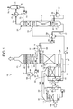
- FIG. 1 is a diagram simply illustrating the structure of a CO 2 recovery device according to the first embodiment of the invention.
- the CO 2 recovery device 10 includes a cooling unit 11, a CO 2 -absorbing unit 12, and an absorbent regenerating unit 13.
- the cooling unit 11 cools flue gas 14A by bringing the flue gas 14A containing CO 2 into contact with water 15, and is provided in a cooling tower 16.
- the CO 2 -absorbing unit 12 removes CO 2 from flue gas 14B by bringing the flue gas 14B into contact with a CO 2 absorbent (lean solution) 17 which absorbs CO 2 .
- the CO 2 -absorbing unit 12 includes a cocurrent flow CO 2 -absorbing unit 19 that removes CO 2 from the flue gas 14B by bringing the flue gas 14B into contact with a CO 2 absorbent (semi-rich solution) 24, which has absorbed CO 2 , in a cocurrent flow, and a countercurrent CO 2 -absorbing unit 20 that removes CO 2 from flue gas 14C by bringing the flue gas 14C into contact with the CO 2 absorbent 17 in a countercurrent flow.
- the absorbent regenerating unit 13 regenerates the CO 2 absorbent 17 by releasing CO 2 from a rich solution 18, and is provided in an absorbent regenerator (hereinafter, referred to as a regenerator) 21.
- the cocurrent flow CO 2 -absorbing unit 19 is provided in a cocurrent flow CO 2 absorber 22 and the countercurrent CO 2 -absorbing unit 20 is provided in a CO 2 absorber 23.
- the CO 2 -absorbing unit 12 includes one cocurrent flow CO 2 -absorbing unit 19 and one countercurrent CO 2 -absorbing unit 20.
- the CO 2 -absorbing unit 12 may include a plurality of cocurrent flow CO 2 -absorbing units 19 and one countercurrent CO 2 -absorbing unit 20, may include one cocurrent flow CO 2 -absorbing unit 19 and a plurality of countercurrent CO 2 -absorbing units 20, or may include a plurality of cocurrent flow CO 2 -absorbing units 19 and a plurality of countercurrent CO 2 -absorbing units 20.
- the rich solution 18, which has absorbed CO 2 contained in the flue gas 14B is fed to the regenerator 21 from the cocurrent flow CO 2 absorber 22.
- the CO 2 absorbent (lean solution) 17, which is regenerated by removing almost all of CO 2 from the rich solution 18 in the regenerator 21, is fed to the CO 2 absorber 23 from the regenerator 21.
- the flue gas 14A is gas that contains CO 2 discharged from industrial equipment, such as a boiler or a gas turbine. After the pressure of the flue gas 14A is increased by a flue gas blower or the like, the flue gas 14A is sent to the cooling tower 16.
- the cooling tower 16 is a tower that cools the flue gas 14A by water 15.
- the cooling tower 16 includes spray nozzles 26 that spray the water 15 into the tower, and a cooling unit 11.
- the flue gas 14A is cooled by coming into counterflow contact with the water 15 sprayed from the spray nozzles 26 in the cooling unit 11 of the cooling tower 16.
- the water 15 of which the temperature has become high by the heat exchange between the water 15 and the flue gas 14A is stored in the bottom of the cooling tower 16.
- the water 15 stored in the bottom of the cooling tower 16 is extracted from the bottom of the cooling tower 16, and is cooled by exchanging heat with cooling water 28 in a cooler 27. Then, the water 15 is fed to the cooling tower 16. Accordingly, the water 15 is circulated and used to cool the flue gas 14A.
- the cooled flue gas 14B is discharged from the cooling tower 16 through a flue gas duct 29 that connects the cooling tower 16 to the CO 2 absorber 23, and is fed to the CO 2 -absorbing unit 12.
- the CO 2 -absorbing unit 12 includes the cocurrent flow CO 2 -absorbing unit 19 and the countercurrent CO 2 -absorbing unit 20.
- the flue gas 14B is fed to the cocurrent flow CO 2 absorber 22 including the cocurrent flow CO 2 -absorbing unit 19 and the CO 2 absorber 23 including the countercurrent CO 2 -absorbing unit 20 in this order.
- the cocurrent flow CO 2 absorber 22 is provided between the cooling tower 16 including the cooling unit 11 and the CO 2 absorber 23.
- the cocurrent flow CO 2 absorber 22 including the cocurrent flow CO 2 -absorbing unit 19 is provided on the most upstream side in the flow direction of the flue gas 14B flowing in the CO 2 -absorbing unit 12.
- the flue gas 14B discharged from the cooling tower 16 is fed to the cocurrent flow CO 2 absorber 22 through the flue gas duct 29.
- the cocurrent flow CO 2 absorber 22 is a tower that removes CO 2 from the flue gas 14B by bringing the flue gas 14B into contact with the semi-rich solution 24, which is discharged from the CO 2 absorber 23, in a cocurrent flow.
- the cocurrent flow CO 2 absorber 22 includes spray nozzles 31 and the cocurrent flow CO 2 -absorbing unit 19 that are provided in the tower.
- the spray nozzles 31 spray the semi-rich solution 24 downward.
- the semi-rich solution 24 is discharged from the CO 2 absorber 23 through a semi-rich solution extraction line 32 and is cooled by exchanging heat with cooling water 34 in a cooler 33, the semi-rich solution 24 is fed to the cocurrent flow CO 2 absorber 22.
- the flue gas 14B is supplied from the top of the cocurrent flow CO 2 absorber 22, and flows in the tower toward the bottom of the tower.
- the semi-rich solution 24 since the semi-rich solution 24 is cooled before being supplied into the cocurrent flow CO 2 absorber 22, the semi-rich solution 24 can further absorb CO 2 , which is contained in the flue gas 14B, in the cocurrent flow CO 2 absorber 22. Therefore, it is possible to increase the concentration of CO 2 contained in the rich solution 18 that is stored in the bottom of the cocurrent flow CO 2 absorber 22.
- the semi-rich solution 24 can lower the temperature of the flue gas 14C fed to the CO 2 absorber 23 by coming into contact with the flue gas 14B. For this reason, as described below, it is possible to increase the absorption amount of CO 2 , which is contained in the flue gas 14C, even in the CO 2 absorber 23. Accordingly, it is possible to improve the absorption efficiency of CO 2 . Furthermore, since the temperature of the flue gas 14C fed to the CO 2 absorber 23 is lowered, the steam pressure of the absorbent of the lean solution 17 is reduced. Accordingly, it is possible to reduce the consumption of the absorbent.
- the temperature of the absorbent rises due to the heat of reaction that is generated at the time of absorption of CO 2 , but the flue gas 14C is cooled on the upstream side of the CO 2 absorber 23. Accordingly, the rise of the temperature of the absorbent is also suppressed, so that it is possible to suppress the degradation of the absorbent.
- a cooling tower 16 and a CO 2 absorber 23 have been connected to each other by a flue gas duct 29.
- the CO 2 recovery device 10 according to this embodiment is provided with the cocurrent flow CO 2 absorber 22 on the flue gas duct 29. Accordingly, according to the CO 2 recovery device 10 of this embodiment, it is possible to effectively use an installation area since the cocurrent flow CO 2 absorber 22 is provided on the flue gas duct 29 of the CO 2 recovery device that has been already provided in the related art.
- the cross-section ratio (S1/S2) of the cocurrent flow CO 2 -absorbing unit 19 is preferably 1.0 or less, more preferably 0.8 or less, and still more preferably 0.5 or less. Accordingly, since it is possible to suitably maintain a contact rate between the semi-rich solution 24 and the flue gas 14B in the cocurrent flow CO 2 absorber 22, it is possible to maintain the absorption efficiency of CO 2 that is contained in the flue gas 14B.
- the semi-rich solution 24 is previously cooled in the cooler 33 before being supplied to the cocurrent flow CO 2 absorber 22. However, when the semi-rich solution 24 does not need to be cooled, the semi-rich solution 24 may not be cooled in the cooler 33.
- the flue gas 14C which comes into gas-liquid contact with the semi-rich solution 24 in the cocurrent flow CO 2 absorber 22, is sent to the CO 2 absorber 23 from the side wall of the bottom of the CO 2 absorber 23.
- the rich solution 18 stored in the bottom of the cocurrent flow CO 2 absorber 22 is extracted from a rich solution feed line 37; is pumped from the bottom of the cocurrent flow CO 2 absorber 22 by a rich solvent pump 38 that is provided outside; exchanges heat with the CO 2 absorbent 17, which is regenerated in the regenerator 21, in a rich/lean solution heat exchanger 39; and is then supplied into the regenerator 21 from the side surface of the regenerator.
- a part of the rich solution 18, which is stored in the bottom of the cocurrent flow CO 2 absorber 22, may be extracted from a rich solution extraction-branch line 41, may be mixed to the semi-rich solution 24, and may circulate in the cocurrent flow CO 2 absorber 22 so as to be used. Accordingly, since the rich solution 18 can remove CO 2 from the flue gas 14B by further absorbing CO 2 , which is contained in the flue gas 14B, in the cocurrent flow CO 2 absorber 22, it is possible to further increase the concentration of CO 2 contained in the rich solution 18. As a result, it is possible to reduce the amount of steam that is consumed by the reboiler 36.
- a reflux ratio (A2/A1) of the rich solution 18 is preferably in a range of 0 to 3 and more preferably in a range of 0 to 2. Accordingly, it is possible to efficiently absorb CO 2 , which is contained in the flue gas 14B, while suitably maintaining the rich solution 18 that is fed to the regenerator 21 and regenerated.
- the CO 2 absorber 23 is a tower that removes CO 2 from the flue gas 14C by bringing the flue gas 14C into contact with the CO 2 absorbent 17.
- the CO 2 absorber 23 includes the countercurrent CO 2 -absorbing unit 20, spray nozzles 43, a water washing unit 44, and a demister 45.
- the spray nozzle 43 is a nozzle that sprays the CO 2 absorbent 17 downward.
- the countercurrent CO 2 -absorbing unit 20 is provided at the lower portion of the CO 2 absorber 23.
- the flue gas 14C which rises in the tower, comes into contact with the CO 2 absorbent 17, which contains, for example, a basic amine compound as a base, in a countercurrent flow in the countercurrent CO 2 -absorbing unit 20. Accordingly, CO 2 contained in the flue gas 14C is absorbed in the CO 2 absorbent 17.
- the semi-rich solution 24, which has absorbed CO 2 contained in the flue gas 14C in the countercurrent CO 2 -absorbing unit 20, is stored in the bottom of the CO 2 absorber 23.
- the semi-rich solution 24, which is stored in the bottom of the CO 2 absorber 23, is extracted from the semi-rich solution extraction line 32, is fed to the cocurrent flow CO 2 absorber 22, and absorbs CO 2 , which is contained in the flue gas 14B, by coming into contact with the flue gas 14B in a cocurrent flow.
- This embodiment is not limited to a case where the semi-rich solution 24 is fed to the cocurrent flow CO 2 absorber 22, and the semi-rich solution 24 may be mixed to the CO 2 absorbent 17, which is fed to the spray nozzles 43, so as to be used to absorb CO 2 , which is contained in the flue gas 14C, in the countercurrent CO 2 -absorbing unit 20. Further, the semi-rich solution 24 may be supplied to both the cocurrent flow CO 2 absorber 22 and the countercurrent CO 2 -absorbing unit 20.
- the water washing unit 44 and the demister 45 are provided on the downstream side in the CO 2 absorber 23 in the flow direction of the flue gas 14C.
- the water washing unit 44 and the demister 45 are provided above the countercurrent CO 2 -absorbing unit 20 in the tower. After the CO 2 absorbent 17 contained in CO 2 -removed flue gas 47, from which CO 2 has been removed in the countercurrent CO 2 -absorbing unit 20, is removed from the CO 2 -removed flue gas 47 in the water washing unit 44 and the demister 45, the CO 2 -removed flue gas 47 is released to the outside of the system from the top of the CO 2 absorber 23.
- Water 48 which is supplied from the outside, is sprayed in the water washing unit 44 from spray nozzles 49, so that impurities contained in the CO 2 -removed flue gas 47 are removed in the water washing unit 44.
- a receiving unit 50 After the water 48, which is sprayed from the spray nozzles 49, is recovered by a receiving unit 50, is fed to the outside of the tower by a pump 51, and is cooled in a cooler 52 by cooling water 53, the water 48 is fed to the spray nozzles 49 so as to be used while circulating.
- the CO 2 -absorbing unit 12 includes one cocurrent flow CO 2 -absorbing unit 19 and one countercurrent CO 2 -absorbing unit 20.
- the CO 2 -absorbing unit 12 may include a plurality of cocurrent flow CO 2 -absorbing units 19 and one countercurrent CO 2 -absorbing unit 20, may include one cocurrent flow CO 2 -absorbing unit 19 and a plurality of countercurrent CO 2 -absorbing units 20, or may include a plurality of cocurrent flow CO 2 -absorbing units 19 and a plurality of countercurrent CO 2 -absorbing units 20.
- the CO 2 absorber 23 includes one countercurrent CO 2 -absorbing unit 20 that is provided therein.
- the CO 2 absorber 23 may include a plurality of cocurrent flow CO 2 -absorbing units 19 and one countercurrent CO 2 -absorbing unit 20 that are provided therein, may include one cocurrent flow CO 2 -absorbing unit 19 and a plurality of countercurrent CO 2 -absorbing units 20 that are provided therein, or may include a plurality of cocurrent flow CO 2 -absorbing units 19 and a plurality of countercurrent CO 2 -absorbing units 20 that are provided therein.
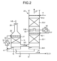
- FIG. 2 is a diagram simply illustrating another structure of the CO 2 recovery device according to this embodiment.
- the CO 2 absorber 23 may have two stages of countercurrent CO 2 -absorbing units 20-1 and 20-2 as illustrated in FIG. 2 , or may have three or more stages. If the CO 2 absorber 23 is provided with the countercurrent CO 2 -absorbing units 20-1 and 20-2, a semi-rich solution 24B, which has absorbed CO 2 remaining in the flue gas 14C after the lean solution 17 is sprayed from spray nozzles 43-2 and passes through the countercurrent CO 2 -absorbing unit 20-2, is stored in a receiving unit 55.
- the semi-rich solution 24B which is stored in the receiving unit 55, is cooled in a cooler 56 by cooling water 57, the semi-rich solution 24B is sprayed from spray nozzles 43-1 and passes through the countercurrent CO 2 -absorbing unit 20-1, so that the semi-rich solution 24B is changed into a semi-rich solution 24A.
- the semi-rich solution 24A is stored in the bottom of the CO 2 absorber 23.
- this embodiment is not limited to a case where the semi-rich solution 24B, which has absorbed CO 2 in the countercurrent CO 2 -absorbing unit 20-2, is supplied to the countercurrent CO 2 -absorbing unit 20-1 and the semi-rich solution 24A, which has absorbed CO 2 in the countercurrent CO 2 -absorbing unit 20-1, is supplied to the cocurrent flow CO 2 -absorbing unit 19.
- the rich solution 18 that has absorbed CO 2 in the cocurrent flow CO 2 -absorbing unit 19, and the semi-rich solutions 24A and 24B that have absorbed CO 2 in the countercurrent CO 2 -absorbing units 20-1 and 20-2, respectively, may be supplied to the cocurrent flow CO 2 -absorbing unit 19 and any one or both of the countercurrent CO 2 -absorbing units 20-1 and 20-2 again after being cooled.
- the regenerator 21 is a tower that includes the absorbent regenerating unit 13 and regenerates the rich solution 18 as the lean solution 17 by releasing CO 2 from the rich solution 18.
- the rich solution 18, which is released into the regenerator 21 from the top of the regenerator 21, is heated by steam 61 that is supplied from the bottom of the regenerator 21.
- the steam 61 is generated by the heat exchange between the lean solution 17 and saturated steam 62 in the regenerating superheater (reboiler) 36.
- the rich solution 18 absorbs heat by being heated by the steam 61, so that most of CO 2 contained in the rich solution 18 is released.
- the rich solution 18 is changed into the CO 2 absorbent (lean solution) 17 from which almost all CO 2 has been removed.
- the lean solution 17 which is stored in the bottom of the regenerator 21, is fed as a CO 2 absorbent by a lean solvent pump 63 and is cooled in a lean solvent cooler 64 by the heat exchange with cooling water 65, the lean solution 17 is fed to the CO 2 absorber 23.
- CO 2 gas 71 containing vapor is released from the top of the regenerator 21.
- vapor contained in the CO 2 gas 71 is condensed in a condenser 72 by cooling water 73, and water 75 is separated by a separation drum 74.
- CO 2 gas 76 is released to the outside of the system and is recovered.
- the water 75 which is separated by the separation drum 74, is supplied to the upper portion of the regenerator 21 by a condensed water circulating pump 77.
- the CO 2 recovery device 10 includes the cocurrent flow CO 2 absorber 22 that includes the cocurrent flow CO 2 -absorbing unit 19 and is provided between the cooling tower 16 and the CO 2 absorber 23, and uses the semi-rich solution 24, which has absorbed CO 2 contained in the flue gas 14C in the CO 2 absorber 23, as an absorbent that further absorbs CO 2 contained in the flue gas 14B in the cocurrent flow CO 2 absorber 22. Accordingly, it is possible to increase the concentration of CO 2 contained in the rich solution 18 that is stored in the bottom of the cocurrent flow CO 2 absorber 22.
- the semi-rich solution 24 is previously cooled before being supplied into the cocurrent flow CO 2 absorber 22, it is possible to lower the temperature of the flue gas 14C that is fed to the CO 2 absorber 23. For this reason, it is also possible to increase the absorption amount of CO 2 , which is contained in the flue gas 14C, in the CO 2 absorber 23 and to reduce the consumption of the absorbent.
- the CO 2 recovery device 10 is adapted so that the countercurrent CO 2 -absorbing unit 20 is provided in the CO 2 absorber 23.
- this embodiment is not limited thereto and the countercurrent CO 2 -absorbing unit 20 may be provided between the cooling unit 11 and the CO 2 absorber 23.
- the CO 2 recovery device 10 is not limited to a case where the CO 2 recovery device 10 is applied to recover CO 2 contained in the flue gas 14A, and may be suitably used as a device that brings an ingredient contained in flue gas into gas-liquid contact with liquid such as water, such as flue gas desulphurization equipment.
- a CO 2 recovery device according to a second embodiment of the invention will be described with reference to the drawings. Since the structure of the CO 2 recovery device according to this embodiment is the same as the structure of the above-mentioned CO 2 recovery device illustrated in FIG. 1 , a diagram illustrating the structure of the CO 2 recovery device will not be provided and description will be made using only drawings illustrating the structure of a cooling tower and a CO 2 absorber. Meanwhile, the same members as the members of the CO 2 recovery device illustrated in FIGS. 1 and 2 are denoted by the same reference numerals and the description thereof will not be made. Further, a case where two countercurrent CO 2 -absorbing units 20 are provided as illustrated in FIG. 2 will be described in this embodiment.
- FIG. 3 is a diagram simply illustrating a part of the structure of the CO 2 recovery device according to the second embodiment of the invention.
- the CO 2 recovery device according to this embodiment has a structure where the CO 2 recovery device according to the first embodiment illustrated in FIG. 2 further includes a countercurrent CO 2 -absorbing unit 81 provided on the most upstream side in the flow direction of the flue gas 14B.
- the CO 2 recovery device includes countercurrent CO 2 -absorbing units 20-1 and 20-2 that are provided in the CO 2 absorber 23, the cocurrent flow CO 2 absorber 22 that is provided between the cooling tower 16 and the CO 2 absorber 23, and the countercurrent CO 2 -absorbing unit 81 that is provided on the downstream side of the cooling unit 11, which is provided in the cooling tower 16, in the gas flow direction (in an upper portion of the tower).
- the cooling tower 16 includes spray nozzles 82 and the countercurrent CO 2 -absorbing unit 81 that are provided therein.
- the countercurrent CO 2 -absorbing unit 81 removes CO 2 from the flue gas 14B by bringing the cooled flue gas 14B into contact with a rich solution 18A, which is discharged from the cocurrent flow CO 2 absorber 22, in a countercurrent flow.
- the spray nozzles 82 spray the rich solution 18A downward. After the rich solution 18A is discharged from the cocurrent flow CO 2 absorber 22 through a rich solution extraction line 83 and is cooled in a cooler 84 by the heat exchange with cooling water 85, the rich solution 18A is fed to the cocurrent flow CO 2 absorber 22.
- the countercurrent CO 2 -absorbing unit 81 is provided on the downstream side of the cooling unit 11 in the gas flow direction.
- the countercurrent CO 2 -absorbing unit 81 is provided above the cooling unit 11 of the cooling tower 16. For this reason, the flue gas 14B, which is cooled in the cooling unit 11 of the cooling tower 16, flows to the countercurrent CO 2 -absorbing unit 81.
- the rich solution 18A is stored in a receiving unit 86.
- the flue gas 14B which is supplied to the countercurrent CO 2 -absorbing unit 81, comes into counterflow contact with the rich solution 18A in the countercurrent CO 2 -absorbing unit 81.
- the rich solution 18A absorbs CO 2 , which is contained in the flue gas 14B, by coming into counterflow contact with the flue gas 14B in the cocurrent flow CO 2 absorber 22. Accordingly, it is possible to remove CO 2 from the flue gas 14B.
- the rich solution 18A is stored in the receiving unit 86 after coming into contact with the cooled flue gas 14B in the countercurrent CO 2 -absorbing unit 81. However, a rich solution 18B, which is stored in the receiving unit 86, is extracted from a rich solution feed line 87, and is supplied to the regenerator 21.
- the CO 2 recovery device uses the semi-rich solution 24A, which is discharged from the CO 2 absorber 23, as an absorbent that absorbs CO 2 contained in flue gas 14C-1 in the cocurrent flow CO 2 absorber 22. Further, the CO 2 recovery device uses the rich solution 18A, which is discharged from the cocurrent flow CO 2 absorber 22, as an absorbent that further absorbs CO 2 contained in the flue gas 14B in the cooling tower 16. That is, the rich solution 18A is an absorbent that has absorbed CO 2 contained in the flue gas 14C-1 in the cocurrent flow CO 2 absorber 22 and has absorbed CO 2 contained in flue gas 14C-2 in the CO 2 absorber 23.
- a reflux ratio (A4/A3) of the rich solution 18B is preferably in a range of 0 to 3 and more preferably in a range of 0 to 2. Accordingly, it is possible to absorb CO 2 , which is contained in the flue gas 14B, while suitably maintaining the rich solution 18B that is fed to the regenerator 21 and regenerated.
- the rich solution 18A since the rich solution 18A is cooled before being supplied into the cooling tower 16, the rich solution 18A can lower the temperature of the flue gas 14C-1 fed to the CO 2 absorber 23 by coming into contact with the flue gas 14B. Furthermore, since the semi-rich solution 24A is also cooled before being supplied into the cocurrent flow CO 2 absorber 22, the semi-rich solution 24A also can lower the temperature of the flue gas 14C-2 that is fed to the CO 2 absorber 23. For this reason, it is possible to increase the absorption amount of CO 2 , which is contained in the flue gas 14C, in the CO 2 absorber 23. Accordingly, it is possible to improve the absorption efficiency of CO 2 and to reduce the consumption of the absorbent.
- the CO 2 recovery device according to this embodiment is provided with the cocurrent flow CO 2 absorber 22 on the flue gas duct 29 of the CO 2 recovery device having been already provided and is provided with the countercurrent CO 2 -absorbing unit 81 on the downstream side in the cooling tower 16 in the gas flow direction (in an upper portion of the tower), it is possible to effectively use an installation area.
- the CO 2 recovery device of this embodiment since it is possible to improve the absorption efficiency of CO 2 , which is contained in the flue gas 14A, into a CO 2 absorbent 17 and to reduce the consumption of the absorbent contained in the CO 2 absorbent 17, it is possible to efficiently use the CO 2 absorbent 17. Accordingly, since it is possible to efficiently use steam required for releasing CO 2 , which is contained in the CO 2 absorbent 17, in the regenerator 21 without the waste of steam, it is possible to further increase the operating efficiency of the CO 2 recovery device. Further, it is also possible to more effectively apply this embodiment to the device that has been already provided.
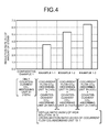
- FIG. 4 is a diagram illustrating a relation between the filling height of the cocurrent flow CO 2 -absorbing unit 19 of the cocurrent flow CO 2 absorber 22 and the reduction rate of the amount of steam that is consumed by the reboiler 36.
- Comparative Example 1 is a test example where the filling height of the countercurrent CO 2 -absorbing unit 20 of the CO 2 absorber 23 is 100% in a CO 2 recovery device in the related art without the cocurrent flow CO 2 absorber 22.
- the amount of steam consumed by the reboiler 36 was a reference value (0%).
- Example 1-1 is a test example where the filling height of the cocurrent flow CO 2 -absorbing unit 19 of the cocurrent flow CO 2 absorber 22 is 14% when the filling height of the countercurrent CO 2 -absorbing unit 20 of the CO 2 absorber 23 is 100%.
- Example 1-2 is a test example where the height of the cocurrent flow CO 2 -absorbing unit 19 of the cocurrent flow CO 2 absorber 22 is 28% when the height of the countercurrent CO 2 -absorbing unit 20 of the CO 2 absorber 23 is 100%.
- Example 1-3 is a test example where the height of the cocurrent flow CO 2 -absorbing unit 19 of the cocurrent flow CO 2 absorber is 43% when the height of the countercurrent CO 2 -absorbing unit 20 of the CO 2 absorber 23 is 100%.
- the reduction rate of the amount of steam consumed by the reboiler 36 was increased as the filling height of the cocurrent flow CO 2 -absorbing unit 19 of the cocurrent flow CO 2 absorber 22 was increased. Accordingly, when the cocurrent flow CO 2 absorber 22 is provided on the flue gas duct 29, it is possible to increase the reduction rate of the amount of steam consumed by the reboiler 36 as the filling height of the cocurrent flow CO 2 -absorbing unit 19 of the cocurrent flow CO 2 absorber 22 is increased.
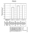
- FIG. 5 is a diagram illustrating a relation between the reflux ratio (A2/A1) of the semi-rich solution 24 where the semi-rich solution 24 is circulated again in the cocurrent flow CO 2 absorber 22 and the reduction rate of the amount of steam that is consumed by the reboiler 36.
- Comparative Example 2 is a test example where the filling height of the countercurrent CO 2 -absorbing unit 20 of the CO 2 absorber 23 is 100% in the CO 2 recovery device in the related art without the cocurrent flow CO 2 absorber 22 as in Comparative Example 1.
- the amount of steam consumed by the reboiler 36 was a reference value (0%).
- Example 2-1 to 2-3 is a test example where the height of the cocurrent flow CO 2 -absorbing unit 19 of the cocurrent flow CO 2 absorber 22, when the height of the countercurrent CO 2 -absorbing unit 20 of the CO 2 absorber 23 is 100%, is 28% so that the cross-section ratio (S1/S2) is 1.
- Example 2-1 the reflux ratio of the semi-rich solution 24 was 0.
- Example 2-2 the reflux ratio of the semi-rich solution 24 was 1.
- Example 2-3 the reflux ratio of the semi-rich solution 24 was 2.
- the reduction rate of the amount of steam consumed by the reboiler 36 was increased as the reflux ratio (A2/A1) of the rich solution 18 circulated in the cocurrent flow CO 2 absorber 22 was increased. Accordingly, when the cocurrent flow CO 2 absorber 22 is provided on the flue gas duct 29, it is possible to increase the reduction rate of the amount of steam consumed by the reboiler 36 as the reflux ratio of the rich solution 18 circulated in the cocurrent flow CO 2 absorber 22 is increased.
- FIG. 6 is a diagram illustrating a relation between the cross-section ratio of the cocurrent flow CO 2 absorber 22 and the reduction rate of the amount of steam that is consumed by the reboiler 36.
- Comparative Example 3 is a test example where the filling height of the countercurrent CO 2 -absorbing unit 20 of the CO 2 absorber 23 is 100% in the CO 2 recovery device in the related art without the cocurrent flow CO 2 absorber 22 as in Comparative Examples 1 and 2.
- Example 3-1 is a test example where the height of the cocurrent flow CO 2 -absorbing unit 19 of the cocurrent flow CO 2 absorber 22, when the filling height of the countercurrent CO 2 -absorbing unit 20 of the CO 2 absorber 23 is 100%, is 28% so that the reflux ratio (A2/A1) of the rich solution 18 is 0.
- the cross-section ratio (S1/S2) of the cocurrent flow CO 2 -absorbing unit 19 was 1.
- the cross-section ratio (S1/S2) of the cocurrent flow CO 2 -absorbing unit 19 was 0.75.
- the cross-section ratio (S1/S2) of the cocurrent flow CO 2 -absorbing unit 19 was 0.5.
- the cocurrent flow CO 2 absorber 22 is provided on the flue gas duct 29, it is possible to increase the reduction rate of the amount of steam, which is consumed by the reboiler 36, by making the cross-section ratio (S1/S2) of the cocurrent flow CO 2 -absorbing unit 19 larger than 0.5.
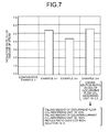
- FIG. 7 is a diagram illustrating a relation between a case where the cross-section ratio (S1/S2) of the cocurrent flow CO 2 -absorbing unit 19 and the filling height of the cocurrent flow CO 2 -absorbing unit 19 are changed, and the reduction rate of the amount of steam that is consumed by the reboiler 36.
- Example 3-4 is a test example where the height of the cocurrent flow CO 2 -absorbing unit 19 of the cocurrent flow CO 2 absorber 22 is 43%, the reflux ratio (A2/A1) of the rich solution 18 is 0, and the cross-section ratio (S1/S2) of the cocurrent flow CO 2 -absorbing unit 19 is 0.5 when the height of the countercurrent CO 2 -absorbing unit 20 of the CO 2 absorber 23 is 100%.
- the cocurrent flow CO 2 absorber 22 is provided on the flue gas duct 29 and the cross-section ratio (S1/S2) of the cocurrent flow CO 2 -absorbing unit 19 is small, it is possible to increase the reduction rate of the amount of steam, which is consumed by the reboiler 36, by making the filling height of the cocurrent flow CO 2 -absorbing unit 19 high.
- FIG. 8 is a diagram illustrating a relation between the filling height of the cocurrent flow CO 2 -absorbing unit 19 of the cocurrent flow CO 2 absorber 22 and the reduction rate of the amount of steam that is consumed by the reboiler 36.
- Comparative Example 4-1 is a test example where the filling height of the countercurrent CO 2 -absorbing unit 20 of the CO 2 absorber 23 is 100% in the CO 2 recovery device in the related art without the cocurrent flow CO 2 absorber 22 as in Comparative Example 1.
- the amount of steam consumed by the reboiler 36 was a reference value (0%).
- Comparative Example 4-2 is a test example where the countercurrent CO 2 -absorbing unit 20 of the CO 2 absorber 23 is formed in two stages and the sum of the filling heights of the countercurrent CO 2 -absorbing units 20-1 and 20-2 is 100% in the CO 2 recovery device in the related art without the cocurrent flow CO 2 absorber 22.
- Example 4-1 is a test example where the filling height of the cocurrent flow CO 2 -absorbing unit 19 is 14% when the sum of the filling heights of the countercurrent CO 2 -absorbing units 20-1 and 20-2 of the CO 2 absorber 23 is 100%.
- Example 4-2 is a test example where the filling height of the cocurrent flow CO 2 -absorbing unit 19 is 28% when the sum of the filling heights of the countercurrent CO 2 -absorbing units 20-1 and 20-2 of the CO 2 absorber 23 is 100%.
- Example 4-3 is a test example where the filling height of the cocurrent flow CO 2 -absorbing unit 19 is 43% when the sum of the filling heights of the countercurrent CO 2 -absorbing units 20-1 and 20-2 of the CO 2 absorber 23 is 100%.
- the filling height of the countercurrent CO 2 -absorbing unit 20-1 was 29% and the filling height of the countercurrent CO 2 -absorbing unit 20-2 was 71%.
- the reflux ratio (A2/A1) of the rich solution 18 was 0 and the cross-section ratio (S1/S2) of the cocurrent flow CO 2 -absorbing unit 19 was 1.
- Example 4-1 when the countercurrent CO 2 -absorbing unit 20 of the CO 2 absorber 23 was formed in two stages and the cocurrent flow CO 2 absorber 22 was provided on the flue gas duct 29 as in Example 4-1, the reduction rate of the amount of steam consumed by the reboiler 36 was further increased. Further, as in Examples 4-1 to 4-3, the reduction rate of the amount of steam consumed by the reboiler 36 was increased as the filling height of the cocurrent flow CO 2 -absorbing unit 19 of the cocurrent flow CO 2 absorber 22 was increased.
- the countercurrent CO 2 -absorbing unit 20 of the CO 2 absorber 23 is formed in a plurality of stages and the cocurrent flow CO 2 absorber 22 is provided on the flue gas duct 29, it is possible to further increase the reduction rate of the amount of steam that is consumed by the reboiler 36. Furthermore, it is possible to increase the reduction rate of the amount of steam, which is consumed by the reboiler 36, as the height of the cocurrent flow CO 2 -absorbing unit 19 of the cocurrent flow CO 2 absorber 22 is increased.
- FIG. 9 is a diagram illustrating a relation between the filling height of the countercurrent CO 2 -absorbing unit 81 and the reduction rate of the amount of steam that is consumed by the reboiler 36.
- Comparative Example 5-1 is a test example where the filling height of the countercurrent CO 2 -absorbing unit 20 of the CO 2 absorber 23 is 100% in the CO 2 recovery device in the related art without the cocurrent flow CO 2 absorber 22 as in Comparative Example 4-1.
- the amount of steam consumed by the reboiler 36 was a reference value (0%).
- Comparative Example 5-2 is a test example where the countercurrent CO 2 -absorbing unit 20 of the CO 2 absorber 23 is formed in two stages and the sum of the filling heights of the countercurrent CO 2 -absorbing units 20-1 and 20-2 is 100% in the CO 2 recovery device in the related art without the cocurrent flow CO 2 absorber 22 as in Comparative Example 4-2.
- Comparative Example 5-3 is a test example where the sum of the filling heights of the cocurrent flow CO 2 -absorbing unit 19 is 14%, the countercurrent CO 2 -absorbing unit 20 of the CO 2 absorber 23 is formed in two stages, and the sum of the filling heights of the countercurrent CO 2 -absorbing units 20-1 and 20-2 is 100% in the CO 2 recovery device including the cocurrent flow CO 2 absorber 22.
- Example 5-1 is a test example where the filling height of the countercurrent CO 2 -absorbing unit 81 is 14% when the sum of the filling heights of the countercurrent CO 2 -absorbing units 20-1 and 20-2 of the CO 2 absorber 23 is 100%.
- Example 5-2 is a test example where the filling height of the countercurrent CO 2 -absorbing unit 81 is 28% when the sum of the filling heights of the countercurrent CO 2 -absorbing units 20-1 and 20-2 of the CO 2 absorber 23 is 100%.
- Example 5-3 is a test example where the filling height of the countercurrent CO 2 -absorbing unit 81 is 43% when the sum of the filling heights of the countercurrent CO 2 -absorbing units 20-1 and 20-2 of the CO 2 absorber 23 is 100%.
- the filling height of the countercurrent CO 2 -absorbing unit 20-1 was 29% and the filling height of the countercurrent CO 2 -absorbing unit 20-2 was 71%. Furthermore, in all of Examples 5-1 to 5-3 and Comparative Example 5-3, the filling height of the cocurrent flow CO 2 -absorbing unit 19 of the cocurrent flow CO 2 absorber 22 was 28%. Moreover, in all of Examples 5-1 to 5-3 and Comparative Example 5-3, the reflux ratio (A2/A1) of the rich solution 18A was 0 and the cross-section ratio (S1/S2) of the cocurrent flow CO 2 -absorbing unit 19 was 1.
- the reduction rate of the amount of steam consumed by the reboiler 36 was increased when the countercurrent CO 2 -absorbing unit 81 was provided in the cooling tower 16 and the cocurrent flow CO 2 absorber 22 was provided between the cooling tower 16 and the CO 2 absorber 23 (see Examples 5-1 to 5-3). Moreover, the reduction rate of the amount of steam consumed by the reboiler 36 was increased as the filling height of the countercurrent CO 2 -absorbing unit 81 provided in the cooling tower 16 was increased.
Landscapes
- Chemical & Material Sciences (AREA)
- Engineering & Computer Science (AREA)
- Analytical Chemistry (AREA)
- General Chemical & Material Sciences (AREA)
- Oil, Petroleum & Natural Gas (AREA)
- Chemical Kinetics & Catalysis (AREA)
- Gas Separation By Absorption (AREA)
- Treating Waste Gases (AREA)
- Carbon And Carbon Compounds (AREA)
Abstract
Description
- The present invention relates to a CO2 recovery device that absorbs CO2 contained in flue gas.
- Flue gas, which is generated through the combustion of fossil fuel in a boiler of a thermoelectric power plant or the like using a large amount of fossil fuel, contains CO2. A method of removing and recovering CO2, which is contained in flue gas, by bringing flue gas, which contains CO2, into gas-liquid contact with an amine-based CO2 absorbent in a CO2 absorber so that CO2 is absorbed in the CO2 absorbent, and a method of storing the recovered CO2 without releasing the recovered CO2 into the atmosphere have been energetically studied.
- For example, there is used a method of making the CO2 absorbent absorb CO2, which is contained in the flue gas, in the CO2 absorber to remove CO2 from the flue gas, regenerating the CO2 absorbent by releasing CO2, which is absorbed in the CO2 absorbent, in a regenerator, and reusing the CO2 absorbent to remove CO2 from flue gas by circulating the CO2 absorbent in the CO2 absorber again (for example, see Patent Literature 1). In this case, the CO2 absorbent absorbing CO2 releases CO2 by being heated with steam in the regenerator. As a result, highly-pure CO2 is recovered.
- Patent Literature 1: Japanese Laid-open Patent Publication NO.
2008-62165 - Since a CO2 recovery device, which uses a method of absorbing, removing, and recovering CO2 from gas, which contains CO2, such as flue gas, by using a CO2 absorbent, is additionally installed on a combustion facility, the operating cost of the CO2 recovery device should be reduced as much as possible. In particular, much thermal energy is consumed for the release of CO2 in a regenerator of the CO2 recovery device. Further, if the consumption of the CO2 absorbent is large, the amount of a CO2 absorbent to be additionally supplied is increased. Accordingly, the increase of operating cost is caused.
- For this reason, there is demanded a CO2 recovery device that improves CO2 recovery efficiency, reduces the consumption of the CO2 absorbent, and reduces operating cost when recovering CO2 from the flue gas.
- The invention has been made in consideration of the above-mentioned circumstances, and an object of the invention is to provide a CO2 recovery device that efficiently recovers CO2, reduces the consumption of a CO2 absorbent, and reduces operating cost.
- According to a first aspect of the present invention in order to solve the above mentioned problems, there is provided a CO2 recovery device including:
- a cooling unit for bringing the flue gas, which contains CO2, into contact with water so as to cool flue gas;
- a CO2-absorbing unit for bringing the flue gas into contact with a CO2 absorbent absorbing CO2 so as to remove CO2 from the flue gas; and
- an absorbent regenerating unit for releasing CO2 from the CO2 absorbent having absorbed CO2 so as to regenerate the CO2 absorbent, wherein
- the CO2-absorbing unit includes:
- at least one countercurrent CO2-absorbing unit for bringing the flue gas into contact with the CO2 absorbent in a countercurrent flow so as to remove CO2 from the flue gas; and
- at least one cocurrent flow CO2-absorbing unit for bringing the flue gas into contact with the CO2 absorbent in a cocurrent flow so as to remove CO2 from the flue gas.
- According to a second aspect of the present invention, there is provided the CO2 recovery device according to the first aspect, wherein the CO2 absorbent having absorbed CO2 is cooled in the CO2-absorbing unit, and is supplied to the CO2-absorbing unit again.
- According to a third aspect of the present invention, there is provided the CO2 recovery device according to the first or second aspect, wherein the cocurrent flow CO2-absorbing unit is provided on the most upstream side in a flow direction of the flue gas.
- According to a fourth aspect of the present invention, there is provided the CO2 recovery device according to any one of the first to third aspects, wherein the countercurrent CO2-absorbing unit is provided on the most upstream side in the flow direction of the flue gas.
- According to a fifth aspect of the present invention, there is provided the CO2 recovery device according to any one of the first to fourth aspects, wherein at least one of the countercurrent CO2-absorbing unit and the cocurrent flow CO2-absorbing unit, which are included in the CO2-absorbing unit, is provided in a CO2 absorber for bringing the flue gas into contact with the CO2 absorbent so as to remove CO2 from the flue gas, and the cocurrent flow CO2-absorbing unit is provided between the cooling unit and the CO2 absorber.
- According to a sixth aspect of the present invention, there is provided the CO2 recovery device according to any one of the first to fifth aspects, wherein at least one of the countercurrent CO2-absorbing unit and the cocurrent flow CO2-absorbing unit, which are included in the CO2-absorbing unit, is provided in the CO2 absorber for bringing the flue gas into contact with the CO2 absorbent so as to remove CO2 from the flue gas, and the countercurrent CO2-absorbing unit is provided between the cooling unit and the CO2 absorber.
- According to a seventh aspect of the present invention, there is provided the CO2 recovery device according to any one of the first to sixth aspects, wherein the cooling unit is provided in a cooling tower for bringing the flue gas into contact with water so as to cool the flue gas, and the countercurrent CO2 absorber is provided in the cooling tower.
- According to the CO2 recovery device of the invention, it is possible to efficiently recover CO2, to reduce the consumption of a CO2 absorbent, and to reduce operating cost.
-
-
FIG. 1 is a diagram simply illustrating the structure of a CO2 recovery device according to a first embodiment of the invention. -
FIG. 2 is a diagram simply illustrating another structure of the CO2 recovery device according to the first embodiment of the invention. -
FIG. 3 is a diagram simply illustrating a part of the structure of a CO2 recovery device according to a second embodiment of the invention. -
FIG. 4 is a diagram illustrating a relation between the filling height of a cocurrent flow CO2-absorbing unit of a cocurrent flow CO2 absorber and the reduction rate of the amount of steam that is consumed by a reboiler. -
FIG. 5 is a diagram illustrating a relation between a reflux ratio of a semi-rich solution where a semi-rich solution is circulated again in the cocurrent flow CO2 absorber and the reduction rate of the amount of steam that is consumed by the reboiler. -
FIG. 6 is a diagram illustrating a relation between a cross-section ratio of the cocurrent flow CO2 absorber and the reduction rate of the amount of steam that is consumed by the reboiler. -
FIG. 7 is a diagram illustrating a relation between a case where a cross-section ratio (S1/S2) of the cocurrent flow CO2-absorbing unit and the filling height of the cocurrent flow CO2-absorbing unit are changed, and the reduction rate of the amount of steam that is consumed by the reboiler. -
FIG. 8 is a diagram illustrating a relation between the filling height of the cocurrent flow CO2-absorbing unit of the cocurrent flow CO2 absorber and the reduction rate of the amount of steam that is consumed by the reboiler. -
FIG. 9 is a diagram illustrating a relation between the filling height of a countercurrent CO2-absorbing unit and the reduction rate of the amount of steam that is consumed by the reboiler. - The invention will be described in detail below with reference to the drawings. Meanwhile, the invention is not limited by the following forms that embody the invention (hereinafter, referred to as embodiments). Further, components of the following embodiments include components that can be easily supposed by those skilled in the art and substantially the same components, that is, components corresponding to a so-called equivalent range. Furthermore, components disclosed in the following embodiments may be appropriately combined with each other.
- A CO2 recovery device according to a first embodiment of the invention will be described with reference to the drawings.
FIG. 1 is a diagram simply illustrating the structure of a CO2 recovery device according to the first embodiment of the invention. As illustrated inFIG. 1 , the CO2 recovery device 10 according to this embodiment includes acooling unit 11, a CO2-absorbing unit 12, and anabsorbent regenerating unit 13. Thecooling unit 11cools flue gas 14A by bringing theflue gas 14A containing CO2 into contact withwater 15, and is provided in acooling tower 16. Further, the CO2-absorbing unit 12 removes CO2 fromflue gas 14B by bringing theflue gas 14B into contact with a CO2 absorbent (lean solution) 17 which absorbs CO2. In this embodiment, the CO2-absorbing unit 12 includes a cocurrent flow CO2-absorbing unit 19 that removes CO2 from theflue gas 14B by bringing theflue gas 14B into contact with a CO2 absorbent (semi-rich solution) 24, which has absorbed CO2, in a cocurrent flow, and a countercurrent CO2-absorbing unit 20 that removes CO2 fromflue gas 14C by bringing theflue gas 14C into contact with the CO2 absorbent 17 in a countercurrent flow. Furthermore, theabsorbent regenerating unit 13 regenerates the CO2 absorbent 17 by releasing CO2 from arich solution 18, and is provided in an absorbent regenerator (hereinafter, referred to as a regenerator) 21. - In this embodiment, the cocurrent flow CO2-absorbing unit 19 is provided in a cocurrent flow CO2 absorber 22 and the countercurrent CO2-absorbing unit 20 is provided in a CO2 absorber 23.
- In this embodiment, the CO2-absorbing
unit 12 includes one cocurrent flow CO2-absorbing unit 19 and one countercurrent CO2-absorbing unit 20. However, the CO2-absorbing unit 12 may include a plurality of cocurrent flow CO2-absorbing units 19 and one countercurrent CO2-absorbing unit 20, may include one cocurrent flow CO2-absorbing unit 19 and a plurality of countercurrent CO2-absorbing units 20, or may include a plurality of cocurrent flow CO2-absorbing units 19 and a plurality of countercurrent CO2-absorbing units 20. - In the CO2 recovery device 10, the CO2 absorbent 17, which absorbs CO2 contained in the
flue gas 14A, circulates among the cocurrent flow CO2 absorber 22, the CO2 absorber 23, and the regenerator 21 (hereinafter, referred to as "in a system"). In this embodiment, therich solution 18, which has absorbed CO2 contained in theflue gas 14B, is fed to theregenerator 21 from the cocurrent flow CO2 absorber 22. The CO2 absorbent (lean solution) 17, which is regenerated by removing almost all of CO2 from therich solution 18 in theregenerator 21, is fed to the CO2 absorber 23 from theregenerator 21. The CO2 absorbent (semi-rich solution) 24, which has absorbed CO2 remaining in theflue gas 14C, is fed to the cocurrent flow CO2 absorber 22 from the CO2 absorber 23. - The
flue gas 14A is gas that contains CO2 discharged from industrial equipment, such as a boiler or a gas turbine. After the pressure of theflue gas 14A is increased by a flue gas blower or the like, theflue gas 14A is sent to thecooling tower 16. - The
cooling tower 16 is a tower that cools theflue gas 14A bywater 15. Thecooling tower 16 includesspray nozzles 26 that spray thewater 15 into the tower, and acooling unit 11. Theflue gas 14A is cooled by coming into counterflow contact with thewater 15 sprayed from thespray nozzles 26 in thecooling unit 11 of thecooling tower 16. - The
water 15 of which the temperature has become high by the heat exchange between thewater 15 and theflue gas 14A is stored in the bottom of thecooling tower 16. Thewater 15 stored in the bottom of thecooling tower 16 is extracted from the bottom of thecooling tower 16, and is cooled by exchanging heat with coolingwater 28 in a cooler 27. Then, thewater 15 is fed to thecooling tower 16. Accordingly, thewater 15 is circulated and used to cool theflue gas 14A. - The cooled
flue gas 14B is discharged from thecooling tower 16 through aflue gas duct 29 that connects thecooling tower 16 to the CO2 absorber 23, and is fed to the CO2-absorbing unit 12. - As described above, the CO2-absorbing unit 12 includes the cocurrent flow CO2-absorbing unit 19 and the countercurrent CO2-absorbing unit 20. The
flue gas 14B is fed to the cocurrent flow CO2 absorber 22 including the cocurrent flow CO2-absorbing unit 19 and the CO2 absorber 23 including the countercurrent CO2-absorbing unit 20 in this order. - The cocurrent flow CO2 absorber 22 is provided between the cooling
tower 16 including thecooling unit 11 and the CO2 absorber 23. In this embodiment, the cocurrent flow CO2 absorber 22 including the cocurrent flow CO2-absorbing unit 19 is provided on the most upstream side in the flow direction of theflue gas 14B flowing in the CO2-absorbing unit 12. Theflue gas 14B discharged from thecooling tower 16 is fed to the cocurrent flow CO2 absorber 22 through theflue gas duct 29. - The cocurrent flow CO2 absorber 22 is a tower that removes CO2 from the
flue gas 14B by bringing theflue gas 14B into contact with thesemi-rich solution 24, which is discharged from the CO2 absorber 23, in a cocurrent flow. The cocurrent flow CO2 absorber 22 includesspray nozzles 31 and the cocurrent flow CO2-absorbing unit 19 that are provided in the tower. The spray nozzles 31 spray thesemi-rich solution 24 downward. After thesemi-rich solution 24 is discharged from the CO2 absorber 23 through a semi-richsolution extraction line 32 and is cooled by exchanging heat with coolingwater 34 in a cooler 33, thesemi-rich solution 24 is fed to the cocurrent flow CO2 absorber 22. Further, theflue gas 14B is supplied from the top of the cocurrent flow CO2 absorber 22, and flows in the tower toward the bottom of the tower. - Accordingly, since the
semi-rich solution 24 is cooled before being supplied into the cocurrent flow CO2 absorber 22, thesemi-rich solution 24 can further absorb CO2, which is contained in theflue gas 14B, in the cocurrent flow CO2 absorber 22. Therefore, it is possible to increase the concentration of CO2 contained in therich solution 18 that is stored in the bottom of the cocurrent flow CO2 absorber 22. - Further, since the
semi-rich solution 24 is cooled before being supplied into the cocurrent flow CO2 absorber 22, thesemi-rich solution 24 can lower the temperature of theflue gas 14C fed to the CO2 absorber 23 by coming into contact with theflue gas 14B. For this reason, as described below, it is possible to increase the absorption amount of CO2, which is contained in theflue gas 14C, even in the CO2 absorber 23. Accordingly, it is possible to improve the absorption efficiency of CO2. Furthermore, since the temperature of theflue gas 14C fed to the CO2 absorber 23 is lowered, the steam pressure of the absorbent of thelean solution 17 is reduced. Accordingly, it is possible to reduce the consumption of the absorbent. Moreover, the temperature of the absorbent rises due to the heat of reaction that is generated at the time of absorption of CO2, but theflue gas 14C is cooled on the upstream side of the CO2 absorber 23. Accordingly, the rise of the temperature of the absorbent is also suppressed, so that it is possible to suppress the degradation of the absorbent. - Further, in a CO2 recovery device in the related art, a
cooling tower 16 and a CO2 absorber 23 have been connected to each other by aflue gas duct 29. In contrast, the CO2 recovery device 10 according to this embodiment is provided with the cocurrent flow CO2 absorber 22 on theflue gas duct 29. Accordingly, according to the CO2 recovery device 10 of this embodiment, it is possible to effectively use an installation area since the cocurrent flow CO2 absorber 22 is provided on theflue gas duct 29 of the CO2 recovery device that has been already provided in the related art. - When the cross-sectional area of the cocurrent flow CO2-absorbing unit 19 is denoted by S1 and the cross-sectional area of the countercurrent CO2-absorbing unit 20 is denoted by S2, the cross-section ratio (S1/S2) of the cocurrent flow CO2-absorbing unit 19 is preferably 1.0 or less, more preferably 0.8 or less, and still more preferably 0.5 or less. Accordingly, since it is possible to suitably maintain a contact rate between the
semi-rich solution 24 and theflue gas 14B in the cocurrent flow CO2 absorber 22, it is possible to maintain the absorption efficiency of CO2 that is contained in theflue gas 14B. As a result, it is possible to reduce the amount of steam that is consumed by a regenerating superheater (reboiler) 36 of theregenerator 21. Moreover, even though the cross-section ratio (S1/S2) of the cocurrent flow CO2-absorbing unit 19 is small, it is possible to suitably maintain the contact rate between thesemi-rich solution 24 and theflue gas 14B in the cocurrent flow CO2 absorber 22 by increasing the filling height of the cocurrent flow CO2-absorbing unit 19 as much as that. Therefore, it is possible to maintain the absorption efficiency of CO2 that is contained in theflue gas 14B. - Further, the
semi-rich solution 24 is previously cooled in the cooler 33 before being supplied to the cocurrent flow CO2 absorber 22. However, when thesemi-rich solution 24 does not need to be cooled, thesemi-rich solution 24 may not be cooled in the cooler 33. - The
flue gas 14C, which comes into gas-liquid contact with thesemi-rich solution 24 in the cocurrent flow CO2 absorber 22, is sent to the CO2 absorber 23 from the side wall of the bottom of the CO2 absorber 23. - Furthermore, the
rich solution 18, which has absorbed CO2 contained in theflue gas 14B in the cocurrent flow CO2-absorbing unit 19, is stored in the bottom of the cocurrent flow CO2 absorber 22. Therich solution 18 stored in the bottom of the cocurrent flow CO2 absorber 22 is extracted from a richsolution feed line 37; is pumped from the bottom of the cocurrent flow CO2 absorber 22 by a richsolvent pump 38 that is provided outside; exchanges heat with the CO2 absorbent 17, which is regenerated in theregenerator 21, in a rich/leansolution heat exchanger 39; and is then supplied into the regenerator 21 from the side surface of the regenerator. - A part of the
rich solution 18, which is stored in the bottom of the cocurrent flow CO2 absorber 22, may be extracted from a rich solution extraction-branch line 41, may be mixed to thesemi-rich solution 24, and may circulate in the cocurrent flow CO2 absorber 22 so as to be used. Accordingly, since therich solution 18 can remove CO2 from theflue gas 14B by further absorbing CO2, which is contained in theflue gas 14B, in the cocurrent flow CO2 absorber 22, it is possible to further increase the concentration of CO2 contained in therich solution 18. As a result, it is possible to reduce the amount of steam that is consumed by thereboiler 36. - Further, when the flow rate of the
semi-rich solution 24, which is supplied to the cocurrent flow CO2 absorber 22 from the CO2 absorber 23, is denoted by A1 and the flow rate of therich solution 18, where therich solution 18 stored in the cocurrent flow CO2 absorber 22 is supplied to the cocurrent flow CO2 absorber 22 through the rich solution extraction-branch line 41, is denoted by A2, a reflux ratio (A2/A1) of therich solution 18 is preferably in a range of 0 to 3 and more preferably in a range of 0 to 2. Accordingly, it is possible to efficiently absorb CO2, which is contained in theflue gas 14B, while suitably maintaining therich solution 18 that is fed to theregenerator 21 and regenerated. - The CO2 absorber 23 is a tower that removes CO2 from the
flue gas 14C by bringing theflue gas 14C into contact with the CO2 absorbent 17. The CO2 absorber 23 includes the countercurrent CO2-absorbing unit 20,spray nozzles 43, awater washing unit 44, and ademister 45. Theflue gas 14C, which is fed into the CO2 absorber 23, flows in the tower toward the top of the tower from the bottom of the tower. Thespray nozzle 43 is a nozzle that sprays the CO2 absorbent 17 downward. In this embodiment, the countercurrent CO2-absorbing unit 20 is provided at the lower portion of the CO2 absorber 23. - The
flue gas 14C, which rises in the tower, comes into contact with the CO2 absorbent 17, which contains, for example, a basic amine compound as a base, in a countercurrent flow in the countercurrent CO2-absorbing unit 20. Accordingly, CO2 contained in theflue gas 14C is absorbed in the CO2 absorbent 17. - The
semi-rich solution 24, which has absorbed CO2 contained in theflue gas 14C in the countercurrent CO2-absorbing unit 20, is stored in the bottom of the CO2 absorber 23. As described above, thesemi-rich solution 24, which is stored in the bottom of the CO2 absorber 23, is extracted from the semi-richsolution extraction line 32, is fed to the cocurrent flow CO2 absorber 22, and absorbs CO2, which is contained in theflue gas 14B, by coming into contact with theflue gas 14B in a cocurrent flow. - This embodiment is not limited to a case where the
semi-rich solution 24 is fed to the cocurrent flow CO2 absorber 22, and thesemi-rich solution 24 may be mixed to the CO2 absorbent 17, which is fed to thespray nozzles 43, so as to be used to absorb CO2, which is contained in theflue gas 14C, in the countercurrent CO2-absorbing unit 20. Further, thesemi-rich solution 24 may be supplied to both the cocurrent flow CO2 absorber 22 and the countercurrent CO2-absorbing unit 20. - Furthermore, the
water washing unit 44 and thedemister 45 are provided on the downstream side in the CO2 absorber 23 in the flow direction of theflue gas 14C. In this embodiment, thewater washing unit 44 and thedemister 45 are provided above the countercurrent CO2-absorbing unit 20 in the tower. After the CO2 absorbent 17 contained in CO2-removed flue gas 47, from which CO2 has been removed in the countercurrent CO2-absorbing unit 20, is removed from the CO2-removed flue gas 47 in thewater washing unit 44 and thedemister 45, the CO2-removed flue gas 47 is released to the outside of the system from the top of the CO2 absorber 23. -
Water 48, which is supplied from the outside, is sprayed in thewater washing unit 44 fromspray nozzles 49, so that impurities contained in the CO2-removed flue gas 47 are removed in thewater washing unit 44. After thewater 48, which is sprayed from thespray nozzles 49, is recovered by a receivingunit 50, is fed to the outside of the tower by apump 51, and is cooled in a cooler 52 by coolingwater 53, thewater 48 is fed to thespray nozzles 49 so as to be used while circulating. - In this embodiment, the CO2-absorbing unit 12 includes one cocurrent flow CO2-absorbing unit 19 and one countercurrent CO2-absorbing unit 20. However, this embodiment is not limited thereto, and the CO2-absorbing unit 12 may include a plurality of cocurrent flow CO2-absorbing units 19 and one countercurrent CO2-absorbing unit 20, may include one cocurrent flow CO2-absorbing unit 19 and a plurality of countercurrent CO2-absorbing units 20, or may include a plurality of cocurrent flow CO2-absorbing units 19 and a plurality of countercurrent CO2-absorbing units 20.
- In this embodiment, the CO2 absorber 23 includes one countercurrent CO2-absorbing unit 20 that is provided therein. However, the CO2 absorber 23 may include a plurality of cocurrent flow CO2-absorbing units 19 and one countercurrent CO2-absorbing unit 20 that are provided therein, may include one cocurrent flow CO2-absorbing unit 19 and a plurality of countercurrent CO2-absorbing units 20 that are provided therein, or may include a plurality of cocurrent flow CO2-absorbing units 19 and a plurality of countercurrent CO2-absorbing units 20 that are provided therein.
-
FIG. 2 is a diagram simply illustrating another structure of the CO2 recovery device according to this embodiment. The CO2 absorber 23 may have two stages of countercurrent CO2-absorbing units 20-1 and 20-2 as illustrated inFIG. 2 , or may have three or more stages. If the CO2 absorber 23 is provided with the countercurrent CO2-absorbing units 20-1 and 20-2, asemi-rich solution 24B, which has absorbed CO2 remaining in theflue gas 14C after thelean solution 17 is sprayed from spray nozzles 43-2 and passes through the countercurrent CO2-absorbing unit 20-2, is stored in a receivingunit 55. Subsequently, after thesemi-rich solution 24B, which is stored in the receivingunit 55, is cooled in a cooler 56 by coolingwater 57, thesemi-rich solution 24B is sprayed from spray nozzles 43-1 and passes through the countercurrent CO2-absorbing unit 20-1, so that thesemi-rich solution 24B is changed into asemi-rich solution 24A. Thesemi-rich solution 24A is stored in the bottom of the CO2 absorber 23. - In this case, this embodiment is not limited to a case where the
semi-rich solution 24B, which has absorbed CO2 in the countercurrent CO2-absorbing unit 20-2, is supplied to the countercurrent CO2-absorbing unit 20-1 and thesemi-rich solution 24A, which has absorbed CO2 in the countercurrent CO2-absorbing unit 20-1, is supplied to the cocurrent flow CO2-absorbing unit 19. Therich solution 18 that has absorbed CO2 in the cocurrent flow CO2-absorbing unit 19, and thesemi-rich solutions - Further, the
rich solution 18, which is stored in the bottom of the cocurrent flow CO2 absorber 22 as illustrated inFIG. 1 , is supplied to theregenerator 21 as described above. Theregenerator 21 is a tower that includes theabsorbent regenerating unit 13 and regenerates therich solution 18 as thelean solution 17 by releasing CO2 from therich solution 18. Therich solution 18, which is released into the regenerator 21 from the top of theregenerator 21, is heated bysteam 61 that is supplied from the bottom of theregenerator 21. Thesteam 61 is generated by the heat exchange between thelean solution 17 and saturatedsteam 62 in the regenerating superheater (reboiler) 36. Therich solution 18 absorbs heat by being heated by thesteam 61, so that most of CO2 contained in therich solution 18 is released. When reaching the bottom of theregenerator 21, therich solution 18 is changed into the CO2 absorbent (lean solution) 17 from which almost all CO2 has been removed. - After the
lean solution 17, which is stored in the bottom of theregenerator 21, is fed as a CO2 absorbent by a leansolvent pump 63 and is cooled in a leansolvent cooler 64 by the heat exchange with coolingwater 65, thelean solution 17 is fed to the CO2 absorber 23. - Meanwhile, CO2 gas 71 containing vapor is released from the top of the
regenerator 21. After the CO2 gas 71 containing vapor is discharged from the top of theregenerator 21, vapor contained in the CO2 gas 71 is condensed in acondenser 72 by coolingwater 73, andwater 75 is separated by aseparation drum 74. After that, CO2 gas 76 is released to the outside of the system and is recovered. Further, thewater 75, which is separated by theseparation drum 74, is supplied to the upper portion of theregenerator 21 by a condensedwater circulating pump 77. - As described above, the CO2 recovery device 10 according to this embodiment includes the cocurrent flow CO2 absorber 22 that includes the cocurrent flow CO2-absorbing unit 19 and is provided between the cooling
tower 16 and the CO2 absorber 23, and uses thesemi-rich solution 24, which has absorbed CO2 contained in theflue gas 14C in the CO2 absorber 23, as an absorbent that further absorbs CO2 contained in theflue gas 14B in the cocurrent flow CO2 absorber 22. Accordingly, it is possible to increase the concentration of CO2 contained in therich solution 18 that is stored in the bottom of the cocurrent flow CO2 absorber 22. Moreover, since thesemi-rich solution 24 is previously cooled before being supplied into the cocurrent flow CO2 absorber 22, it is possible to lower the temperature of theflue gas 14C that is fed to the CO2 absorber 23. For this reason, it is also possible to increase the absorption amount of CO2, which is contained in theflue gas 14C, in the CO2 absorber 23 and to reduce the consumption of the absorbent. In addition, since it is possible to provide the cocurrent flow CO2 absorber 22 on theflue gas duct 29 of the CO2 recovery device that has been already provided, it is possible to effectively use an installation area. - Accordingly, since it is possible to efficiently use steam required for releasing CO2, which is contained in the CO2 absorbent 17, in the
regenerator 21 without the waste of steam, it is possible to increase the operating efficiency of the CO2 recovery device 10. - Meanwhile, the CO2 recovery device 10 according to this embodiment is adapted so that the countercurrent CO2-absorbing unit 20 is provided in the CO2 absorber 23. However, this embodiment is not limited thereto and the countercurrent CO2-absorbing unit 20 may be provided between the cooling
unit 11 and the CO2 absorber 23. - The CO2 recovery device 10 according to this embodiment is not limited to a case where the CO2 recovery device 10 is applied to recover CO2 contained in the
flue gas 14A, and may be suitably used as a device that brings an ingredient contained in flue gas into gas-liquid contact with liquid such as water, such as flue gas desulphurization equipment. - A CO2 recovery device according to a second embodiment of the invention will be described with reference to the drawings. Since the structure of the CO2 recovery device according to this embodiment is the same as the structure of the above-mentioned CO2 recovery device illustrated in
FIG. 1 , a diagram illustrating the structure of the CO2 recovery device will not be provided and description will be made using only drawings illustrating the structure of a cooling tower and a CO2 absorber. Meanwhile, the same members as the members of the CO2 recovery device illustrated inFIGS. 1 and2 are denoted by the same reference numerals and the description thereof will not be made. Further, a case where two countercurrent CO2-absorbing units 20 are provided as illustrated inFIG. 2 will be described in this embodiment. -
FIG. 3 is a diagram simply illustrating a part of the structure of the CO2 recovery device according to the second embodiment of the invention. As illustrated inFIG. 3 , the CO2 recovery device according to this embodiment has a structure where the CO2 recovery device according to the first embodiment illustrated inFIG. 2 further includes a countercurrent CO2-absorbing unit 81 provided on the most upstream side in the flow direction of theflue gas 14B. That is, the CO2 recovery device according to the embodiment includes countercurrent CO2-absorbing units 20-1 and 20-2 that are provided in the CO2 absorber 23, the cocurrent flow CO2 absorber 22 that is provided between the coolingtower 16 and the CO2 absorber 23, and the countercurrent CO2-absorbing unit 81 that is provided on the downstream side of the coolingunit 11, which is provided in thecooling tower 16, in the gas flow direction (in an upper portion of the tower). - The
cooling tower 16 includesspray nozzles 82 and the countercurrent CO2-absorbing unit 81 that are provided therein. The countercurrent CO2-absorbing unit 81 removes CO2 from theflue gas 14B by bringing the cooledflue gas 14B into contact with arich solution 18A, which is discharged from the cocurrent flow CO2 absorber 22, in a countercurrent flow. - The spray nozzles 82 spray the
rich solution 18A downward. After therich solution 18A is discharged from the cocurrent flow CO2 absorber 22 through a richsolution extraction line 83 and is cooled in a cooler 84 by the heat exchange with coolingwater 85, therich solution 18A is fed to the cocurrent flow CO2 absorber 22. - The countercurrent CO2-absorbing unit 81 is provided on the downstream side of the cooling
unit 11 in the gas flow direction. In this embodiment, the countercurrent CO2-absorbing unit 81 is provided above the coolingunit 11 of thecooling tower 16. For this reason, theflue gas 14B, which is cooled in thecooling unit 11 of thecooling tower 16, flows to the countercurrent CO2-absorbing unit 81. - After coming into contact with the cooled
flue gas 14B in the countercurrent CO2-absorbing unit 81, therich solution 18A is stored in a receivingunit 86. - The
flue gas 14B, which is supplied to the countercurrent CO2-absorbing unit 81, comes into counterflow contact with therich solution 18A in the countercurrent CO2-absorbing unit 81. Therich solution 18A absorbs CO2, which is contained in theflue gas 14B, by coming into counterflow contact with theflue gas 14B in the cocurrent flow CO2 absorber 22. Accordingly, it is possible to remove CO2 from theflue gas 14B. - The
rich solution 18A is stored in the receivingunit 86 after coming into contact with the cooledflue gas 14B in the countercurrent CO2-absorbing unit 81. However, arich solution 18B, which is stored in the receivingunit 86, is extracted from a richsolution feed line 87, and is supplied to theregenerator 21. - The CO2 recovery device according to this embodiment uses the
semi-rich solution 24A, which is discharged from the CO2 absorber 23, as an absorbent that absorbs CO2 contained influe gas 14C-1 in the cocurrent flow CO2 absorber 22. Further, the CO2 recovery device uses therich solution 18A, which is discharged from the cocurrent flow CO2 absorber 22, as an absorbent that further absorbs CO2 contained in theflue gas 14B in thecooling tower 16. That is, therich solution 18A is an absorbent that has absorbed CO2 contained in theflue gas 14C-1 in the cocurrent flow CO2 absorber 22 and has absorbed CO2 contained influe gas 14C-2 in the CO2 absorber 23. For this reason, it is possible to further increase the concentration of CO2 contained in therich solution 18B, which is stored in the receivingunit 86 of thecooling tower 16, by using therich solution 18A as an absorbent that further absorbs CO2 contained in theflue gas 14B in the countercurrent CO2-absorbing unit 81. - A part of the
rich solution 18B, which is stored in the receivingunit 86, may be extracted from a rich solution extraction-branch line 88, may be mixed to therich solution 18A, and may circulate in the countercurrent CO2-absorbing unit 81 so as to be used. Accordingly, since therich solution 18A can remove CO2 from theflue gas 14B by further absorbing CO2, which is contained in theflue gas 14B, in the countercurrent CO2-absorbing unit 81, it is possible to further increase the concentration of CO2 contained in therich solution 18B. - Moreover, as for the flow rate A3 of the
rich solution 18A that is supplied to thecooling tower 16 from the cocurrent flow CO2 absorber 22 and the flow rate A4 of therich solution 18B, where therich solution 18B stored in thecooling tower 16 is supplied to thecooling tower 16 through the rich solution extraction-branch line 88, a reflux ratio (A4/A3) of therich solution 18B is preferably in a range of 0 to 3 and more preferably in a range of 0 to 2. Accordingly, it is possible to absorb CO2, which is contained in theflue gas 14B, while suitably maintaining therich solution 18B that is fed to theregenerator 21 and regenerated. - Further, since the
rich solution 18A is cooled before being supplied into thecooling tower 16, therich solution 18A can lower the temperature of theflue gas 14C-1 fed to the CO2 absorber 23 by coming into contact with theflue gas 14B. Furthermore, since thesemi-rich solution 24A is also cooled before being supplied into the cocurrent flow CO2 absorber 22, thesemi-rich solution 24A also can lower the temperature of theflue gas 14C-2 that is fed to the CO2 absorber 23. For this reason, it is possible to increase the absorption amount of CO2, which is contained in theflue gas 14C, in the CO2 absorber 23. Accordingly, it is possible to improve the absorption efficiency of CO2 and to reduce the consumption of the absorbent. - In addition, since the CO2 recovery device according to this embodiment is provided with the cocurrent flow CO2 absorber 22 on the
flue gas duct 29 of the CO2 recovery device having been already provided and is provided with the countercurrent CO2-absorbing unit 81 on the downstream side in thecooling tower 16 in the gas flow direction (in an upper portion of the tower), it is possible to effectively use an installation area. - As described above, according to the CO2 recovery device of this embodiment, since it is possible to improve the absorption efficiency of CO2, which is contained in the
flue gas 14A, into a CO2 absorbent 17 and to reduce the consumption of the absorbent contained in the CO2 absorbent 17, it is possible to efficiently use the CO2 absorbent 17. Accordingly, since it is possible to efficiently use steam required for releasing CO2, which is contained in the CO2 absorbent 17, in theregenerator 21 without the waste of steam, it is possible to further increase the operating efficiency of the CO2 recovery device. Further, it is also possible to more effectively apply this embodiment to the device that has been already provided. - Next, the test results of the reduction rate of the amount of steam, which is consumed by the reboiler when the CO2 recovery device according to this embodiment is used, will be described.
- <When the cocurrent flow CO2 absorber was provided between the cooling tower and the CO2 absorber>
- When the cocurrent flow CO2 absorber 22 was provided between the cooling
tower 16 and the CO2 absorber 23 as in the CO2 recovery device 10 according to the first embodiment of the invention illustrated inFIG. 1 , the reduction rate of the amount of steam consumed by thereboiler 36 was examined in each of a case where the height of the cocurrent flow CO2-absorbing unit 19 of the cocurrent flow CO2 absorber 22 was changed, a case where the reflux ratio (A2/A1) of thesemi-rich solution 24 circulating in the cocurrent flow CO2 absorber 22 was changed, and a case where the cross-section ratio (S1/S2) between the cocurrent flow CO2 absorber 22 and the CO2 absorber 23 was changed. Hereinafter, description will be made with reference to the CO2 recovery device 10 according to the first embodiment of the invention illustrated inFIG. 1 . - [A relation between the filling height of the countercurrent CO2-absorbing unit 20 of the cocurrent flow CO2 absorber 22 and the reduction rate of the amount of steam consumed by the reboiler 36]
-
FIG. 4 is a diagram illustrating a relation between the filling height of the cocurrent flow CO2-absorbing unit 19 of the cocurrent flow CO2 absorber 22 and the reduction rate of the amount of steam that is consumed by thereboiler 36. Meanwhile, Comparative Example 1 is a test example where the filling height of the countercurrent CO2-absorbing unit 20 of the CO2 absorber 23 is 100% in a CO2 recovery device in the related art without the cocurrent flow CO2 absorber 22. In Comparative Example 1, the amount of steam consumed by thereboiler 36 was a reference value (0%). Example 1-1 is a test example where the filling height of the cocurrent flow CO2-absorbing unit 19 of the cocurrent flow CO2 absorber 22 is 14% when the filling height of the countercurrent CO2-absorbing unit 20 of the CO2 absorber 23 is 100%. Example 1-2 is a test example where the height of the cocurrent flow CO2-absorbing unit 19 of the cocurrent flow CO2 absorber 22 is 28% when the height of the countercurrent CO2-absorbing unit 20 of the CO2 absorber 23 is 100%. Example 1-3 is a test example where the height of the cocurrent flow CO2-absorbing unit 19 of the cocurrent flow CO2 absorber is 43% when the height of the countercurrent CO2-absorbing unit 20 of the CO2 absorber 23 is 100%. In all of Examples 1-1 to 1-3, the reflux ratio (A2/A1) of therich solution 18 between the flow rate A1 of thesemi-rich solution 24, which is supplied to the cocurrent flow CO2 absorber 22 from the CO2 absorber 23, and the flow rate A2 of therich solution 18, where therich solution 18 stored in the cocurrent flow CO2 absorber 22 is supplied to the cocurrent flow CO2 absorber 22 through the rich solution extraction-branch line 41, was 0 and the cross-section ratio (S1/S2) of the cocurrent flow CO2-absorbing unit 19 between the cross-sectional area S1 of the cocurrent flow CO2-absorbing unit 19 and the cross-sectional area S2 of the countercurrent CO2-absorbing unit 20 was 1. - As illustrated in
FIG. 4 , the reduction rate of the amount of steam consumed by thereboiler 36 was increased as the filling height of the cocurrent flow CO2-absorbing unit 19 of the cocurrent flow CO2 absorber 22 was increased. Accordingly, when the cocurrent flow CO2 absorber 22 is provided on theflue gas duct 29, it is possible to increase the reduction rate of the amount of steam consumed by thereboiler 36 as the filling height of the cocurrent flow CO2-absorbing unit 19 of the cocurrent flow CO2 absorber 22 is increased. - [A relation between the reflux ratio (A2/A1) of the
semi-rich solution 24 where thesemi-rich solution 24 is circulated again in the cocurrent flow CO2 absorber 22 and the reduction rate of the amount of steam consumed by the reboiler 36] -
FIG. 5 is a diagram illustrating a relation between the reflux ratio (A2/A1) of thesemi-rich solution 24 where thesemi-rich solution 24 is circulated again in the cocurrent flow CO2 absorber 22 and the reduction rate of the amount of steam that is consumed by thereboiler 36. Meanwhile, Comparative Example 2 is a test example where the filling height of the countercurrent CO2-absorbing unit 20 of the CO2 absorber 23 is 100% in the CO2 recovery device in the related art without the cocurrent flow CO2 absorber 22 as in Comparative Example 1. In Comparative Example 2, the amount of steam consumed by thereboiler 36 was a reference value (0%). Each of Examples 2-1 to 2-3 is a test example where the height of the cocurrent flow CO2-absorbing unit 19 of the cocurrent flow CO2 absorber 22, when the height of the countercurrent CO2-absorbing unit 20 of the CO2 absorber 23 is 100%, is 28% so that the cross-section ratio (S1/S2) is 1. In Example 2-1, the reflux ratio of thesemi-rich solution 24 was 0. In Example 2-2, the reflux ratio of thesemi-rich solution 24 was 1. In Example 2-3, the reflux ratio of thesemi-rich solution 24 was 2. - As illustrated in
FIG. 5 , the reduction rate of the amount of steam consumed by thereboiler 36 was increased as the reflux ratio (A2/A1) of therich solution 18 circulated in the cocurrent flow CO2 absorber 22 was increased. Accordingly, when the cocurrent flow CO2 absorber 22 is provided on theflue gas duct 29, it is possible to increase the reduction rate of the amount of steam consumed by thereboiler 36 as the reflux ratio of therich solution 18 circulated in the cocurrent flow CO2 absorber 22 is increased. - [A relation between the cross-section ratio of the cocurrent flow CO2 absorber 22 and the reduction rate of the amount of steam consumed by the reboiler 36]
-
FIG. 6 is a diagram illustrating a relation between the cross-section ratio of the cocurrent flow CO2 absorber 22 and the reduction rate of the amount of steam that is consumed by thereboiler 36. Meanwhile, Comparative Example 3 is a test example where the filling height of the countercurrent CO2-absorbing unit 20 of the CO2 absorber 23 is 100% in the CO2 recovery device in the related art without the cocurrent flow CO2 absorber 22 as in Comparative Examples 1 and 2. Each of Examples 3-1 to 3-3 is a test example where the height of the cocurrent flow CO2-absorbing unit 19 of the cocurrent flow CO2 absorber 22, when the filling height of the countercurrent CO2-absorbing unit 20 of the CO2 absorber 23 is 100%, is 28% so that the reflux ratio (A2/A1) of therich solution 18 is 0. In Example 3-1, the cross-section ratio (S1/S2) of the cocurrent flow CO2-absorbing unit 19 was 1. In Example 3-2, the cross-section ratio (S1/S2) of the cocurrent flow CO2-absorbing unit 19 was 0.75. In example 3-3, the cross-section ratio (S1/S2) of the cocurrent flow CO2-absorbing unit 19 was 0.5. - As illustrated in
FIG. 6 , when the cross-section ratio (S1/S2) of the cocurrent flow CO2-absorbing unit 19 was 0.75 or 1, the reduction rate of the amount of steam consumed by thereboiler 36 was large as compared to when the cross-section ratio (S1/S2) of the cocurrent flow CO2-absorbing unit 19 is 0.5. The reduction rate of the amount of steam consumed by thereboiler 36 when the cross-section ratio (S1/S2) of the cocurrent flow CO2-absorbing unit 19 was 0.75 was substantially the same as that when the cross-section ratio (S1/S2) of the cocurrent flow CO2-absorbing unit 19 was 1.0. Accordingly, when the cocurrent flow CO2 absorber 22 is provided on theflue gas duct 29, it is possible to increase the reduction rate of the amount of steam, which is consumed by thereboiler 36, by making the cross-section ratio (S1/S2) of the cocurrent flow CO2-absorbing unit 19 larger than 0.5. - [Influence on the reduction rate of the amount of steam, which is consumed by the
reboiler 36, when the cross-section ratio (S1/S2) of the cocurrent flow CO2-absorbing unit 19 and the filling height of the cocurrent flow CO2-absorbing unit 19 are changed] -
FIG. 7 is a diagram illustrating a relation between a case where the cross-section ratio (S1/S2) of the cocurrent flow CO2-absorbing unit 19 and the filling height of the cocurrent flow CO2-absorbing unit 19 are changed, and the reduction rate of the amount of steam that is consumed by thereboiler 36. Example 3-4 is a test example where the height of the cocurrent flow CO2-absorbing unit 19 of the cocurrent flow CO2 absorber 22 is 43%, the reflux ratio (A2/A1) of therich solution 18 is 0, and the cross-section ratio (S1/S2) of the cocurrent flow CO2-absorbing unit 19 is 0.5 when the height of the countercurrent CO2-absorbing unit 20 of the CO2 absorber 23 is 100%. - As illustrated in
FIG. 7 , when the cross-section ratio (S1/S2) of the cocurrent flow CO2-absorbing unit 19 was 0.5, the reduction rate of the amount of steam consumed by thereboiler 36 was small as compared to when the cross-section ratio (S1/S2) of the cocurrent flow CO2-absorbing unit 19 is 1. However, when the filling height of the cocurrent flow CO2-absorbing unit 19 was increased, the reduction rate of the amount of steam consumed by thereboiler 36 was increased as compared to when the cross-section ratio (S1/S2) of the cocurrent flow CO2-absorbing unit 19 was 1. Accordingly, when the cocurrent flow CO2 absorber 22 is provided on theflue gas duct 29 and the cross-section ratio (S1/S2) of the cocurrent flow CO2-absorbing unit 19 is small, it is possible to increase the reduction rate of the amount of steam, which is consumed by thereboiler 36, by making the filling height of the cocurrent flow CO2-absorbing unit 19 high. - [A relation between the reduction rate of the amount of steam, which is consumed by the
reboiler 36, and the filling height of the cocurrent flow CO2-absorbing unit 19 of the cocurrent flow CO2 absorber 22 when the countercurrent CO2-absorbing unit 20 of the CO2 absorber 23 is formed in two stages] -
FIG. 8 is a diagram illustrating a relation between the filling height of the cocurrent flow CO2-absorbing unit 19 of the cocurrent flow CO2 absorber 22 and the reduction rate of the amount of steam that is consumed by thereboiler 36. Meanwhile, Comparative Example 4-1 is a test example where the filling height of the countercurrent CO2-absorbing unit 20 of the CO2 absorber 23 is 100% in the CO2 recovery device in the related art without the cocurrent flow CO2 absorber 22 as in Comparative Example 1. In Comparative Example 4-1, the amount of steam consumed by thereboiler 36 was a reference value (0%). Comparative Example 4-2 is a test example where the countercurrent CO2-absorbing unit 20 of the CO2 absorber 23 is formed in two stages and the sum of the filling heights of the countercurrent CO2-absorbing units 20-1 and 20-2 is 100% in the CO2 recovery device in the related art without the cocurrent flow CO2 absorber 22. Example 4-1 is a test example where the filling height of the cocurrent flow CO2-absorbing unit 19 is 14% when the sum of the filling heights of the countercurrent CO2-absorbing units 20-1 and 20-2 of the CO2 absorber 23 is 100%. Example 4-2 is a test example where the filling height of the cocurrent flow CO2-absorbing unit 19 is 28% when the sum of the filling heights of the countercurrent CO2-absorbing units 20-1 and 20-2 of the CO2 absorber 23 is 100%. Example 4-3 is a test example where the filling height of the cocurrent flow CO2-absorbing unit 19 is 43% when the sum of the filling heights of the countercurrent CO2-absorbing units 20-1 and 20-2 of the CO2 absorber 23 is 100%. Further, in all of Examples 4-1 to 4-3 and Comparative Example 4-2, the filling height of the countercurrent CO2-absorbing unit 20-1 was 29% and the filling height of the countercurrent CO2-absorbing unit 20-2 was 71%. Furthermore, in all of Examples 4-1 to 4-3 and Comparative Examples 4-1 and 4-2, the reflux ratio (A2/A1) of therich solution 18 was 0 and the cross-section ratio (S1/S2) of the cocurrent flow CO2-absorbing unit 19 was 1. - As illustrated in
FIG. 8 , when the CO2 absorber 23 included the countercurrent CO2-absorbing units 20-1 and 20-2 so that the countercurrent CO2-absorbing unit 20 of the CO2 absorber 23 was formed in two stages, the reduction rate of the amount of steam consumed by thereboiler 36 was increased as compared to when the CO2 absorber 23 included the countercurrent CO2-absorbing unit 20 so that the countercurrent CO2-absorbing unit 20 of the CO2 absorber 23 was formed in one stage (see Comparative Examples 4-1 and 4-2). Moreover, when the countercurrent CO2-absorbing unit 20 of the CO2 absorber 23 was formed in two stages and the cocurrent flow CO2 absorber 22 was provided on theflue gas duct 29 as in Example 4-1, the reduction rate of the amount of steam consumed by thereboiler 36 was further increased. Further, as in Examples 4-1 to 4-3, the reduction rate of the amount of steam consumed by thereboiler 36 was increased as the filling height of the cocurrent flow CO2-absorbing unit 19 of the cocurrent flow CO2 absorber 22 was increased. Accordingly, when the countercurrent CO2-absorbing unit 20 of the CO2 absorber 23 is formed in a plurality of stages and the cocurrent flow CO2 absorber 22 is provided on theflue gas duct 29, it is possible to further increase the reduction rate of the amount of steam that is consumed by thereboiler 36. Furthermore, it is possible to increase the reduction rate of the amount of steam, which is consumed by thereboiler 36, as the height of the cocurrent flow CO2-absorbing unit 19 of the cocurrent flow CO2 absorber 22 is increased. - <When the cocurrent flow CO2 absorber 22 was provided in the
cooling tower 16 and between the coolingtower 16 and the CO2 absorber 23> - [A relation between the filling height of the countercurrent CO2-absorbing unit 81, which is provided in the
cooling tower 16, and the reduction rate of the amount of steam consumed by thereboiler 36 when the CO2-absorbing unit of the CO2 absorber 23 is formed in two stages] -
FIG. 9 is a diagram illustrating a relation between the filling height of the countercurrent CO2-absorbing unit 81 and the reduction rate of the amount of steam that is consumed by thereboiler 36. Meanwhile, Comparative Example 5-1 is a test example where the filling height of the countercurrent CO2-absorbing unit 20 of the CO2 absorber 23 is 100% in the CO2 recovery device in the related art without the cocurrent flow CO2 absorber 22 as in Comparative Example 4-1. In Comparative Example 5-1, the amount of steam consumed by thereboiler 36 was a reference value (0%). Comparative Example 5-2 is a test example where the countercurrent CO2-absorbing unit 20 of the CO2 absorber 23 is formed in two stages and the sum of the filling heights of the countercurrent CO2-absorbing units 20-1 and 20-2 is 100% in the CO2 recovery device in the related art without the cocurrent flow CO2 absorber 22 as in Comparative Example 4-2. Comparative Example 5-3 is a test example where the sum of the filling heights of the cocurrent flow CO2-absorbing unit 19 is 14%, the countercurrent CO2-absorbing unit 20 of the CO2 absorber 23 is formed in two stages, and the sum of the filling heights of the countercurrent CO2-absorbing units 20-1 and 20-2 is 100% in the CO2 recovery device including the cocurrent flow CO2 absorber 22. Example 5-1 is a test example where the filling height of the countercurrent CO2-absorbing unit 81 is 14% when the sum of the filling heights of the countercurrent CO2-absorbing units 20-1 and 20-2 of the CO2 absorber 23 is 100%. Example 5-2 is a test example where the filling height of the countercurrent CO2-absorbing unit 81 is 28% when the sum of the filling heights of the countercurrent CO2-absorbing units 20-1 and 20-2 of the CO2 absorber 23 is 100%. Example 5-3 is a test example where the filling height of the countercurrent CO2-absorbing unit 81 is 43% when the sum of the filling heights of the countercurrent CO2-absorbing units 20-1 and 20-2 of the CO2 absorber 23 is 100%. Further, in all of Examples 5-1 to 5-3 and Comparative Example 5-2, the filling height of the countercurrent CO2-absorbing unit 20-1 was 29% and the filling height of the countercurrent CO2-absorbing unit 20-2 was 71%. Furthermore, in all of Examples 5-1 to 5-3 and Comparative Example 5-3, the filling height of the cocurrent flow CO2-absorbing unit 19 of the cocurrent flow CO2 absorber 22 was 28%. Moreover, in all of Examples 5-1 to 5-3 and Comparative Example 5-3, the reflux ratio (A2/A1) of therich solution 18A was 0 and the cross-section ratio (S1/S2) of the cocurrent flow CO2-absorbing unit 19 was 1. Further, in each of Examples 5-1 to 5-3, the reflux ratio (A4/A3) of therich solution 18B between the flow rate A3 of therich solution 18A, which is supplied to thecooling tower 16 from the cocurrent flow CO2 absorber 22, and the flow rate A4 of therich solution 18, where therich solution 18B stored in thecooling tower 16 was supplied to the cocurrent flow CO2 absorber 22 through a rich solution extraction-branch line 83, was 0. - As illustrated in
FIG. 9 , the reduction rate of the amount of steam consumed by thereboiler 36 was increased when the countercurrent CO2-absorbing unit 81 was provided in thecooling tower 16 and the cocurrent flow CO2 absorber 22 was provided between the coolingtower 16 and the CO2 absorber 23 (see Examples 5-1 to 5-3). Moreover, the reduction rate of the amount of steam consumed by thereboiler 36 was increased as the filling height of the countercurrent CO2-absorbing unit 81 provided in thecooling tower 16 was increased. Accordingly, it is possible to further increase the reduction rate of the amount of steam, which is consumed by thereboiler 36, by providing the countercurrent CO2-absorbing unit 81 in thecooling tower 16 and providing the cocurrent flow CO2 absorber 22 on theflue gas duct 29. Further, it is possible to increase the reduction rate of the amount of steam, which is consumed by thereboiler 36, as the filling height of the countercurrent CO2-absorbing unit 81 provided in thecooling tower 16 is increased. -
- 10
- CO2 RECOVERY DEVICE
- 11
- COOLING UNIT
- 12
- CO2-ABSORBING UNIT
- 13
- ABSORBENT REGENERATING UNIT
- 14A to 14C, 14C-1, 14C-2
- FLUE GAS
- 15, 48, 75
- WATER
- 16
- COOLING TOWER
- 17
- CO2 ABSORBENT (LEAN SOLUTION)
- 18, 18A, 18B
- RICH SOLUTION
- 19
- COCURRENT FLOW CO2-ABSORBING UNIT
- 20, 20-1, 20-2, 81
- COUNTERCURRENT CO2-ABSORBING UNIT
- 21
- ABSORBENT REGENERATOR
- 22
- COCURRENT FLOW CO2 ABSORBER
- 23
- CO2 ABSORBER
- 24, 24A, 24B
- SEMI-RICH SOLUTION
- 26, 31, 43, 43-1, 43-2, 49, 82
- SPRAY NOZZLE
- 27, 33, 52, 56, 84
- COOLER
- 28, 34, 53, 57, 65, 73, 85
- COOLING WATER
- 29
- FLUE GAS DUCT
- 32
- SEMI-RICH SOLUTION EXTRACTION LINE
- 36
- REGENERATING SUPERHEATER (REBOILER)
- 37, 87
- RICH SOLUTION FEED LINE
- 38
- RICH SOLVENT PUMP
- 39
- RICH/LEAN SOLUTION HEAT EXCHANGER
- 41, 83, 88
- RICH SOLUTION EXTRACTION-BRANCH LINE
- 44
- WATER WASHING UNIT
- 45
- DEMISTER
- 47
- CO2-REMOVED FLUE GAS
- 50, 55, 86
- RECEIVING UNIT
- 51
- PUMP
- 61
- STEAM
- 62
- SATURATED STEAM
- 63
- LEAN SOLVENT PUMP
- 64
- LEAN SOLVENT COOLER
- 71, 76
- CO2 GAS
- 72
- CONDENSER
- 74
- SEPARATION DRUM
- 77
- CONDENSED WATER CIRCULATING PUMP
Claims (7)
- A CO2 recovery device (10) comprising:a cooling unit (11) for bringing the flue gas, which contains CO2, into contact with water so as to cool flue gas;a CO2-absorbing unit (12) for bringing the flue gas into contact with a CO2 absorbent absorbing CO2 so as to remove CO2 from the flue gas; andan absorbent regenerating unit (13) for releasing CO2 from the CO2 absorbent having absorbed CO2 so as to regenerate the CO2 absorbent, whereinthe CO2-absorbing unit (12) includes:at least one countercurrent CO2-absorbing unit (20, 20-1, 20-2, 81) for bringing the flue gas into contact with the CO2 absorbent in a countercurrent flow so as to remove CO2 from the flue gas; andat least one cocurrent flow CO2-absorbing unit (19) for bringing the flue gas into contact with the CO2 absorbent in a cocurrent flow so as to remove CO2 from the flue gas.
- The CO2 recovery device (10) according to claim 1,
wherein the CO2 absorbent having absorbed CO2 is cooled in the CO2-absorbing unit (12), and is supplied to the CO2-absorbing unit (12) again. - The CO2 recovery device (10) according to claim 1 or 2,
wherein the cocurrent flow CO2-absorbing unit (19) is provided on the most upstream side in a flow direction of the flue gas. - The CO2 recovery device (10) according to any one of claims 1 to 3,
wherein the countercurrent CO2-absorbing unit (20, 20-1, 20-2, 81) is provided on the most upstream side in the flow direction of the flue gas. - The CO2 recovery device (10) according to any one of claims 1 to 4,
wherein at least one of the countercurrent CO2-absorbing unit (20, 20-1, 20-2, 81) and the cocurrent flow CO2-absorbing unit (19), which are included in the CO2-absorbing unit (12), is provided in a CO2 absorber (23) for bringing the flue gas into contact with the CO2 absorbent so as to remove CO2 from the flue gas, and
the cocurrent flow CO2-absorbing unit (19) is provided between the cooling unit (11) and the CO2 absorber (23). - The CO2 recovery device (10) according to any one of claims 1 to 5,
wherein at least one of the countercurrent CO2-absorbing unit (20, 20-1, 20-2, 81) and the cocurrent flow CO2-absorbing unit (19), which are included in the CO2-absorbing unit (12), is provided in the CO2 absorber (23) for bringing the flue gas into contact with the CO2 absorbent so as to remove CO2 from the flue gas, and
the countercurrent CO2-absorbing unit (20, 20-1, 20-2, 81) is provided between the cooling unit (11) and the CO2 absorber (23). - The CO2 recovery device (10) according to any one of claims 1 to 6,
wherein the cooling unit (11) is provided in a cooling tower (16) for bringing the flue gas into contact with water so as to cool the flue gas, and
the countercurrent CO2-absorbing unit (20, 20-1, 20-2, 81) is provided in the cooling tower (16).
Applications Claiming Priority (2)
| Application Number | Priority Date | Filing Date | Title |
|---|---|---|---|
| JP2011089435A JP5693344B2 (en) | 2011-04-13 | 2011-04-13 | CO2 recovery device |
| PCT/JP2012/059913 WO2012141218A1 (en) | 2011-04-13 | 2012-04-11 | Co2 recovery device |
Publications (3)
| Publication Number | Publication Date |
|---|---|
| EP2711068A1 true EP2711068A1 (en) | 2014-03-26 |
| EP2711068A4 EP2711068A4 (en) | 2014-11-26 |
| EP2711068B1 EP2711068B1 (en) | 2024-10-16 |
Family
ID=47009385
Family Applications (1)
| Application Number | Title | Priority Date | Filing Date |
|---|---|---|---|
| EP12771068.9A Active EP2711068B1 (en) | 2011-04-13 | 2012-04-11 | Co2 recovery device |
Country Status (7)
| Country | Link |
|---|---|
| US (1) | US9399189B2 (en) |
| EP (1) | EP2711068B1 (en) |
| JP (1) | JP5693344B2 (en) |
| AU (1) | AU2012243827B2 (en) |
| CA (1) | CA2829942C (en) |
| DK (1) | DK2711068T3 (en) |
| WO (1) | WO2012141218A1 (en) |
Families Citing this family (6)
| Publication number | Priority date | Publication date | Assignee | Title |
|---|---|---|---|---|
| EP2520352B1 (en) * | 2011-05-02 | 2021-06-30 | General Electric Technology GmbH | Gas/liquid contacting vessel and the use thereof in a flue gas treatment system |
| DE102012111185A1 (en) * | 2012-11-20 | 2014-05-22 | Thyssenkrupp Uhde Gmbh | Apparatus for gas scrubbing |
| WO2016005402A1 (en) * | 2014-07-07 | 2016-01-14 | Shell Internationale Research Maatschappij B.V. | Process for producing a purified gas stream by two stage absorption |
| FR3038524B1 (en) * | 2015-07-10 | 2019-04-19 | Leroux & Lotz Technologies | METHOD AND INSTALLATION OF CO2 CAPTURE |
| FR3068262B1 (en) * | 2017-06-28 | 2022-02-25 | Gaz De Ferme | SYSTEM FOR THE SEPARATION AND PURIFICATION OF TWO GASES CONSTITUTING A GAS MIXTURE |
| JP7292932B2 (en) * | 2019-04-05 | 2023-06-19 | Mhiエンジニアリング株式会社 | CO2 recovery device and CO2 recovery method |
Family Cites Families (16)
| Publication number | Priority date | Publication date | Assignee | Title |
|---|---|---|---|---|
| US3563695A (en) | 1968-03-22 | 1971-02-16 | Field And Epes | Separation of co2 and h2s from gas mixtures |
| US4113837A (en) * | 1977-09-26 | 1978-09-12 | Union Carbide Corporation | Process for separating polymeric contaminants from aqueous absorbent solutions used to treat organic gas-containing gas streams |
| JPS60172335A (en) * | 1984-02-20 | 1985-09-05 | Babcock Hitachi Kk | Wet type stack gas desulfurization apparatus |
| CH667398A5 (en) | 1985-02-22 | 1988-10-14 | Sulzer Ag | METHOD FOR SELECTIVE ABSORPTION OF SULFUR HYDROGEN FROM A SULFUR HYDROGEN AND GAS CONTAINING CARBON DIOXYDE AND DEVICE FOR CARRYING OUT THE METHOD. |
| EP0537593B1 (en) | 1991-10-09 | 1999-04-14 | The Kansai Electric Power Co., Inc. | Recovery of carbon dioxide from combustion exhaust gas |
| JPH07246313A (en) * | 1994-03-09 | 1995-09-26 | Kansai Electric Power Co Inc:The | Method for removing carbon dioxide and sulfur oxides in flue gas |
| GB2383276B (en) | 2001-12-21 | 2005-06-08 | Statoil Asa | Acid gas removal |
| JP4099102B2 (en) | 2003-05-22 | 2008-06-11 | 川崎重工業株式会社 | Wet flue gas desulfurization method and wet flue gas desulfurization apparatus |
| JP4690659B2 (en) * | 2004-03-15 | 2011-06-01 | 三菱重工業株式会社 | CO2 recovery device |
| JP5032499B2 (en) * | 2005-12-19 | 2012-09-26 | フルオー・テクノロジーズ・コーポレイシヨン | Two-stage quenching cleaning device |
| US9278306B2 (en) | 2006-03-16 | 2016-03-08 | Basf Se | Process for contacting two phases whose contact is accompanied by heat evolution |
| JP5230088B2 (en) | 2006-09-06 | 2013-07-10 | 三菱重工業株式会社 | CO2 recovery apparatus and method |
| JP4831834B2 (en) * | 2007-03-28 | 2011-12-07 | 三菱重工業株式会社 | CO2 recovery device and CO2 absorption liquid recovery method |
| JP2008307520A (en) | 2007-06-18 | 2008-12-25 | Mitsubishi Heavy Ind Ltd | Co2 or h2s removal system, co2 or h2s removal method |
| US20100229725A1 (en) * | 2009-03-10 | 2010-09-16 | Kasra Farsad | Systems and Methods for Processing CO2 |
| WO2011009902A1 (en) | 2009-07-22 | 2011-01-27 | Hitachi Power Europe Gmbh | Smoke gas purification by means of multistage co2 jet washing |
-
2011
- 2011-04-13 JP JP2011089435A patent/JP5693344B2/en active Active
-
2012
- 2012-04-11 WO PCT/JP2012/059913 patent/WO2012141218A1/en not_active Ceased
- 2012-04-11 EP EP12771068.9A patent/EP2711068B1/en active Active
- 2012-04-11 DK DK12771068.9T patent/DK2711068T3/en active
- 2012-04-11 US US14/004,708 patent/US9399189B2/en active Active
- 2012-04-11 CA CA2829942A patent/CA2829942C/en active Active
- 2012-04-11 AU AU2012243827A patent/AU2012243827B2/en active Active
Also Published As
| Publication number | Publication date |
|---|---|
| US20130340623A1 (en) | 2013-12-26 |
| WO2012141218A1 (en) | 2012-10-18 |
| AU2012243827A1 (en) | 2013-10-03 |
| DK2711068T3 (en) | 2024-10-28 |
| EP2711068A4 (en) | 2014-11-26 |
| CA2829942C (en) | 2016-09-20 |
| JP2012217971A (en) | 2012-11-12 |
| JP5693344B2 (en) | 2015-04-01 |
| US9399189B2 (en) | 2016-07-26 |
| EP2711068B1 (en) | 2024-10-16 |
| AU2012243827B2 (en) | 2015-12-10 |
| CA2829942A1 (en) | 2012-10-18 |
Similar Documents
| Publication | Publication Date | Title |
|---|---|---|
| EP2578290B1 (en) | CO2 recovery system and method | |
| US8974582B2 (en) | CO2 recovery system and CO2 recovery method | |
| US9400106B2 (en) | CO2 recovery system and recovery method for moisture containing CO2 gas | |
| JP2012236166A (en) | Co2 recovery device, and co2 recovery method | |
| US6784320B2 (en) | Amine recovery method and apparatus and decarbonation apparatus having same | |
| EP2711068B1 (en) | Co2 recovery device | |
| JP5738137B2 (en) | CO2 recovery apparatus and CO2 recovery method | |
| WO2013039041A1 (en) | Co2 recovery device and co2 recovery method | |
| US8728220B2 (en) | CO2 recovery system | |
| JP6723635B2 (en) | CO2 recovery device and CO2 recovery method | |
| JP6004821B2 (en) | CO2 recovery apparatus and CO2 recovery method | |
| US12403422B2 (en) | CO2 recovery unit and CO2 recovery method | |
| US20130206010A1 (en) | Co2 recovery system | |
| US9777232B2 (en) | System and method for recovering gas containing CO2 and H2S | |
| CA3179020C (en) | Co2 recovery unit and co2 recovery method |
Legal Events
| Date | Code | Title | Description |
|---|---|---|---|
| PUAI | Public reference made under article 153(3) epc to a published international application that has entered the european phase |
Free format text: ORIGINAL CODE: 0009012 |
|
| 17P | Request for examination filed |
Effective date: 20130913 |
|
| AK | Designated contracting states |
Kind code of ref document: A1 Designated state(s): AL AT BE BG CH CY CZ DE DK EE ES FI FR GB GR HR HU IE IS IT LI LT LU LV MC MK MT NL NO PL PT RO RS SE SI SK SM TR |
|
| DAX | Request for extension of the european patent (deleted) | ||
| A4 | Supplementary search report drawn up and despatched |
Effective date: 20141023 |
|
| RIC1 | Information provided on ipc code assigned before grant |
Ipc: B01D 53/14 20060101ALI20141017BHEP Ipc: B01D 53/62 20060101AFI20141017BHEP Ipc: C01B 31/20 20060101ALI20141017BHEP |
|
| STAA | Information on the status of an ep patent application or granted ep patent |
Free format text: STATUS: EXAMINATION IS IN PROGRESS |
|
| 17Q | First examination report despatched |
Effective date: 20180910 |
|
| RAP1 | Party data changed (applicant data changed or rights of an application transferred) |
Owner name: MITSUBISHI HEAVY INDUSTRIES ENGINEERING, LTD. Owner name: THE KANSAI ELECTRIC POWER CO., INC. |
|
| RAP1 | Party data changed (applicant data changed or rights of an application transferred) |
Owner name: THE KANSAI ELECTRIC POWER CO., INC. Owner name: MITSUBISHI HEAVY INDUSTRIES, LTD. |
|
| RIC1 | Information provided on ipc code assigned before grant |
Ipc: B01D 53/14 20060101ALI20240322BHEP Ipc: B01D 53/62 20060101AFI20240322BHEP |
|
| GRAP | Despatch of communication of intention to grant a patent |
Free format text: ORIGINAL CODE: EPIDOSNIGR1 |
|
| STAA | Information on the status of an ep patent application or granted ep patent |
Free format text: STATUS: GRANT OF PATENT IS INTENDED |
|
| INTG | Intention to grant announced |
Effective date: 20240510 |
|
| GRAS | Grant fee paid |
Free format text: ORIGINAL CODE: EPIDOSNIGR3 |
|
| GRAA | (expected) grant |
Free format text: ORIGINAL CODE: 0009210 |
|
| STAA | Information on the status of an ep patent application or granted ep patent |
Free format text: STATUS: THE PATENT HAS BEEN GRANTED |
|
| P01 | Opt-out of the competence of the unified patent court (upc) registered |
Free format text: CASE NUMBER: APP_46822/2024 Effective date: 20240813 |
|
| AK | Designated contracting states |
Kind code of ref document: B1 Designated state(s): AL AT BE BG CH CY CZ DE DK EE ES FI FR GB GR HR HU IE IS IT LI LT LU LV MC MK MT NL NO PL PT RO RS SE SI SK SM TR |
|
| REG | Reference to a national code |
Ref country code: GB Ref legal event code: FG4D |
|
| REG | Reference to a national code |
Ref country code: DK Ref legal event code: T3 Effective date: 20241025 |
|
| REG | Reference to a national code |
Ref country code: DE Ref legal event code: R096 Ref document number: 602012081140 Country of ref document: DE Ref country code: CH Ref legal event code: EP |
|
| REG | Reference to a national code |
Ref country code: IE Ref legal event code: FG4D |
|
| REG | Reference to a national code |
Ref country code: NL Ref legal event code: FP |
|
| REG | Reference to a national code |
Ref country code: LT Ref legal event code: MG9D |
|
| REG | Reference to a national code |
Ref country code: AT Ref legal event code: MK05 Ref document number: 1732497 Country of ref document: AT Kind code of ref document: T Effective date: 20241016 |
|
| PG25 | Lapsed in a contracting state [announced via postgrant information from national office to epo] |
Ref country code: HR Free format text: LAPSE BECAUSE OF FAILURE TO SUBMIT A TRANSLATION OF THE DESCRIPTION OR TO PAY THE FEE WITHIN THE PRESCRIBED TIME-LIMIT Effective date: 20241016 Ref country code: PT Free format text: LAPSE BECAUSE OF FAILURE TO SUBMIT A TRANSLATION OF THE DESCRIPTION OR TO PAY THE FEE WITHIN THE PRESCRIBED TIME-LIMIT Effective date: 20250217 Ref country code: IS Free format text: LAPSE BECAUSE OF FAILURE TO SUBMIT A TRANSLATION OF THE DESCRIPTION OR TO PAY THE FEE WITHIN THE PRESCRIBED TIME-LIMIT Effective date: 20250216 |
|
| PG25 | Lapsed in a contracting state [announced via postgrant information from national office to epo] |
Ref country code: FI Free format text: LAPSE BECAUSE OF FAILURE TO SUBMIT A TRANSLATION OF THE DESCRIPTION OR TO PAY THE FEE WITHIN THE PRESCRIBED TIME-LIMIT Effective date: 20241016 |
|
| PG25 | Lapsed in a contracting state [announced via postgrant information from national office to epo] |
Ref country code: BG Free format text: LAPSE BECAUSE OF FAILURE TO SUBMIT A TRANSLATION OF THE DESCRIPTION OR TO PAY THE FEE WITHIN THE PRESCRIBED TIME-LIMIT Effective date: 20241016 |
|
| PG25 | Lapsed in a contracting state [announced via postgrant information from national office to epo] |
Ref country code: ES Free format text: LAPSE BECAUSE OF FAILURE TO SUBMIT A TRANSLATION OF THE DESCRIPTION OR TO PAY THE FEE WITHIN THE PRESCRIBED TIME-LIMIT Effective date: 20241016 |
|
| PG25 | Lapsed in a contracting state [announced via postgrant information from national office to epo] |
Ref country code: AT Free format text: LAPSE BECAUSE OF FAILURE TO SUBMIT A TRANSLATION OF THE DESCRIPTION OR TO PAY THE FEE WITHIN THE PRESCRIBED TIME-LIMIT Effective date: 20241016 Ref country code: GR Free format text: LAPSE BECAUSE OF FAILURE TO SUBMIT A TRANSLATION OF THE DESCRIPTION OR TO PAY THE FEE WITHIN THE PRESCRIBED TIME-LIMIT Effective date: 20250117 Ref country code: LV Free format text: LAPSE BECAUSE OF FAILURE TO SUBMIT A TRANSLATION OF THE DESCRIPTION OR TO PAY THE FEE WITHIN THE PRESCRIBED TIME-LIMIT Effective date: 20241016 |
|
| PG25 | Lapsed in a contracting state [announced via postgrant information from national office to epo] |
Ref country code: PL Free format text: LAPSE BECAUSE OF FAILURE TO SUBMIT A TRANSLATION OF THE DESCRIPTION OR TO PAY THE FEE WITHIN THE PRESCRIBED TIME-LIMIT Effective date: 20241016 |
|
| PG25 | Lapsed in a contracting state [announced via postgrant information from national office to epo] |
Ref country code: RS Free format text: LAPSE BECAUSE OF FAILURE TO SUBMIT A TRANSLATION OF THE DESCRIPTION OR TO PAY THE FEE WITHIN THE PRESCRIBED TIME-LIMIT Effective date: 20250116 |
|
| PG25 | Lapsed in a contracting state [announced via postgrant information from national office to epo] |
Ref country code: SM Free format text: LAPSE BECAUSE OF FAILURE TO SUBMIT A TRANSLATION OF THE DESCRIPTION OR TO PAY THE FEE WITHIN THE PRESCRIBED TIME-LIMIT Effective date: 20241016 |
|
| REG | Reference to a national code |
Ref country code: DE Ref legal event code: R097 Ref document number: 602012081140 Country of ref document: DE |
|
| PG25 | Lapsed in a contracting state [announced via postgrant information from national office to epo] |
Ref country code: EE Free format text: LAPSE BECAUSE OF FAILURE TO SUBMIT A TRANSLATION OF THE DESCRIPTION OR TO PAY THE FEE WITHIN THE PRESCRIBED TIME-LIMIT Effective date: 20241016 |
|
| PG25 | Lapsed in a contracting state [announced via postgrant information from national office to epo] |
Ref country code: RO Free format text: LAPSE BECAUSE OF FAILURE TO SUBMIT A TRANSLATION OF THE DESCRIPTION OR TO PAY THE FEE WITHIN THE PRESCRIBED TIME-LIMIT Effective date: 20241016 |
|
| PG25 | Lapsed in a contracting state [announced via postgrant information from national office to epo] |
Ref country code: SK Free format text: LAPSE BECAUSE OF FAILURE TO SUBMIT A TRANSLATION OF THE DESCRIPTION OR TO PAY THE FEE WITHIN THE PRESCRIBED TIME-LIMIT Effective date: 20241016 |
|
| PG25 | Lapsed in a contracting state [announced via postgrant information from national office to epo] |
Ref country code: CZ Free format text: LAPSE BECAUSE OF FAILURE TO SUBMIT A TRANSLATION OF THE DESCRIPTION OR TO PAY THE FEE WITHIN THE PRESCRIBED TIME-LIMIT Effective date: 20241016 |
|
| PLBE | No opposition filed within time limit |
Free format text: ORIGINAL CODE: 0009261 |
|
| STAA | Information on the status of an ep patent application or granted ep patent |
Free format text: STATUS: NO OPPOSITION FILED WITHIN TIME LIMIT |
|
| PG25 | Lapsed in a contracting state [announced via postgrant information from national office to epo] |
Ref country code: SE Free format text: LAPSE BECAUSE OF FAILURE TO SUBMIT A TRANSLATION OF THE DESCRIPTION OR TO PAY THE FEE WITHIN THE PRESCRIBED TIME-LIMIT Effective date: 20241016 |
|
| 26N | No opposition filed |
Effective date: 20250717 |
|
| REG | Reference to a national code |
Ref country code: CH Ref legal event code: H13 Free format text: ST27 STATUS EVENT CODE: U-0-0-H10-H13 (AS PROVIDED BY THE NATIONAL OFFICE) Effective date: 20251125 |
|
| PG25 | Lapsed in a contracting state [announced via postgrant information from national office to epo] |
Ref country code: LU Free format text: LAPSE BECAUSE OF NON-PAYMENT OF DUE FEES Effective date: 20250411 |
|
| PG25 | Lapsed in a contracting state [announced via postgrant information from national office to epo] |
Ref country code: MC Free format text: LAPSE BECAUSE OF FAILURE TO SUBMIT A TRANSLATION OF THE DESCRIPTION OR TO PAY THE FEE WITHIN THE PRESCRIBED TIME-LIMIT Effective date: 20241016 |
|
| REG | Reference to a national code |
Ref country code: BE Ref legal event code: MM Effective date: 20250430 |
|
| PG25 | Lapsed in a contracting state [announced via postgrant information from national office to epo] |
Ref country code: BE Free format text: LAPSE BECAUSE OF NON-PAYMENT OF DUE FEES Effective date: 20250430 |
|
| PG25 | Lapsed in a contracting state [announced via postgrant information from national office to epo] |
Ref country code: CH Free format text: LAPSE BECAUSE OF NON-PAYMENT OF DUE FEES Effective date: 20250430 |
|
| PGFP | Annual fee paid to national office [announced via postgrant information from national office to epo] |
Ref country code: GB Payment date: 20260313 Year of fee payment: 15 |
|
| PG25 | Lapsed in a contracting state [announced via postgrant information from national office to epo] |
Ref country code: IE Free format text: LAPSE BECAUSE OF NON-PAYMENT OF DUE FEES Effective date: 20250411 |
|
| PGFP | Annual fee paid to national office [announced via postgrant information from national office to epo] |
Ref country code: IT Payment date: 20260320 Year of fee payment: 15 |
|
| PGFP | Annual fee paid to national office [announced via postgrant information from national office to epo] |
Ref country code: NL Payment date: 20260317 Year of fee payment: 15 |
|
| PGFP | Annual fee paid to national office [announced via postgrant information from national office to epo] |
Ref country code: FR Payment date: 20260309 Year of fee payment: 15 |
|
| PG25 | Lapsed in a contracting state [announced via postgrant information from national office to epo] |
Ref country code: CY Free format text: LAPSE BECAUSE OF FAILURE TO SUBMIT A TRANSLATION OF THE DESCRIPTION OR TO PAY THE FEE WITHIN THE PRESCRIBED TIME-LIMIT Effective date: 20241016 |
|
| PG25 | Lapsed in a contracting state [announced via postgrant information from national office to epo] |
Ref country code: LT Free format text: LAPSE BECAUSE OF FAILURE TO SUBMIT A TRANSLATION OF THE DESCRIPTION OR TO PAY THE FEE WITHIN THE PRESCRIBED TIME-LIMIT Effective date: 20241016 |
|
| PGFP | Annual fee paid to national office [announced via postgrant information from national office to epo] |
Ref country code: DK Payment date: 20260413 Year of fee payment: 15 |
|
| PGFP | Annual fee paid to national office [announced via postgrant information from national office to epo] |
Ref country code: DE Payment date: 20260305 Year of fee payment: 15 |
|
| PGFP | Annual fee paid to national office [announced via postgrant information from national office to epo] |
Ref country code: NO Payment date: 20260409 Year of fee payment: 15 |