EP2710950B1 - Method and system for measuring intraocular scattering - Google Patents
Method and system for measuring intraocular scattering Download PDFInfo
- Publication number
- EP2710950B1 EP2710950B1 EP12776709.3A EP12776709A EP2710950B1 EP 2710950 B1 EP2710950 B1 EP 2710950B1 EP 12776709 A EP12776709 A EP 12776709A EP 2710950 B1 EP2710950 B1 EP 2710950B1
- Authority
- EP
- European Patent Office
- Prior art keywords
- retina
- eye
- image
- recorded
- light source
- Prior art date
- Legal status (The legal status is an assumption and is not a legal conclusion. Google has not performed a legal analysis and makes no representation as to the accuracy of the status listed.)
- Not-in-force
Links
Images


Classifications
-
- A—HUMAN NECESSITIES
- A61—MEDICAL OR VETERINARY SCIENCE; HYGIENE
- A61B—DIAGNOSIS; SURGERY; IDENTIFICATION
- A61B3/00—Apparatus for testing the eyes; Instruments for examining the eyes
- A61B3/10—Objective types, i.e. instruments for examining the eyes independent of the patients' perceptions or reactions
- A61B3/12—Objective types, i.e. instruments for examining the eyes independent of the patients' perceptions or reactions for looking at the eye fundus, e.g. ophthalmoscopes
-
- A—HUMAN NECESSITIES
- A61—MEDICAL OR VETERINARY SCIENCE; HYGIENE
- A61B—DIAGNOSIS; SURGERY; IDENTIFICATION
- A61B3/00—Apparatus for testing the eyes; Instruments for examining the eyes
- A61B3/10—Objective types, i.e. instruments for examining the eyes independent of the patients' perceptions or reactions
-
- A—HUMAN NECESSITIES
- A61—MEDICAL OR VETERINARY SCIENCE; HYGIENE
- A61B—DIAGNOSIS; SURGERY; IDENTIFICATION
- A61B3/00—Apparatus for testing the eyes; Instruments for examining the eyes
- A61B3/10—Objective types, i.e. instruments for examining the eyes independent of the patients' perceptions or reactions
- A61B3/103—Objective types, i.e. instruments for examining the eyes independent of the patients' perceptions or reactions for determining refraction, e.g. refractometers, skiascopes
Definitions
- the present invention is comprised in the field of ophthalmic systems, visual optics and ophthalmology.
- the invention particularly relates to an optical system and a method for the non-invasive and objective determination of intraocular scattering in the human eye by means of recording and analyzing images projected onto the retina.
- the objective examination of intraocular scattering which occurs when light interacts with ocular structures before forming the image on the retina, is particularly important for improving the early diagnosis of some of the most widespread ocular pathologies, particularly cataracts, which is the pathology that causes the highest rate of blindness worldwide, but also dry eye syndrome, corneal edema, etc.
- Optical quality of the retinal image is the first determining factor of visual capacity.
- the study of the eye in terms of its optical quality is approached by means of analyzing geometric characteristics, such as the shape of the cornea and the lens or the axial length, and also by analyzing the intrinsic properties of the ocular media with which light interacts on its way to the inner portion of the eye.
- wavefront sensors Prioreto et al., 2000
- optical quality of the eye can be represented through PSF (Point Spread Function). The form of this function is determined by the geometric quality of ocular surfaces, the refractive index gradient and the axial length of the eye.
- Intraocular scattering originates from the interaction of light with non-uniformities in the refractive index distribution of the ocular media, and it causes the light to scatter on the fundus of the eye, instead of directing the focused light to the central retina.
- the extension of this light scattering is described using statistical terms.
- Intraocular scattering can have a serious impact on vision, especially when natural scenes with the presence of bright sources are observed.
- An example is standard night driving conditions. Scattered light inside the eye causes retinal image contrast to decrease, and this therefore results in a serious reduction of vision quality.
- the estimate of intraocular scattering based on the double-pass technique with a point source seems particularly suitable for those cases in which the amount of scattered light is relatively high, like in a cataract process or in severe dry eye syndromes, but it does not seem suitable for general use as a technique for estimating the level of scattered light in normal eyes or in eyes with incipient pathologies occurring with a progressive increase in intraocular scattering.
- This device has been used in different applications related to estimating intraocular scattering (van den Berg, et al. 2007).
- the fundamental limitation of this instrument is the same as with other subjective systems because it requires the active participation of the subject in the measurement process.
- the participation requirement is especially demanding because the compensation comparison method entails getting the subject involved in a sequence of forced decisions related to the relative luminance of two rapidly changing central semi-fields. This process of forced, consecutive and rapid decisions obviously involves problems for many subjects, particularly for those in whom the reliable estimate of intraocular scattering is particularly relevant, as in elderly subjects.
- Document US-A-2010/0201944 discloses an ocular system for measuring ocular scattering comprising an extensive light source configured to sequentially projecting images onto the retina, subtending different visual angles corresponding to different eccentricities of the retina, a camera or photodetector for recording the output light by means of a beam splitter and lenses once it has passed through the eye twice, and means configured to calculate the intensity at the center of each recorded image and reconstruct the broad-field PSF for each angle from the previously calculated intensities, means configured to calculate the average of the value of the PSF between the angles.
- the object of the invention is to palliate the technical problems discussed in the preceding section.
- the invention proposes a method and a double-pass optoelectronic systems for recording the distribution of intensity on the retina propagated through the optics of the eye, according to claims 1 and 6.
- the term double-pass refers to the fact that the retinal image is recorded once the light has passed through the optics of the eye twice, once in its inlet path and again in its outlet path from the retina.
- the visual angles preferably range from 0.01 to 10 degrees.
- the extensive object is preferably a ring or circle (ring having radius 0).
- a first diaphragm is conjugated with the pupil before recording is projected onto the retina and a second diaphragm is conjugated with the pupil plane before the image is recorded to control the portion of the pupil area through which the output light of the eye is recorded.
- the dimension of the projected image can be controlled by means of an aperture.
- Spectral analysis of the recorded signal can be performed if a source having a broad spectral range is used. In this case the wavelength is preferably between 400 nm and 700 nm and bandwidth between 5 nm and 50 nm, and it can be selected with a spectral filter.
- the extensive light source can be a liquid crystal modulator illuminated by a halogen lamp having a broad spectral range or a translucent film backlit by LEDs. It can further incorporate means for correct alignment of the eye with the optical system and means for synchronizing the source and the detector or camera to prevent unnecessary exposures of the retina.
- the method of the invention allows characterizing the level of scattered light at eccentricity levels of 20° on the field of view, which is an inaccessible range with current methods, in addition to providing more complete measurements in eyes with a high level of scattering, and it can be used in non-pathological eyes.
- Figure 2a shows the PSF of an eye with intraocular scattering.
- Figure 2b shows the image of a uniformly illuminated disc, such as a particular case of a ring with inner radius 0, through this system. It is verified that if the ratio of energy in a circle having radius R with respect to the total energy of the PSF is I c (where 0 ⁇ I c ⁇ 1), therefore the fraction of the intensity at the center of a disc having radius R with respect to the intensity of an infinite disc is also equal to I c .
- Figure 3 shows a possible implementation of the double-pass system of the invention, in which images are projected sequentially, subtending different visual angles corresponding to different eccentricities of the retina.
- the light projected by this object can be collimated by the optic C to subsequently be propagated through the scatterer D and filters F.
- the dimension of the disc can be controlled by the aperture A.
- the image of this extensive object is projected onto the retina of the eye using lenses L1, L2 and L3.
- the diaphragm D1 is conjugated with the pupil of the eye (by means of lenses L2 and L3) to enable thus controlling the portion of the pupil through which the object is projected towards the fundus of the eye.
- the image of the circle projected onto the retina is recorded using a beam splitter (BS) and lenses L4, L5 and L6.
- the diaphragm D2 is conjugated with the pupil plane (by means of lenses L4 and L5) to enable thus controlling the portion of the pupil area through which the output light of the eye is recorded.
- Diaphragms D1 and D2 are arranged such that the projection of the object and the recording are done in different zones of the pupil area, such that light reflected on ocular surfaces is prevented from contributing to the intensity of the image recorded on the camera or the detector.
- Figure 4 shows how the illumination and the recording can be done through different portions of the pupil of the eye.
- the diaphragms do not necessarily have to be circular: the same effect can be achieved with other shapes, such as a ring-shaped mask at the inlet and a central circular shape at the outlet, provided that the diaphragms are different and do not overlap when projected onto the pupil.
- Figure 5 shows two different methods for separating the pupil area into two different portions for the illumination and the recording of the object projected onto the retina.
- Figure 5a shows two semicircular apertures
- Figure 5b shows a circular sub-aperture and a concentric ring.
- the extensive object can be generated by a liquid crystal modulator illuminated by a halogen lamp having a broad spectral range, and where the light generated by the source is collimated and homogenized by means of the collimator C and the scatterers D.
- the spectral filter F allows selecting the spectral profile of the light that will strike the eye.
- the selected wavelength is preferably 400 nm to 700 nm, with a bandwidth of 5 to 50 nm.
- This characteristic is especially relevant for diagnosing potential pathologies responsible for a specific level of intraocular scattering because analysis of the relationship between the scattered light profile and the incident wavelength allows establishing hypotheses as to the type of scattering centers responsible for intraocular scattering in each case (Coppens, et al. 2005).
- the dimensions of the disc are controlled by means of a computerized spatial modulator.
- An image of the object is projected onto the retina of the eye through lenses L1, L2 and L3.
- the diaphragm D1 is conjugated with the pupil of the eye (by means of lenses L2 and L3) to enable thus controlling the portion of the pupil through which the object is projected towards the fundus of the eye.
- the image of the disc projected onto the retina can then be recorded using a beam splitter (BS) and lenses L4, L5 and L6.
- the diaphragm D2 is conjugated with the pupil plane (by means of lenses L4 and L5) to enable thus controlling the portion of the pupil area through which the output light of the eye is recorded.
- the diaphragms D1 and D2 can be arranged such that the projection of the object and the recording are done in different zones of the pupil area, such that light reflected on ocular surfaces is prevented from contributing to the intensity of the image recorded on the camera or the detector.
- the average of the value of the PSF between angles from 0.5 to around 10° is a magnitude that characterizes intraocular scattering (CIE 135-1999).
- the PSF corresponding to the single-pass through the ocular media can be numerically calculated from that corresponding to the double-pass and using Fourier treatment-based deconvolution techniques.
- the extensive object is a translucent film backlit by LEDs as shown in Figure 6 .
- the intensity of the light can be homogenized by scatterers D and suitable spacing between diodes.
- the dimension of the generated disc can be controlled by means of the number of diodes concentrically illuminated.
- An image of the object is projected onto the retina of the eye through lenses L1, L2 and L3.
- the diaphragm D1 is conjugated with the pupil of the eye (by means of lenses L2 and L3) to enable thus controlling the portion of the pupil through which the object is projected towards the fundus of the eye.
- the image of the disc projected onto the retina can be recorded by means such as a CCD camera or a photodetector using a beam splitter (BS) and lenses L4, L5 and L6.
- BS beam splitter
- the diaphragm D2 is conjugated with the pupil plane (by means of lenses L4 and L5) to enable thus controlling the portion of the pupil area through which the output light of the eye is recorded.
- the diaphragms D1 and D2 can be arranged such that the projection of the object and the recording are done in different zones of the pupil area, such that light reflected on ocular surfaces is prevented from contributing to the intensity of the image recorded on the camera or the detector.
- a series of discs corresponding to visual angles preferably ranging from 0.01 to 10 degrees are projected onto the retina.
- the intensity at the center of the recorded image of each disc is recorded in the camera or the detector.
- Each concentric disc of LEDs is modulated at a specific frequency to be able to discriminate its effect in the subsequent analysis of frequencies.
- the isolated contribution of each ring on the central area recorded is extracted by means of the spectral analysis of the recorded signal.
- the device of the invention preferably has means for assuring correct alignment of the eye with respect to the optics of the system and means for synchronizing the source and the detector or camera to prevent unnecessary exposures of the retina.
Landscapes
- Life Sciences & Earth Sciences (AREA)
- Health & Medical Sciences (AREA)
- Medical Informatics (AREA)
- Biophysics (AREA)
- Ophthalmology & Optometry (AREA)
- Engineering & Computer Science (AREA)
- Biomedical Technology (AREA)
- Heart & Thoracic Surgery (AREA)
- Physics & Mathematics (AREA)
- Molecular Biology (AREA)
- Surgery (AREA)
- Animal Behavior & Ethology (AREA)
- General Health & Medical Sciences (AREA)
- Public Health (AREA)
- Veterinary Medicine (AREA)
- Eye Examination Apparatus (AREA)
Description
- The present invention is comprised in the field of ophthalmic systems, visual optics and ophthalmology.
- The invention particularly relates to an optical system and a method for the non-invasive and objective determination of intraocular scattering in the human eye by means of recording and analyzing images projected onto the retina.
- The objective examination of intraocular scattering, which occurs when light interacts with ocular structures before forming the image on the retina, is particularly important for improving the early diagnosis of some of the most widespread ocular pathologies, particularly cataracts, which is the pathology that causes the highest rate of blindness worldwide, but also dry eye syndrome, corneal edema, etc.
- Optical quality of the retinal image is the first determining factor of visual capacity. Like any optical system, the study of the eye in terms of its optical quality is approached by means of analyzing geometric characteristics, such as the shape of the cornea and the lens or the axial length, and also by analyzing the intrinsic properties of the ocular media with which light interacts on its way to the inner portion of the eye. In relation to the geometric characteristics of ocular surfaces, wavefront sensors (Prieto et al., 2000) evaluate aberrations of the eye, and therefore optical quality of the eye can be represented through PSF (Point Spread Function). The form of this function is determined by the geometric quality of ocular surfaces, the refractive index gradient and the axial length of the eye. The difference between an ocular PSF and the theoretical form of the function, which is obtained by assuming that the eye is a perfect optical system limited only by diffraction, relates to the induction of aberrations of the eye. However, although the intraocular scattering produced by the non-uniformity of the ocular media also heavily determines the quality of the retinal image, the characterization thereof is not included in the description of optical quality in terms of aberrations of the eye (Díaz-Doutón, Benito, Pujol, Arjona, Güell, & Artal, 2006). Intraocular scattering originates from the interaction of light with non-uniformities in the refractive index distribution of the ocular media, and it causes the light to scatter on the fundus of the eye, instead of directing the focused light to the central retina. The extension of this light scattering is described using statistical terms. Intraocular scattering can have a serious impact on vision, especially when natural scenes with the presence of bright sources are observed. An example is standard night driving conditions. Scattered light inside the eye causes retinal image contrast to decrease, and this therefore results in a serious reduction of vision quality.
- Though treated separately due to the different causes producing them, aberrations of the eye and intraocular scattering both affect retinal image quality. The double-pass technique (Santamaria, Artal, & Bescos, 1987) based on projecting a collimated beam onto the patient's retina and directly recording the light reflected back allows characterizing the effect of aberrations of the eye and intraocular scattering on the point source projected onto the retina. Information on intraocular scattering is, however, restricted to analyzing the recorded retinal area, which is generally less than 1% the field of view. In current clinical use of the double-pass instrument (
US 2010/0195876,2008 ; Artal et al., PLOS One, 2011), information relating to intraocular scattering is estimated by means of analyzing the intensity recorded in the periphery of the double-pass image with respect to the total intensity of the PSF. The limitation of this technique lies in the fact that since the intensity of PSF drops rapidly with the angle from the central maximum to the most eccentric areas, only the smallest angles can be evaluated. Beyond a half degree of eccentricity, the intensity of the light in the PSF of a normal eye is so low that it is impossible to discriminate the signal from the background, and therefore only scattering at small angles can be evaluated. Furthermore, most clinical instruments used today use infrared light to generate the point source on the retina, the image of which is subsequently analyzed to estimate the intraocular scattering produced. Although this characteristic is suitable for minimizing the discomforts of a visible light beam visible for the subject, it is not optimal for obtaining a good estimate of intraocular scattering. The interaction of infrared light with the fundus of the eye produces a high level of scattered light, and although this does not affect visual capacity, it does contribute to estimating light scattered onto the double-pass image. Considering these limitations, the standard technique for analyzing double-pass images to estimate intraocular scattering is restricted to analyzing a limited region around peak or central maximum of the recorded image. This limitation in turn means that the presence of aberrations of the eye, modifying the distribution of intensity on the double-pass image also in this zone closest to the peak, could lead to interpreting an increase in the intensity around the peak that was actually produced by the effect of aberrations of the eye as scattered light. Although the effect of low order aberrations, such as defocusing, can be minimized to restrict the analysis of double-pass images, the contribution of high order aberrations cannot be completely eliminated in a clinical setting. Therefore, the estimate of intraocular scattering based on the double-pass technique with a point source seems particularly suitable for those cases in which the amount of scattered light is relatively high, like in a cataract process or in severe dry eye syndromes, but it does not seem suitable for general use as a technique for estimating the level of scattered light in normal eyes or in eyes with incipient pathologies occurring with a progressive increase in intraocular scattering. - Similar limitations are also shared by methods designed to characterize intraocular scattering from analyzing images recorded with a Hartmann-Shack sensor (Thibos & Hong, 1999). The dynamic range of the images analyzed in this case is also too low to enable discriminating scattered light above the fundus level intrinsic to the measurement. Other objective techniques for estimating intraocular scattering have been proposed, such as measuring dynamic scattering (Datiles, Ansari, & Reed, 2002; Vivino, Chintalagiri, Trus, & Datiles, 1993), but none of these techniques is suitable for being used in clinical environments; in fact, up until now none of these techniques had been implemented in a clinical instrument.
- On the other hand, there are other systems that seek to estimate the magnitude of scattered light in the eye from psychophysical, and therefore subjective, measurements. Some examples are the visual acuity test designed by Holladay (Holladay, Prager, Trujillo, & Ruiz, 1987), which evaluates the drop in visual acuity produced by the presence of glaring sources in the field of view. The patient looks at the acuity test through a hole in a hemisphere. Illumination of the inner face of this hemisphere can be externally controlled by the operator such that changes in visual acuity of the subject caused by increasing levels of intensity in the light inside the hemisphere can be measured. Other subjective methods are also based on examining the effect of glaring sources on different visual functions such as contrast sensitivity (Bailey & Bullimore, 1991). Another psychophysical method is the direct compensation method based on the presentation of a glaring ring-shaped source with oscillating intensity and the compensation of this effect in the fovea through the control of a central source the intensity of which oscillates in counterphase to the glaring ring-shaped source. This method was implemented in the stray-light meter (van den Berg & IJspeert, 1992). An improved version of this methodology, the compensation comparison method (Franssen, Coppens, & van den Berg, 2006), was subsequently proposed. This device has been used in different applications related to estimating intraocular scattering (van den Berg, et al. 2007). The fundamental limitation of this instrument is the same as with other subjective systems because it requires the active participation of the subject in the measurement process. In this device, the participation requirement is especially demanding because the compensation comparison method entails getting the subject involved in a sequence of forced decisions related to the relative luminance of two rapidly changing central semi-fields. This process of forced, consecutive and rapid decisions obviously involves problems for many subjects, particularly for those in whom the reliable estimate of intraocular scattering is particularly relevant, as in elderly subjects.
- Until now, there has not been any optical instrument capable of suitably measuring the intensity of scattered light in normal (non-pathological) eyes from a purely optical measurement, i.e., from an objective technique and without requiring active intervention of the subject. Therefore, there is a need for an optical instrument capable of carrying out a method for objectively measuring intraocular scattering at large field of view angles, for example up to 10°. Furthermore, it is especially relevant that this system allows measuring using different wavelengths, because the dependence of scattered light with incident wavelength is strongly related to the typology of the non-uniformities created by the scattering. Therefore, being able to access this characterization with the wavelength may provide relevant information concerning the underlying pathology.
- Document
US-A-2010/0201944 discloses an ocular system for measuring ocular scattering comprising an extensive light source configured to sequentially projecting images onto the retina, subtending different visual angles corresponding to different eccentricities of the retina, a camera or photodetector for recording the output light by means of a beam splitter and lenses once it has passed through the eye twice, and means configured to calculate the intensity at the center of each recorded image and reconstruct the broad-field PSF for each angle from the previously calculated intensities, means configured to calculate the average of the value of the PSF between the angles. - The object of the invention is to palliate the technical problems discussed in the preceding section. To that end, the invention proposes a method and a double-pass optoelectronic systems for recording the distribution of intensity on the retina propagated through the optics of the eye, according to claims 1 and 6. As previously described, the term double-pass refers to the fact that the retinal image is recorded once the light has passed through the optics of the eye twice, once in its inlet path and again in its outlet path from the retina. The visual angles preferably range from 0.01 to 10 degrees. The extensive object is preferably a ring or circle (ring having radius 0). A first diaphragm is conjugated with the pupil before recording is projected onto the retina and a second diaphragm is conjugated with the pupil plane before the image is recorded to control the portion of the pupil area through which the output light of the eye is recorded. The dimension of the projected image can be controlled by means of an aperture. Spectral analysis of the recorded signal can be performed if a source having a broad spectral range is used. In this case the wavelength is preferably between 400 nm and 700 nm and bandwidth between 5 nm and 50 nm, and it can be selected with a spectral filter. The extensive light source can be a liquid crystal modulator illuminated by a halogen lamp having a broad spectral range or a translucent film backlit by LEDs. It can further incorporate means for correct alignment of the eye with the optical system and means for synchronizing the source and the detector or camera to prevent unnecessary exposures of the retina.
- The method of the invention allows characterizing the level of scattered light at eccentricity levels of 20° on the field of view, which is an inaccessible range with current methods, in addition to providing more complete measurements in eyes with a high level of scattering, and it can be used in non-pathological eyes.
- For the purpose of aiding to better understand the features of the invention according to a preferred practical embodiment thereof, the following description of a set of drawings is attached where the following has been depicted with an illustrative character:
-
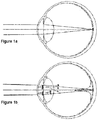
Figure 1 shows the diagram of an eye forming the image of a far point source, focusing on a small proportion of the retina (Figure 1a ) and the result when the light of this beam interacts with non-uniformities of the ocular media and is partially scattered onto the fundus of the eye (Figure 1 b) . -
Figure 2 shows the PSF of an eye with intraocular scattering (Figure 2a ) and the image of an extensive object (uniformly illuminated disc) through this system (Figure 2b ). -
Figure 3 shows a possible version of the proposed double-pass system where an extensive object is projected onto the retina. -
Figure 4 shows how the illumination and the recording can be done through different portions of the pupil of the eye. -
Figure 5 shows two different methods for separating the pupil area into two different portions for the illumination and the recording of the object projected onto the retina.Figure 5a shows two semicircular apertures, whereasFigure 5b shows a circular sub-aperture and a concentric ring. -
Figure 6 shows an example of an extensive object incorporated in the invention which can be generated with a translucent material backlit by independent, LED-type sources. -
Figure 2a shows the PSF of an eye with intraocular scattering.Figure 2b shows the image of a uniformly illuminated disc, such as a particular case of a ring with inner radius 0, through this system. It is verified that if the ratio of energy in a circle having radius R with respect to the total energy of the PSF is Ic (where 0 < Ic < 1), therefore the fraction of the intensity at the center of a disc having radius R with respect to the intensity of an infinite disc is also equal to Ic. This ratio is equal to:
Figure 2a , or of the disc inFigure 2b . In both cases, it is assumed that the PSF is normalized
-
Figure 3 shows a possible implementation of the double-pass system of the invention, in which images are projected sequentially, subtending different visual angles corresponding to different eccentricities of the retina. The extensive object would be a ring having inner radius R0 and outer radius R illuminated by a source S, or a circle like in the example, which is not more than a ring with inner radius R0=0. The light projected by this object can be collimated by the optic C to subsequently be propagated through the scatterer D and filters F. The dimension of the disc can be controlled by the aperture A. The image of this extensive object is projected onto the retina of the eye using lenses L1, L2 and L3. The diaphragm D1 is conjugated with the pupil of the eye (by means of lenses L2 and L3) to enable thus controlling the portion of the pupil through which the object is projected towards the fundus of the eye. - The image of the circle projected onto the retina is recorded using a beam splitter (BS) and lenses L4, L5 and L6. The diaphragm D2 is conjugated with the pupil plane (by means of lenses L4 and L5) to enable thus controlling the portion of the pupil area through which the output light of the eye is recorded. Diaphragms D1 and D2 are arranged such that the projection of the object and the recording are done in different zones of the pupil area, such that light reflected on ocular surfaces is prevented from contributing to the intensity of the image recorded on the camera or the detector. Estimating scattered light is thus not affected by the contribution of back-scatter, "backwardly" scattered light, in the inlet path of the light in the eye, which enables restricting the analysis to forward-scatter, or "forwardly" scattered light, which is the scattered light component directly related to visual quality loss (de Waard, et al. 1992).
-
Figure 4 shows how the illumination and the recording can be done through different portions of the pupil of the eye. The diaphragms do not necessarily have to be circular: the same effect can be achieved with other shapes, such as a ring-shaped mask at the inlet and a central circular shape at the outlet, provided that the diaphragms are different and do not overlap when projected onto the pupil. -
Figure 5 shows two different methods for separating the pupil area into two different portions for the illumination and the recording of the object projected onto the retina.Figure 5a shows two semicircular apertures, whereasFigure 5b shows a circular sub-aperture and a concentric ring. - In reference to the embodiment of
Figure 3 , the extensive object can be generated by a liquid crystal modulator illuminated by a halogen lamp having a broad spectral range, and where the light generated by the source is collimated and homogenized by means of the collimator C and the scatterers D. The spectral filter F allows selecting the spectral profile of the light that will strike the eye. The selected wavelength is preferably 400 nm to 700 nm, with a bandwidth of 5 to 50 nm. The use of a source having a broad spectral range, combined with the use of filters or other elements capable of selecting a specific section of the spectral range, allows estimating intraocular scattering with different wavelengths of the incident light (from red to blue). This characteristic is especially relevant for diagnosing potential pathologies responsible for a specific level of intraocular scattering because analysis of the relationship between the scattered light profile and the incident wavelength allows establishing hypotheses as to the type of scattering centers responsible for intraocular scattering in each case (Coppens, et al. 2005). - The dimensions of the disc are controlled by means of a computerized spatial modulator. An image of the object is projected onto the retina of the eye through lenses L1, L2 and L3. The diaphragm D1 is conjugated with the pupil of the eye (by means of lenses L2 and L3) to enable thus controlling the portion of the pupil through which the object is projected towards the fundus of the eye. The image of the disc projected onto the retina can then be recorded using a beam splitter (BS) and lenses L4, L5 and L6. The diaphragm D2 is conjugated with the pupil plane (by means of lenses L4 and L5) to enable thus controlling the portion of the pupil area through which the output light of the eye is recorded. The diaphragms D1 and D2 can be arranged such that the projection of the object and the recording are done in different zones of the pupil area, such that light reflected on ocular surfaces is prevented from contributing to the intensity of the image recorded on the camera or the detector.
- A series of discs corresponding to visual angles ranging from 0.01 to 10 degrees are projected onto the retina sequentially. The intensity at the center of each disc is recorded. The derivative of this intensity with respect to the radius of the disc is numerically estimated by the finite difference method. The derivative divided by 2π times the angle of each disc is equal to the PSF of the double-pass at the corresponding angle. This can be explained by taking the derivative of Equation 1 (where the PSF is the autocorrelation of the PSF of the system, characteristic of the double-pass), resulting in Equation 2:

- Equation 1 can be approached using finite differences according to:

- The average of the value of the PSF between angles from 0.5 to around 10° is a magnitude that characterizes intraocular scattering (CIE 135-1999).
- If necessary, the PSF corresponding to the single-pass through the ocular media can be numerically calculated from that corresponding to the double-pass and using Fourier treatment-based deconvolution techniques.
- In another embodiment, the extensive object is a translucent film backlit by LEDs as shown in
Figure 6 . The intensity of the light can be homogenized by scatterers D and suitable spacing between diodes. The dimension of the generated disc can be controlled by means of the number of diodes concentrically illuminated. An image of the object is projected onto the retina of the eye through lenses L1, L2 and L3. The diaphragm D1 is conjugated with the pupil of the eye (by means of lenses L2 and L3) to enable thus controlling the portion of the pupil through which the object is projected towards the fundus of the eye. The image of the disc projected onto the retina can be recorded by means such as a CCD camera or a photodetector using a beam splitter (BS) and lenses L4, L5 and L6. The diaphragm D2 is conjugated with the pupil plane (by means of lenses L4 and L5) to enable thus controlling the portion of the pupil area through which the output light of the eye is recorded. The diaphragms D1 and D2 can be arranged such that the projection of the object and the recording are done in different zones of the pupil area, such that light reflected on ocular surfaces is prevented from contributing to the intensity of the image recorded on the camera or the detector. - By illuminating different concentric distributions of LEDS in a controlled manner, a series of discs corresponding to visual angles preferably ranging from 0.01 to 10 degrees are projected onto the retina. The intensity at the center of the recorded image of each disc is recorded in the camera or the detector. Each concentric disc of LEDs is modulated at a specific frequency to be able to discriminate its effect in the subsequent analysis of frequencies. The isolated contribution of each ring on the central area recorded is extracted by means of the spectral analysis of the recorded signal.
- The device of the invention preferably has means for assuring correct alignment of the eye with respect to the optics of the system and means for synchronizing the source and the detector or camera to prevent unnecessary exposures of the retina.
-
- P. M. Prieto, F. Vargas-Martin, S. Goelz, P. Artal, J. Opt. Soc. Am. A, 17, 1388-1398 (2000). "Analysis of the performance of the Hartmann-Shack sensor in the human eye".
- J. F. Díaz-Doutón, A. Benito, J. Pujol, M. Arjona, J.L. Güell, P. Artal, Invest. Ophthalmol. Vis. Sci., 47, 1710-1716 (2006). "Comparison of the retinal image quality with a hartmann-shack wavefront sensor and a double-pass instrument".
- J. Santamaria, P. Artal, and J. Bescós, "Determination of the point-spread function of human eyes using a hybrid optical-digital method," J. Opt. Soc. Am. A 4, 1109-1114 (1987).
- P. Artal, A. Benito, G. M. Pérez, E. Alcón, A. De Casas, J. Pujol, J. M. Marín, "An Objective Scatter Index Based on Double-Pass Retinal Images of a Point Source to Classify Cataracts ", PLoS ONE, 6(2) (2011).
- LN Thibos and X. Hong, "Clinical applications of the Shack-Hartmann aberrometer," Optom. Vision Sci. 76, 817-825 (1999).
- Datiles MB, Ansari RR, Reed GF. (2002) A clinical study of the human lens with a dynamic light scattering device. Exp Eye Res 74:93 9.
- Vivino MA, Chintalagiri S, Trus B, Datiles M (1993) Development of a Scheimpflug slit lamp camera system for quantitative densitometric analysis. Eye 7: 791-798.
- Holladay JT, Prager TC, Trujillo J, Ruiz RS (1987) Brightness acuity test and outdoor visual acuity in cataract patients. J Cataract Refract Surg 13: 67-69.
- J. Bailey, MA Bullimore (1991) A new test for the evaluation of disability glare. Optometry and Vision Science 68, 911-917.
- Van den Berg TJ, IJspeert, JK (1992) Clinical Assessment of Intraocular Stray Light. App. Opt. 31: 3694-3696.
- Franssen L, Coppens JE, van den Berg TJ (2006) Compensation comparison method for assessment of retinal straylight. Invest. Ophthalmol. Vis. Sci. 47: 768-776.
- Van den Berg TJ, van Rijn LJ, Michael R, Heine C, Coeckelbergh T, et al., (2007). Straylight effects with aging and lens extraction. Am. J. Ophthalmol. 144: 358-363.
- De Waard PW, IJspeert JK, van den Berg TJ, de Jong PT, (1992), Intraocular light scattering in age-related cataracts. Invest. Ophthalmol. Vis. Sci. 33: 618-625.
Claims (8)
- Method for measuring ocular scattering comprising the steps of:a. sequentially projecting images from an extensive light source onto the retina, subtending different visual angles corresponding to different eccentricities of the retina; where the extensive light source is a ring having inner radius R0 and outer radius R,b. recording the output light in a camera or photodetector by means of a beam splitter (BS) and lenses once it has passed through the eye twice ; wherein a first diaphragm (D1) is conjugated with the pupil plane before the image is projected onto the retina and a second diaphragm (D2) is conjugated with the pupil plane before the image is recorded to control the portion of the pupil area through which the output light of the eye is recorded, such that the projection of the light source and the recording are done in different zones of the pupil area;c. calculating the intensity at the center of each recorded image;d. reconstructing the broad-field Point Spread Function PSF for each angle from the previously
calculated intensities;e. calculating the average of the value of the PSF between the angles. - Method according to claim 1, where the subtended visual angles range from 0.01 to 10 degrees.
- Method according to any of the preceding claims, where the dimension of the projected image is controlled by means of an aperture (A).
- Method according to any of claims 13, where step a. is performed with a source having a broad spectral range and spectral analysis of the recorded signal is subsequently performed.
- Method according to claim 4, where a wavelength between 400 nm and 700 nm and a bandwidth between 5 nm and 50 nm with a spectral filter is selected.
- Double-pass optoelectronic system comprising an extensive light source configured to sequentially project images onto the retina, subtending different visual angles corresponding to different eccentricities of the retina, wherein the extensive light source is a ring having an inner radius R0 and outer radius R,
a camera or photodetector comprising a beam splitter and lenses configured to record the output light once it has passed through the eye twice;
a first diaphragm (D1) conjugated with the pupil plane before the image is projected onto the retina and a second diaphragm (D2) conjugated with the pupil plane before the image is recorded to control the portion of the pupil area through which the output light is recorded, such that the projection of the light source and the recording are done in different zones of the pupil area,
programming means for calculating the intensity at the center of each recorded image;
reconstructing the broad-field Point Spread Function PSF for each angle from the calculated intensity;
calculating the average of the value of the PSF between the angles. - Double-pass optoelectronic system according to claim 6 wherein the extensive light source is either a liquid crystal modulator illuminated by a halogen lamp having a broad spectral range or a translucent film backlit by LEDs.
- System according to claim 6 or 7, further comprising means for alignment of the eye and means for synchronizing the source and the photodetector or camera to prevent unnecessary exposures of the retina.
Priority Applications (1)
| Application Number | Priority Date | Filing Date | Title |
|---|---|---|---|
| PL12776709T PL2710950T3 (en) | 2011-04-28 | 2012-04-11 | Method and system for measuring intraocular scattering |
Applications Claiming Priority (2)
| Application Number | Priority Date | Filing Date | Title |
|---|---|---|---|
| ES201130670A ES2391192B2 (en) | 2011-04-28 | 2011-04-28 | PROCEDURE AND SYSTEM FOR THE MEASUREMENT OF INTRAOCULAR DISSEMINATION. |
| PCT/ES2012/070242 WO2012146813A1 (en) | 2011-04-28 | 2012-04-11 | Method and system for measuring intraocular scattering |
Publications (3)
| Publication Number | Publication Date |
|---|---|
| EP2710950A1 EP2710950A1 (en) | 2014-03-26 |
| EP2710950A4 EP2710950A4 (en) | 2014-11-19 |
| EP2710950B1 true EP2710950B1 (en) | 2017-05-31 |
Family
ID=47071642
Family Applications (1)
| Application Number | Title | Priority Date | Filing Date |
|---|---|---|---|
| EP12776709.3A Not-in-force EP2710950B1 (en) | 2011-04-28 | 2012-04-11 | Method and system for measuring intraocular scattering |
Country Status (7)
| Country | Link |
|---|---|
| US (1) | US9572490B2 (en) |
| EP (1) | EP2710950B1 (en) |
| DK (1) | DK2710950T3 (en) |
| ES (2) | ES2391192B2 (en) |
| PL (1) | PL2710950T3 (en) |
| PT (1) | PT2710950T (en) |
| WO (1) | WO2012146813A1 (en) |
Families Citing this family (4)
| Publication number | Priority date | Publication date | Assignee | Title |
|---|---|---|---|---|
| ES2441669B2 (en) * | 2012-05-04 | 2015-05-20 | Universitat Politècnica De Catalunya | METHOD FOR DETECTION OF VISUAL FUNCTION LOSSES |
| ES2635064B1 (en) * | 2016-02-29 | 2018-08-16 | Universidad De Murcia | INSTRUMENT FOR OBTAINING IMAGES OF THE EYE AND ASSOCIATED METHOD |
| EP4055553B1 (en) | 2020-01-08 | 2025-10-15 | Haag-Streit Ag | Optical coherence tomography system for ophthalmology |
| WO2021144036A1 (en) | 2020-01-17 | 2021-07-22 | Haag-Streit Ag | Oct-based, spatially resolved transmission measurement of the eye |
Family Cites Families (8)
| Publication number | Priority date | Publication date | Assignee | Title |
|---|---|---|---|---|
| US6659613B2 (en) * | 2000-03-27 | 2003-12-09 | Board Of Regents, The University Of Texas System | Methods and systems for measuring local scattering and aberration properties of optical media |
| EP2177150B1 (en) * | 2000-08-10 | 2014-04-09 | Carl Zeiss Meditec AG | Visual field tester |
| NL1024232C2 (en) * | 2003-09-05 | 2005-03-08 | Konink Nl Akademie Van Wetensc | Method and device for measuring retinal stray light. |
| ES2265225B1 (en) * | 2004-06-15 | 2008-01-01 | Universidad De Murcia | DEVICE AND METHOD FOR DIFFUSION MEASUREMENT (SCATTERING) IN OPTICAL SYSTEMS. |
| SE0401567D0 (en) | 2004-06-17 | 2004-06-17 | Biovelop Internat Bv | Concentration of beta-glucans |
| JP4630107B2 (en) * | 2005-03-31 | 2011-02-09 | 株式会社トプコン | Ophthalmic optical characteristic measuring device |
| US8919960B2 (en) * | 2005-12-20 | 2014-12-30 | James Waller Lambuth Lewis | Adaptive infrared retinoscopic device for detecting ocular aberrations |
| ES2315171B1 (en) | 2007-05-04 | 2010-01-08 | Universitat Politecnica De Catalunya | DEVICE AND METHOD FOR THE MEASUREMENT OF OCULAR DISSEMINATION (SCATTERING) BASED ON THE REGISTRATION AND PROCESSING OF RETINIAN IMAGES. |
-
2011
- 2011-04-28 ES ES201130670A patent/ES2391192B2/en active Active
-
2012
- 2012-04-11 WO PCT/ES2012/070242 patent/WO2012146813A1/en not_active Ceased
- 2012-04-11 PL PL12776709T patent/PL2710950T3/en unknown
- 2012-04-11 US US14/114,354 patent/US9572490B2/en not_active Expired - Fee Related
- 2012-04-11 EP EP12776709.3A patent/EP2710950B1/en not_active Not-in-force
- 2012-04-11 ES ES12776709.3T patent/ES2634453T3/en active Active
- 2012-04-11 PT PT127767093T patent/PT2710950T/en unknown
- 2012-04-11 DK DK12776709.3T patent/DK2710950T3/en active
Non-Patent Citations (1)
| Title |
|---|
| None * |
Also Published As
| Publication number | Publication date |
|---|---|
| US20140211154A1 (en) | 2014-07-31 |
| US9572490B2 (en) | 2017-02-21 |
| ES2634453T3 (en) | 2017-09-27 |
| DK2710950T3 (en) | 2017-08-07 |
| EP2710950A4 (en) | 2014-11-19 |
| ES2391192B2 (en) | 2013-06-18 |
| EP2710950A1 (en) | 2014-03-26 |
| PT2710950T (en) | 2017-07-13 |
| ES2391192A1 (en) | 2012-11-22 |
| PL2710950T3 (en) | 2018-01-31 |
| WO2012146813A1 (en) | 2012-11-01 |
Similar Documents
| Publication | Publication Date | Title |
|---|---|---|
| Ginis et al. | The wide-angle point spread function of the human eye reconstructed by a new optical method | |
| JP4464726B2 (en) | Ophthalmic equipment | |
| Pinero et al. | Ocular scattering | |
| US8488851B2 (en) | System and method for measuring light scattering in the eyeball or eye region by recording and processing retinal images | |
| Ginis et al. | Wavelength dependence of the ocular straylight | |
| US9532713B2 (en) | Method and device for high-resolution retinal imaging | |
| JP2008246153A (en) | Optometry apparatus and method thereof | |
| JPWO2003022138A1 (en) | Eye optical characteristics measuring device | |
| EP1659929B1 (en) | Method and device for measuring retinal stray light | |
| Castro et al. | New testing software for quantifying discrimination capacity in subjects with ocular pathologies | |
| US9572490B2 (en) | Method and system for measuring intraocular scattering | |
| Vera-Díaz et al. | The human eye and adaptive optics | |
| JP4652558B2 (en) | Optical property measuring device | |
| JP2002233502A (en) | Contrast chart device | |
| JP7420476B2 (en) | Ophthalmological apparatus, control method thereof, ophthalmological information processing apparatus, control method thereof, program, and recording medium | |
| Miller et al. | Glare sensitivity related to use of contact lenses | |
| Bhattarai | Application of Bessel beams in the human eye | |
| Rizzieri et al. | Merits of vision in presence of light scattering using Tiffen ProMist filters | |
| Ginis et al. | The wide-angle point spread function of the human eye | |
| Neves | Analysis of light visual distortion and quality of vision with different multifocal lens designs for the compensation of presbyopia | |
| ES2688769B2 (en) | Method for measuring intraocular diffusion that affects different ocular media of the eye and computer program products thereof | |
| López | Measuring and Modelling Forward Light Scattering in the Human Eye | |
| Vilaseca | Speckle reduction in double-pass retinal images | |
| Santos Vives | Novel system for measuring the scattering of the cornea and the lens | |
| WO2023230436A2 (en) | Methods and systems for the diagnosis of cataracts, light scattering, and refractive errors in human eyes |
Legal Events
| Date | Code | Title | Description |
|---|---|---|---|
| PUAI | Public reference made under article 153(3) epc to a published international application that has entered the european phase |
Free format text: ORIGINAL CODE: 0009012 |
|
| 17P | Request for examination filed |
Effective date: 20131128 |
|
| AK | Designated contracting states |
Kind code of ref document: A1 Designated state(s): AL AT BE BG CH CY CZ DE DK EE ES FI FR GB GR HR HU IE IS IT LI LT LU LV MC MK MT NL NO PL PT RO RS SE SI SK SM TR |
|
| DAX | Request for extension of the european patent (deleted) | ||
| A4 | Supplementary search report drawn up and despatched |
Effective date: 20141020 |
|
| RIC1 | Information provided on ipc code assigned before grant |
Ipc: A61B 3/10 20060101AFI20141014BHEP Ipc: A61B 3/103 20060101ALI20141014BHEP |
|
| 17Q | First examination report despatched |
Effective date: 20160623 |
|
| GRAP | Despatch of communication of intention to grant a patent |
Free format text: ORIGINAL CODE: EPIDOSNIGR1 |
|
| STAA | Information on the status of an ep patent application or granted ep patent |
Free format text: STATUS: GRANT OF PATENT IS INTENDED |
|
| GRAS | Grant fee paid |
Free format text: ORIGINAL CODE: EPIDOSNIGR3 |
|
| INTG | Intention to grant announced |
Effective date: 20170222 |
|
| GRAA | (expected) grant |
Free format text: ORIGINAL CODE: 0009210 |
|
| STAA | Information on the status of an ep patent application or granted ep patent |
Free format text: STATUS: THE PATENT HAS BEEN GRANTED |
|
| AK | Designated contracting states |
Kind code of ref document: B1 Designated state(s): AL AT BE BG CH CY CZ DE DK EE ES FI FR GB GR HR HU IE IS IT LI LT LU LV MC MK MT NL NO PL PT RO RS SE SI SK SM TR |
|
| REG | Reference to a national code |
Ref country code: CH Ref legal event code: EP Ref country code: GB Ref legal event code: FG4D |
|
| REG | Reference to a national code |
Ref country code: AT Ref legal event code: REF Ref document number: 896689 Country of ref document: AT Kind code of ref document: T Effective date: 20170615 |
|
| REG | Reference to a national code |
Ref country code: IE Ref legal event code: FG4D |
|
| REG | Reference to a national code |
Ref country code: DE Ref legal event code: R096 Ref document number: 602012033012 Country of ref document: DE Ref country code: PT Ref legal event code: SC4A Ref document number: 2710950 Country of ref document: PT Date of ref document: 20170713 Kind code of ref document: T Free format text: AVAILABILITY OF NATIONAL TRANSLATION Effective date: 20170707 |
|
| REG | Reference to a national code |
Ref country code: NL Ref legal event code: FP |
|
| REG | Reference to a national code |
Ref country code: NO Ref legal event code: T2 Effective date: 20170531 Ref country code: DK Ref legal event code: T3 Effective date: 20170803 |
|
| REG | Reference to a national code |
Ref country code: SE Ref legal event code: TRGR |
|
| REG | Reference to a national code |
Ref country code: ES Ref legal event code: FG2A Ref document number: 2634453 Country of ref document: ES Kind code of ref document: T3 Effective date: 20170927 |
|
| REG | Reference to a national code |
Ref country code: CH Ref legal event code: NV Representative=s name: SCHMAUDER AND PARTNER AG PATENT- UND MARKENANW, CH |
|
| REG | Reference to a national code |
Ref country code: LT Ref legal event code: MG4D |
|
| PG25 | Lapsed in a contracting state [announced via postgrant information from national office to epo] |
Ref country code: LT Free format text: LAPSE BECAUSE OF FAILURE TO SUBMIT A TRANSLATION OF THE DESCRIPTION OR TO PAY THE FEE WITHIN THE PRESCRIBED TIME-LIMIT Effective date: 20170531 Ref country code: HR Free format text: LAPSE BECAUSE OF FAILURE TO SUBMIT A TRANSLATION OF THE DESCRIPTION OR TO PAY THE FEE WITHIN THE PRESCRIBED TIME-LIMIT Effective date: 20170531 |
|
| PG25 | Lapsed in a contracting state [announced via postgrant information from national office to epo] |
Ref country code: LV Free format text: LAPSE BECAUSE OF FAILURE TO SUBMIT A TRANSLATION OF THE DESCRIPTION OR TO PAY THE FEE WITHIN THE PRESCRIBED TIME-LIMIT Effective date: 20170531 Ref country code: RS Free format text: LAPSE BECAUSE OF FAILURE TO SUBMIT A TRANSLATION OF THE DESCRIPTION OR TO PAY THE FEE WITHIN THE PRESCRIBED TIME-LIMIT Effective date: 20170531 Ref country code: BG Free format text: LAPSE BECAUSE OF FAILURE TO SUBMIT A TRANSLATION OF THE DESCRIPTION OR TO PAY THE FEE WITHIN THE PRESCRIBED TIME-LIMIT Effective date: 20170831 Ref country code: IS Free format text: LAPSE BECAUSE OF FAILURE TO SUBMIT A TRANSLATION OF THE DESCRIPTION OR TO PAY THE FEE WITHIN THE PRESCRIBED TIME-LIMIT Effective date: 20170930 |
|
| PG25 | Lapsed in a contracting state [announced via postgrant information from national office to epo] |
Ref country code: RO Free format text: LAPSE BECAUSE OF FAILURE TO SUBMIT A TRANSLATION OF THE DESCRIPTION OR TO PAY THE FEE WITHIN THE PRESCRIBED TIME-LIMIT Effective date: 20170531 Ref country code: EE Free format text: LAPSE BECAUSE OF FAILURE TO SUBMIT A TRANSLATION OF THE DESCRIPTION OR TO PAY THE FEE WITHIN THE PRESCRIBED TIME-LIMIT Effective date: 20170531 Ref country code: SK Free format text: LAPSE BECAUSE OF FAILURE TO SUBMIT A TRANSLATION OF THE DESCRIPTION OR TO PAY THE FEE WITHIN THE PRESCRIBED TIME-LIMIT Effective date: 20170531 |
|
| PG25 | Lapsed in a contracting state [announced via postgrant information from national office to epo] |
Ref country code: SM Free format text: LAPSE BECAUSE OF FAILURE TO SUBMIT A TRANSLATION OF THE DESCRIPTION OR TO PAY THE FEE WITHIN THE PRESCRIBED TIME-LIMIT Effective date: 20170531 |
|
| REG | Reference to a national code |
Ref country code: DE Ref legal event code: R097 Ref document number: 602012033012 Country of ref document: DE |
|
| PLBE | No opposition filed within time limit |
Free format text: ORIGINAL CODE: 0009261 |
|
| STAA | Information on the status of an ep patent application or granted ep patent |
Free format text: STATUS: NO OPPOSITION FILED WITHIN TIME LIMIT |
|
| REG | Reference to a national code |
Ref country code: FR Ref legal event code: PLFP Year of fee payment: 7 |
|
| 26N | No opposition filed |
Effective date: 20180301 |
|
| PG25 | Lapsed in a contracting state [announced via postgrant information from national office to epo] |
Ref country code: SI Free format text: LAPSE BECAUSE OF FAILURE TO SUBMIT A TRANSLATION OF THE DESCRIPTION OR TO PAY THE FEE WITHIN THE PRESCRIBED TIME-LIMIT Effective date: 20170531 |
|
| PG25 | Lapsed in a contracting state [announced via postgrant information from national office to epo] |
Ref country code: MC Free format text: LAPSE BECAUSE OF FAILURE TO SUBMIT A TRANSLATION OF THE DESCRIPTION OR TO PAY THE FEE WITHIN THE PRESCRIBED TIME-LIMIT Effective date: 20170531 |
|
| PG25 | Lapsed in a contracting state [announced via postgrant information from national office to epo] |
Ref country code: LU Free format text: LAPSE BECAUSE OF NON-PAYMENT OF DUE FEES Effective date: 20180411 |
|
| REG | Reference to a national code |
Ref country code: AT Ref legal event code: UEP Ref document number: 896689 Country of ref document: AT Kind code of ref document: T Effective date: 20170531 |
|
| PG25 | Lapsed in a contracting state [announced via postgrant information from national office to epo] |
Ref country code: MT Free format text: LAPSE BECAUSE OF NON-PAYMENT OF DUE FEES Effective date: 20180411 |
|
| PGFP | Annual fee paid to national office [announced via postgrant information from national office to epo] |
Ref country code: PL Payment date: 20200326 Year of fee payment: 9 |
|
| PG25 | Lapsed in a contracting state [announced via postgrant information from national office to epo] |
Ref country code: HU Free format text: LAPSE BECAUSE OF FAILURE TO SUBMIT A TRANSLATION OF THE DESCRIPTION OR TO PAY THE FEE WITHIN THE PRESCRIBED TIME-LIMIT; INVALID AB INITIO Effective date: 20120411 |
|
| PG25 | Lapsed in a contracting state [announced via postgrant information from national office to epo] |
Ref country code: CY Free format text: LAPSE BECAUSE OF FAILURE TO SUBMIT A TRANSLATION OF THE DESCRIPTION OR TO PAY THE FEE WITHIN THE PRESCRIBED TIME-LIMIT Effective date: 20170531 Ref country code: MK Free format text: LAPSE BECAUSE OF NON-PAYMENT OF DUE FEES Effective date: 20170531 |
|
| PGFP | Annual fee paid to national office [announced via postgrant information from national office to epo] |
Ref country code: TR Payment date: 20200331 Year of fee payment: 9 |
|
| PG25 | Lapsed in a contracting state [announced via postgrant information from national office to epo] |
Ref country code: AL Free format text: LAPSE BECAUSE OF FAILURE TO SUBMIT A TRANSLATION OF THE DESCRIPTION OR TO PAY THE FEE WITHIN THE PRESCRIBED TIME-LIMIT Effective date: 20170531 |
|
| PGFP | Annual fee paid to national office [announced via postgrant information from national office to epo] |
Ref country code: PT Payment date: 20200401 Year of fee payment: 9 Ref country code: FI Payment date: 20200429 Year of fee payment: 9 Ref country code: DK Payment date: 20200430 Year of fee payment: 9 Ref country code: CH Payment date: 20200506 Year of fee payment: 9 Ref country code: NL Payment date: 20200403 Year of fee payment: 9 Ref country code: GR Payment date: 20200430 Year of fee payment: 9 Ref country code: CZ Payment date: 20200401 Year of fee payment: 9 Ref country code: NO Payment date: 20200430 Year of fee payment: 9 Ref country code: IE Payment date: 20200429 Year of fee payment: 9 |
|
| PGFP | Annual fee paid to national office [announced via postgrant information from national office to epo] |
Ref country code: SE Payment date: 20200429 Year of fee payment: 9 |
|
| PGFP | Annual fee paid to national office [announced via postgrant information from national office to epo] |
Ref country code: AT Payment date: 20200414 Year of fee payment: 9 |
|
| REG | Reference to a national code |
Ref country code: FI Ref legal event code: MAE |
|
| REG | Reference to a national code |
Ref country code: DK Ref legal event code: EBP Effective date: 20210430 |
|
| REG | Reference to a national code |
Ref country code: NO Ref legal event code: MMEP |
|
| REG | Reference to a national code |
Ref country code: SE Ref legal event code: EUG |
|
| REG | Reference to a national code |
Ref country code: NL Ref legal event code: MM Effective date: 20210501 |
|
| REG | Reference to a national code |
Ref country code: AT Ref legal event code: MM01 Ref document number: 896689 Country of ref document: AT Kind code of ref document: T Effective date: 20210411 |
|
| PG25 | Lapsed in a contracting state [announced via postgrant information from national office to epo] |
Ref country code: CZ Free format text: LAPSE BECAUSE OF NON-PAYMENT OF DUE FEES Effective date: 20210411 Ref country code: SE Free format text: LAPSE BECAUSE OF NON-PAYMENT OF DUE FEES Effective date: 20210412 Ref country code: PT Free format text: LAPSE BECAUSE OF NON-PAYMENT OF DUE FEES Effective date: 20211011 Ref country code: NO Free format text: LAPSE BECAUSE OF NON-PAYMENT OF DUE FEES Effective date: 20210430 Ref country code: FI Free format text: LAPSE BECAUSE OF NON-PAYMENT OF DUE FEES Effective date: 20210411 Ref country code: AT Free format text: LAPSE BECAUSE OF NON-PAYMENT OF DUE FEES Effective date: 20210411 Ref country code: CH Free format text: LAPSE BECAUSE OF NON-PAYMENT OF DUE FEES Effective date: 20210430 Ref country code: LI Free format text: LAPSE BECAUSE OF NON-PAYMENT OF DUE FEES Effective date: 20210430 |
|
| PG25 | Lapsed in a contracting state [announced via postgrant information from national office to epo] |
Ref country code: GR Free format text: LAPSE BECAUSE OF NON-PAYMENT OF DUE FEES Effective date: 20211108 |
|
| PG25 | Lapsed in a contracting state [announced via postgrant information from national office to epo] |
Ref country code: NL Free format text: LAPSE BECAUSE OF NON-PAYMENT OF DUE FEES Effective date: 20210501 |
|
| PG25 | Lapsed in a contracting state [announced via postgrant information from national office to epo] |
Ref country code: IE Free format text: LAPSE BECAUSE OF NON-PAYMENT OF DUE FEES Effective date: 20210411 Ref country code: DK Free format text: LAPSE BECAUSE OF NON-PAYMENT OF DUE FEES Effective date: 20210430 |
|
| PG25 | Lapsed in a contracting state [announced via postgrant information from national office to epo] |
Ref country code: PL Free format text: LAPSE BECAUSE OF NON-PAYMENT OF DUE FEES Effective date: 20210411 |
|
| PGFP | Annual fee paid to national office [announced via postgrant information from national office to epo] |
Ref country code: IT Payment date: 20230426 Year of fee payment: 12 Ref country code: FR Payment date: 20230425 Year of fee payment: 12 Ref country code: ES Payment date: 20230508 Year of fee payment: 12 Ref country code: DE Payment date: 20230428 Year of fee payment: 12 |
|
| PGFP | Annual fee paid to national office [announced via postgrant information from national office to epo] |
Ref country code: BE Payment date: 20230425 Year of fee payment: 12 |
|
| PGFP | Annual fee paid to national office [announced via postgrant information from national office to epo] |
Ref country code: GB Payment date: 20230428 Year of fee payment: 12 |
|
| PG25 | Lapsed in a contracting state [announced via postgrant information from national office to epo] |
Ref country code: TR Free format text: LAPSE BECAUSE OF NON-PAYMENT OF DUE FEES Effective date: 20210411 |
|
| REG | Reference to a national code |
Ref country code: DE Ref legal event code: R119 Ref document number: 602012033012 Country of ref document: DE |
|
| GBPC | Gb: european patent ceased through non-payment of renewal fee |
Effective date: 20240411 |
|
| REG | Reference to a national code |
Ref country code: BE Ref legal event code: MM Effective date: 20240430 |
|
| PG25 | Lapsed in a contracting state [announced via postgrant information from national office to epo] |
Ref country code: DE Free format text: LAPSE BECAUSE OF NON-PAYMENT OF DUE FEES Effective date: 20241105 |
|
| PG25 | Lapsed in a contracting state [announced via postgrant information from national office to epo] |
Ref country code: BE Free format text: LAPSE BECAUSE OF NON-PAYMENT OF DUE FEES Effective date: 20240430 |
|
| PG25 | Lapsed in a contracting state [announced via postgrant information from national office to epo] |
Ref country code: GB Free format text: LAPSE BECAUSE OF NON-PAYMENT OF DUE FEES Effective date: 20240411 |
|
| PG25 | Lapsed in a contracting state [announced via postgrant information from national office to epo] |
Ref country code: FR Free format text: LAPSE BECAUSE OF NON-PAYMENT OF DUE FEES Effective date: 20240430 |
|
| PG25 | Lapsed in a contracting state [announced via postgrant information from national office to epo] |
Ref country code: GB Free format text: LAPSE BECAUSE OF NON-PAYMENT OF DUE FEES Effective date: 20240411 Ref country code: FR Free format text: LAPSE BECAUSE OF NON-PAYMENT OF DUE FEES Effective date: 20240430 Ref country code: DE Free format text: LAPSE BECAUSE OF NON-PAYMENT OF DUE FEES Effective date: 20241105 Ref country code: BE Free format text: LAPSE BECAUSE OF NON-PAYMENT OF DUE FEES Effective date: 20240430 |
|
| PG25 | Lapsed in a contracting state [announced via postgrant information from national office to epo] |
Ref country code: IT Free format text: LAPSE BECAUSE OF NON-PAYMENT OF DUE FEES Effective date: 20240411 |
|
| REG | Reference to a national code |
Ref country code: ES Ref legal event code: FD2A Effective date: 20250528 |
|
| PG25 | Lapsed in a contracting state [announced via postgrant information from national office to epo] |
Ref country code: ES Free format text: LAPSE BECAUSE OF NON-PAYMENT OF DUE FEES Effective date: 20240412 |