EP2710335B1 - Optical sensor - Google Patents
Optical sensor Download PDFInfo
- Publication number
- EP2710335B1 EP2710335B1 EP12722142.2A EP12722142A EP2710335B1 EP 2710335 B1 EP2710335 B1 EP 2710335B1 EP 12722142 A EP12722142 A EP 12722142A EP 2710335 B1 EP2710335 B1 EP 2710335B1
- Authority
- EP
- European Patent Office
- Prior art keywords
- measurement
- interferometer
- interferometers
- laser
- light
- Prior art date
- Legal status (The legal status is an assumption and is not a legal conclusion. Google has not performed a legal analysis and makes no representation as to the accuracy of the status listed.)
- Active
Links
Images


Classifications
-
- G—PHYSICS
- G01—MEASURING; TESTING
- G01D—MEASURING NOT SPECIALLY ADAPTED FOR A SPECIFIC VARIABLE; ARRANGEMENTS FOR MEASURING TWO OR MORE VARIABLES NOT COVERED IN A SINGLE OTHER SUBCLASS; TARIFF METERING APPARATUS; MEASURING OR TESTING NOT OTHERWISE PROVIDED FOR
- G01D5/00—Mechanical means for transferring the output of a sensing member; Means for converting the output of a sensing member to another variable where the form or nature of the sensing member does not constrain the means for converting; Transducers not specially adapted for a specific variable
- G01D5/26—Mechanical means for transferring the output of a sensing member; Means for converting the output of a sensing member to another variable where the form or nature of the sensing member does not constrain the means for converting; Transducers not specially adapted for a specific variable characterised by optical transfer means, i.e. using infrared, visible, or ultraviolet light
-
- G—PHYSICS
- G01—MEASURING; TESTING
- G01L—MEASURING FORCE, STRESS, TORQUE, WORK, MECHANICAL POWER, MECHANICAL EFFICIENCY, OR FLUID PRESSURE
- G01L11/00—Measuring steady or quasi-steady pressure of a fluid or a fluent solid material by means not provided for in group G01L7/00 or G01L9/00
- G01L11/02—Measuring steady or quasi-steady pressure of a fluid or a fluent solid material by means not provided for in group G01L7/00 or G01L9/00 by optical means
-
- G—PHYSICS
- G01—MEASURING; TESTING
- G01D—MEASURING NOT SPECIALLY ADAPTED FOR A SPECIFIC VARIABLE; ARRANGEMENTS FOR MEASURING TWO OR MORE VARIABLES NOT COVERED IN A SINGLE OTHER SUBCLASS; TARIFF METERING APPARATUS; MEASURING OR TESTING NOT OTHERWISE PROVIDED FOR
- G01D5/00—Mechanical means for transferring the output of a sensing member; Means for converting the output of a sensing member to another variable where the form or nature of the sensing member does not constrain the means for converting; Transducers not specially adapted for a specific variable
- G01D5/26—Mechanical means for transferring the output of a sensing member; Means for converting the output of a sensing member to another variable where the form or nature of the sensing member does not constrain the means for converting; Transducers not specially adapted for a specific variable characterised by optical transfer means, i.e. using infrared, visible, or ultraviolet light
- G01D5/266—Mechanical means for transferring the output of a sensing member; Means for converting the output of a sensing member to another variable where the form or nature of the sensing member does not constrain the means for converting; Transducers not specially adapted for a specific variable characterised by optical transfer means, i.e. using infrared, visible, or ultraviolet light by interferometric means
-
- G—PHYSICS
- G01—MEASURING; TESTING
- G01B—MEASURING LENGTH, THICKNESS OR SIMILAR LINEAR DIMENSIONS; MEASURING ANGLES; MEASURING AREAS; MEASURING IRREGULARITIES OF SURFACES OR CONTOURS
- G01B11/00—Measuring arrangements characterised by the use of optical techniques
-
- G—PHYSICS
- G01—MEASURING; TESTING
- G01B—MEASURING LENGTH, THICKNESS OR SIMILAR LINEAR DIMENSIONS; MEASURING ANGLES; MEASURING AREAS; MEASURING IRREGULARITIES OF SURFACES OR CONTOURS
- G01B9/00—Measuring instruments characterised by the use of optical techniques
- G01B9/02—Interferometers
- G01B9/02055—Reduction or prevention of errors; Testing; Calibration
- G01B9/0207—Error reduction by correction of the measurement signal based on independently determined error sources, e.g. using a reference interferometer
-
- G—PHYSICS
- G01—MEASURING; TESTING
- G01H—MEASUREMENT OF MECHANICAL VIBRATIONS OR ULTRASONIC, SONIC OR INFRASONIC WAVES
- G01H9/00—Measuring mechanical vibrations or ultrasonic, sonic or infrasonic waves by using radiation-sensitive means, e.g. optical means
-
- G—PHYSICS
- G02—OPTICS
- G02F—OPTICAL DEVICES OR ARRANGEMENTS FOR THE CONTROL OF LIGHT BY MODIFICATION OF THE OPTICAL PROPERTIES OF THE MEDIA OF THE ELEMENTS INVOLVED THEREIN; NON-LINEAR OPTICS; FREQUENCY-CHANGING OF LIGHT; OPTICAL LOGIC ELEMENTS; OPTICAL ANALOGUE/DIGITAL CONVERTERS
- G02F1/00—Devices or arrangements for the control of the intensity, colour, phase, polarisation or direction of light arriving from an independent light source, e.g. switching, gating or modulating; Non-linear optics
- G02F1/01—Devices or arrangements for the control of the intensity, colour, phase, polarisation or direction of light arriving from an independent light source, e.g. switching, gating or modulating; Non-linear optics for the control of the intensity, phase, polarisation or colour
- G02F1/21—Devices or arrangements for the control of the intensity, colour, phase, polarisation or direction of light arriving from an independent light source, e.g. switching, gating or modulating; Non-linear optics for the control of the intensity, phase, polarisation or colour by interference
-
- H—ELECTRICITY
- H04—ELECTRIC COMMUNICATION TECHNIQUE
- H04R—LOUDSPEAKERS, MICROPHONES, GRAMOPHONE PICK-UPS OR LIKE ACOUSTIC ELECTROMECHANICAL TRANSDUCERS; ELECTRIC HEARING AIDS; PUBLIC ADDRESS SYSTEMS
- H04R23/00—Transducers other than those covered by groups H04R9/00 - H04R21/00
- H04R23/008—Transducers other than those covered by groups H04R9/00 - H04R21/00 using optical signals for detecting or generating sound
-
- G—PHYSICS
- G01—MEASURING; TESTING
- G01B—MEASURING LENGTH, THICKNESS OR SIMILAR LINEAR DIMENSIONS; MEASURING ANGLES; MEASURING AREAS; MEASURING IRREGULARITIES OF SURFACES OR CONTOURS
- G01B9/00—Measuring instruments characterised by the use of optical techniques
- G01B9/02—Interferometers
-
- G—PHYSICS
- G02—OPTICS
- G02F—OPTICAL DEVICES OR ARRANGEMENTS FOR THE CONTROL OF LIGHT BY MODIFICATION OF THE OPTICAL PROPERTIES OF THE MEDIA OF THE ELEMENTS INVOLVED THEREIN; NON-LINEAR OPTICS; FREQUENCY-CHANGING OF LIGHT; OPTICAL LOGIC ELEMENTS; OPTICAL ANALOGUE/DIGITAL CONVERTERS
- G02F1/00—Devices or arrangements for the control of the intensity, colour, phase, polarisation or direction of light arriving from an independent light source, e.g. switching, gating or modulating; Non-linear optics
- G02F1/01—Devices or arrangements for the control of the intensity, colour, phase, polarisation or direction of light arriving from an independent light source, e.g. switching, gating or modulating; Non-linear optics for the control of the intensity, phase, polarisation or colour
- G02F1/21—Devices or arrangements for the control of the intensity, colour, phase, polarisation or direction of light arriving from an independent light source, e.g. switching, gating or modulating; Non-linear optics for the control of the intensity, phase, polarisation or colour by interference
- G02F1/216—Devices or arrangements for the control of the intensity, colour, phase, polarisation or direction of light arriving from an independent light source, e.g. switching, gating or modulating; Non-linear optics for the control of the intensity, phase, polarisation or colour by interference using liquid crystals, e.g. liquid crystal Fabry-Perot filters
Definitions
- a device comprising measurement and reference interferometers, each configured to receive light from the same light source and to emit light to respective detectors and having a respective operating point, wherein the measurement interferometer is configured to respond to variations in a physical parameter by varying the intensity of light emitted, whereas the reference interferometer Is configured to be unresponsive to variations in the physical parameter, the device further comprising a signal processor for generating a difference output signal depending on respective output signals generated by the detectors.
- both interferometers will be affected by fluctuations in the light from the light source, but only the measurement interferometer will be influenced by changes in the physical parameter; the reference interferometer is isolated from these changes.
- the interference pattern in the reference interferometer thus represents the noise from the light source only as does the signal from its respective detector. This signal can be used to compensate for noise from the light source in the signal from the measurement interferometer's respective detector, such that the signal represents changes in the physical parameter only.
- the SNR is therefore increased, and furthermore, the device may be made to be very compact since the only additional component required is the reference interferometer.
- the measurement and/or reference interferometers may comprise a pair of spaced apart mirrors, preferably mechanically rigid and/or Immovable mirrors.
- the mirrors may both be plane mirrors or curved mirrors or may comprise one plane and one curved mirror.
- Tuning electrodes 4 are disposed adjacent the reference Fabry-Perot etalon 3 and are used to influence its transmission characteristics in a way that a favourable operating point is established. This operating point usually is the inflexion point of the transmission function of the reference Fabry-Perot etalon 3. These electrodes 4 influence the transmission characteristics by way of an electro-optic or thermo-optical effect. Alternatively, thin film resistors or Peltier elements can be used in place of the tuning electrodes 4. These make use of a thermal or thermo-optical effect to change the transmission characteristics of the reference Fabry-Perot etalon 3 thermally.
- the light from the laser source 1 is also incident on a measurement Fabry-Perot etalon 7, which is influenced by changes in a physical parameter (for example, air pressure).
- a physical parameter for example, air pressure
- the exact manner in which the measurement Fabry-Perot etalon 7 is caused to interact with the environment so as to be influenced by the physical parameter will depend on the nature of the physical parameter. In the case of air pressure, the measurement Fabry-Perot etalon 7 will simply have a cavity that is coupled to the air through an aperture. This will become clearer below.
- the emerging light from the measurement Fabry-Perot etalon 7 is also detected by a photodetector (not shown), for example a PIN diode.
- the output signal from this photodetector will depend on the fluctuations In the physical parameter to be measured and on noise from the laser source 1.
- a difference signal between the output signal from this photodetector and the output signal from photodetector 6 is generated by a difference amplifier 8. By this means, common mode laser noise from laser source 1 is cancelled.
- the difference amplifier 8 In order to dynamically adjust the DC levels from both the reference path (i.e. through reference Fabry-Perot etalon 3 and photodetector 6) and the measurement path (i.e. through measurement Fabry-Perot etalon 7 and its photodetector), the difference amplifier 8 has a preceding gain stage where both output signals are dynamically adjusted with a long time constant.
- the light from laser source 1 may be caused to impinge on both etalons 3, 7 by way of a beam splitter. Alternatively, a double-sided emission laser source may be used.
- the tuning electrodes 4 and liquid crystal 5 are omitted.
- the laser source 1 is operated in pulses, alternating between the measurement path and the reference path such that successive pulses are incident on one or the other (but not both) of the reference and measurement Fabry-Perot etalons 3, 7. In this switching mode, the operating point can be set by adjusting the current of the laser source 1 power supply.
- the optical microphone of Figure 2 It is possible to manufacture the optical microphone of Figure 2 using silicon on insulator (SOI) techniques.
- SOI silicon on insulator
- a major advantage of the waveguide structure 13 is the possibility to integrate the reference path so that it has small physical dimensions; the reference Fabry-Perot etalon may have dimensions of typically 1 ⁇ m to 1 mm (length) and 1 ⁇ m (width).
- a laser diode with double-sided emission 30 embedded in a substrate 31 is employed.
- This laser diode 30 can be a vertical cavity surface- emitting laser (VCSEL).
- the VCSEL can either be modified by partial removal of the substrate to allow light to be emitted from both the front and the rear sides, or, a double-sided emission can be specially manufactured by omitting part of the substrate.
- Another device that can be used (again, either by modification or special manufacture) for double-sided emission Is a distributed feedback (DFB) laser diode.
- DFB distributed feedback
- the layers of the stack can consist of glass, polymer, silicon or other dielectric layers, depending on the wavelength of light emitted by laser diode 30 and the desired mechanical processing properties. Also a combination of materials in the stack is possible. The layers may be combined using bonding, gluing or other technologies.
- One of the emerging laser beams is incident on a reference path; the other laser beam, emitted from the opposite side is incident on a measurement path.
Landscapes
- Physics & Mathematics (AREA)
- General Physics & Mathematics (AREA)
- Nonlinear Science (AREA)
- Engineering & Computer Science (AREA)
- Acoustics & Sound (AREA)
- Signal Processing (AREA)
- Optics & Photonics (AREA)
- Instruments For Measurement Of Length By Optical Means (AREA)
- Mechanical Light Control Or Optical Switches (AREA)
- Length Measuring Devices By Optical Means (AREA)
- Investigating Or Analysing Materials By Optical Means (AREA)
- Spectrometry And Color Measurement (AREA)
Description
- The invention relates to a device comprising measurement and reference interferometers, which can be used to form an optical sensor. It also relates to an optical microphone comprising such a device.
- Various types of optical sensor make use of interferometers to detect changes in a physical parameter. In such sensors, light from a laser is coupled into an interferometer, which is influenced by changes in the physical parameter to produce corresponding changes in the interference pattern. These changes in the interference pattern manifest as changes in intensity, which can be detected by a photodetector, Various different physical parameters can be used to cause a change in the interference pattern and hence can be sensed by this type of sensor. Examples include pressure (including air pressure), strain and displacement.
- The signal-to-noise ratio (SNR) of such sensors is often limited by noise caused by fluctuations in intensity or frequency of the light output from the laser. There are various methods for stabilising laser frequency. For example, one method makes use of a Fabry-Perot interferometer or etalon to generate an error signal. The etalon converts frequency fluctuations into intensity fluctuations, which can be detected by a photodetector. The resulting photocurrent is used as a feedback signal, which can either act on the laser supply current or move a cavity mirror, for example, to correct the frequency fluctuations.
- However, this kind of arrangement is bulky and expensive. It is incompatible with many applications where use of optical sensors would be desirable. For example, in mobile communication devices, microphones are required that are highly stable and resistant to shock, insusceptible to wind noise. These features can all be provided by an optical microphone making use of a laser light source and interferometer since these do not have moving parts, such as a membrane. However, it is also required that such microphones are compact and have a high SNR. Whilst the stabilisation technique referred to above can compensate for laser frequency noise to a certain extent, it cannot compensate of relative intensity noise.
- According to the invention, there is provided a device comprising measurement and reference interferometers, each configured to receive light from the same light source and to emit light to respective detectors and having a respective operating point, wherein the measurement interferometer is configured to respond to variations in a physical parameter by varying the intensity of light emitted, whereas the reference interferometer Is configured to be unresponsive to variations in the physical parameter, the device further comprising a signal processor for generating a difference output signal depending on respective output signals generated by the detectors.
- Light from the same light source is coupled into both a reference interferometer that is insensitive or unresponsive to variations in a physical parameter to be sensed and into a measurement interferometer that is responsive to such variations. Therefore, both interferometers will be affected by fluctuations in the light from the light source, but only the measurement interferometer will be influenced by changes in the physical parameter; the reference interferometer is isolated from these changes. The interference pattern in the reference interferometer thus represents the noise from the light source only as does the signal from its respective detector. This signal can be used to compensate for noise from the light source in the signal from the measurement interferometer's respective detector, such that the signal represents changes in the physical parameter only. The SNR is therefore increased, and furthermore, the device may be made to be very compact since the only additional component required is the reference interferometer.
- The operating point of each of the reference and measurement interferometer is selected to achieve a linear variation of the transmission of the interferometer with frequency.
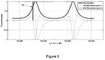
Figure 5 shows a graph of the transmission (normallsed to a maximum value of 1) against a parameter "q", where q=4πnd/λ (n is refractive index in the interferometer cavity; d is the spacing between the interferometer mirrors; and A is the wavelength of light). The parameter q is of course proportional to the frequency of light. The relationship between transmission and q is represented by the so-called "Airy function".Figure 5 also shows graphs of the first and second derivatives of the transmission versus q graph. The best linearity of the transmission versus q Is found at a point where the second derivative is zero. The point where the second derivative of the relationship of transmission with q is zero is therefore preferably selected as the operating point for each interferometer. - The operating points are likely to be different for each interferometer as even a small change in size of the interferometers will influence the optimum position of the operating points.
- An alternative operating point that can be used is to tune the interferometers so that the value of transmission at the operating point is 75% of the maximum value. This point is approximately the same as the point where the second derivative becomes zero.
- The operating point may be adjusted by varying any of the parameters on which q depends. Thus, the reference or measurement interferometer may be tuned to the operating point by adjusting the refractive index in the interferometer cavity or the spacing between the cavity's mirrors. Also, the wavelength of the light emitted by the light source may be adjusted to suit the intrinsic or adjusted operating point of the reference or measurement interferometer.
- The reference interferometer may be configured to be unresponsive to variations in the physical parameter by isolating it from the physical parameter or by evacuating a cavity within the interferometer or by filling a cavity within the interferometer with a solid, light-transitive material, such as glass.
- Preferably, the signal processor comprises a difference amplifier and a preceding gain stage for dynamical adjustment of the DC levels of the respective output signals generated by the detectors.
- Typically, the measurement and/or reference interferometers are Fabry- Perot interferometers, each preferably using mechanically rigid and/or immovable elements.
- The measurement and/or reference interferometers may comprise a pair of spaced apart mirrors, preferably mechanically rigid and/or Immovable mirrors. The mirrors may both be plane mirrors or curved mirrors or may comprise one plane and one curved mirror.
- For one of the interferometers, adjustment of the operating point can be achieved by adjusting the laser wavelength (for example, by adjusting the supply current to the laser). For the other interferometer, a tuning mechanism may be provided.
- According to a preferred embodiment of the invention, the device may further comprise a thermal tuning element for tuning the operating point of either the measurement or the reference interferometer. This makes use of a thermo-optic effect to adjust the refractive index of the optical medium in the measurement or reference interferometer thermally.
- The device may further comprise a tuning electrode for tuning the operating point of either the measurement or the reference interferometer. This makes use of an electro-optic effect (e.g. a linear effect such as the Pockels effect or a non-linear effect such as the Kerr effect) to adjust the refractive index of the optical medium in the measurement or reference interferometer by an externally applied electric field.
- The device may further comprise a liquid crystal tuning element disposed between either the measurement or the reference interferometer and its respective detector.
- In one embodiment, the device further comprises a light source controller adapted to cause the light source to emit light alternately at first and second wavelengths, the operating points of the measurement and reference interferometers being achieved at the first and second wavelengths respectively. In this way, the reference and measurement interferometers are tuned to their operating points in each alternate cycle of operation by adjusting the wavelength of the light source. This may be achieved by adjusting the supply current to the light source, for example. Thus, it is possible to omit any additional tuning elements when using this "pulsed mode" of operation.
- Typically, the device further comprises an optical isolator disposed between the light source and the reference interferometer, the optical isolator comprising a linear polariser and a quarter-wavelength plate.
- Preferably, the light source is a laser. The laser may advantageously be a double-emitting laser, first and second emitted beams being coupled to the measurement and reference interferometers respectively. The use of a double-emitting laser allows a particularly compact structure to be produced.
- In a preferred embodiment, the double-emitting laser is a double-sided emission laser diode arranged on a substrate between first and second layer structures, each forming one of the measurement and reference interferometers and each comprising two respective mirror layers spaced apart by respective spacer layers and detector layers distal from the substrate relative to the mirror layers. The respective spacer layer for the reference interferometer will typically comprise a cavity between the two respective mirror layers, the cavity being acoustically coupled to the environment by an aperture in the spacer layer. The first and second layer structures may each further comprise optical isolating layers disposed between the substrate and an innermost one of the respective mirror layers. The optical isolators typically comprise a linear polariser and a quarter-wavelength plate. The first and second layer structures may each further comprise a lens disposed between the substrate and an innermost one of the respective mirror layers. The lens may be disposed between the optical isolating layers and the innermost one of the respective mirror layers.
The detector layers may each comprise a respective photodetector. - Typically the signal processor further comprises an adaptive equaliser to equalise the average amplitude of the respective output generated by the detectors over an equalisation time period. This ensures that the noise is properly cancelled even if the light power received by the two detectors varies for some reason.
- In accordance with a further aspect of the invention, there is provided an optical microphone comprising a device according to the first aspect of the invention and disclosed in the preceding paragraphs, wherein the measurement interferometer is acoustically coupled with the environment, the reference Interferometer is acoustically isolated from the environment, and the physical parameter is air pressure. The "acoustic isolation" of the reference interferometer may be achieved either by decoupling it from variations in air pressure (e.g. by not allowing fluid communication between the cavity of the reference interferometer and the environment) or by making use of a solid interferometer, which naturally is decoupled from variations in air pressure.
- This microphone is particularly suited for mobile communications applications having a high SPIR and being very compact.
- Typically, the measurement interferometer is acoustically coupled with its environment by an aperture in a cavity of the measurement interferometer.
- Examples of the invention will now be described in detail with reference to the accompanying drawings, in which:
-
Figure 1 shows a schematic representation of a device according to the invention; -
Figure 2 shows a schematic representation of an optical microphone; -
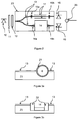
Figures 3a and 3b show cross-sections through a measurement interferometer In the optical microphone ofFigure 2 ; -
Figure 4 shows a cross-section through a layer structure by which such an optical microphone can be made; and -
Figure 5 shows the transmission function of an interferometer. -
Figure 1 shows alaser source 1, for example a laser diode, which emits light that passes through anoptical isolator 2 to a reference Fabry-Perot interferometer oretalon 3. The reference Fabry-Perot etalon 3 acts as a frequency discriminator. It can either be a solid etalon or an evacuated etalon or an air-spaced etalon isolated from the surrounding environment. -
Tuning electrodes 4 are disposed adjacent the reference Fabry-Perot etalon 3 and are used to influence its transmission characteristics in a way that a favourable operating point is established. This operating point usually is the inflexion point of the transmission function of the reference Fabry-Perot etalon 3. Theseelectrodes 4 influence the transmission characteristics by way of an electro-optic or thermo-optical effect. Alternatively, thin film resistors or Peltier elements can be used in place of thetuning electrodes 4. These make use of a thermal or thermo-optical effect to change the transmission characteristics of the reference Fabry-Perot etalon 3 thermally. - Another way to change the transmission characteristics of the reference Fabry-
Perot etalon 3 makes use of aliquid crystal 5. This element may be placed either inside or outside the reference Fabry-Perot etalon 3. - The
tuning electrodes 4 may also be replaced by a piezo-electric element deformable by electric current, which will in turn deform the reference Fabry-Perot etalon 3. Similarly, theliquid crystal 5, if used, may be replaced by an electrically-deformable lens. However, In some applications (such as an optical microphone) it is best to refrain from using mechanically deformable elements. - To prevent the
laser source 1 from being effected by optical feedback, anoptical isolator 2 is used between thelaser source 1 and the reference Fabry-Perot etalon 3. Thisisolator 2 is a combination of a linear polarising filter and a quarter wave plate. The emerging light from the reference Fabry-Perot etalon 3 is detected by aphotodetector 6, for example a PIN diode. - The light from the
laser source 1 is also incident on a measurement Fabry-Perot etalon 7, which is influenced by changes in a physical parameter (for example, air pressure). The exact manner in which the measurement Fabry-Perot etalon 7 is caused to interact with the environment so as to be influenced by the physical parameter will depend on the nature of the physical parameter. In the case of air pressure, the measurement Fabry-Perot etalon 7 will simply have a cavity that is coupled to the air through an aperture. This will become clearer below. The emerging light from the measurement Fabry-Perot etalon 7 is also detected by a photodetector (not shown), for example a PIN diode. The output signal from this photodetector will depend on the fluctuations In the physical parameter to be measured and on noise from thelaser source 1. A difference signal between the output signal from this photodetector and the output signal fromphotodetector 6 is generated by adifference amplifier 8. By this means, common mode laser noise fromlaser source 1 is cancelled. In order to dynamically adjust the DC levels from both the reference path (i.e. through reference Fabry-Perot etalon 3 and photodetector 6) and the measurement path (i.e. through measurement Fabry-Perot etalon 7 and its photodetector), thedifference amplifier 8 has a preceding gain stage where both output signals are dynamically adjusted with a long time constant. - The light from
laser source 1 may be caused to impinge on bothetalons tuning electrodes 4 andliquid crystal 5 are omitted. Thelaser source 1 is operated in pulses, alternating between the measurement path and the reference path such that successive pulses are incident on one or the other (but not both) of the reference and measurement Fabry-Perot etalons laser source 1 power supply. Even if the transmission peaks of the measurement Fabry-Perot etalon 7 do not correspond to the transmission peaks of the reference Fabry-Perot etalon 3, the ideal operating point for bothetalons laser source 1 current is adjusted for oneetalon laser source 1 current is adjusted for theother etalon - Noise cancellation is still carried out by
difference amplifier 8 after detection by the photodetectors. The switching mode is less effective for laser noise cancellation than the continuous mode using thetuning electrodes 4 orliquid crystal 5. However, computer simulation has shown that 1/f noise can be successfully cancelled nevertheless. It does have the advantage of allowing a more compact device to be constructed (due to the omission of tuningelectrodes 4 and liquid crystal 5) and having a lower overall power consumption. - As can be seen, this embodiment works by generating a noise signal (representing the noise from laser source 1) using a reference Fabry-
Perot etalon 3 and subtracting this noise signal from the signal generated using a measurement Fabry-Perot etalon 7 to improve the measurement Fabry-Perot etalon's 7 SNR. Bothetalons etalons laser source 1 are prevented from impairing the performance of the device, and it Is possible to reach the quantum or shot noise limid, even whenlaser source 1 is an unstabllised laser diode. -
Figure 2 shows an optical microphone based on the same principle as the embodiment ofFigure 1 . The optical microphone ofFigure 2 has the significant advantage that it can be manufactured without any moving parts, such as a membrane typically required in conventional miniature microphones. It therefore has a compact size and is very robust. - Furthermore, the influence of the
tuning elements 8 is intensified because of the small distance between them. For instance, the tuning mechanism may be proportional to the electric field which, in turn, is proportional to the distance between theelectrodes 8. - Laser light emitted from a laser source 10 (e.g. a PIN diode) is incident on an optical isolator consisting of a
linear polarising filter 11 and aquarter wavelength plate 12. Thereafter, the light is coupled into awaveguide structure 13. which splits the light so that it is transmitted along a measurement path, whose main element is a measurement Fabry-Perot etalon 14. and a reference path, whose main element is a reference Fabry-Perot etalon formed by twomirrors -
Tapered waveguide structures waveguide structure 13 into the measurement Fabry-Perot etalon 14. These ensure efficient coupling into the measurement Fabry-Perot etalon 14. The tapering reduces the divergence of the light emerging from thewaveguide structure 13. The reduction of divergence occurs In the dimension parallel to the plane of thesubstrate 23, typically Lithium Niobate, on which the optical microphone is built. - The reference cavity can be tuned by tuning
electrodes 17 or thin film resistors in the same manner as described with the embodiment ofFigure 1 . Light emitted from the reference andmeasurement 14 Fabry-Perot etalons is incident onrespective photodetectors 1 B, 19 and the difference signal is obtained by adifference amplifier 20. - The measurement Fabry-
Perot etalon 14 can be realised in two different ways shown inFigures 3a and 3b . InFigure 3a , a concentric mirror structure 21 (for example, either a tube or a hollow core fibre) is used. InFigure 3b , a plane parallel etalon is made by opposed parallel plane mirrors 22. - The
laser source 10 can be operated in a pulsed switching mode as with the embodiment ofFigure 1 . Two different switching modes, based on two duty cycles of different lengths, are envisaged, allowing for high SNR and low SNR operation. In the low SNR operational mode, the current consumption is greatly reduced as the duty cycle is lower. - It is possible to manufacture the optical microphone of
Figure 2 using silicon on insulator (SOI) techniques. A major advantage of thewaveguide structure 13 is the possibility to integrate the reference path so that it has small physical dimensions; the reference Fabry-Perot etalon may have dimensions of typically 1 µm to 1 mm (length) and 1 µm (width). - In order to act as a microphone, the measurement Fabry-
Perot etalon 14 Is acoustically coupled to the environment (e.g. air). This is done by making a hole in the measurement Fabry-Perot etalon 14, which provides fluid communication between an air-filled cavity in the measurement Fabry-Perot etalon 14 with the surrounding air. Thus, variations in air pressure (such as caused by an acoustic wave) are coupled to the air-filled cavity and influence the refractive index within the cavity, which is detected as a variation in light intensity atphotodetector 19. - One possible way of making an optical microphone similar to that of
Figure 2 (although without the waveguide structure) is illustrated inFigure 4 . This is a stacked or layer structure design, in which several thin optical layers and elements are stacked in contact with each other. Consequently, a compact and robust sensor is obtained. In order to omit the waveguide beam splitter used inFigure 2 , a laser diode with double-sided emission 30 embedded in asubstrate 31 is employed. Thislaser diode 30 can be a vertical cavity surface- emitting laser (VCSEL). The VCSEL can either be modified by partial removal of the substrate to allow light to be emitted from both the front and the rear sides, or, a double-sided emission can be specially manufactured by omitting part of the substrate. Another device that can be used (again, either by modification or special manufacture) for double-sided emission Is a distributed feedback (DFB) laser diode. - The layers of the stack can consist of glass, polymer, silicon or other dielectric layers, depending on the wavelength of light emitted by
laser diode 30 and the desired mechanical processing properties. Also a combination of materials in the stack is possible. The layers may be combined using bonding, gluing or other technologies. One of the emerging laser beams is incident on a reference path; the other laser beam, emitted from the opposite side is incident on a measurement path. The reference path consists of the following elements (in order of transition): an optical isolatinglayer 32, collimatinglens 33 withanti-reflection coating 53,first mirror 34 of a reference Fabry-Perot etalon, aspacer element 35,second mirror 36 of reference Fabry-Perot etalon, andphotodetector 37 embedded insubstrate 38. The reference Fabry-Perot etalon is thus fabricated from first andsecond mirrors spacer element 35, which spaces the twomirror mirrors reflection coatings - The measurement path is similar in construction. It consists of the following elements (in order of transition): an optical isolating
layer 41 , collimatinglens 42 withanti-reflection coating 43,first mirror 44 of a measurement Fabry..Perot etalon, aspacer element 45,second mirror 46 of measurement Fabry-Perot etalon, andphotodetector 47 embedded insubstrate 48. The measurement Fabry-Perot etalon is thus fabricated from first andsecond mirrors spacer element 45, which spaces the twomirror mirrors anti-reflection coatings - The
spacer element 45 has an opening oraperture 51 by way of which the air incavity 52 is coupled to the environment. The pressure of the air incavity 52 is therefore influenced by pressure changes in the environment. This in turn affects the optical transmission characteristics of the measurement Fabry-Perot etalon, and variations in air pressure will be detected as variations in output signal fromphotodetector 47. Thus, the device responds to an acoustic wave and acts as a microphone. - To influence the transmission characteristic of the reference cavity,
tuning electrodes electrodes 4 described with reference to the embodiment ofFigure 1 . - The resulting layer structure results in a very compact optical microphone and the two light beams lie on the same spatial axis. Both aspects are favourable for a cost-effective, mass producible miniature device. It is therefore very suitable for mobile communications applications.
- Other variations to the disclosed embodiments can be understood and effected by those skilled in the art in practising the claimed invention, from a study of the drawings, the disclosure, and the appended claims. In the claims, the word "comprising" does not exclude other elements or steps, and the Indefinite article "a" or "an" does not exclude a plurality. A single processor or other unit may fulfil the functions of several items recited in the claims. The mere fact that certain measures are recited in mutually different dependent claims does not indicate that a combination of these measures cannot be used to advantage. Any reference signs in the claims should not be construed as limiting the scope.
Claims (15)
- A device comprising a measurement interferometer (7) and a reference (3) Interferometer, each configured to receive light from the same light source (1) and to emit light to respective detectors (6) and having a respective operating point, wherein the measurement interferometer (7) is configured to respond to variations in a physical parameter by varying the intensity of light emitted, whereas the reference interferometer (3) is configured to be unresponsive to variations in the physical parameter, the device further comprising a signal processor for generating a difference output signal depending on respective output signals generated by the detectors (6).
- A device according to claim 1, wherein the signal processor comprises a difference amplifier (8) and a preceding gain stage for dynamical adjustment of the DC levels of the respective output signals generated by the detectors (6).
- A device according to claim 1 or 2, wherein the measurement (7) and/or reference (3) interferometers are Fabry-Perot interferometers, each preferably using mechanically rigid and/or immovable elements.
- A device according to claim 3, wherein the measurement (7) and/or reference (3) interferometers comprise a pair of spaced apart mirrors, preferably mechanically rigid and/or immovable mirrors.
- A device according to any of the preceding claims, further comprising a thermal tuning element for tuning the operating point of either the measurement (7) or the reference (3) interferometer.
- A device according to any of the preceding claims, further comprising a tuning electrode (4) for tuning the operating point of either the measurement (7) or the reference (3) interferometer.
- A device according to any of the preceding claims, further comprising a liquid crystal tuning element (6) disposed between either the measurement (7) or the reference interferometer (3) and its respective detector (6).
- A device according to any of the preceding claims, further comprising a light source controller adapted to cause the light source (1) to emit light alternately at first and second wavelengths, the operating points of the measurement (7) and reference (3) interferometers being achieved at the first and second wavelengths respectively.
- A device according to any of the preceding claims, further comprising an optical isolator (2) disposed between the light source (1) and the reference interferometer (3), the optical isolator (2) comprising a linear polariser and a quarter-wavelength plate.
- A device according to any of the preceding claims, wherein the light source (1) is a laser.
- A device according to claim 10, wherein the laser is a double-emitting laser, first and second emitted beams being coupled to the measurement (7) and reference (3) interferometers respectively.
- A device according to claim 11, wherein the double-emitting laser is a double-sided emission laser diode arranged on a substrate between first and second layer structures, each forming one of the measurement (7) and reference (3) interferometers and each comprising two respective mirror layers, preferably mechanically rigid and/or immovable mirror layers, spaced apart by respective spacer layers and detector layers distal from the substrate relative to the mirror layers.
- A device according to any of the preceding claims, wherein the signal processor further comprises an adaptive equaliser to equalise the average amplitude of the respective output generated by the detectors (6) over an equalisation time period.
- An optical microphone comprising a device according to any of the preceding claims, wherein the measurement interferometer (7) is acoustically coupled with the environment, the reference interferometer (3) is acoustically isolated from the environment, and the physical parameter is air pressure.
- An optical microphone according to claim 14, wherein the measurement interferometer (7) is acoustically coupled with its environment by an aperture in a cavity of the measurement interferometer (7).
Priority Applications (1)
| Application Number | Priority Date | Filing Date | Title |
|---|---|---|---|
| EP12722142.2A EP2710335B8 (en) | 2011-05-16 | 2012-05-16 | Optical sensor |
Applications Claiming Priority (3)
| Application Number | Priority Date | Filing Date | Title |
|---|---|---|---|
| EP11166253A EP2525194A1 (en) | 2011-05-16 | 2011-05-16 | Optical sensor |
| EP12722142.2A EP2710335B8 (en) | 2011-05-16 | 2012-05-16 | Optical sensor |
| PCT/EP2012/059122 WO2012163681A1 (en) | 2011-05-16 | 2012-05-16 | Optical sensor |
Publications (3)
| Publication Number | Publication Date |
|---|---|
| EP2710335A1 EP2710335A1 (en) | 2014-03-26 |
| EP2710335B1 true EP2710335B1 (en) | 2016-07-13 |
| EP2710335B8 EP2710335B8 (en) | 2016-09-14 |
Family
ID=44588345
Family Applications (2)
| Application Number | Title | Priority Date | Filing Date |
|---|---|---|---|
| EP11166253A Withdrawn EP2525194A1 (en) | 2011-05-16 | 2011-05-16 | Optical sensor |
| EP12722142.2A Active EP2710335B8 (en) | 2011-05-16 | 2012-05-16 | Optical sensor |
Family Applications Before (1)
| Application Number | Title | Priority Date | Filing Date |
|---|---|---|---|
| EP11166253A Withdrawn EP2525194A1 (en) | 2011-05-16 | 2011-05-16 | Optical sensor |
Country Status (6)
| Country | Link |
|---|---|
| US (1) | US9417147B2 (en) |
| EP (2) | EP2525194A1 (en) |
| JP (1) | JP6120336B2 (en) |
| KR (1) | KR101926894B1 (en) |
| CN (1) | CN103562684B (en) |
| WO (1) | WO2012163681A1 (en) |
Cited By (1)
| Publication number | Priority date | Publication date | Assignee | Title |
|---|---|---|---|---|
| DE102017205586A1 (en) | 2017-04-03 | 2018-10-04 | Robert Bosch Gmbh | Punch riveting apparatus and method for monitoring a punch riveting apparatus |
Families Citing this family (18)
| Publication number | Priority date | Publication date | Assignee | Title |
|---|---|---|---|---|
| EP3173781B8 (en) | 2015-11-25 | 2024-06-12 | Xarion Laser Acoustics GmbH | Airborne ultrasound testing system for a test object |
| US10352911B2 (en) * | 2008-09-12 | 2019-07-16 | Balthasar Fischer | Airborne ultrasound testing system for a test object |
| EP2525194A1 (en) * | 2011-05-16 | 2012-11-21 | Knowles Electronics Asia PTE. Ltd. | Optical sensor |
| CN103809281B (en) * | 2014-02-18 | 2016-05-11 | 苏州旭创科技有限公司 | Optical standard tool and assemble method thereof |
| US9874518B2 (en) | 2014-04-22 | 2018-01-23 | Sharp Kabushiki Kaisha | Optical sensor system, optical gas sensor system, particulate sensor system, light emitting apparatus, and image printing apparatus |
| US10281391B2 (en) * | 2015-06-05 | 2019-05-07 | Luminit Llc | Spectrally pure short-pulse laser |
| NO343314B1 (en) * | 2015-11-29 | 2019-01-28 | Tunable As | Optical pressure sensor |
| KR101979815B1 (en) * | 2017-08-24 | 2019-05-23 | 송광섭 | Optical Sensor |
| EP3677907A1 (en) * | 2019-01-04 | 2020-07-08 | Xarion Laser Acoustics GmbH | Device and method for testing a test object |
| CN109827653A (en) * | 2019-02-28 | 2019-05-31 | 曲阜师范大学 | A kind of complete optical fiber vector microphone probe |
| EP3734267A1 (en) | 2019-05-01 | 2020-11-04 | Northrop Grumman Innovation Systems, Inc. | Inspection devices with laser emitters and optical microphones, and related systems and methods |
| DE102019130696B4 (en) * | 2019-11-14 | 2022-07-07 | Carl Zeiss Smt Gmbh | Device for measuring a substrate and method for correcting cyclic error components of an interferometer |
| EP3825678B1 (en) * | 2019-11-22 | 2026-03-11 | Ams Ag | Apparatus and method for detecting objects |
| CN114868404A (en) * | 2020-02-25 | 2022-08-05 | 松下电器(美国)知识产权公司 | Optical microphone |
| DE102020112495B4 (en) | 2020-05-08 | 2026-04-16 | Jenoptik Automatisierungstechnik Gmbh | Method for testing an airbag cover with a predetermined breaking line and defined tear resistance |
| DE102020112494A1 (en) | 2020-05-08 | 2021-11-11 | Jenoptik Automatisierungstechnik Gmbh | Process for the production of an airbag cover with a predetermined breaking line with a defined tear resistance |
| CN114812627B (en) * | 2021-01-18 | 2025-03-21 | Tdk株式会社 | Light detecting element, receiving device and light sensor device |
| CN114414529B (en) * | 2021-12-07 | 2023-09-19 | 广东科学技术职业学院 | Salinity detection method, computer device and computer-readable storage medium |
Citations (1)
| Publication number | Priority date | Publication date | Assignee | Title |
|---|---|---|---|---|
| FR2765964A1 (en) * | 1997-07-08 | 1999-01-15 | Bertin & Cie | Optical distance measuring system using precision interferometers |
Family Cites Families (19)
| Publication number | Priority date | Publication date | Assignee | Title |
|---|---|---|---|---|
| WO1979000506A1 (en) * | 1978-01-13 | 1979-08-09 | Nat Res Dev | Interferometer systems |
| JPH03146803A (en) * | 1989-11-02 | 1991-06-21 | Kowa Co | Method and instrument for measuring distance |
| GB2314617B (en) * | 1996-06-24 | 2000-08-23 | Graviner Ltd Kidde | High sensitivity gas detection |
| JPH1163914A (en) * | 1997-08-15 | 1999-03-05 | Nikon Corp | Optical frequency domain reflected light distribution measuring device |
| US7224464B2 (en) * | 1998-11-04 | 2007-05-29 | Manning Christopher J | Fourier-transform spectrometers |
| CN100465595C (en) * | 2000-04-24 | 2009-03-04 | 周晟 | Phase difference measuring device and heterodyne interference measuring system using same |
| JP3605010B2 (en) * | 2000-08-08 | 2004-12-22 | 株式会社ミツトヨ | Surface texture measuring instrument |
| US7224465B2 (en) * | 2002-10-15 | 2007-05-29 | University Of Maryland | Fiber tip based sensor system for measurements of pressure gradient, air particle velocity and acoustic intensity |
| WO2007087040A2 (en) * | 2006-01-13 | 2007-08-02 | Luna Innovations Incorporated | Demodulation method and apparatus for fiber optic sensors |
| US7583390B2 (en) * | 2006-03-02 | 2009-09-01 | Symphony Acoustics, Inc. | Accelerometer comprising an optically resonant cavity |
| US7355723B2 (en) * | 2006-03-02 | 2008-04-08 | Symphony Acoustics, Inc. | Apparatus comprising a high-signal-to-noise displacement sensor and method therefore |
| ES3007239T3 (en) * | 2007-01-10 | 2025-03-19 | Lightlab Imaging Inc | Methods and apparatus for swept-source optical coherence tomography |
| US8007609B2 (en) * | 2007-10-31 | 2011-08-30 | Symphony Acoustics, Inc. | Parallel plate arrangement and method of formation |
| WO2009061367A2 (en) * | 2007-11-05 | 2009-05-14 | Biosensor, Inc. | Optical sensor for determining the concentration of an analyte |
| JP2009231316A (en) * | 2008-03-19 | 2009-10-08 | Nec Corp | Ld module |
| JP5667980B2 (en) * | 2008-09-12 | 2015-02-12 | ノールズ エレクトロニクス アジア ピーティーイー リミテッド | Converter system |
| GB0900705D0 (en) * | 2009-01-16 | 2009-03-04 | Univ Huddersfield | Surface measurement system |
| CN101718520B (en) * | 2009-11-16 | 2011-01-05 | 浙江大学 | A Rapid Surface Quality Measurement System |
| EP2525194A1 (en) * | 2011-05-16 | 2012-11-21 | Knowles Electronics Asia PTE. Ltd. | Optical sensor |
-
2011
- 2011-05-16 EP EP11166253A patent/EP2525194A1/en not_active Withdrawn
-
2012
- 2012-05-16 KR KR1020137030900A patent/KR101926894B1/en active Active
- 2012-05-16 EP EP12722142.2A patent/EP2710335B8/en active Active
- 2012-05-16 JP JP2014510796A patent/JP6120336B2/en active Active
- 2012-05-16 CN CN201280022889.2A patent/CN103562684B/en active Active
- 2012-05-16 WO PCT/EP2012/059122 patent/WO2012163681A1/en not_active Ceased
- 2012-05-16 US US14/117,445 patent/US9417147B2/en active Active
Patent Citations (1)
| Publication number | Priority date | Publication date | Assignee | Title |
|---|---|---|---|---|
| FR2765964A1 (en) * | 1997-07-08 | 1999-01-15 | Bertin & Cie | Optical distance measuring system using precision interferometers |
Cited By (1)
| Publication number | Priority date | Publication date | Assignee | Title |
|---|---|---|---|---|
| DE102017205586A1 (en) | 2017-04-03 | 2018-10-04 | Robert Bosch Gmbh | Punch riveting apparatus and method for monitoring a punch riveting apparatus |
Also Published As
| Publication number | Publication date |
|---|---|
| CN103562684B (en) | 2016-10-12 |
| KR101926894B1 (en) | 2018-12-07 |
| US9417147B2 (en) | 2016-08-16 |
| KR20140040720A (en) | 2014-04-03 |
| EP2525194A1 (en) | 2012-11-21 |
| WO2012163681A1 (en) | 2012-12-06 |
| EP2710335B8 (en) | 2016-09-14 |
| CN103562684A (en) | 2014-02-05 |
| US20150139451A1 (en) | 2015-05-21 |
| JP2014515114A (en) | 2014-06-26 |
| EP2710335A1 (en) | 2014-03-26 |
| JP6120336B2 (en) | 2017-04-26 |
Similar Documents
| Publication | Publication Date | Title |
|---|---|---|
| US9417147B2 (en) | Optical sensor | |
| US7359067B2 (en) | Optical displacement sensor comprising a wavelength-tunable optical source | |
| US8369367B1 (en) | Tunable laser system | |
| US6594022B1 (en) | Wavelength reference device | |
| US20140153930A1 (en) | Transducer system | |
| US20060159135A1 (en) | Narrow linewidth semiconductor laser device | |
| WO2003003082A1 (en) | Optical displacement sensor | |
| JP2002006238A (en) | Hollow structure for Fabry-Perot resonator | |
| EP3223540B1 (en) | Optical microphone system | |
| JP2012502456A (en) | Wavelength adjustable light source | |
| WO2007143362A2 (en) | Improved displacement sensor | |
| CN113206445A (en) | Tunable laser assembly | |
| CA2665527A1 (en) | Method and device for reducing laser phase noise | |
| US6665076B1 (en) | Wavelength reference device | |
| US6580516B1 (en) | Tunable Fabry Perot microelectromechanical resonator adapted for optical filters and lasers with reduced optical power-dependent tuning | |
| JP2021158267A (en) | Laser device | |
| EP2389014A1 (en) | Microphone | |
| KR101979815B1 (en) | Optical Sensor | |
| JP2016143716A (en) | Wavelength control monitor, optical module, and wavelength monitoring method | |
| Fischer et al. | Sound recording by laser interferometry |
Legal Events
| Date | Code | Title | Description |
|---|---|---|---|
| PUAI | Public reference made under article 153(3) epc to a published international application that has entered the european phase |
Free format text: ORIGINAL CODE: 0009012 |
|
| 17P | Request for examination filed |
Effective date: 20131216 |
|
| AK | Designated contracting states |
Kind code of ref document: A1 Designated state(s): AL AT BE BG CH CY CZ DE DK EE ES FI FR GB GR HR HU IE IS IT LI LT LU LV MC MK MT NL NO PL PT RO RS SE SI SK SM TR |
|
| DAX | Request for extension of the european patent (deleted) | ||
| 17Q | First examination report despatched |
Effective date: 20150701 |
|
| GRAP | Despatch of communication of intention to grant a patent |
Free format text: ORIGINAL CODE: EPIDOSNIGR1 |
|
| RIC1 | Information provided on ipc code assigned before grant |
Ipc: H04R 23/00 20060101ALI20160205BHEP Ipc: G01B 9/02 20060101ALI20160205BHEP Ipc: G01D 5/26 20060101AFI20160205BHEP Ipc: G02F 1/21 20060101ALI20160205BHEP Ipc: G01L 11/02 20060101ALI20160205BHEP |
|
| INTG | Intention to grant announced |
Effective date: 20160224 |
|
| GRAS | Grant fee paid |
Free format text: ORIGINAL CODE: EPIDOSNIGR3 |
|
| GRAA | (expected) grant |
Free format text: ORIGINAL CODE: 0009210 |
|
| AK | Designated contracting states |
Kind code of ref document: B1 Designated state(s): AL AT BE BG CH CY CZ DE DK EE ES FI FR GB GR HR HU IE IS IT LI LT LU LV MC MK MT NL NO PL PT RO RS SE SI SK SM TR |
|
| REG | Reference to a national code |
Ref country code: GB Ref legal event code: FG4D |
|
| REG | Reference to a national code |
Ref country code: AT Ref legal event code: REF Ref document number: 812712 Country of ref document: AT Kind code of ref document: T Effective date: 20160715 Ref country code: CH Ref legal event code: EP |
|
| RAP2 | Party data changed (patent owner data changed or rights of a patent transferred) |
Owner name: XARION LASER ACOUSTICS GMBH |
|
| REG | Reference to a national code |
Ref country code: IE Ref legal event code: FG4D |
|
| REG | Reference to a national code |
Ref country code: DE Ref legal event code: R096 Ref document number: 602012020426 Country of ref document: DE |
|
| REG | Reference to a national code |
Ref country code: CH Ref legal event code: NV Representative=s name: ROSENICH PAUL; KUENSCH JOACHIM PATENTBUERO PAU, LI |
|
| REG | Reference to a national code |
Ref country code: LT Ref legal event code: MG4D |
|
| REG | Reference to a national code |
Ref country code: NL Ref legal event code: MP Effective date: 20160713 |
|
| PG25 | Lapsed in a contracting state [announced via postgrant information from national office to epo] |
Ref country code: HR Free format text: LAPSE BECAUSE OF FAILURE TO SUBMIT A TRANSLATION OF THE DESCRIPTION OR TO PAY THE FEE WITHIN THE PRESCRIBED TIME-LIMIT Effective date: 20160713 Ref country code: NL Free format text: LAPSE BECAUSE OF FAILURE TO SUBMIT A TRANSLATION OF THE DESCRIPTION OR TO PAY THE FEE WITHIN THE PRESCRIBED TIME-LIMIT Effective date: 20160713 Ref country code: IT Free format text: LAPSE BECAUSE OF FAILURE TO SUBMIT A TRANSLATION OF THE DESCRIPTION OR TO PAY THE FEE WITHIN THE PRESCRIBED TIME-LIMIT Effective date: 20160713 Ref country code: FI Free format text: LAPSE BECAUSE OF FAILURE TO SUBMIT A TRANSLATION OF THE DESCRIPTION OR TO PAY THE FEE WITHIN THE PRESCRIBED TIME-LIMIT Effective date: 20160713 Ref country code: LT Free format text: LAPSE BECAUSE OF FAILURE TO SUBMIT A TRANSLATION OF THE DESCRIPTION OR TO PAY THE FEE WITHIN THE PRESCRIBED TIME-LIMIT Effective date: 20160713 Ref country code: NO Free format text: LAPSE BECAUSE OF FAILURE TO SUBMIT A TRANSLATION OF THE DESCRIPTION OR TO PAY THE FEE WITHIN THE PRESCRIBED TIME-LIMIT Effective date: 20161013 Ref country code: RS Free format text: LAPSE BECAUSE OF FAILURE TO SUBMIT A TRANSLATION OF THE DESCRIPTION OR TO PAY THE FEE WITHIN THE PRESCRIBED TIME-LIMIT Effective date: 20160713 Ref country code: IS Free format text: LAPSE BECAUSE OF FAILURE TO SUBMIT A TRANSLATION OF THE DESCRIPTION OR TO PAY THE FEE WITHIN THE PRESCRIBED TIME-LIMIT Effective date: 20161113 |
|
| PG25 | Lapsed in a contracting state [announced via postgrant information from national office to epo] |
Ref country code: ES Free format text: LAPSE BECAUSE OF FAILURE TO SUBMIT A TRANSLATION OF THE DESCRIPTION OR TO PAY THE FEE WITHIN THE PRESCRIBED TIME-LIMIT Effective date: 20160713 Ref country code: GR Free format text: LAPSE BECAUSE OF FAILURE TO SUBMIT A TRANSLATION OF THE DESCRIPTION OR TO PAY THE FEE WITHIN THE PRESCRIBED TIME-LIMIT Effective date: 20161014 Ref country code: SE Free format text: LAPSE BECAUSE OF FAILURE TO SUBMIT A TRANSLATION OF THE DESCRIPTION OR TO PAY THE FEE WITHIN THE PRESCRIBED TIME-LIMIT Effective date: 20160713 Ref country code: PT Free format text: LAPSE BECAUSE OF FAILURE TO SUBMIT A TRANSLATION OF THE DESCRIPTION OR TO PAY THE FEE WITHIN THE PRESCRIBED TIME-LIMIT Effective date: 20161114 Ref country code: PL Free format text: LAPSE BECAUSE OF FAILURE TO SUBMIT A TRANSLATION OF THE DESCRIPTION OR TO PAY THE FEE WITHIN THE PRESCRIBED TIME-LIMIT Effective date: 20160713 Ref country code: BE Free format text: LAPSE BECAUSE OF FAILURE TO SUBMIT A TRANSLATION OF THE DESCRIPTION OR TO PAY THE FEE WITHIN THE PRESCRIBED TIME-LIMIT Effective date: 20160713 Ref country code: LV Free format text: LAPSE BECAUSE OF FAILURE TO SUBMIT A TRANSLATION OF THE DESCRIPTION OR TO PAY THE FEE WITHIN THE PRESCRIBED TIME-LIMIT Effective date: 20160713 |
|
| REG | Reference to a national code |
Ref country code: DE Ref legal event code: R097 Ref document number: 602012020426 Country of ref document: DE |
|
| PG25 | Lapsed in a contracting state [announced via postgrant information from national office to epo] |
Ref country code: EE Free format text: LAPSE BECAUSE OF FAILURE TO SUBMIT A TRANSLATION OF THE DESCRIPTION OR TO PAY THE FEE WITHIN THE PRESCRIBED TIME-LIMIT Effective date: 20160713 Ref country code: RO Free format text: LAPSE BECAUSE OF FAILURE TO SUBMIT A TRANSLATION OF THE DESCRIPTION OR TO PAY THE FEE WITHIN THE PRESCRIBED TIME-LIMIT Effective date: 20160713 |
|
| PLBE | No opposition filed within time limit |
Free format text: ORIGINAL CODE: 0009261 |
|
| STAA | Information on the status of an ep patent application or granted ep patent |
Free format text: STATUS: NO OPPOSITION FILED WITHIN TIME LIMIT |
|
| PG25 | Lapsed in a contracting state [announced via postgrant information from national office to epo] |
Ref country code: CZ Free format text: LAPSE BECAUSE OF FAILURE TO SUBMIT A TRANSLATION OF THE DESCRIPTION OR TO PAY THE FEE WITHIN THE PRESCRIBED TIME-LIMIT Effective date: 20160713 Ref country code: SM Free format text: LAPSE BECAUSE OF FAILURE TO SUBMIT A TRANSLATION OF THE DESCRIPTION OR TO PAY THE FEE WITHIN THE PRESCRIBED TIME-LIMIT Effective date: 20160713 Ref country code: DK Free format text: LAPSE BECAUSE OF FAILURE TO SUBMIT A TRANSLATION OF THE DESCRIPTION OR TO PAY THE FEE WITHIN THE PRESCRIBED TIME-LIMIT Effective date: 20160713 Ref country code: BG Free format text: LAPSE BECAUSE OF FAILURE TO SUBMIT A TRANSLATION OF THE DESCRIPTION OR TO PAY THE FEE WITHIN THE PRESCRIBED TIME-LIMIT Effective date: 20161013 Ref country code: SK Free format text: LAPSE BECAUSE OF FAILURE TO SUBMIT A TRANSLATION OF THE DESCRIPTION OR TO PAY THE FEE WITHIN THE PRESCRIBED TIME-LIMIT Effective date: 20160713 |
|
| 26N | No opposition filed |
Effective date: 20170418 |
|
| PG25 | Lapsed in a contracting state [announced via postgrant information from national office to epo] |
Ref country code: SI Free format text: LAPSE BECAUSE OF FAILURE TO SUBMIT A TRANSLATION OF THE DESCRIPTION OR TO PAY THE FEE WITHIN THE PRESCRIBED TIME-LIMIT Effective date: 20160713 Ref country code: LU Free format text: LAPSE BECAUSE OF NON-PAYMENT OF DUE FEES Effective date: 20170531 |
|
| PG25 | Lapsed in a contracting state [announced via postgrant information from national office to epo] |
Ref country code: MC Free format text: LAPSE BECAUSE OF FAILURE TO SUBMIT A TRANSLATION OF THE DESCRIPTION OR TO PAY THE FEE WITHIN THE PRESCRIBED TIME-LIMIT Effective date: 20160713 |
|
| REG | Reference to a national code |
Ref country code: IE Ref legal event code: MM4A |
|
| REG | Reference to a national code |
Ref country code: FR Ref legal event code: ST Effective date: 20180131 |
|
| PG25 | Lapsed in a contracting state [announced via postgrant information from national office to epo] |
Ref country code: LU Free format text: LAPSE BECAUSE OF NON-PAYMENT OF DUE FEES Effective date: 20170516 |
|
| PG25 | Lapsed in a contracting state [announced via postgrant information from national office to epo] |
Ref country code: IE Free format text: LAPSE BECAUSE OF NON-PAYMENT OF DUE FEES Effective date: 20170516 |
|
| PG25 | Lapsed in a contracting state [announced via postgrant information from national office to epo] |
Ref country code: FR Free format text: LAPSE BECAUSE OF NON-PAYMENT OF DUE FEES Effective date: 20170531 |
|
| PG25 | Lapsed in a contracting state [announced via postgrant information from national office to epo] |
Ref country code: MT Free format text: LAPSE BECAUSE OF NON-PAYMENT OF DUE FEES Effective date: 20170516 |
|
| PG25 | Lapsed in a contracting state [announced via postgrant information from national office to epo] |
Ref country code: AL Free format text: LAPSE BECAUSE OF FAILURE TO SUBMIT A TRANSLATION OF THE DESCRIPTION OR TO PAY THE FEE WITHIN THE PRESCRIBED TIME-LIMIT Effective date: 20160713 |
|
| PG25 | Lapsed in a contracting state [announced via postgrant information from national office to epo] |
Ref country code: HU Free format text: LAPSE BECAUSE OF FAILURE TO SUBMIT A TRANSLATION OF THE DESCRIPTION OR TO PAY THE FEE WITHIN THE PRESCRIBED TIME-LIMIT; INVALID AB INITIO Effective date: 20120516 |
|
| PG25 | Lapsed in a contracting state [announced via postgrant information from national office to epo] |
Ref country code: CY Free format text: LAPSE BECAUSE OF NON-PAYMENT OF DUE FEES Effective date: 20160713 |
|
| PG25 | Lapsed in a contracting state [announced via postgrant information from national office to epo] |
Ref country code: MK Free format text: LAPSE BECAUSE OF FAILURE TO SUBMIT A TRANSLATION OF THE DESCRIPTION OR TO PAY THE FEE WITHIN THE PRESCRIBED TIME-LIMIT Effective date: 20160713 |
|
| PG25 | Lapsed in a contracting state [announced via postgrant information from national office to epo] |
Ref country code: TR Free format text: LAPSE BECAUSE OF FAILURE TO SUBMIT A TRANSLATION OF THE DESCRIPTION OR TO PAY THE FEE WITHIN THE PRESCRIBED TIME-LIMIT Effective date: 20160713 |
|
| REG | Reference to a national code |
Ref country code: AT Ref legal event code: UEP Ref document number: 812712 Country of ref document: AT Kind code of ref document: T Effective date: 20160713 |
|
| REG | Reference to a national code |
Ref country code: CH Ref legal event code: PCAR Free format text: NEW ADDRESS: ROTENBODENSTRASSE 12, 9497 TRIESENBERG (LI) |
|
| REG | Reference to a national code |
Ref country code: DE Ref legal event code: R082 Ref document number: 602012020426 Country of ref document: DE Representative=s name: VOSSIUS & PARTNER PATENTANWAELTE RECHTSANWAELT, DE Ref country code: DE Ref legal event code: R082 Ref document number: 602012020426 Country of ref document: DE Representative=s name: NEUHOLD, ALFRED, DR.TECHN., CH Ref country code: DE Ref legal event code: R082 Ref document number: 602012020426 Country of ref document: DE Representative=s name: NEUHOLD, ALFRED, DR.TECHN., LI |
|
| P01 | Opt-out of the competence of the unified patent court (upc) registered |
Effective date: 20230515 |
|
| REG | Reference to a national code |
Ref country code: DE Ref legal event code: R082 Ref document number: 602012020426 Country of ref document: DE Representative=s name: NEUHOLD, ALFRED, DR.TECHN., CH Ref country code: DE Ref legal event code: R082 Ref document number: 602012020426 Country of ref document: DE Representative=s name: NEUHOLD, ALFRED, DR.TECHN., LI |
|
| PGFP | Annual fee paid to national office [announced via postgrant information from national office to epo] |
Ref country code: DE Payment date: 20250521 Year of fee payment: 14 |
|
| PGFP | Annual fee paid to national office [announced via postgrant information from national office to epo] |
Ref country code: GB Payment date: 20250521 Year of fee payment: 14 |
|
| PGFP | Annual fee paid to national office [announced via postgrant information from national office to epo] |
Ref country code: CH Payment date: 20250601 Year of fee payment: 14 |
|
| PGFP | Annual fee paid to national office [announced via postgrant information from national office to epo] |
Ref country code: AT Payment date: 20250522 Year of fee payment: 14 |