EP2710222B1 - Linear pressure reducer for regulating injection pressure in an enhanced oil recovery system - Google Patents
Linear pressure reducer for regulating injection pressure in an enhanced oil recovery system Download PDFInfo
- Publication number
- EP2710222B1 EP2710222B1 EP12727429.8A EP12727429A EP2710222B1 EP 2710222 B1 EP2710222 B1 EP 2710222B1 EP 12727429 A EP12727429 A EP 12727429A EP 2710222 B1 EP2710222 B1 EP 2710222B1
- Authority
- EP
- European Patent Office
- Prior art keywords
- pressure
- modules
- injection
- polymer
- tubes
- Prior art date
- Legal status (The legal status is an assumption and is not a legal conclusion. Google has not performed a legal analysis and makes no representation as to the accuracy of the status listed.)
- Active
Links
Images

Classifications
-
- E—FIXED CONSTRUCTIONS
- E21—EARTH OR ROCK DRILLING; MINING
- E21B—EARTH OR ROCK DRILLING; OBTAINING OIL, GAS, WATER, SOLUBLE OR MELTABLE MATERIALS OR A SLURRY OF MINERALS FROM WELLS
- E21B43/00—Methods or apparatus for obtaining oil, gas, water, soluble or meltable materials or a slurry of minerals from wells
- E21B43/16—Enhanced recovery methods for obtaining hydrocarbons
-
- E—FIXED CONSTRUCTIONS
- E21—EARTH OR ROCK DRILLING; MINING
- E21B—EARTH OR ROCK DRILLING; OBTAINING OIL, GAS, WATER, SOLUBLE OR MELTABLE MATERIALS OR A SLURRY OF MINERALS FROM WELLS
- E21B34/00—Valve arrangements for boreholes or wells
- E21B34/02—Valve arrangements for boreholes or wells in well heads
- E21B34/025—Chokes or valves in wellheads and sub-sea wellheads for variably regulating fluid flow
-
- E—FIXED CONSTRUCTIONS
- E21—EARTH OR ROCK DRILLING; MINING
- E21B—EARTH OR ROCK DRILLING; OBTAINING OIL, GAS, WATER, SOLUBLE OR MELTABLE MATERIALS OR A SLURRY OF MINERALS FROM WELLS
- E21B43/00—Methods or apparatus for obtaining oil, gas, water, soluble or meltable materials or a slurry of minerals from wells
- E21B43/16—Enhanced recovery methods for obtaining hydrocarbons
- E21B43/20—Displacing by water
Definitions
- the invention is a linear pressure reducer for regulating injection pressure in injection wellheads in an enhanced oil recovery system.
- Another object of the invention is an enhanced oil recovery system that implements the aforementioned linear pressure reducer.
- a pressure reducer apparatus for regulating injection in an enhanced oil recovery system is known from US 4276904 .
- primary production obtains oil by using reservoir pressure.
- reservoir pressure is maintained by injecting pressurised water.
- the feed pump is usually set to a pressure of 20 bar above the pressure of the well with the highest pressure.
- Each well contains a pressure reducing valve called a choke in its wellhead, which allows control over the injection pressure and the water flow rate into each well.
- the pressure of the wells varies according to multiple factors: reaction to the injection, the salinity of the injected solution, the effect of filtering impurities...
- the choke allows the injection pressure to be reduced to the desired pressure at any time, with a different regulator for each well.
- Loss of viscosity is then directly linked to pressure drop through the choke and the diameter of the openings.
- degradation is roughly linear up until 20 bar of pressure drop and can be compensated by increasing the concentration of the polymer. Beyond 20 bar, degradation accelerates.
- a choke with pressure drop of 40 bar reduces the viscosity of a polyacrylamide solution by an average of 50%.
- the dissolution station may be:
- a third solution that has been tested with little success is cyclic injection. With a group of wells, the solution is injected into a single well at a time, and in cycles. When the injection finishes, the pressure progressively decreases then to increase once more for the following injection cycle at a pressure inferior to the fracturing pressure. This complex and efficiency is low.
- the market is therefore lacking a device that reduces pressure, even at very high values, without degrading the polymer. More precisely, the aim is to develop a device that can regulate injection pressure with respect to the evolution of well pressure which varies, as we have already discussed, depending on multiple factors, all at high speed, with no substantial degradation of the polymer.
- the Applicant has ascertained that it is possible to reduce pressure without notably affecting the viscosity of the polymer and this when using, despite the high injection speeds, tubes with lengths greater than 100 metres, from approximately 100 to 500 metres to be specific.
- the Applicant has developed a linear pressure reducer device, composed of tubes of different lengths and giving variable pressure drops without an substantial degradation in fluid viscosity.
- the object of the invention is a linear pressure reducer that will regulate the injection pressure of a water-soluble polymer solution in the wellhead of an injection well, during enhanced oil recovery.
- the reducer device consists of modules connected in series to the main pipe, each consisting of a tube of the same diameter but with variable length, said device allowing pressure drop to be varied by adjusting the length of the tube through which the solution flows, by opening or closing modules, without substantial degradation of the solution viscosity during its passage through the module.
- tests can determine the tube diameter and length needed to obtain the desired range of pressure reduction. This length is then cut into modules, meaning the pressure can be adjusted on demand, by using all or some of the modules.
- the length of the tubes that form the modules can be 10, 20, 50, 100 or 200 metres for example.
- the diameter of the tubes that form the modules should be between 1 ⁇ 2 and 4 inches and preferably between 1 ⁇ 2 and 2 inches for standard vertical or horizontal wells.
- the diameter of the tubes is adapted to the flow of polymer for each injection well.
- the aforementioned models are equipped with by-pass valves and are preferably circular in shape to reduce blockage.
- the valves can be operated manually or remotely from a central control room.
- the metal used for the construction of the tubes must be adapted to the brine composition and temperature according to rules that are well known to specialist Petroleum Engineers.
- This construction may use stainless steel 304, stainless steel 316, duplex, super duplex, Hastelloy and in some instances copper...
- injection rates of water or polymer solution are between 4 and 50 m 3 /hour in most cases.
- pumping tests determine the range of pressure and the pressure drops at which the viscosity of the polymer solution has not degraded more than 10%, preferable not more than 5%.
- Another object of the invention is an enhanced oil recovery installation using polymer injection that implements the linear pressure reducer, particularly on an offshore installation.
- the device is positioned between the high pressure line feeding the wells with polymer solution and each wellhead.
- Example 1a Test on a tube with a diameter of 1 ⁇ 2" and a length of 100m
- a synthetic brine is used that corresponds to brine typically found in the Middle East with the following composition:
- Polyacrylamide 3630S (70% mole of acrylamide/30% mole of acrylic acid, 20 million g/mole) 1000 ppm Initial viscosity 17.2 cP (Brookfield UL 6 rpm, 50°C)
- the diaphragm pump is connected to a 100m long tube, with an internal diameter of 13.46 mm equipped with a pressure gauge and precision flow metre. Each test lasts three minutes at a constant flow rate.
- Example 1b Test on a 1 inch tube (internal diameter of 26.63mm, length 100mm)
- the reducer will therefore consist of modules of 10m, 20m, 50m, 100m and 200m; the combination of which will permit the following pressure drops:
- the pressure drop can be modified on line by opening or closing the valves which means that each module can be short-circuited or activated. If necessary the difference in pressure can be either reduced or increased, by adding low amplitude modules of 10 to 20 metres.
- FIG. 2 shows a linear pressure reducer according to the invention.
- This method of construction includes 5 modules identified respectively as 1 to 5 connected in series with the main injection line (6).
- Each module is equipped with a by-pass valve of 7 to 11 which allows the module to be short-circuited or not.
- the modules consist of tubes of varying length, from 10 to 200 metres. As shown in figure 3 , the tubes forming the module are in a spiral shape, which significantly reduces the size of the device. All the lengths can also be put in the same box with the valves in the front section.
- Opening or closing the modules allows the pressure drop of the injection wells to be continuously controlled without substantially altering the viscosity of the polymer solution, all at high injection speeds.
Landscapes
- Geology (AREA)
- Life Sciences & Earth Sciences (AREA)
- Engineering & Computer Science (AREA)
- Mining & Mineral Resources (AREA)
- Environmental & Geological Engineering (AREA)
- Fluid Mechanics (AREA)
- Physics & Mathematics (AREA)
- General Life Sciences & Earth Sciences (AREA)
- Geochemistry & Mineralogy (AREA)
- Addition Polymer Or Copolymer, Post-Treatments, Or Chemical Modifications (AREA)
- Excavating Of Shafts Or Tunnels (AREA)
- Physical Or Chemical Processes And Apparatus (AREA)
- Lubricants (AREA)
Description
- The invention is a linear pressure reducer for regulating injection pressure in injection wellheads in an enhanced oil recovery system. Another object of the invention is an enhanced oil recovery system that implements the aforementioned linear pressure reducer.
- A pressure reducer apparatus for regulating injection in an enhanced oil recovery system is known from
US 4276904 . In the oil extraction industry, primary production obtains oil by using reservoir pressure. - In secondary production, reservoir pressure is maintained by injecting pressurised water.
- In the 1970s, the use of enhanced oil recovery (EOR) using a polymer began, where the water injected is made viscous by the addition of water-soluble polymers so as to widen the injection bulb, increase reservoir sweep and recover more oil in position, by physical effect. The polymers used are:
- Either natural: xanthan gum, guar gum, cellulose derivatives,
- Or synthetic: polyacrylamide, polyacrylates, polyvinylpyrrolidone...
- In practice, where a single polymer injection pump is used to feed several wells at different pressures, it must simultaneously:
- pump at a determined rate so as to maintain sufficient pressure in all wells,
- reduce pressure in certain wells so as not to fracture them,
- adapt the torque pressure/rate to the selected injection plan.
- The feed pump is usually set to a pressure of 20 bar above the pressure of the well with the highest pressure.
- Each well contains a pressure reducing valve called a choke in its wellhead, which allows control over the injection pressure and the water flow rate into each well. The pressure of the wells varies according to multiple factors: reaction to the injection, the salinity of the injected solution, the effect of filtering impurities... The choke allows the injection pressure to be reduced to the desired pressure at any time, with a different regulator for each well.
- One of the main problems, in the case of enhanced oil recovery, is the mechanical degradation that the polymer undergoes due to the variation in desired pressure created by the choke, this variation corresponds in general to a pressure drop of 10-50 bar. As the polymer degrades, the chokes significantly reduce the viscosity of the solution to be injected, thus limiting oil recovery.
- Studies carried out into the mechanical degradation of polymers in solution are all empirical due to the drag, or friction, reduction effect, which has not been scientifically evaluated in a non-Newtonian system.
- The figures available for loss of pressure, flow, speed and degradation are therefore very disparate.
- It was found that degradation in the valves of piston or diaphragm pumps begins at speeds of 3 metres per second.
- In standard chokes, which either have a single opening with limited precision, or multiple openings rotary ones (Cameron) with a low diameter of holes, degradation starts very early, at differences in pressure of 5 bar while, as mentioned above, they most frequently work with a pressure drop of 10 to 50 bar, especially in offshore application (see
figure 1 ). There is therefore an adjustment flow rate with variable but significant degradation, as extremely high decompression forces cause cavitation effects that are practically explosive. - Loss of viscosity is then directly linked to pressure drop through the choke and the diameter of the openings. Typically, for a rotary choke, degradation is roughly linear up until 20 bar of pressure drop and can be compensated by increasing the concentration of the polymer. Beyond 20 bar, degradation accelerates.
For example, a choke with pressure drop of 40 bar reduces the viscosity of a polyacrylamide solution by an average of 50%. - This phenomenon becomes extremely important in offshore operations where chokes on the seabed feed several injectors with pressure reductions, sometimes exceeding 50 bar. On inshore installation this problem is usually solved by feeding each well separately from a central polymer dissolution station. In this case the polymer is dissolved at high concentrations (5 - 20 g/litre) and injected at high pressure by volumetric pump into the controlled flow of water into each well. The choke is located before the injection of the polymer, which is then protected from mechanical degradation.
- The dissolution station may be:
- centralised with a water-polymer mix made at the polymer preparation station and transported via pipeline to each well,
- it can also be distributed with two water - polymer circuits that circle the reservoir and injectors and with a choke for the water, then a localised polymer pump for the wells.
- The two solutions are virtually equivalent in terms of cost.
- A third solution that has been tested with little success is cyclic injection. With a group of wells, the solution is injected into a single well at a time, and in cycles. When the injection finishes, the pressure progressively decreases then to increase once more for the following injection cycle at a pressure inferior to the fracturing pressure. This complex and efficiency is low.
- The market is therefore lacking a device that reduces pressure, even at very high values, without degrading the polymer. More precisely, the aim is to develop a device that can regulate injection pressure with respect to the evolution of well pressure which varies, as we have already discussed, depending on multiple factors, all at high speed, with no substantial degradation of the polymer.
- Tests were conducted using tubes of short length (6 - 12 metres) and reduced section. Nonetheless, degradation of viscosity was still observed, meaning the system cannot be used commercially beyond a few bars of pressure drop.
- The Applicant has ascertained that it is possible to reduce pressure without notably affecting the viscosity of the polymer and this when using, despite the high injection speeds, tubes with lengths greater than 100 metres, from approximately 100 to 500 metres to be specific.
- Based on this finding and to solve the problem of regulating injection pressure as a function of well pressure, without substantially affecting the viscosity of the injection solution and at high injection flow rates, the Applicant has developed a linear pressure reducer device, composed of tubes of different lengths and giving variable pressure drops without an substantial degradation in fluid viscosity.
- To be more precise, the object of the invention is a linear pressure reducer that will regulate the injection pressure of a water-soluble polymer solution in the wellhead of an injection well, during enhanced oil recovery.
- The reducer device consists of modules connected in series to the main pipe, each consisting of a tube of the same diameter but with variable length, said device allowing pressure drop to be varied by adjusting the length of the tube through which the solution flows, by opening or closing modules, without substantial degradation of the solution viscosity during its passage through the module.
- In practice, when the recommended injection rate and composition of the injection solution are known, tests can determine the tube diameter and length needed to obtain the desired range of pressure reduction. This length is then cut into modules, meaning the pressure can be adjusted on demand, by using all or some of the modules.
- The length of the tubes that form the modules can be 10, 20, 50, 100 or 200 metres for example.
- In reality, the diameter of the tubes that form the modules should be between ½ and 4 inches and preferably between ½ and 2 inches for standard vertical or horizontal wells. The diameter of the tubes is adapted to the flow of polymer for each injection well.
- The aforementioned models are equipped with by-pass valves and are preferably circular in shape to reduce blockage.
- The valves can be operated manually or remotely from a central control room.
- The metal used for the construction of the tubes must be adapted to the brine composition and temperature according to rules that are well known to specialist Petroleum Engineers. This construction may use stainless steel 304, stainless steel 316, duplex, super duplex, Hastelloy and in some instances copper...
- In shore reservoirs, injection rates of water or polymer solution are between 4 and 50 m3/hour in most cases.
- The goal then is to build pressure reducers that work at between 4 and 50 m3/hour (and even beyond that) with pressure drops of 10 to 50 bar and a minimum molecular weight degradation. This data cannot be obtained via calculation; it is therefore necessary to carry out systematic tests reservoir by reservoir to check the brine injected (which has a strong influence on viscosity), the type and concentration of polymer and derived pressure reductions, the effects of the walls, the shape of the pipes or pulsations...
- More precisely, for a given tube length and diameter, pumping tests determine the range of pressure and the pressure drops at which the viscosity of the polymer solution has not degraded more than 10%, preferable not more than 5%.
- These tests are carried out for example with polymer solutions in reservoir brine with a 40 bars diaphragm metering pump equipped with pulsation absorber for a flow of 40 m3/hour through circulating coiled tubes of 100 metres, with diameters of ½, ¾, 1, 1 ¼ inches made from stainless steel. These allow us to define for a given length and diameter the range of pressure and the pressure drops at which the polymer will not be substantially degraded.
- By not substantially degraded, we intend a degradation in the Brookfield viscosity of the polymer in solution, at injection concentration, of less than 10% and preferably less than 5% compared to the original value.
- It is also possible to use hairpin tubes but the sudden change in direction can cause supplementary polymer degradation.
- An important advantage of this type of linear pressure reducer is the easy control of chokes submerged offshore, this control is limited to the opening or closing of 4 to 5 valves.
- Another object of the invention then is an enhanced oil recovery installation using polymer injection that implements the linear pressure reducer, particularly on an offshore installation.
- In practice, the device is positioned between the high pressure line feeding the wells with polymer solution and each wellhead.
- The invention and its advantages are clearly demonstrated in the following examples, which support the accompanying drawings.
-
Figure 1 is a graph showing the degradation of an acrylamide polymer (30% anionic with a molecular weight of 20 million) relative to pressure drop of a choke. -
Figure 2 is a diagram showing the sequence of modules in an enhanced oil recovery installation. -
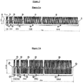
Figure 3 contains two schematic representations of modules of 380m in length with spiral diameters of 650mm (3a) and 1000mm (3b). - These preliminary tests were carried out with solutions of polymer in reservoir brine with a 40 bars diaphragm metering pump equipped with a pulsation absorber for a flow of 40m3/hour through circulating coiled tubes of 100 metres, with diameters of ½, ¾, 1, 1 ¼ inches made from stainless steel. These allow us to define for a fixed length of 100 metres and given diameter the range of pressure and the pressure drops at which the polymer will not be too degraded.
- A synthetic brine is used that corresponds to brine typically found in the Middle East with the following composition:
- Na+ 1660 ppm
- K+ 25 ppm
- Ca2+ 26 ppm
- Mg2+ 11 ppm
- Cl- 1962 ppm
- HCO3-951 ppm
- SO42 160 ppm
-
Fer2+ 0 ppm -
H2S 30 ppm - Polyacrylamide 3630S (70% mole of acrylamide/30% mole of acrylic acid, 20 million g/mole) 1000 ppm
Initial viscosity 17.2 cP (Brookfield UL 6 rpm, 50°C) - The diaphragm pump is connected to a 100m long tube, with an internal diameter of 13.46 mm equipped with a pressure gauge and precision flow metre.
Each test lasts three minutes at a constant flow rate. - The results obtained are listed below.
Flow rate m3/ h 0 2.5 4 4.5 5 Speed (m/sec) 0 4.88 7.81 8.78 9.76 Pressure drop (bar) 0 4.5 8.4 9.6 11.3 Output viscosity (cps) Brookfield UL 6 rpm17.2 16.8 16.7 16.7 15.9 Degradation (%) 2.3 2.9 2.9 7.5 - We observe that very high speeds near 10m/second can be reached, with a pressure drop of 1 bar per 10 metres, without signs of substantial degradation and with flow rates of 5m3/hour for a ½ inch pipe with an interior diameter of 13.46mm.
- Degradation of 7.5% is still very low in comparison to polymer degradation in the reservoir. However, if pressure drop is high, cumulative degradation with larger widths must be considered and the flow rate be reduced or the size of the pipe increased.
- The same brine at 50°C was used to perform these tests in the same conditions with the following results:
Flow rate m3/ h 0 19.5 31 35 38.5 Speed (m/sec) 0 9.7 15.4 17.4 19.2 Pressure drop (bar) 0 4 7.8 9.1 11.3 Output viscosity (cps) Brookfield UL 6 rpm17.0 16.9 16.7 16.6 15.4 Degradation (%) 0.60 1.76 2.35 9.41 - This demonstrates that there may be a drop of 1 bar per 10 metres with flow rates from 19 to 38 m3/h in a 1 inch tube with an internal diameter of 26.64mm.
These tests can be performed on any tube of different diameter. - On a well where the injection flow rate, with a solution identical to the one above, is 4m3/h and the desired change in pressure is from 0 to 30 bar, the pressure drop per metre will be 0.084 bar and the necessary length will be 357 metres. The reducer will therefore consist of modules of 10m, 20m, 50m, 100m and 200m; the combination of which will permit the following pressure drops:
- 10m - 0.84 bar
- 20m - 1.68 bar
- 10m + 20m - 2.52 bar
- 50m - 4.2 bar
- 50m + 10m - 5.04 bar
- 50m + 20m - 5.88 bar
- 50m + 20m + 10m - 6.72 bar
- 100m - 8.4 bar
- 100m + 10m - 9.24 bar...
- 200+100+50+20+10 - 31.92 bar
- The pressure drop can be modified on line by opening or closing the valves which means that each module can be short-circuited or activated. If necessary the difference in pressure can be either reduced or increased, by adding low amplitude modules of 10 to 20 metres.
-
Figure 2 shows a linear pressure reducer according to the invention. This method of construction includes 5 modules identified respectively as 1 to 5 connected in series with the main injection line (6). Each module is equipped with a by-pass valve of 7 to 11 which allows the module to be short-circuited or not. The modules consist of tubes of varying length, from 10 to 200 metres.
As shown infigure 3 , the tubes forming the module are in a spiral shape, which significantly reduces the size of the device. All the lengths can also be put in the same box with the valves in the front section. - Opening or closing the modules allows the pressure drop of the injection wells to be continuously controlled without substantially altering the viscosity of the polymer solution, all at high injection speeds.
Claims (8)
- Linear pressure reducer apparatus for regulating injection pressure of a water-soluble polymer solution in injection wellheads, in an enhanced oil recovery system, including modules connected to the main injection pipe and each consisting of tubes of identical diameter but variable length, the said apparatus allows variations to be made to pressure drop through adjusting the length of the tube through which the solution flows by closing or opening modules, without substantial degradation to the viscosity of the solution during its passage through the module, characterized in that the modules are connected in series to the main injection pipe.
- Apparatus according to claim 1, characterised in that for a given tube length and diameter pumping tests determine the pressure range and pressure drops at which the viscosity of the polymer solution does not degrade more than 10%.
- Apparatus according to claim 1, characterised in that for a given tube length and diameter pumping tests determine the pressure range and pressure drops at which the viscosity of the polymer solution does not degrade more than 5%.
- Apparatus according to the previous claims, characterised in that each module is equipped with a by-pass valve, the lengths of tubes that compose the modules are 10, 20, 50, 100 or 200 metres.
- Apparatus according to the previous claims, characterised in that the diameter of the tubes composing the modules are between ½ and 4 inches and preferably between ½ and 2 inches, adapted to the flow of polymer for each injection well.
- Apparatus according to claim 1, characterised in that the tubes composing the modules are built of material that is resistant to corrosion in conditions equal to the composition and temperature of brine, selected from stainless steel 304, stainless steel 316, duplex, super duplex and Hastelloy and in some instance copper.
- Installation of an enhanced oil recovery system by polymer injection using the linear pressure reducer subject of claim 1-6.
- Installation according to claim 7, characterised in that the installation is offshore.
Applications Claiming Priority (2)
| Application Number | Priority Date | Filing Date | Title |
|---|---|---|---|
| US13/112,722 US8607869B2 (en) | 2011-05-20 | 2011-05-20 | Linear pressure reducer for regulating injection pressure in an enhanced oil recovery system |
| PCT/IB2012/052311 WO2012160469A2 (en) | 2011-05-20 | 2012-05-09 | Linear pressure reducer for regulating injection pressure in an enhanced oil recovery system |
Publications (2)
| Publication Number | Publication Date |
|---|---|
| EP2710222A2 EP2710222A2 (en) | 2014-03-26 |
| EP2710222B1 true EP2710222B1 (en) | 2017-07-12 |
Family
ID=46275924
Family Applications (1)
| Application Number | Title | Priority Date | Filing Date |
|---|---|---|---|
| EP12727429.8A Active EP2710222B1 (en) | 2011-05-20 | 2012-05-09 | Linear pressure reducer for regulating injection pressure in an enhanced oil recovery system |
Country Status (6)
| Country | Link |
|---|---|
| US (1) | US8607869B2 (en) |
| EP (1) | EP2710222B1 (en) |
| CN (1) | CN104246124B (en) |
| BR (1) | BR112013027862B1 (en) |
| HU (1) | HUE033511T2 (en) |
| WO (1) | WO2012160469A2 (en) |
Families Citing this family (9)
| Publication number | Priority date | Publication date | Assignee | Title |
|---|---|---|---|---|
| BR112016016492B1 (en) | 2014-01-24 | 2022-05-17 | Cameron Technologies Limited | SYSTEMS AND METHODS FOR THE REDUCTION OF POLYMER DEGRADATION |
| FR3026773B1 (en) | 2014-10-01 | 2019-03-29 | S.P.C.M. Sa | INJECTION PRESSURE CONTROL APPARATUS IN THE ASSISTED RECOVERY OF OFFSHORE OIL |
| FR3046194B1 (en) * | 2015-12-23 | 2018-01-05 | S.P.C.M. Sa | APPARATUS FOR CONTROLLING INJECTION PRESSURE IN THE ASSISTED RECOVERY OF PETROLEUM |
| GB2554412B (en) * | 2016-09-26 | 2020-01-08 | Equinor Energy As | Method and apparatus for reducing liquid pressure |
| FR3057011B1 (en) | 2016-10-03 | 2018-11-02 | S.P.C.M. Sa | INJECTION PRESSURE REGULATING APPARATUS FOR THE ASSISTED RECOVERY OF PETROLEUM BY POLYMER |
| FR3061909B1 (en) | 2017-01-19 | 2019-05-24 | S.P.C.M. Sa | PROCESS FOR ASSISTED OIL RECOVERY BY INJECTION OF A POLYMERIC AQUEOUS COMPOSITION CONTAINING MICROGELS |
| FR3075219B1 (en) | 2017-12-14 | 2019-11-22 | S.P.C.M. Sa | COMPOSITION COMPRISING A WATER-SOLUBLE POLYMER (CO) ENCAPSULATED IN AN ENVELOPE AND USE IN THE ASSISTED RECOVERY OF PETROLEUM AND GAS |
| CN110397427B (en) * | 2019-06-17 | 2024-06-21 | 浙江金龙自控设备有限公司 | Low-shearing pressure-regulating polymer injection device |
| CN110130861B (en) * | 2019-06-17 | 2024-06-04 | 浙江金龙自控设备有限公司 | Low-shear single-well mixed liquid injection allocation device |
Family Cites Families (10)
| Publication number | Priority date | Publication date | Assignee | Title |
|---|---|---|---|---|
| US3010316A (en) * | 1957-12-16 | 1961-11-28 | Anning Johnson Company | Fluid flow regulating and indicating apparatus |
| US3879984A (en) * | 1971-02-18 | 1975-04-29 | John Michael Welland | Gas flow control |
| US4276904A (en) * | 1976-09-01 | 1981-07-07 | The United States Of America As Represented By The United States Department Of Energy | Adjustable flow rate controller for polymer solutions |
| US4204574A (en) * | 1977-09-22 | 1980-05-27 | Conoco, Inc. | Low shear polymer injection method with ratio control between wells |
| US4951921A (en) * | 1983-01-28 | 1990-08-28 | Phillips Petroleum Company | Polymers useful in the recovery and processing of natural resources |
| US5186257A (en) * | 1983-01-28 | 1993-02-16 | Phillips Petroleum Company | Polymers useful in the recovery and processing of natural resources |
| CN1070245A (en) * | 1992-07-09 | 1993-03-24 | 李国斌 | Solution flow regulator |
| US6296771B1 (en) * | 1999-04-02 | 2001-10-02 | Symyx Technologies, Inc. | Parallel high-performance liquid chromatography with serial injection |
| BRPI0919234B1 (en) * | 2008-09-17 | 2019-06-04 | Schlumberger Norge As | POLYMER GELS AS FLOW IMPROVERS IN WATER INJECTION SYSTEMS |
| US9206348B2 (en) * | 2011-02-16 | 2015-12-08 | Wintershall Holding GmbH | Process for mineral oil production from mineral oil deposits with high deposit temperature |
-
2011
- 2011-05-20 US US13/112,722 patent/US8607869B2/en active Active
-
2012
- 2012-05-09 HU HUE12727429A patent/HUE033511T2/en unknown
- 2012-05-09 WO PCT/IB2012/052311 patent/WO2012160469A2/en not_active Ceased
- 2012-05-09 EP EP12727429.8A patent/EP2710222B1/en active Active
- 2012-05-09 BR BR112013027862-5A patent/BR112013027862B1/en active IP Right Grant
- 2012-05-09 CN CN201280020680.2A patent/CN104246124B/en active Active
Also Published As
| Publication number | Publication date |
|---|---|
| CN104246124B (en) | 2017-04-05 |
| WO2012160469A3 (en) | 2013-11-14 |
| CN104246124A (en) | 2014-12-24 |
| BR112013027862B1 (en) | 2021-01-26 |
| US20120292029A1 (en) | 2012-11-22 |
| WO2012160469A2 (en) | 2012-11-29 |
| HUE033511T2 (en) | 2017-12-28 |
| US8607869B2 (en) | 2013-12-17 |
| EP2710222A2 (en) | 2014-03-26 |
Similar Documents
| Publication | Publication Date | Title |
|---|---|---|
| US8607869B2 (en) | Linear pressure reducer for regulating injection pressure in an enhanced oil recovery system | |
| EP2489715A1 (en) | A process for achieving improved friction reduction in hydraulic fracturing and coiled tubing applications in high salinity conditions | |
| RU2742425C2 (en) | Device for controlling injection pressure during forced oil extraction | |
| SA515370319B1 (en) | System and Method for Changing Proppant Concentration | |
| RU2017144539A (en) | AGENT FOR THE ELIMINATION OF WATERFLOWS FOR APPLICATION ON OIL DEPOSITS | |
| US9574131B2 (en) | Mucilage comprising treatment fluids for subterranean formation operations | |
| EP2449264B1 (en) | Method for delivering fluids using centrifugal pumps | |
| US20180230362A1 (en) | Formation Stabilizing Fracturing Fluid and Method of Use | |
| NO20170486A1 (en) | Appratus for controlling injection pressure in assisted offshore oil recovery | |
| RU2436941C1 (en) | Procedure for control over water flood of non-uniform reservoir | |
| CN117418809A (en) | Autonomous chemical treatment systems and methods for drilling and completion probes | |
| NO348487B1 (en) | Buffered friction reduced for subterranean operations | |
| CN106854462B (en) | Fracturing fluid compositions and methods of use | |
| US20180305600A1 (en) | Exothermic reactants for use in subterranean formation treatment fluids | |
| CN105952420A (en) | Sand control method for oil and gas wells | |
| AU2020365526B2 (en) | Low salinity injection water composition and generation for enhanced oil recovery | |
| CN204877402U (en) | Oil field alternate water injection and CO2's device | |
| RU2373379C1 (en) | Method for flushing of proppant plug in gas or gas-condensate well on completion of hydraulic rupture of bed | |
| CN108798624A (en) | Refracturing method for horizontal wells in tight oil reservoirs | |
| US20150316048A1 (en) | Method and system for delivering fluids into a formation to promote formation breakdown | |
| CN104533360B (en) | Polymer Flooding Corresponding Oil Well Prevention Methods and Treatment Agents Used | |
| RU2652243C1 (en) | Method of developing oil deposits | |
| RU2533397C2 (en) | Formation permeability control method | |
| RU2551580C1 (en) | Oil field development method | |
| CN110036180A (en) | For reducing the method and apparatus of fluid pressure |
Legal Events
| Date | Code | Title | Description |
|---|---|---|---|
| PUAI | Public reference made under article 153(3) epc to a published international application that has entered the european phase |
Free format text: ORIGINAL CODE: 0009012 |
|
| 17P | Request for examination filed |
Effective date: 20131023 |
|
| AK | Designated contracting states |
Kind code of ref document: A2 Designated state(s): AL AT BE BG CH CY CZ DE DK EE ES FI FR GB GR HR HU IE IS IT LI LT LU LV MC MK MT NL NO PL PT RO RS SE SI SK SM TR |
|
| DAX | Request for extension of the european patent (deleted) | ||
| GRAP | Despatch of communication of intention to grant a patent |
Free format text: ORIGINAL CODE: EPIDOSNIGR1 |
|
| INTG | Intention to grant announced |
Effective date: 20160808 |
|
| STAA | Information on the status of an ep patent application or granted ep patent |
Free format text: STATUS: GRANT OF PATENT IS INTENDED |
|
| GRAJ | Information related to disapproval of communication of intention to grant by the applicant or resumption of examination proceedings by the epo deleted |
Free format text: ORIGINAL CODE: EPIDOSDIGR1 |
|
| GRAP | Despatch of communication of intention to grant a patent |
Free format text: ORIGINAL CODE: EPIDOSNIGR1 |
|
| INTG | Intention to grant announced |
Effective date: 20170221 |
|
| GRAS | Grant fee paid |
Free format text: ORIGINAL CODE: EPIDOSNIGR3 |
|
| GRAA | (expected) grant |
Free format text: ORIGINAL CODE: 0009210 |
|
| STAA | Information on the status of an ep patent application or granted ep patent |
Free format text: STATUS: THE PATENT HAS BEEN GRANTED |
|
| AK | Designated contracting states |
Kind code of ref document: B1 Designated state(s): AL AT BE BG CH CY CZ DE DK EE ES FI FR GB GR HR HU IE IS IT LI LT LU LV MC MK MT NL NO PL PT RO RS SE SI SK SM TR |
|
| REG | Reference to a national code |
Ref country code: GB Ref legal event code: FG4D |
|
| REG | Reference to a national code |
Ref country code: CH Ref legal event code: EP |
|
| REG | Reference to a national code |
Ref country code: AT Ref legal event code: REF Ref document number: 908532 Country of ref document: AT Kind code of ref document: T Effective date: 20170715 |
|
| REG | Reference to a national code |
Ref country code: IE Ref legal event code: FG4D |
|
| REG | Reference to a national code |
Ref country code: RO Ref legal event code: EPE |
|
| REG | Reference to a national code |
Ref country code: DE Ref legal event code: R096 Ref document number: 602012034424 Country of ref document: DE |
|
| REG | Reference to a national code |
Ref country code: NL Ref legal event code: MP Effective date: 20170712 |
|
| REG | Reference to a national code |
Ref country code: LT Ref legal event code: MG4D |
|
| REG | Reference to a national code |
Ref country code: HU Ref legal event code: AG4A Ref document number: E033511 Country of ref document: HU |
|
| PG25 | Lapsed in a contracting state [announced via postgrant information from national office to epo] |
Ref country code: SE Free format text: LAPSE BECAUSE OF FAILURE TO SUBMIT A TRANSLATION OF THE DESCRIPTION OR TO PAY THE FEE WITHIN THE PRESCRIBED TIME-LIMIT Effective date: 20170712 Ref country code: HR Free format text: LAPSE BECAUSE OF FAILURE TO SUBMIT A TRANSLATION OF THE DESCRIPTION OR TO PAY THE FEE WITHIN THE PRESCRIBED TIME-LIMIT Effective date: 20170712 Ref country code: NO Free format text: LAPSE BECAUSE OF FAILURE TO SUBMIT A TRANSLATION OF THE DESCRIPTION OR TO PAY THE FEE WITHIN THE PRESCRIBED TIME-LIMIT Effective date: 20171012 Ref country code: LT Free format text: LAPSE BECAUSE OF FAILURE TO SUBMIT A TRANSLATION OF THE DESCRIPTION OR TO PAY THE FEE WITHIN THE PRESCRIBED TIME-LIMIT Effective date: 20170712 Ref country code: NL Free format text: LAPSE BECAUSE OF FAILURE TO SUBMIT A TRANSLATION OF THE DESCRIPTION OR TO PAY THE FEE WITHIN THE PRESCRIBED TIME-LIMIT Effective date: 20170712 Ref country code: FI Free format text: LAPSE BECAUSE OF FAILURE TO SUBMIT A TRANSLATION OF THE DESCRIPTION OR TO PAY THE FEE WITHIN THE PRESCRIBED TIME-LIMIT Effective date: 20170712 |
|
| PG25 | Lapsed in a contracting state [announced via postgrant information from national office to epo] |
Ref country code: GR Free format text: LAPSE BECAUSE OF FAILURE TO SUBMIT A TRANSLATION OF THE DESCRIPTION OR TO PAY THE FEE WITHIN THE PRESCRIBED TIME-LIMIT Effective date: 20171013 Ref country code: LV Free format text: LAPSE BECAUSE OF FAILURE TO SUBMIT A TRANSLATION OF THE DESCRIPTION OR TO PAY THE FEE WITHIN THE PRESCRIBED TIME-LIMIT Effective date: 20170712 Ref country code: ES Free format text: LAPSE BECAUSE OF FAILURE TO SUBMIT A TRANSLATION OF THE DESCRIPTION OR TO PAY THE FEE WITHIN THE PRESCRIBED TIME-LIMIT Effective date: 20170712 Ref country code: BG Free format text: LAPSE BECAUSE OF FAILURE TO SUBMIT A TRANSLATION OF THE DESCRIPTION OR TO PAY THE FEE WITHIN THE PRESCRIBED TIME-LIMIT Effective date: 20171012 Ref country code: RS Free format text: LAPSE BECAUSE OF FAILURE TO SUBMIT A TRANSLATION OF THE DESCRIPTION OR TO PAY THE FEE WITHIN THE PRESCRIBED TIME-LIMIT Effective date: 20170712 Ref country code: IS Free format text: LAPSE BECAUSE OF FAILURE TO SUBMIT A TRANSLATION OF THE DESCRIPTION OR TO PAY THE FEE WITHIN THE PRESCRIBED TIME-LIMIT Effective date: 20171112 Ref country code: PL Free format text: LAPSE BECAUSE OF FAILURE TO SUBMIT A TRANSLATION OF THE DESCRIPTION OR TO PAY THE FEE WITHIN THE PRESCRIBED TIME-LIMIT Effective date: 20170712 |
|
| REG | Reference to a national code |
Ref country code: DE Ref legal event code: R097 Ref document number: 602012034424 Country of ref document: DE |
|
| PG25 | Lapsed in a contracting state [announced via postgrant information from national office to epo] |
Ref country code: DK Free format text: LAPSE BECAUSE OF FAILURE TO SUBMIT A TRANSLATION OF THE DESCRIPTION OR TO PAY THE FEE WITHIN THE PRESCRIBED TIME-LIMIT Effective date: 20170712 Ref country code: CZ Free format text: LAPSE BECAUSE OF FAILURE TO SUBMIT A TRANSLATION OF THE DESCRIPTION OR TO PAY THE FEE WITHIN THE PRESCRIBED TIME-LIMIT Effective date: 20170712 |
|
| PLBE | No opposition filed within time limit |
Free format text: ORIGINAL CODE: 0009261 |
|
| STAA | Information on the status of an ep patent application or granted ep patent |
Free format text: STATUS: NO OPPOSITION FILED WITHIN TIME LIMIT |
|
| REG | Reference to a national code |
Ref country code: FR Ref legal event code: PLFP Year of fee payment: 7 |
|
| PG25 | Lapsed in a contracting state [announced via postgrant information from national office to epo] |
Ref country code: SM Free format text: LAPSE BECAUSE OF FAILURE TO SUBMIT A TRANSLATION OF THE DESCRIPTION OR TO PAY THE FEE WITHIN THE PRESCRIBED TIME-LIMIT Effective date: 20170712 Ref country code: IT Free format text: LAPSE BECAUSE OF FAILURE TO SUBMIT A TRANSLATION OF THE DESCRIPTION OR TO PAY THE FEE WITHIN THE PRESCRIBED TIME-LIMIT Effective date: 20170712 Ref country code: SK Free format text: LAPSE BECAUSE OF FAILURE TO SUBMIT A TRANSLATION OF THE DESCRIPTION OR TO PAY THE FEE WITHIN THE PRESCRIBED TIME-LIMIT Effective date: 20170712 Ref country code: EE Free format text: LAPSE BECAUSE OF FAILURE TO SUBMIT A TRANSLATION OF THE DESCRIPTION OR TO PAY THE FEE WITHIN THE PRESCRIBED TIME-LIMIT Effective date: 20170712 |
|
| 26N | No opposition filed |
Effective date: 20180413 |
|
| PG25 | Lapsed in a contracting state [announced via postgrant information from national office to epo] |
Ref country code: SI Free format text: LAPSE BECAUSE OF FAILURE TO SUBMIT A TRANSLATION OF THE DESCRIPTION OR TO PAY THE FEE WITHIN THE PRESCRIBED TIME-LIMIT Effective date: 20170712 |
|
| REG | Reference to a national code |
Ref country code: DE Ref legal event code: R119 Ref document number: 602012034424 Country of ref document: DE |
|
| REG | Reference to a national code |
Ref country code: CH Ref legal event code: PL |
|
| GBPC | Gb: european patent ceased through non-payment of renewal fee |
Effective date: 20180509 |
|
| REG | Reference to a national code |
Ref country code: BE Ref legal event code: MM Effective date: 20180531 |
|
| PG25 | Lapsed in a contracting state [announced via postgrant information from national office to epo] |
Ref country code: MC Free format text: LAPSE BECAUSE OF FAILURE TO SUBMIT A TRANSLATION OF THE DESCRIPTION OR TO PAY THE FEE WITHIN THE PRESCRIBED TIME-LIMIT Effective date: 20170712 |
|
| REG | Reference to a national code |
Ref country code: IE Ref legal event code: MM4A |
|
| PG25 | Lapsed in a contracting state [announced via postgrant information from national office to epo] |
Ref country code: CH Free format text: LAPSE BECAUSE OF NON-PAYMENT OF DUE FEES Effective date: 20180531 Ref country code: LI Free format text: LAPSE BECAUSE OF NON-PAYMENT OF DUE FEES Effective date: 20180531 |
|
| PG25 | Lapsed in a contracting state [announced via postgrant information from national office to epo] |
Ref country code: LU Free format text: LAPSE BECAUSE OF NON-PAYMENT OF DUE FEES Effective date: 20180509 |
|
| PG25 | Lapsed in a contracting state [announced via postgrant information from national office to epo] |
Ref country code: DE Free format text: LAPSE BECAUSE OF NON-PAYMENT OF DUE FEES Effective date: 20181201 Ref country code: IE Free format text: LAPSE BECAUSE OF NON-PAYMENT OF DUE FEES Effective date: 20180509 Ref country code: GB Free format text: LAPSE BECAUSE OF NON-PAYMENT OF DUE FEES Effective date: 20180509 |
|
| PG25 | Lapsed in a contracting state [announced via postgrant information from national office to epo] |
Ref country code: BE Free format text: LAPSE BECAUSE OF NON-PAYMENT OF DUE FEES Effective date: 20180531 |
|
| PG25 | Lapsed in a contracting state [announced via postgrant information from national office to epo] |
Ref country code: MT Free format text: LAPSE BECAUSE OF NON-PAYMENT OF DUE FEES Effective date: 20180509 |
|
| PG25 | Lapsed in a contracting state [announced via postgrant information from national office to epo] |
Ref country code: TR Free format text: LAPSE BECAUSE OF FAILURE TO SUBMIT A TRANSLATION OF THE DESCRIPTION OR TO PAY THE FEE WITHIN THE PRESCRIBED TIME-LIMIT Effective date: 20170712 |
|
| PG25 | Lapsed in a contracting state [announced via postgrant information from national office to epo] |
Ref country code: PT Free format text: LAPSE BECAUSE OF FAILURE TO SUBMIT A TRANSLATION OF THE DESCRIPTION OR TO PAY THE FEE WITHIN THE PRESCRIBED TIME-LIMIT Effective date: 20170712 |
|
| PG25 | Lapsed in a contracting state [announced via postgrant information from national office to epo] |
Ref country code: CY Free format text: LAPSE BECAUSE OF FAILURE TO SUBMIT A TRANSLATION OF THE DESCRIPTION OR TO PAY THE FEE WITHIN THE PRESCRIBED TIME-LIMIT Effective date: 20170712 Ref country code: MK Free format text: LAPSE BECAUSE OF NON-PAYMENT OF DUE FEES Effective date: 20170712 |
|
| P01 | Opt-out of the competence of the unified patent court (upc) registered |
Effective date: 20230527 |
|
| PGFP | Annual fee paid to national office [announced via postgrant information from national office to epo] |
Ref country code: HU Payment date: 20250430 Year of fee payment: 14 |
|
| PGFP | Annual fee paid to national office [announced via postgrant information from national office to epo] |
Ref country code: AL Payment date: 20250520 Year of fee payment: 14 |
|
| PGFP | Annual fee paid to national office [announced via postgrant information from national office to epo] |
Ref country code: FR Payment date: 20250526 Year of fee payment: 14 |
|
| PGFP | Annual fee paid to national office [announced via postgrant information from national office to epo] |
Ref country code: AT Payment date: 20250423 Year of fee payment: 14 Ref country code: RO Payment date: 20250506 Year of fee payment: 14 |