EP2709798B1 - Humidity control for abrasive blasting systems - Google Patents
Humidity control for abrasive blasting systems Download PDFInfo
- Publication number
- EP2709798B1 EP2709798B1 EP11869432.2A EP11869432A EP2709798B1 EP 2709798 B1 EP2709798 B1 EP 2709798B1 EP 11869432 A EP11869432 A EP 11869432A EP 2709798 B1 EP2709798 B1 EP 2709798B1
- Authority
- EP
- European Patent Office
- Prior art keywords
- fluid
- subsystem
- air
- chamber
- pressurized air
- Prior art date
- Legal status (The legal status is an assumption and is not a legal conclusion. Google has not performed a legal analysis and makes no representation as to the accuracy of the status listed.)
- Active
Links
Images


Classifications
-
- B—PERFORMING OPERATIONS; TRANSPORTING
- B24—GRINDING; POLISHING
- B24C—ABRASIVE OR RELATED BLASTING WITH PARTICULATE MATERIAL
- B24C7/00—Equipment for feeding abrasive material; Controlling the flowability, constitution, or other physical characteristics of abrasive blasts
-
- B—PERFORMING OPERATIONS; TRANSPORTING
- B24—GRINDING; POLISHING
- B24C—ABRASIVE OR RELATED BLASTING WITH PARTICULATE MATERIAL
- B24C5/00—Devices or accessories for generating abrasive blasts
- B24C5/02—Blast guns, e.g. for generating high velocity abrasive fluid jets for cutting materials
-
- B—PERFORMING OPERATIONS; TRANSPORTING
- B24—GRINDING; POLISHING
- B24C—ABRASIVE OR RELATED BLASTING WITH PARTICULATE MATERIAL
- B24C1/00—Methods for use of abrasive blasting for producing particular effects; Use of auxiliary equipment in connection with such methods
-
- B—PERFORMING OPERATIONS; TRANSPORTING
- B24—GRINDING; POLISHING
- B24C—ABRASIVE OR RELATED BLASTING WITH PARTICULATE MATERIAL
- B24C3/00—Abrasive blasting machines or devices; Plants
- B24C3/02—Abrasive blasting machines or devices; Plants characterised by the arrangement of the component assemblies with respect to each other
- B24C3/06—Abrasive blasting machines or devices; Plants characterised by the arrangement of the component assemblies with respect to each other movable; portable
-
- B—PERFORMING OPERATIONS; TRANSPORTING
- B24—GRINDING; POLISHING
- B24C—ABRASIVE OR RELATED BLASTING WITH PARTICULATE MATERIAL
- B24C7/00—Equipment for feeding abrasive material; Controlling the flowability, constitution, or other physical characteristics of abrasive blasts
- B24C7/0046—Equipment for feeding abrasive material; Controlling the flowability, constitution, or other physical characteristics of abrasive blasts the abrasive material being fed in a gaseous carrier
- B24C7/0053—Equipment for feeding abrasive material; Controlling the flowability, constitution, or other physical characteristics of abrasive blasts the abrasive material being fed in a gaseous carrier with control of feed parameters, e.g. feed rate of abrasive material or carrier
Definitions
- the present application relates generally to manufacturing systems, and more particularly to abrasive blasting systems.
- Grit-blasting, abrasive blasting, and sandblasting are well known processes in the art for propelling a high pressure stream of abrasive material on a surface, which can either form a smooth surface, a rough surface, or a contoured surface.
- a problem commonly associated with the abrasive blasting system is electrostatic buildup created by the interaction of the abrasive material and surface applied thereto. The electrostatic buildup could result in serious harm to the worker and/or irreparable damage to the structure.
- Conventional methods to reduce the electrostatic buildup include increasing the relative humidity of the air, on a global scale, within the facility housing the abrasive blasting system.
- a humidity control system and/or a HVAC system can be utilized to increase the relative humidity of the air, thereby reducing the likelihood of electrostatic buildup.
- such features are not ideal in most scenarios due to the increased costs associated with continuously running and maintaining the HVAC system.
- abrasive blasting devices are described in WO 93/09915 and US 6174225 .
- a conventional blasting apparatus is modified to provide a separate source of line air to a blast pot through a pressure regulator to provide a greater pressure in the blast pot than is provided to the conveying hose.
- This differential pressure is maintained by an orifice having a predetermined area situated between the blast pot and the conveying hose. This orifice provides an exit for the blast medium and a relatively small quantity of air from the blast pot to the conveying hose, and ultimately to the nozzle and finally the workpiece.
- a device for removing surface coverings comprises a feeder device capable of providing a supply of dry ice pieces, a pellet-size reducer operatively associated with the feeder device to receive dry ice pieces from said feeder device and reduce the size of the dry ice pieces to nominal diameters less than 1 mm, and a blast gun connected to the pellet-size reducer and adapted for operative communication with an associated supply of flowing gas.
- the device may include a humidity controller to suppress static charges caused by the interaction of the dry ice particles with the surface being blasted, the humidity controller monitoring the humidity of the gas stream before it exits the blast gun.
- the present invention provides an abrasive blasting system according to claim 1 and a method to reduce electrostatic buildup during abrasive blasting according to claim 11.
- the dependent claims refer to preferred embodiments of the invention.
- the abrasive blasting system utilizes a fluid subsystem adapted to locally increase the relative humidity of the air passing through the abrasive blasting system.
- the system is further provided with a relative humidity control subsystem in communication with the air, which constantly monitors and regulates the relative humidity.
- the system is optionally provided with a grounding subsystem adapted to electrically ground the blasted structure, thus further reducing the possibility of electrostatic buildup.
- the abrasive blasting system is portable, thereby enabling a worker transport the system to the location of use.
- Figure 1 depicts a conventional system 101 utilized to reduce electrostatic buildup during the abrasive blasting process.
- a facility 103 stores a conventional blasting system 105 therein.
- a HVAC and/or humidity regulator system 107 Prior to blasting, regulates the relative humidity of the air, on a global scale, within facility 103.
- a plurality of arrows 109 depict the continuous circulation of air through the HVAC system 107 and facility 103.
- FIG 1 provides clarification of some problems commonly associated with conventional blasting systems.
- HVAC system 107 regulates the relative humidity of the air by continuously recycling the large body of air within facility 103. In most large facilities, this process is very time consuming and costly. In addition, the HVAC system must cycle the majority, if not all, the air prior to blasting, which requires considerable time prior to operation.
- a large facility could include areas wherein the outside air enters through one or more entrances, i.e., a door left ajar, windows, crevices, and/or any other type of entrance, which greatly changes the relative humidity around these areas. It is difficult, if not impossible, to regulate the relative humidity in larger facilities without the use of large energy consuming HVAC systems.
- the abrasive blasting system of the present application overcomes these problems by locally changing the relative humidity of the air entering the system. Further illustration and description of the preferred embodiment of the abrasive blasting system is provided below.
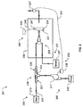
- FIG. 2 shows a schematic view of an abrasive blasting system 201 according to the preferred embodiment of the present application.
- Abrasive blasting system 201 comprises one or more of an air subsystem 203, a fluid subsystem 205, an abrasive media subsystem 207, and a control subsystem 209.
- Abrasive blasting system 201 is further provided with a plurality of conduits 211 utilized to interconnect the subsystems disclosed herein. It should be noted that for simplicity, a single conduit 211 is identified, and for clarity, a plurality of arrows are provided within the plurality of conduits 211 to depict the movement of air, fluid, and abrasive media channeled therein.
- Air subsystem 203 includes a compressor 213 utilized to compress air at predetermined pressure and adapted to direct the air through one or more of the plurality of conduits 211 in communication thereto.
- abrasive blasting system 201 utilizes air; however, it should be appreciated that alternative embodiments could utilize other forms of suitable gases for the abrasive blasting process.
- Fluid subsystem 205 includes a fluid reservoir 215 for storing fluid therein. It should be understood that the fluid from fluid reservoir 215 is utilized to change the relative humidity of the air from air subsystem 213. In the preferred embodiment, the fluid is water; however, alternative embodiments could utilize other different types of suitable fluids adapted to change the relative humidity. Fluid subsystem 205 further includes a pump 217 adapted to pressurize the fluid and adapted to direct the fluid to a mixer 219. Pump 217 is preferably adjustable to provide a desired flow rate, thereby enabling changes to the relative humidity.
- Mixer 219 is adapted to mix air from air subsystem 203 with fluid from fluid subsystem 205.
- air enters mixer 219 through a first chamber 221 having inner walls that taper to increase the air velocity of the air passing therethrough.
- the fluid enters mixer 219 via a second chamber 223 in fluid communication with chamber 221.
- Second chamber 223 is utilized to mix the air with the fluid.
- the mixed air and fluid is further turbulently mixed through a third section 225 adapted compress then expand the fluidly mixed air. Thereafter, the treated air is mixed downstream with the abrasive media from media subsystem 207.
- Media subsystem 207 includes a chamber 227 for storing abrasive media utilized during the abrasive blasting process.
- the abrasive media is channeled through one or more of the plurality of conduits 211 to an abrasive blasting gun 229.
- air, fluid, and media are channeled to gun 229 via the plurality of conduits 211, which in turn blasts the abrasive media on a surface 231 of a structure 233.
- a housing 235 is utilized to hold gun 229 and structure 233 therein and to provide means for containing the blasted abrasive media.
- One or more of the plurality of conduits 211 are utilized to channel exiting air from chamber 235.
- a sensor 237 is in communication with the exiting air and is utilized to sense the relative humidity of the exiting air. Thereafter, sensor 237 relays the sensed relative humidity to a control station 239 via an electrical conductor 241. Based upon the sensed relative humidity, control station 239 adjusts the flow rate of fluid entering mixer 219 by either decreasing or increasing the pump output. It has been observed that the desired relative humidity is approximately 40-50 RH in most applications for eliminating static buildup.
- control subsystem 207 and fluid subsystem 205 are adapted to regulate the relative humidity of abrasive blasting system 201 to any desired relative humidity. It will also be appreciated that sensor 237 is adapted to continuously provide real time data to control station 239, thus allowing continuous adjustment of fluid subsystem 215 such that the desired relative humidity is maintained throughout the blasting process.
- Grounding subsystem 243 includes a grounded structure 245 conductively coupled to an attachment device 247, which in turn is attached to structure 233 via a conductor 249. During operation, the combination of changing the relative humidity and grounding the structure greatly reduces, if not eliminates, the likelihood of electrostatic buildup.
- abrasive blasting system 301 is substantially similar in function to abrasive blasting system 201.
- system 301 is adapted to reduce electrostatic buildup during the blasting process.
- abrasive blasting system 301 includes all features of abrasive blasting system 201 and is further provided with a portable structure 303, which enables abrasive blasting system 301 to perform blasting operations in the field.
- abrasive blasting system 301 could easily be transported to the field for blasting a surface, i.e. a side panel, of a vehicle.
- portable structure 303 is portable per a set of wheels 305 rotatably attached to structure 303; however, it should be appreciated that alternative embodiments could include different structures, for example, a towable trailer, in lieu of the exemplary embodiment.
- Box 403 shows the first step of the process, which includes pressuring the air. This feature is preferably achieved via an air compressor.
- the next step includes regulating the relative humidity of the air, as depicted in boxes 405 and 407. This feature is preferably achieved via the fluid subsystem and control subsystem disclosed herein.
- the abrasive media is mixed with the fluidly compressed air and subsequently blasted on a surface, as depicted in boxes 409 and 411.
- the preferred method is further optionally provided with the process of grounding the structure to reduce the possibility of electrostatic buildup.
Landscapes
- Engineering & Computer Science (AREA)
- Mechanical Engineering (AREA)
- Electrostatic Spraying Apparatus (AREA)
- Nozzles (AREA)
Description
- The present application relates generally to manufacturing systems, and more particularly to abrasive blasting systems.
- Grit-blasting, abrasive blasting, and sandblasting are well known processes in the art for propelling a high pressure stream of abrasive material on a surface, which can either form a smooth surface, a rough surface, or a contoured surface. A problem commonly associated with the abrasive blasting system is electrostatic buildup created by the interaction of the abrasive material and surface applied thereto. The electrostatic buildup could result in serious harm to the worker and/or irreparable damage to the structure.
- Conventional methods to reduce the electrostatic buildup include increasing the relative humidity of the air, on a global scale, within the facility housing the abrasive blasting system. For example, a humidity control system and/or a HVAC system can be utilized to increase the relative humidity of the air, thereby reducing the likelihood of electrostatic buildup. However, such features are not ideal in most scenarios due to the increased costs associated with continuously running and maintaining the HVAC system.
- Known examples of abrasive blasting devices are described in
WO 93/09915 US 6174225 . InWO 93/09915 - In
US 6174225 , a device for removing surface coverings comprises a feeder device capable of providing a supply of dry ice pieces, a pellet-size reducer operatively associated with the feeder device to receive dry ice pieces from said feeder device and reduce the size of the dry ice pieces to nominal diameters less than 1 mm, and a blast gun connected to the pellet-size reducer and adapted for operative communication with an associated supply of flowing gas. The device may include a humidity controller to suppress static charges caused by the interaction of the dry ice particles with the surface being blasted, the humidity controller monitoring the humidity of the gas stream before it exits the blast gun. - Although the foregoing developments represent great strides in the area of reducing electrostatic buildup, many shortcomings remain.
- The present invention provides an abrasive blasting system according to claim 1 and a method to reduce electrostatic buildup during abrasive blasting according to claim 11. The dependent claims refer to preferred embodiments of the invention.
- The novel features believed characteristic of the application are set forth in the appended claims. However, the application itself, as well as a preferred mode of use, and further objectives and advantages thereof, will best be understood with reference to the following detailed description when read in conjunction with the accompanying drawings, wherein:
-
Figure 1 is a front view of a facility having a conventional abrasive blasting system; -
Figure 2 is a schematic view of an abrasive blasting system according to the preferred embodiment of the present application; -
Figure 3 is a side view of an alternative embodiment of the abrasive blasting system ofFigure 2 ; and -
Figure 4 is a flow chart depicting the preferred method to reduce electrostatic buildup during the abrasive blasting process. - While the system and method of the present application is susceptible to various modifications and alternative forms, specific embodiments thereof have been shown by way of example in the drawings and are herein described in detail. It should be understood, however, that the description herein of specific embodiments is not intended to limit the invention to the particular embodiment disclosed, but on the contrary, the intention is to cover all modifications, equivalents, and alternatives falling within the scope of the invention as defined by the appended claims.
- The system and method of the present application greatly reduces, if not eliminates, static buildup during abrasive blasting. Specifically, the abrasive blasting system utilizes a fluid subsystem adapted to locally increase the relative humidity of the air passing through the abrasive blasting system. The system is further provided with a relative humidity control subsystem in communication with the air, which constantly monitors and regulates the relative humidity. Furthermore, the system is optionally provided with a grounding subsystem adapted to electrically ground the blasted structure, thus further reducing the possibility of electrostatic buildup. In one embodiment, the abrasive blasting system is portable, thereby enabling a worker transport the system to the location of use.
- It will of course be appreciated that in the development of any actual embodiment, numerous implementation-specific decisions will be made to achieve the developer's specific goals, such as compliance with system-related and business-related constraints, which will vary from one implementation to another. Moreover, it will be appreciated that such a development effort might be complex and time-consuming, but would nevertheless be a routine undertaking for those of ordinary skill in the art having the benefit of this disclosure.
- Referring now to the drawings,
Figure 1 depicts aconventional system 101 utilized to reduce electrostatic buildup during the abrasive blasting process. In the exemplary embodiment, afacility 103 stores aconventional blasting system 105 therein. Prior to blasting, a HVAC and/orhumidity regulator system 107 regulates the relative humidity of the air, on a global scale, withinfacility 103. For clarity, a plurality ofarrows 109 depict the continuous circulation of air through theHVAC system 107 andfacility 103. -
Figure 1 provides clarification of some problems commonly associated with conventional blasting systems. In particular,HVAC system 107 regulates the relative humidity of the air by continuously recycling the large body of air withinfacility 103. In most large facilities, this process is very time consuming and costly. In addition, the HVAC system must cycle the majority, if not all, the air prior to blasting, which requires considerable time prior to operation. - Another common problem associated with
system 101 is creating uniform relative humidity within the facility. For example, a large facility could include areas wherein the outside air enters through one or more entrances, i.e., a door left ajar, windows, crevices, and/or any other type of entrance, which greatly changes the relative humidity around these areas. It is difficult, if not impossible, to regulate the relative humidity in larger facilities without the use of large energy consuming HVAC systems. The abrasive blasting system of the present application overcomes these problems by locally changing the relative humidity of the air entering the system. Further illustration and description of the preferred embodiment of the abrasive blasting system is provided below. -
Figure 2 shows a schematic view of anabrasive blasting system 201 according to the preferred embodiment of the present application.Abrasive blasting system 201 comprises one or more of anair subsystem 203, afluid subsystem 205, anabrasive media subsystem 207, and acontrol subsystem 209.Abrasive blasting system 201 is further provided with a plurality ofconduits 211 utilized to interconnect the subsystems disclosed herein. It should be noted that for simplicity, asingle conduit 211 is identified, and for clarity, a plurality of arrows are provided within the plurality ofconduits 211 to depict the movement of air, fluid, and abrasive media channeled therein. -
Air subsystem 203 includes acompressor 213 utilized to compress air at predetermined pressure and adapted to direct the air through one or more of the plurality ofconduits 211 in communication thereto. In the preferred embodiment,abrasive blasting system 201 utilizes air; however, it should be appreciated that alternative embodiments could utilize other forms of suitable gases for the abrasive blasting process. -
Fluid subsystem 205 includes afluid reservoir 215 for storing fluid therein. It should be understood that the fluid fromfluid reservoir 215 is utilized to change the relative humidity of the air fromair subsystem 213. In the preferred embodiment, the fluid is water; however, alternative embodiments could utilize other different types of suitable fluids adapted to change the relative humidity.Fluid subsystem 205 further includes apump 217 adapted to pressurize the fluid and adapted to direct the fluid to a mixer 219.Pump 217 is preferably adjustable to provide a desired flow rate, thereby enabling changes to the relative humidity. - Mixer 219 is adapted to mix air from
air subsystem 203 with fluid fromfluid subsystem 205. During operation, air enters mixer 219 through afirst chamber 221 having inner walls that taper to increase the air velocity of the air passing therethrough. The fluid enters mixer 219 via asecond chamber 223 in fluid communication withchamber 221.Second chamber 223 is utilized to mix the air with the fluid. The mixed air and fluid is further turbulently mixed through athird section 225 adapted compress then expand the fluidly mixed air. Thereafter, the treated air is mixed downstream with the abrasive media frommedia subsystem 207. -
Media subsystem 207 includes achamber 227 for storing abrasive media utilized during the abrasive blasting process. The abrasive media is channeled through one or more of the plurality ofconduits 211 to anabrasive blasting gun 229. During operation, air, fluid, and media are channeled togun 229 via the plurality ofconduits 211, which in turn blasts the abrasive media on asurface 231 of astructure 233. - A
housing 235 is utilized to holdgun 229 andstructure 233 therein and to provide means for containing the blasted abrasive media. One or more of the plurality ofconduits 211 are utilized to channel exiting air fromchamber 235. Asensor 237 is in communication with the exiting air and is utilized to sense the relative humidity of the exiting air. Thereafter,sensor 237 relays the sensed relative humidity to acontrol station 239 via anelectrical conductor 241. Based upon the sensed relative humidity,control station 239 adjusts the flow rate of fluid entering mixer 219 by either decreasing or increasing the pump output. It has been observed that the desired relative humidity is approximately 40-50 RH in most applications for eliminating static buildup. It should be appreciated thatcontrol subsystem 207 andfluid subsystem 205 are adapted to regulate the relative humidity ofabrasive blasting system 201 to any desired relative humidity. It will also be appreciated thatsensor 237 is adapted to continuously provide real time data to controlstation 239, thus allowing continuous adjustment offluid subsystem 215 such that the desired relative humidity is maintained throughout the blasting process. -
Abrasive blasting system 201 is further provided with grounding subsystem 243 adapted to further reduce the likelihood of electrostatic buildup. Grounding subsystem 243 includes a groundedstructure 245 conductively coupled to anattachment device 247, which in turn is attached to structure 233 via aconductor 249. During operation, the combination of changing the relative humidity and grounding the structure greatly reduces, if not eliminates, the likelihood of electrostatic buildup. - Referring to
Figure 3 in the drawings, an alternative embodiment ofabrasive blasting system 201 is shown.Abrasive blasting system 301 is substantially similar in function toabrasive blasting system 201. In particular,system 301 is adapted to reduce electrostatic buildup during the blasting process. It should be understood thatabrasive blasting system 301 includes all features ofabrasive blasting system 201 and is further provided with aportable structure 303, which enablesabrasive blasting system 301 to perform blasting operations in the field. For example,abrasive blasting system 301 could easily be transported to the field for blasting a surface, i.e. a side panel, of a vehicle. In the exemplary embodiment,portable structure 303 is portable per a set ofwheels 305 rotatably attached to structure 303; however, it should be appreciated that alternative embodiments could include different structures, for example, a towable trailer, in lieu of the exemplary embodiment. - Referring now to
Figure 4 in the drawings, aflow chart 401 depicting the preferred abrasive blasting process is shown.Box 403 shows the first step of the process, which includes pressuring the air. This feature is preferably achieved via an air compressor. The next step includes regulating the relative humidity of the air, as depicted inboxes boxes - It is apparent that a system and method having significant advantages has been described and illustrated. The particular embodiments disclosed above are illustrative only, as the embodiments may be modified and practiced in different but equivalent manners apparent to those skilled in the art having the benefit of the teachings herein. It is therefore evident that the particular embodiments disclosed above may be altered or modified, without departing from the scope of the invention as defined by the appended claims.
Claims (15)
- An abrasive blasting system (201), comprising:an air subsystem (203) being adapted to provide pressurized air;a fluid subsystem (205) being adapted to provide fluid;a mixer (219) being adapted to combine and mix the fluid with the pressurized air, thus changing the relative humidity of the pressurized air; and wherein the mixer (219) has an inner contouring to compress and expand the fluid and the pressurized air, thus turbulently mixing the fluid and the pressurized air together;a media subsystem (207) being adapted to provide abrasive media which mixes with the pressurized air and the fluid;a housing (235) being adapted to hold an abrasive blasting gun (229) and a blasting structure (233) and to contain abrasive media blasted on a surface (231) of the structure (233) via the gun (229); anda control subsystem (209) adapted to regulate the relative humidity of the pressurized air and having a control station (239) operably associated with the fluid subsystem (205) and in data communication with a sensor (237),characterised in thatthe sensor (237) is in communication with the pressurized air exiting the housing (235), and is adapted to sense the relative humidity of the exiting air.
- The abrasive blasting system of claim 1, further comprising:a grounding subsystem (243), having:a grounded structure (245); andan attachment device (247) being attached to the structure (245) and being conductively coupled to the grounded structure (245) via an electrical conductor (249).
- The abrasive blasting system of claim 1, the fluid subsystem (205) comprising:a pump (217) being adapted to provide a flow rate of fluid to the mixer (219), the pump (217) being operably associated with the control station (239) such that the control station (239) adjusts the flow rate based upon the sensed relative humidity of the exiting air.
- The abrasive blasting system of claim 1, the fluid subsystem (205) comprising:a pump (217) being adapted to provide fluid to the mixer (219).
- The abrasive blasting system of claim 1, the mixer (219) comprising:a first chamber (221) in communication with the air subsystem (203), the first chamber (221) being adapted to increase the air velocity of the air entering therein;a second chamber (223) in communication with the first chamber (221) and in fluid communication with the fluid subsystem (205), the second chamber (223) being adapted to mix the pressurized air with the fluid; anda third chamber (225) in fluid communication with the second chamber (223), the third chamber (225) being adapted to contract and then expand the air and the fluid channeled therethrough.
- The abrasive blasting system of claim 1, further comprising:portable structure (303) adapted to carry the air subsystem (203), the fluid subsystem (205), the mixer (219), the control subsystem (209), and the media subsystem (207) to the place of use.
- The abrasive blasting system of claim 6, further comprising:a grounding subsystem (243), having:a grounded structure (245); andan attachment device (247) being attached to the grounded structure (245) and being conductively coupled to the grounded structure (245) via an electrical conductor (249).
- The abrasive blasting system of claim 6, the fluid subsystem (205) comprising:a pump (217) being adapted to provide a flow rate of fluid to the mixer (219), the pump (217) being operably associated with the control station (239) such that the control station (239) adjusts the flow rate based upon the sensed relative humidity of the exiting air.
- The abrasive blasting system of claim 6, the fluid subsystem (205) comprising:a pump (217) being adapted to provide fluid to the mixer (219).
- The abrasive blasting system of claim 6, the mixer (219) comprising:a first chamber (221) in communication with the air subsystem (203), the first chamber (221) being adapted to increase the air velocity of the air entering therein;a second chamber (223) in communication with the first chamber (221) and in fluid communication with the fluid subsystem (205), the second chamber (223) being adapted to mix the pressurized air with the fluid; anda third chamber (225) in fluid communication with a the second chamber, the third chamber (225) being adapted to contract and then expand the air and the fluid channeled therethrough.
- A method to reduce electrostatic buildup during abrasive blasting on a surface (231) of a structure (233) using an abrasive blasting system according to claim 1, the method comprising:pressurizing (403) air with the air subsystem (203);sensing (405) the relative humidity of the pressurized air with the control subsystem (209);turbulently mixing fluid with the pressurized air with the mixer (219) configured to compress and expand the fluid and the pressurized air together;regulating (407) the amount of fluid mixed with the pressurized air based upon the sensed relative humidity;mixing (409) the abrasive media with the pressurized air mixed with the fluid; andblasting (441), via the blasting gun (229), the surface (231) of the structure (233) with the abrasive media mixed with the fluid and the pressurized air,characterised in that the sensing (405) is achieved by sensing the relative humidity of the pressurized air exiting the housing (235) by a sensor (237) in communication with the exiting air.
- The method of claim 11, wherein the regulating (407) of the amount of fluid is achieved by controlling the flow rate of the fluid with an adjustable pump (217).
- The method of claim 12, wherein the process of regulating (407) the amount of fluid is further achieved by:relaying the sensed relative humidity to a control station (239) operably associated with the adjustable pump (217); andadjusting the flow rate of fluid from the pump (217) with the control station (239) based upon the sensed relative humidity.
- The method of claim 11, further comprising:transporting the air subsystem (203), the control subsystem (209), the mixer (219), and the abrasive media via a portable structure (303) to the surface (231) of the structure (233).
- The method of claim 11, further comprising:electrically grounding the structure (233) with a grounding subsystem (243).
Applications Claiming Priority (1)
| Application Number | Priority Date | Filing Date | Title |
|---|---|---|---|
| PCT/US2011/044044 WO2013009320A1 (en) | 2011-07-14 | 2011-07-14 | Humidity control for abrasive blasting systems |
Publications (3)
| Publication Number | Publication Date |
|---|---|
| EP2709798A1 EP2709798A1 (en) | 2014-03-26 |
| EP2709798A4 EP2709798A4 (en) | 2015-03-25 |
| EP2709798B1 true EP2709798B1 (en) | 2016-01-20 |
Family
ID=47506355
Family Applications (1)
| Application Number | Title | Priority Date | Filing Date |
|---|---|---|---|
| EP11869432.2A Active EP2709798B1 (en) | 2011-07-14 | 2011-07-14 | Humidity control for abrasive blasting systems |
Country Status (5)
| Country | Link |
|---|---|
| US (1) | US9168635B2 (en) |
| EP (1) | EP2709798B1 (en) |
| CN (1) | CN103717352B (en) |
| CA (1) | CA2841444C (en) |
| WO (1) | WO2013009320A1 (en) |
Families Citing this family (1)
| Publication number | Priority date | Publication date | Assignee | Title |
|---|---|---|---|---|
| CN110788764B (en) * | 2019-09-23 | 2022-06-28 | 马鞍山市皖晓旅游用品制造有限责任公司 | Wet-type sand blasting device |
Family Cites Families (10)
| Publication number | Priority date | Publication date | Assignee | Title |
|---|---|---|---|---|
| US4406505A (en) * | 1981-02-18 | 1983-09-27 | Daniel Woodhead, Inc. | Grounding clip for electrical fixtures |
| US5230185A (en) | 1990-04-06 | 1993-07-27 | Church & Dwight Co., Inc. | Blasting apparatus and method |
| US6174225B1 (en) * | 1997-11-13 | 2001-01-16 | Waste Minimization And Containment Inc. | Dry ice pellet surface removal apparatus and method |
| JP3846842B2 (en) | 2000-10-16 | 2006-11-15 | 新東工業株式会社 | Humidity maintenance device in air blast equipment |
| US20030224704A1 (en) * | 2002-05-28 | 2003-12-04 | James Shank | Rotary media valve |
| DE60313981T2 (en) | 2002-07-23 | 2008-01-24 | Grechishkin, Oleg Ivanovich | SPIN JET DEVICE |
| CN1597252A (en) * | 2004-08-25 | 2005-03-23 | 董金奎 | Sand blower |
| GB0500649D0 (en) | 2005-01-14 | 2005-02-23 | Exa Sa | Dosing device for a particle blasting apparatus |
| US20080176487A1 (en) * | 2007-01-19 | 2008-07-24 | Armstrong Jay T | Portable cleaning and blasting system for multiple media types, including dry ice and grit |
| US9058707B2 (en) | 2009-02-17 | 2015-06-16 | Ronald C. Benson | System and method for managing and maintaining abrasive blasting machines |
-
2011
- 2011-07-14 WO PCT/US2011/044044 patent/WO2013009320A1/en not_active Ceased
- 2011-07-14 CN CN201180072297.7A patent/CN103717352B/en not_active Expired - Fee Related
- 2011-07-14 US US13/703,644 patent/US9168635B2/en active Active
- 2011-07-14 EP EP11869432.2A patent/EP2709798B1/en active Active
- 2011-07-14 CA CA2841444A patent/CA2841444C/en active Active
Also Published As
| Publication number | Publication date |
|---|---|
| CN103717352A (en) | 2014-04-09 |
| WO2013009320A1 (en) | 2013-01-17 |
| US9168635B2 (en) | 2015-10-27 |
| EP2709798A4 (en) | 2015-03-25 |
| CA2841444C (en) | 2017-05-09 |
| US20130143470A1 (en) | 2013-06-06 |
| EP2709798A1 (en) | 2014-03-26 |
| CN103717352B (en) | 2017-02-15 |
| CA2841444A1 (en) | 2013-01-17 |
Similar Documents
| Publication | Publication Date | Title |
|---|---|---|
| US5230185A (en) | Blasting apparatus and method | |
| US5947800A (en) | Pneumatic suction surface blasting apparatus with an improved media delivery regulating system | |
| US9925642B2 (en) | Wet abrasive blasting system and method | |
| US5081799A (en) | Blasting apparatus | |
| US4545317A (en) | Device for treating the surfaces of structures and ships | |
| CN106573741B (en) | Pneumatic conveying device | |
| US11548115B2 (en) | Dry wet blast media blasting system | |
| US10076823B2 (en) | Wet abrasive blasting system and method | |
| WO1991015336A1 (en) | Improvement in blasting apparatus | |
| CN104875119A (en) | Ship coating sand blasting machine and sand blasting method | |
| CN105500219A (en) | Pneumatic water mist rust and paint removing device and rust and paint removing method | |
| CA2841444C (en) | Humidity control for abrasive blasting systems | |
| CA1321478C (en) | Particle blast cleaning and treating of surfaces | |
| JPS5934605B2 (en) | constant flow transport device | |
| EP0708699A1 (en) | Blasting device with adjustable blast strength | |
| CN108188937B (en) | Wet-type press-in deburring sand blasting machine | |
| CN203962024U (en) | A kind of for belt-conveying lane automatic spray dust removal device under coal mine | |
| US3322351A (en) | Apparatus for spraying fluent materials | |
| CN108025199A (en) | For generating the apparatus and method and fire-fighting equipment of fire-fighting compressed-air foam | |
| KR101077669B1 (en) | Air Sand Blast Machine Abrasive Material Supply Device | |
| KR20180127166A (en) | Hopper device | |
| CN219340951U (en) | Integrated high-pressure pneumatic conveying and sending station | |
| WO2006122281A2 (en) | Fluid line clearing system | |
| CN206122018U (en) | Full -automatic intelligent painting robot equipment | |
| CN108144430B (en) | Flue gas denitration urea metering injection system and method |
Legal Events
| Date | Code | Title | Description |
|---|---|---|---|
| PUAI | Public reference made under article 153(3) epc to a published international application that has entered the european phase |
Free format text: ORIGINAL CODE: 0009012 |
|
| 17P | Request for examination filed |
Effective date: 20131216 |
|
| AK | Designated contracting states |
Kind code of ref document: A1 Designated state(s): AL AT BE BG CH CY CZ DE DK EE ES FI FR GB GR HR HU IE IS IT LI LT LU LV MC MK MT NL NO PL PT RO RS SE SI SK SM TR |
|
| RIN1 | Information on inventor provided before grant (corrected) |
Inventor name: AMERSON, JIMMY, D. Inventor name: BISHOP, STEPHEN Inventor name: MILLICAN, STEVEN |
|
| DAX | Request for extension of the european patent (deleted) | ||
| A4 | Supplementary search report drawn up and despatched |
Effective date: 20150224 |
|
| RIC1 | Information provided on ipc code assigned before grant |
Ipc: B24C 5/04 20060101AFI20150218BHEP Ipc: B24C 7/00 20060101ALI20150218BHEP Ipc: B24C 5/02 20060101ALI20150218BHEP |
|
| 17Q | First examination report despatched |
Effective date: 20150730 |
|
| GRAP | Despatch of communication of intention to grant a patent |
Free format text: ORIGINAL CODE: EPIDOSNIGR1 |
|
| GRAS | Grant fee paid |
Free format text: ORIGINAL CODE: EPIDOSNIGR3 |
|
| INTG | Intention to grant announced |
Effective date: 20151105 |
|
| GRAA | (expected) grant |
Free format text: ORIGINAL CODE: 0009210 |
|
| AK | Designated contracting states |
Kind code of ref document: B1 Designated state(s): AL AT BE BG CH CY CZ DE DK EE ES FI FR GB GR HR HU IE IS IT LI LT LU LV MC MK MT NL NO PL PT RO RS SE SI SK SM TR |
|
| REG | Reference to a national code |
Ref country code: GB Ref legal event code: FG4D |
|
| REG | Reference to a national code |
Ref country code: CH Ref legal event code: EP |
|
| REG | Reference to a national code |
Ref country code: IE Ref legal event code: FG4D |
|
| REG | Reference to a national code |
Ref country code: AT Ref legal event code: REF Ref document number: 771473 Country of ref document: AT Kind code of ref document: T Effective date: 20160215 |
|
| REG | Reference to a national code |
Ref country code: DE Ref legal event code: R096 Ref document number: 602011022923 Country of ref document: DE |
|
| REG | Reference to a national code |
Ref country code: LT Ref legal event code: MG4D Ref country code: NL Ref legal event code: MP Effective date: 20160120 |
|
| REG | Reference to a national code |
Ref country code: AT Ref legal event code: MK05 Ref document number: 771473 Country of ref document: AT Kind code of ref document: T Effective date: 20160120 |
|
| PG25 | Lapsed in a contracting state [announced via postgrant information from national office to epo] |
Ref country code: NL Free format text: LAPSE BECAUSE OF FAILURE TO SUBMIT A TRANSLATION OF THE DESCRIPTION OR TO PAY THE FEE WITHIN THE PRESCRIBED TIME-LIMIT Effective date: 20160120 |
|
| REG | Reference to a national code |
Ref country code: FR Ref legal event code: PLFP Year of fee payment: 6 |
|
| PG25 | Lapsed in a contracting state [announced via postgrant information from national office to epo] |
Ref country code: FI Free format text: LAPSE BECAUSE OF FAILURE TO SUBMIT A TRANSLATION OF THE DESCRIPTION OR TO PAY THE FEE WITHIN THE PRESCRIBED TIME-LIMIT Effective date: 20160120 Ref country code: HR Free format text: LAPSE BECAUSE OF FAILURE TO SUBMIT A TRANSLATION OF THE DESCRIPTION OR TO PAY THE FEE WITHIN THE PRESCRIBED TIME-LIMIT Effective date: 20160120 Ref country code: GR Free format text: LAPSE BECAUSE OF FAILURE TO SUBMIT A TRANSLATION OF THE DESCRIPTION OR TO PAY THE FEE WITHIN THE PRESCRIBED TIME-LIMIT Effective date: 20160421 Ref country code: NO Free format text: LAPSE BECAUSE OF FAILURE TO SUBMIT A TRANSLATION OF THE DESCRIPTION OR TO PAY THE FEE WITHIN THE PRESCRIBED TIME-LIMIT Effective date: 20160420 Ref country code: ES Free format text: LAPSE BECAUSE OF FAILURE TO SUBMIT A TRANSLATION OF THE DESCRIPTION OR TO PAY THE FEE WITHIN THE PRESCRIBED TIME-LIMIT Effective date: 20160120 |
|
| PG25 | Lapsed in a contracting state [announced via postgrant information from national office to epo] |
Ref country code: LT Free format text: LAPSE BECAUSE OF FAILURE TO SUBMIT A TRANSLATION OF THE DESCRIPTION OR TO PAY THE FEE WITHIN THE PRESCRIBED TIME-LIMIT Effective date: 20160120 Ref country code: LV Free format text: LAPSE BECAUSE OF FAILURE TO SUBMIT A TRANSLATION OF THE DESCRIPTION OR TO PAY THE FEE WITHIN THE PRESCRIBED TIME-LIMIT Effective date: 20160120 Ref country code: AT Free format text: LAPSE BECAUSE OF FAILURE TO SUBMIT A TRANSLATION OF THE DESCRIPTION OR TO PAY THE FEE WITHIN THE PRESCRIBED TIME-LIMIT Effective date: 20160120 Ref country code: RS Free format text: LAPSE BECAUSE OF FAILURE TO SUBMIT A TRANSLATION OF THE DESCRIPTION OR TO PAY THE FEE WITHIN THE PRESCRIBED TIME-LIMIT Effective date: 20160120 Ref country code: PT Free format text: LAPSE BECAUSE OF FAILURE TO SUBMIT A TRANSLATION OF THE DESCRIPTION OR TO PAY THE FEE WITHIN THE PRESCRIBED TIME-LIMIT Effective date: 20160520 Ref country code: PL Free format text: LAPSE BECAUSE OF FAILURE TO SUBMIT A TRANSLATION OF THE DESCRIPTION OR TO PAY THE FEE WITHIN THE PRESCRIBED TIME-LIMIT Effective date: 20160120 Ref country code: SE Free format text: LAPSE BECAUSE OF FAILURE TO SUBMIT A TRANSLATION OF THE DESCRIPTION OR TO PAY THE FEE WITHIN THE PRESCRIBED TIME-LIMIT Effective date: 20160120 Ref country code: IS Free format text: LAPSE BECAUSE OF FAILURE TO SUBMIT A TRANSLATION OF THE DESCRIPTION OR TO PAY THE FEE WITHIN THE PRESCRIBED TIME-LIMIT Effective date: 20160520 |
|
| REG | Reference to a national code |
Ref country code: DE Ref legal event code: R097 Ref document number: 602011022923 Country of ref document: DE |
|
| PG25 | Lapsed in a contracting state [announced via postgrant information from national office to epo] |
Ref country code: DK Free format text: LAPSE BECAUSE OF FAILURE TO SUBMIT A TRANSLATION OF THE DESCRIPTION OR TO PAY THE FEE WITHIN THE PRESCRIBED TIME-LIMIT Effective date: 20160120 Ref country code: EE Free format text: LAPSE BECAUSE OF FAILURE TO SUBMIT A TRANSLATION OF THE DESCRIPTION OR TO PAY THE FEE WITHIN THE PRESCRIBED TIME-LIMIT Effective date: 20160120 |
|
| PLBE | No opposition filed within time limit |
Free format text: ORIGINAL CODE: 0009261 |
|
| STAA | Information on the status of an ep patent application or granted ep patent |
Free format text: STATUS: NO OPPOSITION FILED WITHIN TIME LIMIT |
|
| PG25 | Lapsed in a contracting state [announced via postgrant information from national office to epo] |
Ref country code: RO Free format text: LAPSE BECAUSE OF FAILURE TO SUBMIT A TRANSLATION OF THE DESCRIPTION OR TO PAY THE FEE WITHIN THE PRESCRIBED TIME-LIMIT Effective date: 20160120 Ref country code: SK Free format text: LAPSE BECAUSE OF FAILURE TO SUBMIT A TRANSLATION OF THE DESCRIPTION OR TO PAY THE FEE WITHIN THE PRESCRIBED TIME-LIMIT Effective date: 20160120 Ref country code: CZ Free format text: LAPSE BECAUSE OF FAILURE TO SUBMIT A TRANSLATION OF THE DESCRIPTION OR TO PAY THE FEE WITHIN THE PRESCRIBED TIME-LIMIT Effective date: 20160120 Ref country code: SM Free format text: LAPSE BECAUSE OF FAILURE TO SUBMIT A TRANSLATION OF THE DESCRIPTION OR TO PAY THE FEE WITHIN THE PRESCRIBED TIME-LIMIT Effective date: 20160120 |
|
| 26N | No opposition filed |
Effective date: 20161021 |
|
| PG25 | Lapsed in a contracting state [announced via postgrant information from national office to epo] |
Ref country code: BE Free format text: LAPSE BECAUSE OF FAILURE TO SUBMIT A TRANSLATION OF THE DESCRIPTION OR TO PAY THE FEE WITHIN THE PRESCRIBED TIME-LIMIT Effective date: 20160120 |
|
| PG25 | Lapsed in a contracting state [announced via postgrant information from national office to epo] |
Ref country code: BG Free format text: LAPSE BECAUSE OF FAILURE TO SUBMIT A TRANSLATION OF THE DESCRIPTION OR TO PAY THE FEE WITHIN THE PRESCRIBED TIME-LIMIT Effective date: 20160420 Ref country code: SI Free format text: LAPSE BECAUSE OF FAILURE TO SUBMIT A TRANSLATION OF THE DESCRIPTION OR TO PAY THE FEE WITHIN THE PRESCRIBED TIME-LIMIT Effective date: 20160120 |
|
| REG | Reference to a national code |
Ref country code: CH Ref legal event code: PL |
|
| PG25 | Lapsed in a contracting state [announced via postgrant information from national office to epo] |
Ref country code: MC Free format text: LAPSE BECAUSE OF FAILURE TO SUBMIT A TRANSLATION OF THE DESCRIPTION OR TO PAY THE FEE WITHIN THE PRESCRIBED TIME-LIMIT Effective date: 20160120 |
|
| PG25 | Lapsed in a contracting state [announced via postgrant information from national office to epo] |
Ref country code: CH Free format text: LAPSE BECAUSE OF NON-PAYMENT OF DUE FEES Effective date: 20160731 Ref country code: LI Free format text: LAPSE BECAUSE OF NON-PAYMENT OF DUE FEES Effective date: 20160731 |
|
| REG | Reference to a national code |
Ref country code: IE Ref legal event code: MM4A |
|
| REG | Reference to a national code |
Ref country code: FR Ref legal event code: PLFP Year of fee payment: 7 |
|
| PG25 | Lapsed in a contracting state [announced via postgrant information from national office to epo] |
Ref country code: IE Free format text: LAPSE BECAUSE OF NON-PAYMENT OF DUE FEES Effective date: 20160714 |
|
| PG25 | Lapsed in a contracting state [announced via postgrant information from national office to epo] |
Ref country code: LU Free format text: LAPSE BECAUSE OF NON-PAYMENT OF DUE FEES Effective date: 20160714 |
|
| PG25 | Lapsed in a contracting state [announced via postgrant information from national office to epo] |
Ref country code: HU Free format text: LAPSE BECAUSE OF FAILURE TO SUBMIT A TRANSLATION OF THE DESCRIPTION OR TO PAY THE FEE WITHIN THE PRESCRIBED TIME-LIMIT; INVALID AB INITIO Effective date: 20110714 Ref country code: CY Free format text: LAPSE BECAUSE OF FAILURE TO SUBMIT A TRANSLATION OF THE DESCRIPTION OR TO PAY THE FEE WITHIN THE PRESCRIBED TIME-LIMIT Effective date: 20160120 |
|
| PG25 | Lapsed in a contracting state [announced via postgrant information from national office to epo] |
Ref country code: MK Free format text: LAPSE BECAUSE OF FAILURE TO SUBMIT A TRANSLATION OF THE DESCRIPTION OR TO PAY THE FEE WITHIN THE PRESCRIBED TIME-LIMIT Effective date: 20160120 Ref country code: MT Free format text: LAPSE BECAUSE OF NON-PAYMENT OF DUE FEES Effective date: 20160731 |
|
| REG | Reference to a national code |
Ref country code: FR Ref legal event code: PLFP Year of fee payment: 8 |
|
| PG25 | Lapsed in a contracting state [announced via postgrant information from national office to epo] |
Ref country code: TR Free format text: LAPSE BECAUSE OF FAILURE TO SUBMIT A TRANSLATION OF THE DESCRIPTION OR TO PAY THE FEE WITHIN THE PRESCRIBED TIME-LIMIT Effective date: 20160120 Ref country code: AL Free format text: LAPSE BECAUSE OF FAILURE TO SUBMIT A TRANSLATION OF THE DESCRIPTION OR TO PAY THE FEE WITHIN THE PRESCRIBED TIME-LIMIT Effective date: 20160120 |
|
| PGFP | Annual fee paid to national office [announced via postgrant information from national office to epo] |
Ref country code: IT Payment date: 20210721 Year of fee payment: 11 |
|
| PGFP | Annual fee paid to national office [announced via postgrant information from national office to epo] |
Ref country code: GB Payment date: 20210727 Year of fee payment: 11 Ref country code: DE Payment date: 20210728 Year of fee payment: 11 |
|
| REG | Reference to a national code |
Ref country code: DE Ref legal event code: R119 Ref document number: 602011022923 Country of ref document: DE |
|
| GBPC | Gb: european patent ceased through non-payment of renewal fee |
Effective date: 20220714 |
|
| PG25 | Lapsed in a contracting state [announced via postgrant information from national office to epo] |
Ref country code: GB Free format text: LAPSE BECAUSE OF NON-PAYMENT OF DUE FEES Effective date: 20220714 Ref country code: DE Free format text: LAPSE BECAUSE OF NON-PAYMENT OF DUE FEES Effective date: 20230201 |
|
| P01 | Opt-out of the competence of the unified patent court (upc) registered |
Effective date: 20230602 |
|
| PG25 | Lapsed in a contracting state [announced via postgrant information from national office to epo] |
Ref country code: IT Free format text: LAPSE BECAUSE OF NON-PAYMENT OF DUE FEES Effective date: 20220714 |
|
| PGFP | Annual fee paid to national office [announced via postgrant information from national office to epo] |
Ref country code: FR Payment date: 20250725 Year of fee payment: 15 |