EP2709553B1 - Dental superstructure attaching system and method for attaching a dental superstructure to a dental implant - Google Patents
Dental superstructure attaching system and method for attaching a dental superstructure to a dental implant Download PDFInfo
- Publication number
- EP2709553B1 EP2709553B1 EP12722146.3A EP12722146A EP2709553B1 EP 2709553 B1 EP2709553 B1 EP 2709553B1 EP 12722146 A EP12722146 A EP 12722146A EP 2709553 B1 EP2709553 B1 EP 2709553B1
- Authority
- EP
- European Patent Office
- Prior art keywords
- longitudinal
- superstructure
- dental
- implant
- dental superstructure
- Prior art date
- Legal status (The legal status is an assumption and is not a legal conclusion. Google has not performed a legal analysis and makes no representation as to the accuracy of the status listed.)
- Active
Links
Images

Classifications
-
- A—HUMAN NECESSITIES
- A61—MEDICAL OR VETERINARY SCIENCE; HYGIENE
- A61C—DENTISTRY; APPARATUS OR METHODS FOR ORAL OR DENTAL HYGIENE
- A61C8/00—Means to be fixed to the jaw-bone for consolidating natural teeth or for fixing dental prostheses thereon; Dental implants; Implanting tools
- A61C8/0048—Connecting the upper structure to the implant, e.g. bridging bars
- A61C8/005—Connecting devices for joining an upper structure with an implant member, e.g. spacers
- A61C8/0053—Connecting devices for joining an upper structure with an implant member, e.g. spacers with angular adjustment means, e.g. ball and socket joint
-
- A—HUMAN NECESSITIES
- A61—MEDICAL OR VETERINARY SCIENCE; HYGIENE
- A61C—DENTISTRY; APPARATUS OR METHODS FOR ORAL OR DENTAL HYGIENE
- A61C8/00—Means to be fixed to the jaw-bone for consolidating natural teeth or for fixing dental prostheses thereon; Dental implants; Implanting tools
- A61C8/0048—Connecting the upper structure to the implant, e.g. bridging bars
- A61C8/005—Connecting devices for joining an upper structure with an implant member, e.g. spacers
- A61C8/0065—Connecting devices for joining an upper structure with an implant member, e.g. spacers with expandable or compressible means
-
- A—HUMAN NECESSITIES
- A61—MEDICAL OR VETERINARY SCIENCE; HYGIENE
- A61C—DENTISTRY; APPARATUS OR METHODS FOR ORAL OR DENTAL HYGIENE
- A61C8/00—Means to be fixed to the jaw-bone for consolidating natural teeth or for fixing dental prostheses thereon; Dental implants; Implanting tools
- A61C8/0048—Connecting the upper structure to the implant, e.g. bridging bars
- A61C8/005—Connecting devices for joining an upper structure with an implant member, e.g. spacers
- A61C8/0068—Connecting devices for joining an upper structure with an implant member, e.g. spacers with an additional screw
Definitions
- the present invention pertains to a dental superstructure attaching system for use with a dental implant. More specifically the present invention pertains to a system to be arranged in between a dental implant and a dental superstructure/framework, members thereof, and methods for attaching a dental superstructure to a dental implant via such a system.
- a dental implant system The goal of a dental implant system is to restore the patient to normal function, comfort, aesthetic, speech and health regardless of the current oral condition.
- These implant systems are based on the implantation of dental implants, such as dental implants made of biocompatible titanium, through insertion into the patient's jawbone.
- dental implants such as dental implants made of biocompatible titanium
- biocompatible titanium started in Sweden as early as 1950, and has since then been further developed and spread world-wide.
- a number of implant systems entered the world market.
- WO01/70127 describes an arrangement comprising a spacer element for an implant.
- the spacer implant has a screw bore at a fixed angle relative the longitudinal axis of the implant, such that a holder configured to support a superstructure may be mounted in said screw bore at the corresponding angle.
- the mouth of the connection channel between the superstructure and the spacer element may be arranged with a freedom of choice in accordance with the angle of the screw bore of the spacer element.
- US2010/0291507 discloses a poly axial dental implant that includes an abutment member that includes a channel bored through a longitudinal axis of the abutment member, and an outwardly protruding and expandable round bulbous body coupled to an end of the abutment member.
- the present invention preferably seeks to mitigate, alleviate or eliminate one or more of the above-identified deficiencies in the art and disadvantages singly or in any combination and solves at least the above mentioned problems by providing a method and a device according to the appended patent claims.
- An object of the present invention is to provide a system for allowing a superstructure to be connected to said system without any visible attachment means.
- a further object of the present invention is to provide a single system which may be connected to a dental implant at various angles.
- a yet further object of the present invention is to provide a system allowing the superstructure to be connected to said system by means of a standard screw.
- the general solution according to the invention is a two part superstructure attachment system forming a distance to be connected to a superstructure, which distance is angularly displaceable relative an implant and securable to said implant by a clamping effect caused by relative movement between the two parts.
- a dental superstructure connection device in combination with a dental superstructure for attaching said dental superstructure to a dental implant with a spherical implant head or an implant connecting member with a spherical distal portion
- said dental superstructure connecting device comprising a longitudinal member with a spherically shaped recess in its proximal end for connection with said implant or implant connecting member, a main member and a lever member, said main member comprising a part of said spherically shaped recess and said lever member comprising another part of said spherically shaped recess
- the longitudinal member further comprises a flange arranged between the proximal end and the distal end of said longitudinal member
- said superstructure comprising at least one interior channel for receiving the longitudinal member, said at least one interior channel comprising a seat for the flange, and means for urging said lever member and said main member away from each other distally of said spherically shaped recess, such that said parts of
- the present invention pertains to a system and devices thereof, for obtaining a dental superstructure, and subsequently a dental prosthesis, comprising said dental superstructure and an appropriate facing material thereon, without any form of screw channel mouth in the masticating surface.
- the system instead assures that the superstructure may be attached to a dental implant through a tightening screw lingually. In this way a more aesthetic and endurable construction may be obtained.
- a superstructure attachment system 100 comprising a dental implant connecting member 101 and a longitudinal member 102 acting as a superstructure connecting part.
- the longitudinal member 102 comprises two portions, a main member 102a and a lever member 102b, which in use are held together by a screw member arranged in a correspondingly threaded screw hole 103.
- the two members 102a, 102b have a substantially longitudinal extension, and are intended to extend distally from the implant connecting part 101, and therefore also distally from the jaw bone to which an implant (not shown) is secured.
- the screw hole 103 extends substantially transversally in respect of the longitudinal extension of the two members 102a, 102b, and runs at least through portion 102a.
- the thread of the screw hole 103 may be such that at least a part of the screw hole 103a in portion 102a is threaded.
- Portion 102b may comprise a receiving seat 103b, for receiving the screw member arranged in the screw hole 103a and protruding from an interface surface 105a on the portion 102a. In this way, the portion 102a may be pushed away from the portion 102b by screwing the screw member into the screw hole 103 and pushing onto the receiving seat 104.
- the portion 102b may also have a threaded part in the receiving seat 104. In this way the screw member may be prearranged in the screw hole, holding portion 102a and 102b together during application of the superstructure thereon.
- the thread of the screw hole part in portion 102b may be threaded in the opposite direction to the thread in the screw hole 103a of portion 102a. In this way the separation action between portion 102a and 102b may be amplified, such that portion 102a and 102b are separated by two thread heights during every rotation of the screw member arranged in the screw hole 103.
- the implant connecting member 101 and the longitudinal member 102 are connected to each other at a curved interface area 106 forming a ball-socket joint.
- the ball-socket joint is formed by a partially spherically shaped protrusion 110 arranged at the distal end of the dental implant member 101, and a recess 104a, 104b having a corresponding inverted shape and configured to engage with said protrusion 110.
- the dental implant connecting member 101 is tightly attached to the dental implant by a screw 109 threadably engageable with the dental implant.
- the main member 102a and the lever member 102b of the longitudinal member 102 are fitted to engage with partially spherically shaped distal end of the implant connecting member 101.
- the longitudinal member 102 may be angularly displaced relative the longitudinal axis of the implant connecting member 101 by means of the ball-socket joint formed at the interface between the implant connecting member 101 and the longitudinal member 102.
- a superstructure (not shown), with cavities adapted for receiving the longitudinal member 102, is arranged onto the longitudinal member(s).
- the cavities of the superstructure are shaped such that the mouth for receiving the longitudinal member comprises a seat for a flange 107 in a proximal zone of the longitudinal member 102.
- the cooperation between the flange 107 and the corresponding seat in the superstructure will enhance the leverage of the separation force from separation of the main member 102a and the lever member 102b, since a distinct leverage point will be formed at the interface between the two.
- the screw inserted into the screw bore 103 of the main member 102a is tightened such that it protrudes outside the main member 102a and consequently causing a relative movement between the lever member 102b and the main member 102a.
- the partially spherically shaped recess 104a, 104b of the longitudinal member 102 will consequently clamp longitudinal member 102 to the implant connecting member 101, such that the longitudinal member 102 is tightly connected to the implant connecting member.
- a superstructure may be attached to the system 100 after the position of the longitudinal member 102 relative the implant connecting member 101 has been secured.
- the superstructure comprises at least one interior channel for receiving a longitudinal member 102. More preferably, each one of the interior channels is reachable from the oral cavity by an opening, such that the superstructure may be further attached to the system 100 by means of a screw. Hence, the opening is aligned with the screw hole 103 of the main member 102a of the longitudinal member 102.
- the dental implant connecting member 101 is preferably a two-part piece, comprising a bolt and a fitting.
- the bolt has a threaded part 109 and tool receiving part 108 such that it may be tightly screwed into the implant.
- the fitting is equipped with a protrusion 112 and a recess 111 which engage with the implant and/or the bone of the patient for preventing rotational movement of the fitting relative the implant.
- the tool receiving part 108 is formed as a cylindrical or conical recess in the spherically shaped distal end, wherein the longitudinal axis of said recess is aligned with the longitudinal axis of the implant.
- the distal end is formed as a sphere integrally formed with the protrusion/recess part 111, 112, with a bore extending from the upper end through the sphere.
- the longitudinal member 102 is formed by the main member 102a and the lever member 102b.
- the longitudinal member is generally extending in a longitudinal direction and consists of three general parts; a cylindrical part, a flange, and a conical part.
- the cylindrical part is arranged at the distal end of the longitudinal member 102 and extends distally from the flange 107.
- a conical part is arranged.
- the conical part comprises a proximal recess having a curvature corresponding to the distal end of the implant connecting member 101.
- the main member 102a and the lever member 102b are facing each other via the surfaces 105a, 105b, which form a longitudinal interface between the lever member 102b and the main member 102a.
- the distal portion of the interface between the surfaces 105a, 105b is preferably substantially aligned with the longitudinal axis of the longitudinal member 102, while the proximal portion of the interface between the surfaces 105a, 105b is preferably angled relative the longitudinal axis of the longitudinal member 102, such that the interface surface 105a has a normal facing proximally and transversally and the interface surface 105b faces distally and transversally, with respect to the longitudinal direction of the member 102.
- the angled interface portion is made longer; e.g., the entire interface area may be angled relative the longitudinal axis of the longitudinal member 102.
- the interface area formed by the surfaces 105a, 105b, when viewed from above, may also be planar or curved.
- the interface between the surfaces 105a, 105b is ending at a position being located at the center of the spherical recess 104a, 104b of the proximal end of the longitudinal member 102.
- the interface end point could be located slightly off-center.
- the through hole 103a of the main member 102a is substantially perpendicular to the longitudinal axis of the main member 102a.
- the lever member 102b has a corresponding seat 103b for receiving a screw protruding through said main member 102a.
- the screw hole 103a, 103b may be arranged differently and the engaging screw members may then be correspondingly adapted.
- the screw hole 103a, 103b may extend through both the portions 102a, 102b, but the screw hole part corresponding to portion 102a having opposite threading direction than the threading direction in the screw hole part corresponding to portion 102b.
- the screw member may have the corresponding threads, such that screwing action on the screw member in the screw hole 103 will result in increased separation effect. One rotation of the screw member will then result in a separation of the portions 102a, 102b corresponding to two thread heights.
- the threaded holes 103a, 103b may be arranged at a different angle such that the mouth of the through hole 103a is directed slightly distally.
- the diameter of the longitudinal member 102 is preferably in the range of 2 to 5 mm, such that it may be accommodated within the oral cavity while still providing sufficient strength and stability to the superstructure.
- the total length of the longitudinal member is in the range of 10 to 15 mm, and hence the displacement of the lever member 102b relative the main member 102a is sub-millimeter at the most distal end in order to provide sufficient clamping of the longitudinal member 102 to the implant connecting member 101.
Landscapes
- Health & Medical Sciences (AREA)
- Oral & Maxillofacial Surgery (AREA)
- Orthopedic Medicine & Surgery (AREA)
- Dentistry (AREA)
- Epidemiology (AREA)
- Life Sciences & Earth Sciences (AREA)
- Animal Behavior & Ethology (AREA)
- General Health & Medical Sciences (AREA)
- Public Health (AREA)
- Veterinary Medicine (AREA)
- Dental Prosthetics (AREA)
Description
- The present invention pertains to a dental superstructure attaching system for use with a dental implant. More specifically the present invention pertains to a system to be arranged in between a dental implant and a dental superstructure/framework, members thereof, and methods for attaching a dental superstructure to a dental implant via such a system.
- The goal of a dental implant system is to restore the patient to normal function, comfort, aesthetic, speech and health regardless of the current oral condition. These implant systems are based on the implantation of dental implants, such as dental implants made of biocompatible titanium, through insertion into the patient's jawbone. In this respect, the use of biocompatible titanium started in Sweden as early as 1950, and has since then been further developed and spread world-wide. During the 1980's a number of implant systems entered the world market.
- When securing a dental prosthesis to the jaw of a patient, it is commonly known to attach a superstructure to osseointegrated dental implants. However, since the position and angle of the dental implants vary greatly from patient to patient, the use of angled distances is common. These distances are placed upon the dental implant, and the superstructure is then most often cemented to the distances, since it is difficult to retain the superstructure to such distances by means of screws. However, when using separate distances, these will inevitably extend - at least to some extent - in the axial direction of the dental implant. It is then often very difficult or even impossible to apply the superstructure on such distances, since the application of the superstructure calls for a substantially parallel arrangement of the distances. Also, the mounting process when using such distances is very complicated and cumbersome, since a vast number of different distances must be tested on the implants, to find the needed match. Also, interfaces between the distances and the superstructure are hygienically bad.
-
WO01/70127 -
US2010/0291507 discloses a poly axial dental implant that includes an abutment member that includes a channel bored through a longitudinal axis of the abutment member, and an outwardly protruding and expandable round bulbous body coupled to an end of the abutment member. - However, the freedom of the above described system is limited to the predetermined angle of the spacer element, and the system requires specially adapted tools for assembling the arrangement.
- Thus, there is a need for a new device and method allowing for improved construction of angled distances.
- Accordingly, the present invention preferably seeks to mitigate, alleviate or eliminate one or more of the above-identified deficiencies in the art and disadvantages singly or in any combination and solves at least the above mentioned problems by providing a method and a device according to the appended patent claims.
- An object of the present invention is to provide a system for allowing a superstructure to be connected to said system without any visible attachment means.
- A further object of the present invention is to provide a single system which may be connected to a dental implant at various angles.
- A yet further object of the present invention is to provide a system allowing the superstructure to be connected to said system by means of a standard screw.
- The general solution according to the invention is a two part superstructure attachment system forming a distance to be connected to a superstructure, which distance is angularly displaceable relative an implant and securable to said implant by a clamping effect caused by relative movement between the two parts.
- In an aspect of the invention there is provided a dental superstructure connection device in combination with a dental superstructure for attaching said dental superstructure to a dental implant with a spherical implant head or an implant connecting member with a spherical distal portion, said dental superstructure connecting device comprising a longitudinal member with a spherically shaped recess in its proximal end for connection with said implant or implant connecting member, a main member and a lever member, said main member comprising a part of said spherically shaped recess and said lever member comprising another part of said spherically shaped recess, the longitudinal member further comprises a flange arranged between the proximal end and the distal end of said longitudinal member, said superstructure comprising at least one interior channel for receiving the longitudinal member, said at least one interior channel comprising a seat for the flange, and means for urging said lever member and said main member away from each other distally of said spherically shaped recess, such that said parts of the spherically shaped recess are forced towards each other when said superstructure is slid on to the longitudinal member such that a leverage point is formed by the flange in the seat of the superstructure.
- Further advantageous features of the invention are defined in the dependent claims.
- These and other aspects, features and advantages of which the invention is capable of will be apparent and elucidated from the following description of embodiments of the present invention, reference being made to the accompanying drawings, in which
-
Fig. 1 is a schematic cross-section of a system according to an embodiment; and -
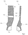
Fig. 2 is a schematic cross-section of a longitudinal member of the system shown inFig. 1 . - Several embodiments of the present invention will be described in more detail below with reference to the accompanying drawings in order for those skilled in the art to be able to carry out the invention. The invention may, however, be embodied in many different forms and should not be construed as limited to the embodiments set forth herein. Rather, these embodiments are provided so that this disclosure will be thorough and complete, and will fully convey the scope of the invention to those skilled in the art. The embodiments do not limit the invention, but the invention is only limited by the appended patent claims. Furthermore, the terminology used in the detailed description of the particular embodiments illustrated in the accompanying drawings is not intended to be limiting of the invention.
- In general, the present invention pertains to a system and devices thereof, for obtaining a dental superstructure, and subsequently a dental prosthesis, comprising said dental superstructure and an appropriate facing material thereon, without any form of screw channel mouth in the masticating surface. The system instead assures that the superstructure may be attached to a dental implant through a tightening screw lingually. In this way a more aesthetic and endurable construction may be obtained.
- According to the embodiment disclosed in
Fig. 1 andFig. 2 , asuperstructure attachment system 100 is disclosed, said system comprising a dentalimplant connecting member 101 and alongitudinal member 102 acting as a superstructure connecting part. Thelongitudinal member 102 comprises two portions, amain member 102a and alever member 102b, which in use are held together by a screw member arranged in a correspondingly threadedscrew hole 103. The twomembers implant connecting part 101, and therefore also distally from the jaw bone to which an implant (not shown) is secured. Thescrew hole 103 extends substantially transversally in respect of the longitudinal extension of the twomembers portion 102a. - The thread of the
screw hole 103 may be such that at least a part of thescrew hole 103a inportion 102a is threaded.Portion 102b may comprise a receivingseat 103b, for receiving the screw member arranged in thescrew hole 103a and protruding from aninterface surface 105a on theportion 102a. In this way, theportion 102a may be pushed away from theportion 102b by screwing the screw member into thescrew hole 103 and pushing onto the receiving seat 104. Theportion 102b may also have a threaded part in the receiving seat 104. In this way the screw member may be prearranged in the screw hole, holdingportion portion 102b may be threaded in the opposite direction to the thread in thescrew hole 103a ofportion 102a. In this way the separation action betweenportion portion screw hole 103. - The
implant connecting member 101 and thelongitudinal member 102 are connected to each other at acurved interface area 106 forming a ball-socket joint. The ball-socket joint is formed by a partially sphericallyshaped protrusion 110 arranged at the distal end of thedental implant member 101, and arecess protrusion 110. - The functionality of the
superstructure attachment system 100 will now be described. The dentalimplant connecting member 101 is tightly attached to the dental implant by ascrew 109 threadably engageable with the dental implant. Themain member 102a and thelever member 102b of thelongitudinal member 102 are fitted to engage with partially spherically shaped distal end of theimplant connecting member 101. As thelever member 102b and themain member 102a are in close contact along their longitudinal axis, thelongitudinal member 102 may be angularly displaced relative the longitudinal axis of theimplant connecting member 101 by means of the ball-socket joint formed at the interface between theimplant connecting member 101 and thelongitudinal member 102. - Then, a superstructure (not shown), with cavities adapted for receiving the
longitudinal member 102, is arranged onto the longitudinal member(s). The cavities of the superstructure are shaped such that the mouth for receiving the longitudinal member comprises a seat for aflange 107 in a proximal zone of thelongitudinal member 102. The cooperation between theflange 107 and the corresponding seat in the superstructure will enhance the leverage of the separation force from separation of themain member 102a and thelever member 102b, since a distinct leverage point will be formed at the interface between the two. - When the superstructure has been slid onto the longitudinal portion and the
longitudinal member 102 consequently is positioned at a desired angle, the screw inserted into thescrew bore 103 of themain member 102a is tightened such that it protrudes outside themain member 102a and consequently causing a relative movement between thelever member 102b and themain member 102a. As a distance between thelever member 102b and themain member 102a is induced, the partially spherically shapedrecess longitudinal member 102 will consequently clamplongitudinal member 102 to theimplant connecting member 101, such that thelongitudinal member 102 is tightly connected to the implant connecting member. - A superstructure may be attached to the
system 100 after the position of thelongitudinal member 102 relative theimplant connecting member 101 has been secured. Preferably, the superstructure comprises at least one interior channel for receiving alongitudinal member 102. More preferably, each one of the interior channels is reachable from the oral cavity by an opening, such that the superstructure may be further attached to thesystem 100 by means of a screw. Hence, the opening is aligned with thescrew hole 103 of themain member 102a of thelongitudinal member 102. - The dental
implant connecting member 101 is preferably a two-part piece, comprising a bolt and a fitting. The bolt has a threadedpart 109 andtool receiving part 108 such that it may be tightly screwed into the implant. Before the bolt is fitted into the implant, it is inserted into the fitting such that the fitting will be secured relative the implant upon tightening of the bolt. For this purpose, the fitting is equipped with aprotrusion 112 and arecess 111 which engage with the implant and/or the bone of the patient for preventing rotational movement of the fitting relative the implant. - The
tool receiving part 108 is formed as a cylindrical or conical recess in the spherically shaped distal end, wherein the longitudinal axis of said recess is aligned with the longitudinal axis of the implant. Hence, the distal end is formed as a sphere integrally formed with the protrusion/recess part - With reference to
Fig. 2 , thelongitudinal member 102 will be described in more detail. Here, thelongitudinal member 102 is formed by themain member 102a and thelever member 102b. When thelever member 102b is in close contact with themain member 102a, the longitudinal member is generally extending in a longitudinal direction and consists of three general parts; a cylindrical part, a flange, and a conical part. The cylindrical part is arranged at the distal end of thelongitudinal member 102 and extends distally from theflange 107. Proximally of saidflange 107, a conical part is arranged. The conical part comprises a proximal recess having a curvature corresponding to the distal end of theimplant connecting member 101. - The
main member 102a and thelever member 102b are facing each other via thesurfaces lever member 102b and themain member 102a. The distal portion of the interface between thesurfaces longitudinal member 102, while the proximal portion of the interface between thesurfaces longitudinal member 102, such that theinterface surface 105a has a normal facing proximally and transversally and theinterface surface 105b faces distally and transversally, with respect to the longitudinal direction of themember 102. In this way, the demounting of the superstructure from theimplant connecting member 101 and thus the implant may be facilitated, since the superstructure may be lifted in the distal direction once the screw member inscrew hole 103 stops to exert pressure on thelever member 102b. In this position the superstructure may be lifted together with themain member 102a, due to the angled arrangement of theinterface surfaces longitudinal member 102. Hence, this arrangement of an at least partially angled interface area facilitates separation of themain member 102a and thelever member 102b by means of reducing the risk of that the members are stuck to each other. In other embodiments the angled interface portion is made longer; e.g., the entire interface area may be angled relative the longitudinal axis of thelongitudinal member 102. The interface area formed by thesurfaces - Preferably, the interface between the
surfaces spherical recess longitudinal member 102. In other embodiments, however, the interface end point could be located slightly off-center. - As shown in
Fig. 2 , the throughhole 103a of themain member 102a is substantially perpendicular to the longitudinal axis of themain member 102a. Thelever member 102b has acorresponding seat 103b for receiving a screw protruding through saidmain member 102a. - In other embodiments, the
screw hole screw hole portions portion 102a having opposite threading direction than the threading direction in the screw hole part corresponding toportion 102b. Analogously, the screw member may have the corresponding threads, such that screwing action on the screw member in thescrew hole 103 will result in increased separation effect. One rotation of the screw member will then result in a separation of theportions - In further embodiments, the threaded
holes hole 103a is directed slightly distally. - The diameter of the
longitudinal member 102 is preferably in the range of 2 to 5 mm, such that it may be accommodated within the oral cavity while still providing sufficient strength and stability to the superstructure. The total length of the longitudinal member is in the range of 10 to 15 mm, and hence the displacement of thelever member 102b relative themain member 102a is sub-millimeter at the most distal end in order to provide sufficient clamping of thelongitudinal member 102 to theimplant connecting member 101. - Although the present invention has been described above with reference to specific embodiments, it is not intended to be limited to the specific form set forth herein. Rather, the invention is limited only by the accompanying claims
Claims (9)
- A dental superstructure connection device (102) in combination with a dental superstructure for attaching said dental superstructure to a dental implant with a spherical implant head or an implant connecting member (101) with a spherical distal portion, said dental superstructure connecting device (102) comprising
a longitudinal member (102) with a spherically shaped recess (104a, 104b) in its proximal end for connection with said implant or implant connecting member (101),
a main member (102a) and a lever member (102b), said main member (102a) comprising a part of said spherically shaped recess (104a) and said lever member (102b) comprising another part of said spherically shaped recess (104b), wherein the longitudinal member (102) further comprises a flange (107) arranged between the proximal end and the distal end of said longitudinal member (102), said superstructure comprising at least one interior channel for receiving the longitudinal member (102), said at least one interior channel comprising a seat for the flange (107),
wherein said dental superstructure connecting device (102) further comprises means (103) for urging said lever member (102b) and said main member (102a) away from each other distally of said spherically shaped recess (104a, 104b), such that said parts of the spherically shaped recess (104a, 104b) are forced towards each other, when said superstructure is slid onto the longitudinal member (102) such that a leverage point is formed by the flange (107) in the seat of the superstructure. - The dental superstructure connecting device according to claim 1, wherein the main member (102a) forms the lingual part of said longitudinal member (102) and a lever member (102b) forms the buccal or labial part of said longitudinal member (102),
- The dental superstructure connection device of claim 1 or 2, wherein the longitudinal member (102) has a circular cross-section.
- The dental superstructure connection device according to any one of claims 1 to 3, wherein a first portion of the longitudinal interface between the main member (102a) and the lever member (102b) is angled relative the longitudinal axis of the longitudinal member (102).
- The dental superstructure connection device according to claim 4, wherein a second portion of the longitudinal interface between the main member (102a) and the lever member (102b) is parallel to the longitudinal axis of the longitudinal member (102).
- The dental superstructure connection device according to any one of claims 1 to 5, wherein each one of said at least one interior channels is reachable from the oral cavity by an opening, and wherein said means (103) for urging said lever member (102b) and said main member (102a) away from each other comprises a screw being inserted into a screw hole (103a) of said main member (102a),and engaging with the threads of said screw hole (103a) such that it protrudes outside the main member (102a) and pushes the lever member (102b) away from said main member (102a), said opening being aligned with said screw hole (103a).
- The dental superstructure connection device according to claim 6 , wherein said lever member (102b) comprises a threaded recess (103b) axially aligned with the screw hole (103a) of the main member (102a), such that said recess (103b) and said screw hole (103a) are configured to receive a screw.
- The dental superstructure connection device according to claim 7, wherein said screw is configured to connect the main member (102a) with the lever member (102b) while at the same time allowing relative movement of the main member (102a) and the lever member (102b).
- The dental superstructure connection device according to claim 8, wherein the threads of the through hole (103a) are of opposite direction than the threads of the recess (103b).
Applications Claiming Priority (2)
| Application Number | Priority Date | Filing Date | Title |
|---|---|---|---|
| SE1150444 | 2011-05-16 | ||
| PCT/EP2012/059154 WO2012156459A1 (en) | 2011-05-16 | 2012-05-16 | Dental superstructure attaching system and methods for attaching a dental superstructure to a dental implant |
Publications (2)
| Publication Number | Publication Date |
|---|---|
| EP2709553A1 EP2709553A1 (en) | 2014-03-26 |
| EP2709553B1 true EP2709553B1 (en) | 2016-08-10 |
Family
ID=46125451
Family Applications (1)
| Application Number | Title | Priority Date | Filing Date |
|---|---|---|---|
| EP12722146.3A Active EP2709553B1 (en) | 2011-05-16 | 2012-05-16 | Dental superstructure attaching system and method for attaching a dental superstructure to a dental implant |
Country Status (11)
| Country | Link |
|---|---|
| US (1) | US10004576B2 (en) |
| EP (1) | EP2709553B1 (en) |
| JP (1) | JP5978537B2 (en) |
| KR (1) | KR101606254B1 (en) |
| CN (1) | CN103732177B (en) |
| AU (1) | AU2012258258B2 (en) |
| BR (1) | BR112013029517A2 (en) |
| CA (1) | CA2834661A1 (en) |
| ES (1) | ES2600408T3 (en) |
| IL (1) | IL229408A0 (en) |
| WO (1) | WO2012156459A1 (en) |
Families Citing this family (3)
| Publication number | Priority date | Publication date | Assignee | Title |
|---|---|---|---|---|
| KR200471489Y1 (en) * | 2012-04-04 | 2014-02-28 | 왕제원 | Freely adjust the angle and position adjustable attachment for fixing dentures |
| ES2753552T3 (en) * | 2014-04-04 | 2020-04-13 | Addbutment Dental Ab | Fixation system for dental implants |
| SE540145C2 (en) * | 2016-07-26 | 2018-04-10 | Addbutment Dental Ab | Fastening system for fastening a dental prosthesis to a dental implant |
Family Cites Families (19)
| Publication number | Priority date | Publication date | Assignee | Title |
|---|---|---|---|---|
| DK233384A (en) * | 1983-05-17 | 1984-11-18 | Alberto Arruga Artal | FIXED DENTAL IMPLANT |
| US4575340A (en) * | 1985-02-04 | 1986-03-11 | Lustig Leopold P | Precision dental restorative system |
| US4753729A (en) | 1985-04-26 | 1988-06-28 | Baxter Travenol Laboratories, Inc. | Rotor drive for medical disposables |
| AT393952B (en) * | 1990-08-01 | 1992-01-10 | Sichler Heimo | THERMALLY ADJUSTABLE AND FIXABLE IMPLANT POST |
| US5106299A (en) * | 1991-06-25 | 1992-04-21 | Ghalili Kambiz M | Dental prosthesis for use with an oral implant, and method of installation |
| JPH06237944A (en) * | 1993-02-12 | 1994-08-30 | Nikon Corp | Member combination for intraoseal implant |
| US5599185A (en) * | 1994-09-28 | 1997-02-04 | Greenberg Surgical Technologies, Llc | Dental implant healing abutment |
| DE9419508U1 (en) * | 1994-12-06 | 1996-04-04 | Unger, Heinz-Dieter, Dr.med.dent., 49080 Osnabrück | Prosthetic superstructure |
| US6287115B1 (en) * | 1998-11-17 | 2001-09-11 | L. Paul Lustig | Dental implant and tool and method for effecting a dental restoration using the same |
| SE516040C2 (en) | 2000-03-23 | 2001-11-12 | Nobel Biocare Ab | Arrangement including spacer for implants and such spacer and screwdriver for spacer attachment |
| US6986660B2 (en) * | 2002-06-04 | 2006-01-17 | Zimmer Dental, Inc. | Retaining screw with rententive feature |
| JP4257184B2 (en) | 2003-03-07 | 2009-04-22 | 株式会社湊川金属テストピース製作所 | Bone expansion device |
| ES2278477B1 (en) * | 2004-07-30 | 2008-06-01 | Esteban Xam-Mar Mangrane | Dynamic pier for correcting implants in bone, has base and shaft so that the base has hemispherical configuration and end of shaft coupled to base has complementary configuration |
| US9844662B2 (en) * | 2005-10-03 | 2017-12-19 | Washington University | System for stimulating bone growth, tissue healing and/or pain control, and method of use |
| US20080033431A1 (en) * | 2006-06-29 | 2008-02-07 | Searete Llc, A Limited Liability Corporation Of The State Of Delaware | Position augmenting mechanism |
| CA2663759C (en) | 2006-10-02 | 2015-07-21 | Adrian Auderset | Anchor for securing a tooth replacement |
| US20080312655A1 (en) * | 2007-06-14 | 2008-12-18 | X-Spine Systems, Inc. | Polyaxial screw system and method having a hinged receiver |
| US20100291507A1 (en) | 2009-05-13 | 2010-11-18 | Custom Spine, Inc. | Polyaxial Dental Implant |
| SE539272C2 (en) * | 2012-07-11 | 2017-06-07 | Heraeus Kulzer Gmbh | Superstructure and methods for manufacturing the same |
-
2012
- 2012-05-16 WO PCT/EP2012/059154 patent/WO2012156459A1/en not_active Ceased
- 2012-05-16 CN CN201280024011.2A patent/CN103732177B/en active Active
- 2012-05-16 CA CA2834661A patent/CA2834661A1/en not_active Abandoned
- 2012-05-16 US US14/117,939 patent/US10004576B2/en active Active
- 2012-05-16 JP JP2014510803A patent/JP5978537B2/en active Active
- 2012-05-16 EP EP12722146.3A patent/EP2709553B1/en active Active
- 2012-05-16 AU AU2012258258A patent/AU2012258258B2/en not_active Ceased
- 2012-05-16 ES ES12722146.3T patent/ES2600408T3/en active Active
- 2012-05-16 KR KR1020137031500A patent/KR101606254B1/en not_active Expired - Fee Related
- 2012-05-16 BR BR112013029517A patent/BR112013029517A2/en not_active IP Right Cessation
-
2013
- 2013-11-12 IL IL229408A patent/IL229408A0/en unknown
Also Published As
| Publication number | Publication date |
|---|---|
| CN103732177A (en) | 2014-04-16 |
| ES2600408T3 (en) | 2017-02-08 |
| KR20140036207A (en) | 2014-03-25 |
| EP2709553A1 (en) | 2014-03-26 |
| CA2834661A1 (en) | 2012-11-22 |
| JP5978537B2 (en) | 2016-08-24 |
| CN103732177B (en) | 2016-12-07 |
| BR112013029517A2 (en) | 2017-01-24 |
| JP2014515957A (en) | 2014-07-07 |
| WO2012156459A1 (en) | 2012-11-22 |
| KR101606254B1 (en) | 2016-04-01 |
| AU2012258258B2 (en) | 2015-05-14 |
| IL229408A0 (en) | 2014-01-30 |
| US20140178837A1 (en) | 2014-06-26 |
| AU2012258258A1 (en) | 2013-11-07 |
| US10004576B2 (en) | 2018-06-26 |
Similar Documents
| Publication | Publication Date | Title |
|---|---|---|
| US11730572B2 (en) | Apparatus for attaching a dental component to a dental implant | |
| KR102673153B1 (en) | Omnidirectional multi-unit abutment system for screw-mounted dental prostheses | |
| EP2684539B1 (en) | Superstructure | |
| US20060127849A1 (en) | Dental implant system | |
| EP2346435B1 (en) | Superstructure for a dental implant | |
| AU2012258258B2 (en) | Dental superstructure attaching system and methods for attaching a dental superstructure to a dental implant | |
| US20190290404A1 (en) | Dental implant system | |
| EP3372190B1 (en) | Unit comprising a dental implant and prosthetic components, including a transepithelial sleeve with an anti-rotational upper connection | |
| EP3490492B1 (en) | Fastening system for fastening a dental prosthesis to a dental implant | |
| LU101149B1 (en) | Tool assembly for mounting of a dental prosthesis an method of mounting | |
| JP2013236855A (en) | Implement for detaching dental abutment from implant fixture |
Legal Events
| Date | Code | Title | Description |
|---|---|---|---|
| PUAI | Public reference made under article 153(3) epc to a published international application that has entered the european phase |
Free format text: ORIGINAL CODE: 0009012 |
|
| 17P | Request for examination filed |
Effective date: 20131031 |
|
| AK | Designated contracting states |
Kind code of ref document: A1 Designated state(s): AL AT BE BG CH CY CZ DE DK EE ES FI FR GB GR HR HU IE IS IT LI LT LU LV MC MK MT NL NO PL PT RO RS SE SI SK SM TR |
|
| DAX | Request for extension of the european patent (deleted) | ||
| RAP1 | Party data changed (applicant data changed or rights of an application transferred) |
Owner name: HERAEUS KULZER NORDIC AB |
|
| 17Q | First examination report despatched |
Effective date: 20141020 |
|
| GRAP | Despatch of communication of intention to grant a patent |
Free format text: ORIGINAL CODE: EPIDOSNIGR1 |
|
| INTG | Intention to grant announced |
Effective date: 20160324 |
|
| GRAS | Grant fee paid |
Free format text: ORIGINAL CODE: EPIDOSNIGR3 |
|
| GRAA | (expected) grant |
Free format text: ORIGINAL CODE: 0009210 |
|
| AK | Designated contracting states |
Kind code of ref document: B1 Designated state(s): AL AT BE BG CH CY CZ DE DK EE ES FI FR GB GR HR HU IE IS IT LI LT LU LV MC MK MT NL NO PL PT RO RS SE SI SK SM TR |
|
| REG | Reference to a national code |
Ref country code: GB Ref legal event code: FG4D |
|
| REG | Reference to a national code |
Ref country code: CH Ref legal event code: EP Ref country code: AT Ref legal event code: REF Ref document number: 818251 Country of ref document: AT Kind code of ref document: T Effective date: 20160815 |
|
| REG | Reference to a national code |
Ref country code: IE Ref legal event code: FG4D |
|
| REG | Reference to a national code |
Ref country code: DE Ref legal event code: R096 Ref document number: 602012021470 Country of ref document: DE |
|
| REG | Reference to a national code |
Ref country code: CH Ref legal event code: NV Representative=s name: ISLER AND PEDRAZZINI AG, CH |
|
| RAP2 | Party data changed (patent owner data changed or rights of a patent transferred) |
Owner name: HERAEUS KULZER GMBH |
|
| REG | Reference to a national code |
Ref country code: SE Ref legal event code: TRGR |
|
| REG | Reference to a national code |
Ref country code: LT Ref legal event code: MG4D |
|
| REG | Reference to a national code |
Ref country code: NL Ref legal event code: MP Effective date: 20160810 |
|
| REG | Reference to a national code |
Ref country code: AT Ref legal event code: MK05 Ref document number: 818251 Country of ref document: AT Kind code of ref document: T Effective date: 20160810 |
|
| PG25 | Lapsed in a contracting state [announced via postgrant information from national office to epo] |
Ref country code: LT Free format text: LAPSE BECAUSE OF FAILURE TO SUBMIT A TRANSLATION OF THE DESCRIPTION OR TO PAY THE FEE WITHIN THE PRESCRIBED TIME-LIMIT Effective date: 20160810 Ref country code: HR Free format text: LAPSE BECAUSE OF FAILURE TO SUBMIT A TRANSLATION OF THE DESCRIPTION OR TO PAY THE FEE WITHIN THE PRESCRIBED TIME-LIMIT Effective date: 20160810 Ref country code: NO Free format text: LAPSE BECAUSE OF FAILURE TO SUBMIT A TRANSLATION OF THE DESCRIPTION OR TO PAY THE FEE WITHIN THE PRESCRIBED TIME-LIMIT Effective date: 20161110 Ref country code: RS Free format text: LAPSE BECAUSE OF FAILURE TO SUBMIT A TRANSLATION OF THE DESCRIPTION OR TO PAY THE FEE WITHIN THE PRESCRIBED TIME-LIMIT Effective date: 20160810 Ref country code: FI Free format text: LAPSE BECAUSE OF FAILURE TO SUBMIT A TRANSLATION OF THE DESCRIPTION OR TO PAY THE FEE WITHIN THE PRESCRIBED TIME-LIMIT Effective date: 20160810 Ref country code: IS Free format text: LAPSE BECAUSE OF FAILURE TO SUBMIT A TRANSLATION OF THE DESCRIPTION OR TO PAY THE FEE WITHIN THE PRESCRIBED TIME-LIMIT Effective date: 20161210 Ref country code: NL Free format text: LAPSE BECAUSE OF FAILURE TO SUBMIT A TRANSLATION OF THE DESCRIPTION OR TO PAY THE FEE WITHIN THE PRESCRIBED TIME-LIMIT Effective date: 20160810 |
|
| REG | Reference to a national code |
Ref country code: ES Ref legal event code: FG2A Ref document number: 2600408 Country of ref document: ES Kind code of ref document: T3 Effective date: 20170208 |
|
| PG25 | Lapsed in a contracting state [announced via postgrant information from national office to epo] |
Ref country code: PT Free format text: LAPSE BECAUSE OF FAILURE TO SUBMIT A TRANSLATION OF THE DESCRIPTION OR TO PAY THE FEE WITHIN THE PRESCRIBED TIME-LIMIT Effective date: 20161212 Ref country code: PL Free format text: LAPSE BECAUSE OF FAILURE TO SUBMIT A TRANSLATION OF THE DESCRIPTION OR TO PAY THE FEE WITHIN THE PRESCRIBED TIME-LIMIT Effective date: 20160810 Ref country code: GR Free format text: LAPSE BECAUSE OF FAILURE TO SUBMIT A TRANSLATION OF THE DESCRIPTION OR TO PAY THE FEE WITHIN THE PRESCRIBED TIME-LIMIT Effective date: 20161111 Ref country code: AT Free format text: LAPSE BECAUSE OF FAILURE TO SUBMIT A TRANSLATION OF THE DESCRIPTION OR TO PAY THE FEE WITHIN THE PRESCRIBED TIME-LIMIT Effective date: 20160810 Ref country code: LV Free format text: LAPSE BECAUSE OF FAILURE TO SUBMIT A TRANSLATION OF THE DESCRIPTION OR TO PAY THE FEE WITHIN THE PRESCRIBED TIME-LIMIT Effective date: 20160810 |
|
| PG25 | Lapsed in a contracting state [announced via postgrant information from national office to epo] |
Ref country code: RO Free format text: LAPSE BECAUSE OF FAILURE TO SUBMIT A TRANSLATION OF THE DESCRIPTION OR TO PAY THE FEE WITHIN THE PRESCRIBED TIME-LIMIT Effective date: 20160810 Ref country code: EE Free format text: LAPSE BECAUSE OF FAILURE TO SUBMIT A TRANSLATION OF THE DESCRIPTION OR TO PAY THE FEE WITHIN THE PRESCRIBED TIME-LIMIT Effective date: 20160810 |
|
| REG | Reference to a national code |
Ref country code: DE Ref legal event code: R097 Ref document number: 602012021470 Country of ref document: DE |
|
| REG | Reference to a national code |
Ref country code: FR Ref legal event code: PLFP Year of fee payment: 6 |
|
| PG25 | Lapsed in a contracting state [announced via postgrant information from national office to epo] |
Ref country code: BE Free format text: LAPSE BECAUSE OF FAILURE TO SUBMIT A TRANSLATION OF THE DESCRIPTION OR TO PAY THE FEE WITHIN THE PRESCRIBED TIME-LIMIT Effective date: 20160810 Ref country code: CZ Free format text: LAPSE BECAUSE OF FAILURE TO SUBMIT A TRANSLATION OF THE DESCRIPTION OR TO PAY THE FEE WITHIN THE PRESCRIBED TIME-LIMIT Effective date: 20160810 Ref country code: DK Free format text: LAPSE BECAUSE OF FAILURE TO SUBMIT A TRANSLATION OF THE DESCRIPTION OR TO PAY THE FEE WITHIN THE PRESCRIBED TIME-LIMIT Effective date: 20160810 Ref country code: BG Free format text: LAPSE BECAUSE OF FAILURE TO SUBMIT A TRANSLATION OF THE DESCRIPTION OR TO PAY THE FEE WITHIN THE PRESCRIBED TIME-LIMIT Effective date: 20161110 Ref country code: SK Free format text: LAPSE BECAUSE OF FAILURE TO SUBMIT A TRANSLATION OF THE DESCRIPTION OR TO PAY THE FEE WITHIN THE PRESCRIBED TIME-LIMIT Effective date: 20160810 Ref country code: SM Free format text: LAPSE BECAUSE OF FAILURE TO SUBMIT A TRANSLATION OF THE DESCRIPTION OR TO PAY THE FEE WITHIN THE PRESCRIBED TIME-LIMIT Effective date: 20160810 |
|
| PLBE | No opposition filed within time limit |
Free format text: ORIGINAL CODE: 0009261 |
|
| STAA | Information on the status of an ep patent application or granted ep patent |
Free format text: STATUS: NO OPPOSITION FILED WITHIN TIME LIMIT |
|
| 26N | No opposition filed |
Effective date: 20170511 |
|
| REG | Reference to a national code |
Ref country code: DE Ref legal event code: R082 Ref document number: 602012021470 Country of ref document: DE Representative=s name: HAFNER & KOHL PATENT- UND RECHTSANWAELTE PARTN, DE Ref country code: DE Ref legal event code: R082 Ref document number: 602012021470 Country of ref document: DE Representative=s name: HAFNER & KOHL PARTMBB, DE Ref country code: DE Ref legal event code: R082 Ref document number: 602012021470 Country of ref document: DE Representative=s name: HAFNER & KOHL, DE Ref country code: DE Ref legal event code: R081 Ref document number: 602012021470 Country of ref document: DE Owner name: KULZER GMBH, DE Free format text: FORMER OWNER: HERAEUS KULZER NORDIC AB, HELSINGBORG, SE Ref country code: DE Ref legal event code: R082 Ref document number: 602012021470 Country of ref document: DE Representative=s name: HAFNER & KOHL PATENTANWALTSKANZLEI RECHTSANWAL, DE |
|
| PG25 | Lapsed in a contracting state [announced via postgrant information from national office to epo] |
Ref country code: LU Free format text: LAPSE BECAUSE OF NON-PAYMENT OF DUE FEES Effective date: 20170531 Ref country code: SI Free format text: LAPSE BECAUSE OF FAILURE TO SUBMIT A TRANSLATION OF THE DESCRIPTION OR TO PAY THE FEE WITHIN THE PRESCRIBED TIME-LIMIT Effective date: 20160810 |
|
| PG25 | Lapsed in a contracting state [announced via postgrant information from national office to epo] |
Ref country code: MC Free format text: LAPSE BECAUSE OF FAILURE TO SUBMIT A TRANSLATION OF THE DESCRIPTION OR TO PAY THE FEE WITHIN THE PRESCRIBED TIME-LIMIT Effective date: 20160810 |
|
| REG | Reference to a national code |
Ref country code: IE Ref legal event code: MM4A |
|
| PG25 | Lapsed in a contracting state [announced via postgrant information from national office to epo] |
Ref country code: LU Free format text: LAPSE BECAUSE OF NON-PAYMENT OF DUE FEES Effective date: 20170516 |
|
| PG25 | Lapsed in a contracting state [announced via postgrant information from national office to epo] |
Ref country code: IE Free format text: LAPSE BECAUSE OF NON-PAYMENT OF DUE FEES Effective date: 20170516 |
|
| REG | Reference to a national code |
Ref country code: FR Ref legal event code: PLFP Year of fee payment: 7 |
|
| PG25 | Lapsed in a contracting state [announced via postgrant information from national office to epo] |
Ref country code: MT Free format text: LAPSE BECAUSE OF NON-PAYMENT OF DUE FEES Effective date: 20170516 |
|
| PG25 | Lapsed in a contracting state [announced via postgrant information from national office to epo] |
Ref country code: AL Free format text: LAPSE BECAUSE OF FAILURE TO SUBMIT A TRANSLATION OF THE DESCRIPTION OR TO PAY THE FEE WITHIN THE PRESCRIBED TIME-LIMIT Effective date: 20160810 |
|
| PG25 | Lapsed in a contracting state [announced via postgrant information from national office to epo] |
Ref country code: HU Free format text: LAPSE BECAUSE OF FAILURE TO SUBMIT A TRANSLATION OF THE DESCRIPTION OR TO PAY THE FEE WITHIN THE PRESCRIBED TIME-LIMIT; INVALID AB INITIO Effective date: 20120516 |
|
| PGFP | Annual fee paid to national office [announced via postgrant information from national office to epo] |
Ref country code: HU Payment date: 20190318 Year of fee payment: 7 |
|
| PGFP | Annual fee paid to national office [announced via postgrant information from national office to epo] |
Ref country code: FR Payment date: 20190523 Year of fee payment: 8 |
|
| REG | Reference to a national code |
Ref country code: GB Ref legal event code: 732E Free format text: REGISTERED BETWEEN 20190808 AND 20190814 |
|
| PG25 | Lapsed in a contracting state [announced via postgrant information from national office to epo] |
Ref country code: CY Free format text: LAPSE BECAUSE OF NON-PAYMENT OF DUE FEES Effective date: 20160810 |
|
| PG25 | Lapsed in a contracting state [announced via postgrant information from national office to epo] |
Ref country code: MK Free format text: LAPSE BECAUSE OF FAILURE TO SUBMIT A TRANSLATION OF THE DESCRIPTION OR TO PAY THE FEE WITHIN THE PRESCRIBED TIME-LIMIT Effective date: 20160810 |
|
| PG25 | Lapsed in a contracting state [announced via postgrant information from national office to epo] |
Ref country code: TR Free format text: LAPSE BECAUSE OF FAILURE TO SUBMIT A TRANSLATION OF THE DESCRIPTION OR TO PAY THE FEE WITHIN THE PRESCRIBED TIME-LIMIT Effective date: 20160810 |
|
| PG25 | Lapsed in a contracting state [announced via postgrant information from national office to epo] |
Ref country code: FR Free format text: LAPSE BECAUSE OF NON-PAYMENT OF DUE FEES Effective date: 20200531 |
|
| REG | Reference to a national code |
Ref country code: ES Ref legal event code: FD2A Effective date: 20211001 |
|
| PG25 | Lapsed in a contracting state [announced via postgrant information from national office to epo] |
Ref country code: ES Free format text: LAPSE BECAUSE OF NON-PAYMENT OF DUE FEES Effective date: 20200517 |
|
| PGFP | Annual fee paid to national office [announced via postgrant information from national office to epo] |
Ref country code: DE Payment date: 20250521 Year of fee payment: 14 |
|
| PGFP | Annual fee paid to national office [announced via postgrant information from national office to epo] |
Ref country code: GB Payment date: 20250521 Year of fee payment: 14 |
|
| PGFP | Annual fee paid to national office [announced via postgrant information from national office to epo] |
Ref country code: IT Payment date: 20250527 Year of fee payment: 14 |
|
| PGFP | Annual fee paid to national office [announced via postgrant information from national office to epo] |
Ref country code: CH Payment date: 20250601 Year of fee payment: 14 |
|
| PGFP | Annual fee paid to national office [announced via postgrant information from national office to epo] |
Ref country code: SE Payment date: 20250521 Year of fee payment: 14 |