EP2709407B1 - Communication system, management device, control method, and program - Google Patents
Communication system, management device, control method, and program Download PDFInfo
- Publication number
- EP2709407B1 EP2709407B1 EP12782406.8A EP12782406A EP2709407B1 EP 2709407 B1 EP2709407 B1 EP 2709407B1 EP 12782406 A EP12782406 A EP 12782406A EP 2709407 B1 EP2709407 B1 EP 2709407B1
- Authority
- EP
- European Patent Office
- Prior art keywords
- access
- packet forwarding
- operation modes
- energy consumption
- management apparatus
- Prior art date
- Legal status (The legal status is an assumption and is not a legal conclusion. Google has not performed a legal analysis and makes no representation as to the accuracy of the status listed.)
- Not-in-force
Links
Images


Classifications
-
- H—ELECTRICITY
- H04—ELECTRIC COMMUNICATION TECHNIQUE
- H04W—WIRELESS COMMUNICATION NETWORKS
- H04W52/00—Power management, e.g. Transmission Power Control [TPC] or power classes
- H04W52/02—Power saving arrangements
- H04W52/0209—Power saving arrangements in terminal devices
-
- H—ELECTRICITY
- H04—ELECTRIC COMMUNICATION TECHNIQUE
- H04W—WIRELESS COMMUNICATION NETWORKS
- H04W52/00—Power management, e.g. Transmission Power Control [TPC] or power classes
- H04W52/02—Power saving arrangements
- H04W52/0203—Power saving arrangements in the radio access network or backbone network of wireless communication networks
- H04W52/0206—Power saving arrangements in the radio access network or backbone network of wireless communication networks in access points, e.g. base stations
-
- H—ELECTRICITY
- H04—ELECTRIC COMMUNICATION TECHNIQUE
- H04W—WIRELESS COMMUNICATION NETWORKS
- H04W16/00—Network planning, e.g. coverage or traffic planning tools; Network deployment, e.g. resource partitioning or cells structures
- H04W16/02—Resource partitioning among network components, e.g. reuse partitioning
- H04W16/06—Hybrid resource partitioning, e.g. channel borrowing
-
- H—ELECTRICITY
- H04—ELECTRIC COMMUNICATION TECHNIQUE
- H04W—WIRELESS COMMUNICATION NETWORKS
- H04W52/00—Power management, e.g. Transmission Power Control [TPC] or power classes
- H04W52/02—Power saving arrangements
- H04W52/0203—Power saving arrangements in the radio access network or backbone network of wireless communication networks
-
- Y—GENERAL TAGGING OF NEW TECHNOLOGICAL DEVELOPMENTS; GENERAL TAGGING OF CROSS-SECTIONAL TECHNOLOGIES SPANNING OVER SEVERAL SECTIONS OF THE IPC; TECHNICAL SUBJECTS COVERED BY FORMER USPC CROSS-REFERENCE ART COLLECTIONS [XRACs] AND DIGESTS
- Y02—TECHNOLOGIES OR APPLICATIONS FOR MITIGATION OR ADAPTATION AGAINST CLIMATE CHANGE
- Y02D—CLIMATE CHANGE MITIGATION TECHNOLOGIES IN INFORMATION AND COMMUNICATION TECHNOLOGIES [ICT], I.E. INFORMATION AND COMMUNICATION TECHNOLOGIES AIMING AT THE REDUCTION OF THEIR OWN ENERGY USE
- Y02D30/00—Reducing energy consumption in communication networks
- Y02D30/70—Reducing energy consumption in communication networks in wireless communication networks
Definitions
- a first management apparatus arranged in the communication system, wherein the first management apparatus is configured to control operation modes relating to energy consumption of the access apparatus(es), and cause the second management apparatus, setting the packet handling rule to the packet forwarding apparatus, to control operation modes relating to energy consumption of the packet forwarding apparatus(es) based on a change of the operation modes relating to the energy consumption of the access apparatus(es).
- the path and action calculation unit 20C serves as a function of calculating a packet forwarding path on the basis of communication node position information managed by the communication node position management unit 20F and topology information managed by the topology management unit 20E. In addition, the path and action calculation unit 20C also serves as a function of determining actions that the packet forwarding apparatuses 21 to 26 are instructed to perform. In addition, when receiving a notification of a mode change of any one of the access apparatuses 11 to 13 from the access apparatus management apparatus 10, the path and action calculation unit 20C serves as means for determining a packet forwarding apparatus(es) that needs to undergo a mode change based on communication node position information managed by the communication node position management unit 20F and topology information managed by the topology management unit 20E. In addition, the path and action calculation unit 20C serves as a means (range determination means) of changing the mode change range of the packet forwarding apparatus(es) (interfaces, etc.) and means for changing modes of the packet forwarding apparatus(es).
- the topology management unit 20E establishes network topology information, based on a connection relationship among the packet forwarding apparatuses 21 to 26 collected via the node communication unit 20A. In addition, when detecting a change in the topology information, the topology management unit 20E notifies the path and action calculation unit 20C of the change.
- the access apparatus 12 is switched to the energy saving mode.
- the step for Energy saving activation if any communication terminal connected to the access apparatus 12 exists, the access apparatus 12 hands over such communication terminal to a neighboring access apparatus.
- the packet forwarding apparatus management apparatus 20 Upon completion of the step for Energy saving activation, the packet forwarding apparatus management apparatus 20 transmits a reply to the request for switching a packet forwarding apparatus(es) to the energy saving mode to the access apparatus management apparatus 10 (S208 in Fig. 5 ).
- the access apparatus management apparatus 10a when determining an access apparatus that needs to undergo a mode change, the access apparatus management apparatus 10a considers the energy amounts of the packet forwarding apparatuses that accordingly change. Thus, it is possible to select an access apparatus and a packet forwarding apparatus with which the maximum energy saving amount can be achieved.
- the access apparatus management apparatus may change the mode of an access apparatus, based on an access apparatus management schedule. For example, the schedule indicates that a certain access apparatus needs to be switched to the energy saving mode from 2:00 a.m. to 7:00 a.m.
- the above exemplary embodiments have been described assuming that all the interfaces included in the packet forwarding apparatuses are wired interfaces. However, alternatively, the interfaces may be wireless interfaces.
- the above exemplary embodiments have been described assuming that the communication nodes are directly connected to the backhaul.
- the communication nodes may be connected to the backhaul via apparatuses (routers, L2 switches, etc.) that are not managed by the packet forwarding apparatus management apparatus.
- the packet forwarding apparatus management apparatus may change the above packet forwarding paths at the time of a mode change. In such case, along with the step for Energy saving (de)activation, processing for updating the packet forwarding rules for communication among communication nodes that do not undergo a mode change may be performed.
- the packet forwarding apparatus management apparatus can determine the range of packet forwarding apparatuses that undergo a mode change.
Landscapes
- Engineering & Computer Science (AREA)
- Computer Networks & Wireless Communication (AREA)
- Signal Processing (AREA)
- Mobile Radio Communication Systems (AREA)
Description
- The present invention relates to a communication system, a management apparatus, a control method, and a program. In particular, it relates to: a communication system including apparatuses capable of changing operation modes relating to energy consumption; a management apparatus; a control method; and a program.
- 3GPP TS 23.401 V10.3.0 "General Packet Radio Service (GPRS) enhancements for Evolved Universal Terrestrial Radio Access Network (E-UTRAN) access," [online], [searched on April 14, 2011], Internet <http://www.3gpp.org/ftp/Specs/html-info/23401.htm> discloses an example of a conventional communication system. As illustrated in
Fig. 9 , thisconventional communication system 1 includes abackhaul 2, an Equipment Management Server for eNodeBs (hereinafter referred to as "an EMS(eNodeB)") 110, E-UTRAN NodeBs (hereinafter referred to as "eNodeBs") 111 to 113, a Mobility Management Entity (hereinafter referred to as "an MME") 130, a Serving Gateway (hereinafter referred to as "a Serving GW") 140, and a Packet Data Network Gateway (hereinafter referred to as "a PDN GW") 150. In addition, thebackhaul 2 includesrouters 121 to 126 and an EMS (hereinafter referred to as "an EMS(BH)) 120 managing these routers. InFig. 9 , lower case letters alphabets attached to the routers are identifiers for identifying corresponding interfaces. In addition, inFig. 9 , some pairs of the components in the conventional system are connected by solid lines while other pairs are connected by dashed lines. The dashed lines indicate wireless connection and the solid lines indicate wired connection. - The EMS(eNodeB) 110 manages the eNodeBs 111 to 113. For example, the EMS(eNodeB) 110 includes: a function of setting eNodeBs when a new eNodeB is installed; a function of monitoring the number of communication terminals connected to each eNodeB or the traffic amount flowing through each eNodeB; a function of managing the coverage area of each eNodeB; and a function of changing an operation mode of an eNodeB (between an energy saving mode (power saving mode) and a non energy saving mode (non-power saving mode)).
- Each of the eNodeBs 111 to 113 is a radio access apparatus for providing communication terminals with connectivity to the
communication system 1 by using a radio access method called Long Term Evolution (LTE). - The EMS(BH) 120 manages the
routers 121 to 126. For example, the EMS(BH) 120 includes a function of setting a newly installed router and a function of changing a path in accordance with traffic change or failure. - Each of the
routers 121 to 126 is a packet forwarding apparatus for performing packet forwarding in accordance with the destination IP address of a received IP packet. - The MME 130 is a control apparatus for performing control operations so that the communication terminals receive mobile services via the eNodeBs. Examples of such control operations include an authentication operation and a handover operation between eNodeBs.
- The Serving GW 140 is an access GW apparatus for providing a bearer serving as a communication path in which communication terminals perform data communication. The Serving GW 140 establishes a packet forwarding tunnel with an eNodeB and the PDN GW.
- The PDN GW 150 is a mobile anchor apparatus terminating a bearer serving as a communication path in which communication terminals perform packet communication. To provide the bearer, the PDN GW 150 establishes a packet forwarding tunnel with the Serving GW.
-
Fig. 10 illustrates an operation in which the EMS(eNodeB) 110 in thecommunication system 1 inFig. 9 detects a traffic decrease and causes theeNodeB 112 to switch to the energy saving mode. While the expression "energy saving mode" is used herein, an operation of entirely or partially stopping power supply to an eNodeB is assumed. For example, power supply to an antenna of an eNodeB is stopped or at least one of a plurality of DSPs (Digital Signal Processors) of an eNodeB is stopped. In addition, dashed lines inFig. 10 indicate operations performed as needed. - In
Fig. 10 , the EMS(eNodeB) 110 regularly acquires information stored by the eNodeBs from the eNodeBs 111 to 113 (S101). The information includes the number of communication terminals connected to each eNodeB, the traffic amount flowing through each eNodeB, and the strengths of radio waves received from neighboring eNodeBs, for example. - After acquiring the above information from the eNodeBs 111 to 113, the EMS(eNodeB) 110 detects a decrease in the traffic amount flowing through the
communication system 1. Next, the EMS(eNodeB) 110 determines which eNodeB needs to be switched to the energy saving mode, based on the coverage area of each eNodeB and the traffic amount flowing through each eNodeB (S102). In this example, the EMS(eNodeB) 110 determines that the eNodeB 112 needs to be switched to the energy saving mode. - Next, to switch the eNodeB 112 to the energy saving mode, the EMS(eNodeB) 110 performs a step for Energy saving activation (S103). If switching the eNodeB 112 to the energy saving mode causes a hole in the coverage area, Energy saving compensation activation may be performed to change the transmission power of the
eNodeBs - If the step for Energy saving activation is performed, the eNodeB 112 is switched to the energy saving mode. When the step for Energy saving activation is performed, if any communication terminal connected to the
eNodeB 112 exists, the eNodeB 112 hands over such communication terminal to a neighboring eNodeB. - Next, based on information acquired from the eNodeBs 111 and 113 (S105), the EMS(eNodeB) 110 detects an increase in the traffic amount flowing through the
communication system 1. Next, the EMS(eNodeB) 110 determines that the energy-saving eNodeB 112 needs to be switched back to the non energy saving mode (S106). - Next, the EMS(eNodeB) 110 performs a step for Energy saving deactivation, to switch the eNodeB 112 back to the non energy saving mode (S107). When the eNodeB 112 is switched to the energy saving mode, if Energy saving compensation activation is being performed, Energy saving compensation deactivation is performed to set the transmission power of the
eNodeBs eNodeB 112, back to the respective normal levels (S108). - The first problem with the above background art is that energy is wastefully consumed by a apparatus(es) in the backhaul. This is because control of the eNodeBs and control of the backhaul are not coordinated. Namely, if an eNodeB is switched to the energy saving mode, a packet forwarding apparatus such as a router that has been providing the eNodeB with connectivity is not temporarily used. However, according to the above background art, such packet forwarding apparatus consumes the same amount of energy as it does when used.
-
EP2244508 discusses a method for activating a power save mode in a first network comprising a femtocell.US 2010/284287 discloses access and packet forwarding apparatus of a telecommunication network. However the operation modes of the routing apparatuses is not changed based on the power operation mode of the access devices. - We have appreciated that it would be desirable to provide a communication system, a management apparatus, a control method, and a program capable of preventing excess energy consumption within a backhaul.
- According to a first aspect of the present invention, there is provided a communication system, comprising: an access apparatus(es) accessed by communication terminals; a packet forwarding apparatus(es) forwarding packets according to a packet handling rule via the access apparatus(es); a first management apparatus controlling operation modes relating to energy consumption of the access apparatus(es); and a second management apparatus setting the packet handling rule to the packet forwarding apparatus(es), controlling operation modes relating to energy consumption of the packet forwarding apparatus(es) based on a change of the operation modes relating to the energy consumption of the access apparatus(es).
- According to a second aspect of the present invention, there is provided a first management apparatus arranged in the communication system, wherein the first management apparatus is configured to control operation modes relating to energy consumption of the access apparatus(es), and cause the second management apparatus, setting the packet handling rule to the packet forwarding apparatus, to control operation modes relating to energy consumption of the packet forwarding apparatus(es) based on a change of the operation modes relating to the energy consumption of the access apparatus(es). With this configuration, energy saving of the packet forwarding apparatus(es) can be controlled in conjunction with energy saving of the access apparatus(es).
- According to a third aspect of the present invention, there is provided a second management apparatus, arranged in the communication system, wherein the second management apparatus is configured to control operation modes relating to energy consumption of the access apparatus(es), and controlling operation modes relating to energy consumption of the packet forwarding apparatus(es) based on a change of the operation modes relating to the energy consumption of the access apparatus.
- According to a fourth aspect of the present invention, there is provided a control method of operation modes of an access apparatus(es) accessed by communication terminals and of a packet forwarding apparatus(es) forwarding packets according to a packet handling rule via the access apparatus(es) included in a communication system, the control method comprising steps of: controlling operation modes relating to energy consumption of the access apparatus(es); and controlling operation modes relating to energy consumption of the packet forwarding apparatus(es) based on a change of the operation modes relating to the energy consumption of the access apparatus(es). This method is associated with certain machines, namely, with management apparatus controlling the access apparatus(es) and the packet forwarding apparatus(es) in the communication system.
- According to a fifth aspect of the present invention, there is provided a program, causing a computer managing an access apparatus(es) accessed by communication terminals and a packet forwarding apparatus(es) forwarding packets according to a packet handling rule via the access apparatus(es) included in a communication system to execute processes of: controlling operation modes relating to energy consumption of the access apparatus(es); and controlling operation modes relating to energy consumption of the packet forwarding apparatus(es) based on a change of the operation modes relating to the energy consumption of the access apparatus(es). This program can be recorded in a computer-readable storage medium. Namely, the present invention can be embodied as a computer program product.
- According to the present invention, excess energy consumption within a backhaul can be prevented.
-
-
Fig. 1 illustrates an outline of the present invention. -
Fig. 2 is a block diagram illustrating a configuration according to a first exemplary embodiment of the present invention. -
Fig. 3 is a block diagram illustrating a configuration of an access apparatus management apparatus according to the first exemplary embodiment of the present invention. -
Fig. 4 is a block diagram illustrating a configuration of a packet forwarding apparatus management apparatus according to the first exemplary embodiment of the present invention. -
Fig. 5 is a sequence diagram illustrating an operation according to the first exemplary embodiment of the present invention. -
Fig. 6 is a sequence diagram that followsFig. 5 . -
Fig. 7 is a block diagram illustrating a configuration according to a second exemplary embodiment of the present invention. -
Fig. 8 is a sequence diagram illustrating an operation according to the second exemplary embodiment of the present invention. -
Fig. 9 is a block diagram illustrating a configuration of a communication system described in the Background section. -
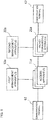
Fig. 10 is a sequence diagram illustrating an operation of the communication system described in the Background section. - First, an outline of an exemplary embodiment of the present invention will be described with reference to a drawing. In the following outline, various components are denoted by reference characters for the sake of convenience. Namely, the following reference characters are merely used as examples to facilitate understanding of the present invention. Thus, the present invention is not limited to the illustrated examples. As illustrated in
Fig. 1 , an exemplary embodiment of the present invention can be realized by a configuration including at least oneaccess apparatus 11a accessed bycommunication terminals 61, at least onepacket forwarding apparatus 21a forwarding packets via theaccess apparatus 11a, afirst management apparatus 10a, and asecond management apparatus 20a. - More specifically, the
first management apparatus 10a controls operation modes relating to energy consumption of theaccess apparatus 11a, based on a state thereof. Examples of the state include the number ofcommunication terminals 61 connected to theaccess apparatus 11a, the traffic amount flowing through theaccess apparatus 11a, or the strengths of radio waves received from neighboring access apparatuses. - The
second management apparatus 20a controls operation modes relating to energy consumption of thepacket forwarding apparatus 21a, based on a change detected by thefirst management apparatus 10a in the operation modes relating to energy consumption of theaccess apparatus 11a. - For example, when an
access apparatus 11a is switched to an energy saving state, thesecond management apparatus 20a switches the operation mode of apacket forwarding apparatus 21a, which has been providing thisaccess apparatus 11a with connectivity, from a non energy saving state to an energy saving state. - In this way, as compared with the case where only a
single access apparatus 11a is switched to the energy saving state, the present invention can save more energy consumption by the amount of energy saved by thepacket forwarding apparatus 21a. - Next, a first exemplary embodiment of the present invention will be described in detail with reference to the drawings.
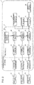
Fig. 2 is a block diagram illustrating a configuration according to the first exemplary embodiment of the present invention.Fig. 2 illustrates a configuration of acommunication system 1 for providingcommunication terminals 61 to 63 with services. InFig. 2 , some pairs of the components according to the present exemplary embodiment are connected by solid lines while other pairs are connected by dashed lines. The dashed lines indicate wireless connection and the solid lines indicate wired connection. - The
communication system 1 includes abackhaul 2, an accessapparatus management apparatus 10,access apparatuses 11 to 13, an access gateway (C-plane) (hereinafter referred to as "an access GW(C-plane)") 30, an access gateway (U-plane) (hereinafter referred to as "an access GW(U-plane)") 40, and amobile anchor apparatus 50. - In addition, the
backhaul 2 includes a packet forwardingapparatus management apparatus 20 andpacket forwarding apparatuses 21 to 26. InFig. 2 , lower case letters in English attached to the packet forwarding apparatuses are identifiers for identifying corresponding interfaces. - The access apparatuses 11 to 13 are apparatuses for providing the
communication terminals 61 to 63 with connectivity to thecommunication system 1 by using a radio access method. Each of theaccess apparatuses 11 to 13 can be realized by a configuration equivalent to that of an eNodeB in "General Packet Radio Service (GPRS) enhancements for Evolved Universal Terrestrial Radio Access Network (E-UTRAN) access,". - When any one of the
packet forwarding apparatuses 21 to 26 receives a packet, that packet forwarding apparatus searches a packet forwarding rule table storing packet forwarding rules for a packet forwarding rule having a matching key matching the received packet and processes the packet in accordance with an action associated with the packet forwarding rule (for example, forwarding to a certain port, flooding, discarding, etc.). Each of thepacket forwarding apparatuses 21 to 26 can be realized by a configuration equivalent to that of an OpenFlow switch in "OpenFlow Switch Specification" Version 1.0.0. (Wire Protocol 0x01), [online], [searched on April 14, 2011], Internet <URL:http://www.openflowswitch.org/documents/openflow-spec-v1.0.0.pdf>. - The access GW(C-plane) 30 is a control apparatus for performing control operations so that the
communication terminals 61 to 63 receive mobile services via theaccess apparatuses 11 to 13. Examples of such control operations include an authentication operation and a handover operation between access apparatuses. The access GW(C-plane) 30 can be realized by a configuration equivalent to that of the MME in "General Packet Radio Service (GPRS) enhancements for Evolved Universal Terrestrial Radio Access Network (E-UTRAN) access,". - The access GW(U-plane) 40 provides a bearer serving as a communication path in which communication terminals perform data communication. To provide the bearer, the access GW(U-plane) 40 establishes a packet forwarding tunnel with the
access apparatuses 11 to 13 and themobile anchor apparatus 50. The access GW(U-plane) 40 can be realized by a configuration equivalent to that of the Serving GW in "General Packet Radio Service (GPRS) enhancements for Evolved Universal Terrestrial Radio Access Network (E-UTRAN) access,". - The
mobile anchor apparatus 50 is a mobile anchor for terminating a bearer serving as a communication path in which communication terminals perform packet communication. To provide the bearer, themobile anchor apparatus 50 establishes a packet forwarding tunnel with the access GW(U-plane) 40. Themobile anchor apparatus 50 can be realized by a configuration equivalent to that of the PDN GW in "General Packet Radio Service (GPRS) enhancements for Evolved Universal Terrestrial Radio Access Network (E-UTRAN) access,". - The access
apparatus management apparatus 10 manages theaccess apparatuses 11 to 13 and corresponds to the abovefirst management apparatus 10a. -
Fig. 3 illustrates a detailed configuration of the accessapparatus management apparatus 10. InFig. 3 , the accessapparatus management apparatus 10 includes an accessapparatus setting unit 10A, an accessapparatus monitoring unit 10B, a coveragearea management unit 10C, an access apparatus management database (a database will hereinafter be referred to as "a DB") 10D, amonitoring information DB 10E, acoverage area DB 10F, and anode communication unit 10G communicating with theaccess apparatuses 11 to 13. - The access
apparatus setting unit 10A is a processing block that sets access apparatuses when a new access apparatus is installed or when operation modes of an access apparatus is changed (between an energy saving mode and a non energy saving mode). Hereinafter, change of the operation modes will simply be referred to as "a mode change." In addition, the accessapparatus setting unit 10A registers content set in the access apparatuses in the accessapparatus management DB 10D. In addition, when an access apparatus undergoes a mode change, the accessapparatus setting unit 10A notifies the packet forwardingapparatus management apparatus 20 of an identifier of the access apparatus. In the present exemplary embodiment, as the identifier of such access apparatus, a MAC address of the access apparatus is used. However, a different identifier may be used. For example, an IP address, a manufacturing number, or the like may be used as the identifier. - In addition, the names of "energy saving mode" and "non energy saving mode" do not need to be used explicitly. The present invention is applicable as long as the communication system uses a normal operation mode and a second operation mode in which reduction in energy consumption is achieved by stopping certain processing or a certain function.
- The access
apparatus monitoring unit 10B is a processing block for monitoring the number of communication terminals connected to each of theaccess apparatuses 11 to 13 or the traffic amounts flowing through each of theaccess apparatuses 11 to 13, for example. In addition, the accessapparatus monitoring unit 10B registers the acquired monitoring information about theaccess apparatuses 11 to 13 in themonitoring information DB 10E. - The coverage
area management unit 10C is a processing block for re-calculating an area coverage structure in response to addition/deletion of an access apparatus or to change in a surrounding environment and for determining the transmission radio wave of or use frequency of each access apparatus. In addition, the coveragearea management unit 10C functions with the accessapparatus monitoring unit 10B and regularly acquires, for example, the number of communication terminals connected to each access apparatus and the traffic amount flowing through each access apparatuses. If the coveragearea management unit 10C detects a large change of the traffic amount in thecommunication system 1, the coveragearea management unit 10C calculates an area coverage structure that can accommodate the current traffic amount and determines an access apparatus that needs to undergo a mode change (between the energy saving mode and the non energy saving mode). - The access
apparatus management DB 10D manages information about settings and positions of the access apparatuses. - The
monitoring information DB 10E manages the monitoring information acquired from theaccess apparatuses 11 to 13. - The
coverage area DB 10F manages information about coverage areas and stores a radio wave coverage status per area. - The above access
apparatus management apparatus 10 can be realized by adding a function of notifying the packet forwardingapparatus management apparatus 20 of an identifier of an access apparatus that needs to undergo a mode change to an Equipment Management Server (EMS) or a Self Organizing Network (SON) server for access apparatuses such as eNodeBs. - The packet forwarding
apparatus management apparatus 20 manages thepacket forwarding apparatuses 21 to 26 and corresponds to the abovesecond management apparatus 20a. -
Fig. 4 illustrates a detailed configuration of the packet forwardingapparatus management apparatus 20. InFig. 4 , the packet forwardingapparatus management apparatus 20 includes anode communication unit 20A communicating with thepacket forwarding apparatuses 21 to 26, a controlmessage processing unit 20B, a path andaction calculation unit 20C, a packet forwardingapparatus management unit 20D, atopology management unit 20E, a communication nodeposition management unit 20F, and a packet forwardingrule management unit 20G. These components operate as follows. - The control
message processing unit 20B analyzes control messages received from thepacket forwarding apparatuses 21 to 26 and transmits information about the control messages to corresponding processing means in the packet forwardingapparatus management apparatus 20. - The path and
action calculation unit 20C serves as a function of calculating a packet forwarding path on the basis of communication node position information managed by the communication nodeposition management unit 20F and topology information managed by thetopology management unit 20E. In addition, the path andaction calculation unit 20C also serves as a function of determining actions that thepacket forwarding apparatuses 21 to 26 are instructed to perform. In addition, when receiving a notification of a mode change of any one of theaccess apparatuses 11 to 13 from the accessapparatus management apparatus 10, the path andaction calculation unit 20C serves as means for determining a packet forwarding apparatus(es) that needs to undergo a mode change based on communication node position information managed by the communication nodeposition management unit 20F and topology information managed by thetopology management unit 20E. In addition, the path andaction calculation unit 20C serves as a means (range determination means) of changing the mode change range of the packet forwarding apparatus(es) (interfaces, etc.) and means for changing modes of the packet forwarding apparatus(es). - The packet forwarding
apparatus management unit 20D manages capabilities (for example, the number of ports, the types of the ports, and the types of supported actions) of thepacket forwarding apparatuses 21 to 26 controlled by the packet forwardingapparatus management apparatus 20. - The
topology management unit 20E establishes network topology information, based on a connection relationship among thepacket forwarding apparatuses 21 to 26 collected via thenode communication unit 20A. In addition, when detecting a change in the topology information, thetopology management unit 20E notifies the path andaction calculation unit 20C of the change. - The communication node
position management unit 20F manages information for determining the positions of the communication nodes connected to the communication system. In the present exemplary embodiment, a MAC address is used as information for identifying a communication node. In addition, information for identifying a packet forwarding apparatus to which the communication node is connected and information about a corresponding port of the packet forwarding apparatus is used as information for determining the position of the communication node. However, alternatively, other information may be used. The "communication node" according to the present exemplary embodiment corresponds to the accessapparatus management apparatus 10, each of theaccess apparatuses 11 to 13, the access GW function (C-plane) 30, the access GW function (U-plane) 40, etc. - The packet forwarding
rule management unit 20G manages packet forwarding rules set in the packet forwarding apparatuses. More specifically, the packet forwardingrule management unit 20G stores results calculated by the path andaction calculation unit 20C, as packet forwarding rules. When notified by any one of thepacket forwarding apparatuses 21 to 26 of deletion of a packet forwarding rule, that is, when a packet forwarding rule set in the packet forwarding apparatus is changed, the packet forwardingrule management unit 20G updates the packet forwarding rule information stored therein. - The packet forwarding
apparatus management apparatus 20 can be realized by adding means for determining a packet forwarding apparatus(es) that needs to undergo a mode change, means for determining the mode change range (interface, etc.) of the packet forwarding apparatus(es), and means for changing the mode of the packet forwarding apparatus(es) to the path andaction calculation unit 20C, on the basis of the OpenFlow controller in the "OpenFlow Switch Specification". - In addition, each processing block of the access
apparatus management apparatus 10 and the packet forwardingapparatus management apparatus 20 illustrated inFigs. 3 and4 can be realized by a computer program causing a computer included in a corresponding one of the apparatuses to use its hardware and to execute each of the above corresponding processing. - Next, an overall operation according to the present exemplary embodiment will be described in detail with reference to the drawings.
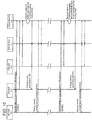
Figs. 5 and6 are sequence diagrams illustrating operations according to the first exemplary embodiment of the present invention.Fig. 5 illustrates an operation of energy saving of an access apparatus and packet forwarding apparatuses performed when the traffic amount flowing through thecommunication system 1 is decreased. In addition, each dashed line with arrows inFig. 5 indicates a step performed as needed. - As illustrated in
Fig. 5 , the accessapparatus management apparatus 10 regularly acquires information (management information) stored in the access apparatuses from theaccess apparatuses 11 to 13 (S201 inFig. 5 ). The information includes the number of communication terminals connected to each access apparatus, the traffic amount flowing through each access apparatus, and the strengths of radio waves received from neighboring access apparatuses, for example. - When acquiring the information from the
access apparatuses 11 to 13, the accessapparatus management apparatus 10 detects a decrease in the traffic amount flowing through thecommunication system 1. Next, based on the coverage area of each of theaccess apparatuses 11 to 13 and the traffic amount flowing through each of theaccess apparatuses 11 to 13, the accessapparatus management apparatus 10 determines an access apparatus that needs to be switched to the energy saving mode (S202 inFig. 5 ). This following description will be made assuming that the accessapparatus management apparatus 10 determines that theaccess apparatus 12 needs to be switched to the energy saving mode. - Next, to switch the
access apparatus 12 to the energy saving mode, the accessapparatus management apparatus 10 performs a step for Energy saving activation (S203 inFig. 5 ). In this step, if switching of theaccess apparatus 12 to the energy saving mode causes a hole in the coverage area, Energy saving compensation activation may be performed to change the transmission power of theaccess apparatuses Fig. 5 ). - If the step for Energy saving activation is performed, the
access apparatus 12 is switched to the energy saving mode. When the step for Energy saving activation is performed, if any communication terminal connected to theaccess apparatus 12 exists, theaccess apparatus 12 hands over such communication terminal to a neighboring access apparatus. - Next, the access
apparatus management apparatus 10 transmits a request for switching a packet forwarding apparatus(es) to the energy saving mode to the packet forwarding apparatus management apparatus 20 (S205 inFig. 5 ). This request for switching a packet forwarding apparatus(es) to the energy saving mode includes the MAC address of theaccess apparatus 12, which is an identifier of the access apparatus. - When receiving the request for switching a packet forwarding apparatus(es) to the energy saving mode, first, the packet forwarding
apparatus management apparatus 20 determines the connection position of the energy-savingaccess apparatus 12, based on the MAC address of theaccess apparatus 12 included in the request for switching a packet forwarding apparatus(es) to the energy saving mode and the position information managed by the communication nodeposition management unit 20F. Next, based on the topology information managed by thetopology management unit 20E and the packet forwarding rule information managed by the packet forwardingrule management unit 20G, the packet forwardingapparatus management apparatus 20 determines a packet forwarding apparatus(es) that can be switched to the energy saving mode when theaccess apparatus 12 stops communication and the range of energy saving (S206 inFig. 5 ). - From the configuration in
Fig. 2 , it is seen that the entirepacket forwarding apparatus 22 and the interface a of thepacket forwarding apparatus 25 can be switched to the energy saving mode when theaccess apparatus 12 is switched to the energy saving mode. Next, to switch thepacket forwarding apparatuses apparatus management apparatus 20 performs a step for Energy saving activation (S207 inFig. 5 ). If the step for Energy saving activation is performed, thepacket forwarding apparatus 22 and the interface a of thepacket forwarding apparatus 25 are switched to the energy saving mode. - Upon completion of the step for Energy saving activation, the packet forwarding
apparatus management apparatus 20 transmits a reply to the request for switching a packet forwarding apparatus(es) to the energy saving mode to the access apparatus management apparatus 10 (S208 inFig. 5 ). -
Fig. 6 illustrates an operation of switching the access apparatus and packet forwarding apparatuses, which have been in the energy saving mode in accordance with the operation inFig. 5 , back to the non energy saving mode, when the traffic amount flowing into thecommunication system 1 is increased. In addition, each dashed line with arrows inFig. 6 indicates a procedure performed as needed. - As illustrated in
Fig. 6 , the accessapparatus management apparatus 10 regularly acquires information stored in the access apparatuses from theaccess apparatuses 11 and 13 (S301 inFig. 6 ). The information includes the number of communication terminals connected to each access apparatus, the traffic amount flowing through each access apparatus, and the strengths of radio waves received from neighboring access apparatuses, for example. - When receiving the information from the
access apparatuses apparatus management apparatus 10 detects an increase in the traffic amount flowing through thecommunication system 1. From the traffic amount flowing through the coverage area of each access apparatus, the accessapparatus management apparatus 10 determines an access apparatus that needs to be switched to the non energy saving mode (S302 inFig. 6 ). The following description will be made assuming that the accessapparatus management apparatus 10 determines that theaccess apparatus 12 needs to be switched to the non energy saving mode. - Next, to enable communication with the
access apparatus 12, the accessapparatus management apparatus 10 transmits a request for switching a packet forwarding apparatus(es) to the non energy saving mode to the packet forwarding apparatus management apparatus 20 (S303 inFig. 6 ). The request for switching a packet forwarding apparatus(es) to the non energy saving mode includes the MAC address of theaccess apparatus 12, which is an identifier of the access apparatus. - When receiving the request for switching a packet forwarding apparatus(es) to the non energy saving mode, the packet forwarding
apparatus management apparatus 20 determines the connection position of theaccess apparatus 12, which is to be switched to the non energy saving mode, based on the MAC address of theaccess apparatus 12 included in the request for switching a packet forwarding apparatus(es) to the non energy saving mode and the position information managed by the communication nodeposition management unit 20F. Next, based on the topology information managed by thetopology management unit 20E and the packet forwarding rule information managed by the packet forwardingrule management unit 20G, the packet forwardingapparatus management apparatus 20 determines a packet forwarding apparatus(es) that needs to be switched to the non energy saving mode when theaccess apparatus 12 starts communication and the range of non energy saving (S304 inFig. 6 ). - From the configuration in
Fig. 2 , it is seen that the entirepacket forwarding apparatus 22 and the interface a of thepacket forwarding apparatus 25 need to be switched to the non energy saving mode when theaccess apparatus 12 is returned to the non energy saving mode from the energy saving mode. Next, to switch thepacket forwarding apparatuses apparatus management apparatus 20 performs a step for Energy saving deactivation (S305 inFig. 6 ). If the step for Energy saving deactivation is performed, thepacket forwarding apparatuses 22 and the interface a of thepacket forwarding apparatus 25 are switched to the non energy saving mode. - Upon completion of the step for Energy saving deactivation, the packet forwarding
apparatus management apparatus 20 transmits a reply to the request for switching a packet forwarding apparatus(es) to the non energy saving mode to the access apparatus management apparatus 10 (S306 inFig. 6 ). - When receiving the reply to the request for switching a packet forwarding apparatus(es) to the non energy saving mode, the access
apparatus management apparatus 10 performs the step for Energy saving deactivation to switch theaccess apparatus 12 to the non energy saving mode (S307 inFig. 6 ). When switching theaccess apparatus 12 to the non energy saving mode, if transmission power of theaccess apparatuses Fig. 6 ). - Thus, according to the present exemplary embodiment, when the mode of an access apparatus is changed, the mode of a packet forwarding apparatus(es) is also changed. In this way, as compared with the case where only a single access apparatus undergoes a mode change, more energy amount can be saved.
- In the present exemplary embodiment, the packet forwarding
apparatus management apparatus 20 uses, as information for determining the position of a communication node, information for identifying a packet forwarding apparatus to which the communication node is connected and information about a corresponding port of the packet forwarding apparatus. With the configuration inFig. 2 , a single packet forwarding apparatus is connected to a single interface of a packet forwarding apparatus. However, alternatively, a plurality of packet forwarding apparatuses may be connected to a single interface of a packet forwarding apparatus via a hub or the like. In such case, too, the packet forwardingapparatus management apparatus 20 can accurately grasp the connected packet forwarding apparatuses. In addition, even if one of the plurality of packet forwarding apparatuses connected to a single interface of a certain packet forwarding apparatus is switched to the energy saving mode, the packet forwardingapparatus management apparatus 20 does not erroneously switch the interface of the certain packet forwarding apparatus to the energy saving mode. - Next, a second exemplary embodiment of the present invention will be described in detail with reference to the drawings. In the second exemplary embodiment, the access apparatus management apparatus is changed.
Fig. 7 is a block diagram illustrating a configuration according to the second exemplary embodiment of the present invention. The second exemplary embodiment differs from the first exemplary embodiment illustrated inFig. 2 in that apacket forwarding apparatus 27 is added between thepacket forwarding apparatuses apparatus management apparatus 10 and the packet forwardingapparatus management apparatus 20 are replaced by an accessapparatus management apparatus 10a and a packet forwardingapparatus management apparatus 20a, respectively. The following description will be made with a focus on the difference from the first exemplary embodiment. - The access
apparatus management apparatus 10a manages theaccess apparatuses 11 to 13. Since basic functions of the accessapparatus management apparatus 10a are similar to those according to the first exemplary embodiment, detailed description thereof will be omitted. However, the accessapparatus management apparatus 10a considers the energy amount of a packet forwarding function(s) that changes in conjunction with an access apparatus that needs to undergo a mode change. - The above access
apparatus management apparatus 10 can be realized by adding means for determining an access apparatus that undergoes a mode change relating to energy consumption in view of the energy amount of a transporting apparatus(es) that changes in conjunction to an Equipment Management Server (EMS) or a Self Organizing Network (SON) server for access apparatuses such as eNodeBs. - In addition, the packet forwarding
apparatus management apparatus 20a according to the present exemplary embodiment is realized by adding a function of replying to a request for switching a packet forwarding apparatus(es) to the energy saving mode from the accessapparatus management apparatus 10a to the packet forwardingapparatus management apparatus 20 according to the above first exemplary embodiment. Since other entities are the same as those of according to the first exemplary embodiment, description thereof will be omitted. - Next, an operation according to the present exemplary embodiment will be described in detail with reference to the drawings.
Fig. 8 is a sequence diagram illustrating an operation according to the second exemplary embodiment of the present invention. As inFig. 5 ,Fig. 8 illustrates an operation of energy saving of an access apparatus and packet forwarding apparatuses performed when the traffic amount flowing into thecommunication system 1 is decreased. - As illustrated in
Fig. 8 , when acquiring the information from theaccess apparatuses 11 to 13 (S401 inFig. 8 ), the accessapparatus management apparatus 10a detects a decrease in the traffic amount flowing through thecommunication system 1. Next, to grasp the energy amounts that can be saved by the respective packet forwarding apparatuses when each of theaccess apparatuses 11 to 13 is switched to the energy saving mode, the accessapparatus management apparatus 10a transmits a request for determining the energy amounts saved by the respective packet forwarding apparatuses to the packet forwardingapparatus management apparatus 20a (402 inFig. 8 ). - When receiving the request for determining the energy amounts saved by the respective packet forwarding apparatuses, the packet forwarding
apparatus management apparatus 20a calculates the energy amounts saved by the respective packet forwarding apparatuses when each one of theaccess apparatuses 11 to 13 is switched to the energy saving mode. For example, with the configuration inFig. 7 , if theaccess apparatus 11 or theaccess apparatus 13 are switched to the energy saving mode, the packet forwardingapparatus management apparatus 20a determines that energy saving can be achieved by a single packet forwarding apparatus (21 or 23) and a single interface (the interface a of thepacket forwarding apparatus 24 or the interface a of the packet forwarding apparatus 26). In contrast, with the configuration inFig. 8 , if theaccess apparatus 12 is switched to the energy saving mode, the packet forwardingapparatus management apparatus 20a determines that energy saving can be achieved by two packet forwarding apparatuses (22 and 27) and a single interface (25a). Next, the packet forwardingapparatus management apparatus 20a transmits a reply to the request for determining the energy amounts saved by the respective packet forwarding apparatuses, the reply including the above calculation results, to the accessapparatus management apparatus 10a (S403 inFig. 8 ). - When receiving the reply to the request for determining the energy amounts saved by the respective packet forwarding apparatuses, the access
apparatus management apparatus 10a determines an access apparatus that needs to be switched to the energy saving mode, in view of the coverage area and the traffic amount flowing through each access apparatus, the energy amounts that can accordingly be saved by the respective packet forwarding apparatuses, and the increased energy amounts of neighboring access apparatuses. The following description will be made assuming that the accessapparatus management apparatus 10a determines that theaccess apparatus 12 needs to be switched to the energy saving mode. - Since the subsequent procedures are the same as those according to the first exemplary embodiment, description thereof will be omitted.
- As described above, according to the present exemplary embodiment, in addition to the above advantageous effects according to the first exemplary embodiment, when determining an access apparatus that needs to undergo a mode change, the access
apparatus management apparatus 10a considers the energy amounts of the packet forwarding apparatuses that accordingly change. Thus, it is possible to select an access apparatus and a packet forwarding apparatus with which the maximum energy saving amount can be achieved. - While exemplary embodiments of the present invention have thus been described, the present invention is not limited thereto. Further variation, substitutions, or adjustments can be made without departing from the basic technical concept of the present invention. For example, the above exemplary embodiments have been described assuming that the access apparatus management apparatus 10(10a) and the packet forwarding apparatus management apparatus 20(20a) are arranged separately. However, alternatively, these apparatuses may be integrated as needed.
- In addition, the above exemplary embodiments have been described assuming that the mode of an access apparatus is changed in view of a state thereof such as a traffic amount flowing therethrough. However, alternatively, a different condition may be used to determine whether to change the mode of an access apparatus. For example, the access apparatus management apparatus may change the mode of an access apparatus, based on an access apparatus management schedule. For example, the schedule indicates that a certain access apparatus needs to be switched to the energy saving mode from 2:00 a.m. to 7:00 a.m.
- In addition, the above exemplary embodiments have been described assuming that all the interfaces included in the packet forwarding apparatuses are wired interfaces. However, alternatively, the interfaces may be wireless interfaces.
- In addition, the above exemplary embodiments have been described assuming that the communication nodes are directly connected to the backhaul. However, alternatively, the communication nodes may be connected to the backhaul via apparatuses (routers, L2 switches, etc.) that are not managed by the packet forwarding apparatus management apparatus.
- In addition, the above exemplary embodiments have been described assuming that, when the mode of a packet forwarding apparatus is changed, packet forwarding rules of the packet forwarding apparatus are always maintained. However, alternatively, when the packet forwarding apparatus is switched to the energy saving mode, the packet forwarding apparatus management apparatus may control the packet forwarding apparatus to release the packet forwarding rules. In such case, along with the step for Energy saving (de)activation of a packet forwarding apparatus, processing for updating the packet forwarding rules may be performed.
- In addition, the above exemplary embodiments have been described assuming that, when a packet forwarding apparatus undergoes a mode change, packet forwarding paths for communication relating to communication nodes that do not undergo a mode change are maintained. However, alternatively, to switch as many packet forwarding apparatuses as possible to the energy saving mode, the packet forwarding apparatus management apparatus may change the above packet forwarding paths at the time of a mode change. In such case, along with the step for Energy saving (de)activation, processing for updating the packet forwarding rules for communication among communication nodes that do not undergo a mode change may be performed. In addition, in such case, in addition to the communication node position information and topology information, based on the packet forwarding rules set for controlling the packet forwarding apparatuses, the packet forwarding apparatus management apparatus can determine the range of packet forwarding apparatuses that undergo a mode change.
- In addition, the above exemplary embodiments have been described assuming that the access apparatuses provide a wireless access method. However, alternatively, the access method of the access apparatuses is not limited to a certain wireless method such as LTE or WiMAX. Other than such wireless methods, a fixed type method may be used such as optical fiber and ADSL (Asymmetric Digital Subscriber Line).
- Finally, preferable modes of the present invention will be summarized.
-
- 1, 1a communication system
- 2, 2a backhaul
- 10, 10a access apparatus management apparatus (first management apparatus)
- 10A access apparatus setting unit
- 10B access apparatus monitoring unit
- 10C coverage area management unit
- 10D access apparatus management database (DB)
- 10E monitoring information database (DB)
- 10F coverage area database (DB)
- 10G node communication unit
- 11 to 13 access apparatus
- 20, 20a packet forwarding apparatus management apparatus (second management apparatus)
- 20A node communication unit
- 20B control message processing unit
- 20C path and action calculation unit
- 20D packet forwarding apparatus management unit
- 20E topology management unit
- 20F communication node position management unit
- 20G packet forwarding rule management unit
- 21 to 27 packet forwarding apparatus
- 30 access gateway (GW) apparatus (C-plane)
- 40 access GW apparatus (U-plane)
- 50 mobile anchor apparatus
- 61 to 63 communication terminal
- 110 Equipment Management Server (eNodeB) (EMS(eNodeB))
- 111 to 113 E-UTRAN NodeB (eNodeB)
- 120 Equipment Management Server (Backhaul) (EMS(BH))
- 121 to 126 router
- 130 Mobility Management Entity (MME)
- 140 Serving GW
- 150 Packet Data Network Gateway (PDN-GW)
Claims (10)
- A communication system, comprising:an access apparatus(es) (11, 12, 13) accessed by communication terminals (61, 62, 63);a packet forwarding apparatus(es) (21 to 26) forwarding packets according to a packet handling rule via the access apparatus(es) (11, 12, 13);a first management apparatus (10) controlling operation modes relating to energy consumption of the access apparatus(es) (11, 12 13); anda second management apparatus (20) setting the packet handling rule to the packet forwarding apparatus(es) and controlling operation modes relating to energy consumption of the packet forwarding apparatus(es) (21 to 26) based on a change of the operation modes relating to the energy consumption of the access apparatus(es).
- The communication system according to claim 1, wherein the first management apparatus comprises (10):means (10B) for determining whether to change the operation modes relating to the energy consumption of the access apparatus(es) (11, 12, 13) based on a state of the access apparatus(es);means (10A) for changing the operation modes relating to the energy consumption of the access apparatus(es) (11, 12, 13) in accordance with the determination; andmeans (10G) for notifying the second management apparatus (20) of an access apparatus(es) that has undergone a change of the operation modes relating to the energy consumption.
- The communication system according to claim 2, wherein the second management apparatus (20) comprises:means (20A, 20B) for determining a packet forwarding apparatus(es) (21 to 26) that is caused to undergo a change of the operation modes relating to the energy consumption based on an access apparatus(es) (11, 12, 13) that the second management apparatus (20) has been notified of by the first management apparatus (10) and that has undergone a change of the operation modes relating to the energy consumption; andmeans for changing the operation modes relating to the energy consumption of the packet forwarding apparatus(es) (21 to 26) in accordance with the determination.
- The communication system according to any one of claims 1 to 3, wherein the second management apparatus (20) further comprises range determination means (20C) for determining an operation mode change range of the packet forwarding apparatus(es) (21 to 26) that is caused to undergo the operation modes.
- A first management apparatus (10), arranged in the communication system of claim 1, wherein the first management apparatus is configured to:control operation modes relating to energy consumption of the access apparatus(es), andcause the second management apparatus (20), setting the packet handling rule to the packet forwarding apparatus, to control operation modes relating to energy consumption of the packet forwarding apparatus(es) (21 to 26) based on a change of the operation modes relating to the energy consumption of the access apparatus(es) (11, 12, 13).
- A second management apparatus (20), arranged in the communication system of claim 1, wherein the second management apparatus is configured to:
control operation modes relating to energy consumption of the packet forwarding apparatus(es) based on a change of the operation modes relating to the energy consumption of the access apparatus (11, 12, 13). - The second management apparatus (20C) according to claim 6, comprising:means for determining a packet forwarding apparatus(es) that is caused to undergo a change of the operation modes relating to the energy consumption based on an access apparatus(es) that the second management apparatus has been notified of by the first management apparatus and that has undergone a change of the operation modes relating to the energy consumption; andmeans for changing the operation modes relating to the energy consumption of the packet forwarding apparatus(es) in accordance with the determination.
- The second management apparatus according to claim 6 or 7, further comprising:
range determination means (20C) for determining an operation mode change range of the packet forwarding apparatus(es) that is caused to undergo the operation modes. - A control method of operation modes of an access apparatus(es) accessed by communication terminals and of a packet forwarding apparatus(es) forwarding packets according to a packet handling rule via the access apparatus(es) included in a communication system, the control method comprising steps of:controlling operation modes relating to energy consumption of the access apparatus(es); andcontrolling operation modes relating to energy consumption of the packet forwarding apparatus(es) based on a change of the operation modes relating to the energy consumption of the access apparatus(es).
- A computer program product comprising instructions which, when the program is executed by a computer, cause the computer to carry out the steps of the method of claim 9.
Applications Claiming Priority (2)
| Application Number | Priority Date | Filing Date | Title |
|---|---|---|---|
| JP2011106015 | 2011-05-11 | ||
| PCT/JP2012/062119 WO2012153834A1 (en) | 2011-05-11 | 2012-05-11 | Communication system, management device, control method, and program |
Publications (3)
| Publication Number | Publication Date |
|---|---|
| EP2709407A1 EP2709407A1 (en) | 2014-03-19 |
| EP2709407A4 EP2709407A4 (en) | 2014-11-12 |
| EP2709407B1 true EP2709407B1 (en) | 2019-04-10 |
Family
ID=47139308
Family Applications (1)
| Application Number | Title | Priority Date | Filing Date |
|---|---|---|---|
| EP12782406.8A Not-in-force EP2709407B1 (en) | 2011-05-11 | 2012-05-11 | Communication system, management device, control method, and program |
Country Status (5)
| Country | Link |
|---|---|
| US (1) | US20140071877A1 (en) |
| EP (1) | EP2709407B1 (en) |
| JP (1) | JP5880550B2 (en) |
| CN (1) | CN103518404B (en) |
| WO (1) | WO2012153834A1 (en) |
Families Citing this family (4)
| Publication number | Priority date | Publication date | Assignee | Title |
|---|---|---|---|---|
| JP6169167B2 (en) * | 2013-04-05 | 2017-07-26 | 京セラ株式会社 | Base station, processor, and mobile communication system |
| US9699722B2 (en) * | 2014-06-27 | 2017-07-04 | Sharp Laboratories Of America, Inc. | Systems and methods for wireless power management |
| US10536871B2 (en) * | 2017-06-30 | 2020-01-14 | Cisco Technology, Inc. | Radio sensor coverage estimation for wireless network assurance |
| CN119183669A (en) * | 2022-05-17 | 2024-12-24 | 日本电信电话株式会社 | Communication system, management control device and control method |
Citations (2)
| Publication number | Priority date | Publication date | Assignee | Title |
|---|---|---|---|---|
| US20090034443A1 (en) * | 2007-07-30 | 2009-02-05 | Jesse Walker | Power saving idle mode algorithm for an access point |
| US20100284287A1 (en) * | 2009-05-07 | 2010-11-11 | Verizon Patent And Licensing Inc. | System and method for dynamically adjusting routing metrics based on power consumption |
Family Cites Families (5)
| Publication number | Priority date | Publication date | Assignee | Title |
|---|---|---|---|---|
| JP4675792B2 (en) * | 2006-02-01 | 2011-04-27 | 株式会社エヌ・ティ・ティ・ドコモ | Remote control device, communication network system, and remote control method |
| JP2008109423A (en) * | 2006-10-26 | 2008-05-08 | Fujitsu Ltd | Radio base station apparatus and power saving control method thereof |
| WO2009150750A1 (en) * | 2008-06-13 | 2009-12-17 | 富士通株式会社 | Gateway device, method for controlling radio transmission, and radio communication system |
| JP5293162B2 (en) * | 2008-12-25 | 2013-09-18 | 日本電気株式会社 | Network system power consumption reduction method, reduction device, and program |
| EP2244508A1 (en) * | 2009-04-23 | 2010-10-27 | Thomson Telecom Belgium | A method for activating power save in a femtocell |
-
2012
- 2012-05-11 US US14/116,125 patent/US20140071877A1/en not_active Abandoned
- 2012-05-11 EP EP12782406.8A patent/EP2709407B1/en not_active Not-in-force
- 2012-05-11 JP JP2013514067A patent/JP5880550B2/en not_active Expired - Fee Related
- 2012-05-11 CN CN201280022733.4A patent/CN103518404B/en active Active
- 2012-05-11 WO PCT/JP2012/062119 patent/WO2012153834A1/en not_active Ceased
Patent Citations (2)
| Publication number | Priority date | Publication date | Assignee | Title |
|---|---|---|---|---|
| US20090034443A1 (en) * | 2007-07-30 | 2009-02-05 | Jesse Walker | Power saving idle mode algorithm for an access point |
| US20100284287A1 (en) * | 2009-05-07 | 2010-11-11 | Verizon Patent And Licensing Inc. | System and method for dynamically adjusting routing metrics based on power consumption |
Also Published As
| Publication number | Publication date |
|---|---|
| JP5880550B2 (en) | 2016-03-09 |
| WO2012153834A1 (en) | 2012-11-15 |
| EP2709407A4 (en) | 2014-11-12 |
| US20140071877A1 (en) | 2014-03-13 |
| JPWO2012153834A1 (en) | 2014-07-31 |
| CN103518404B (en) | 2016-12-07 |
| EP2709407A1 (en) | 2014-03-19 |
| CN103518404A (en) | 2014-01-15 |
Similar Documents
| Publication | Publication Date | Title |
|---|---|---|
| JP7261834B2 (en) | MOBILITY MANAGEMENT METHOD AND APPARATUS IN WIRELESS COMMUNICATIONS | |
| EP2371168B1 (en) | Method and base station for power saving | |
| US10356706B2 (en) | Interface selection | |
| JP5541300B2 (en) | Wireless communication terminal, communication system, control apparatus, communication method, and program | |
| EP2429229B1 (en) | Method and apparatus for communicating neighbor cells | |
| KR20210101310A (en) | Congestion Control in AMF and SMF | |
| US20210360506A1 (en) | Conditional packets forward control rules | |
| EP2844001A1 (en) | Communication system, and path control method | |
| EP2996396A1 (en) | Method and device for interworking between access technology networks | |
| EP3909285B1 (en) | Method and apparatus for user plane resource selection for 5g core | |
| KR20140117963A (en) | Method and apparatus of traffic control in next generation mobile communication system | |
| EP2709407B1 (en) | Communication system, management device, control method, and program | |
| WO2013161316A1 (en) | Communication apparatus, communication method, communication system, control apparatus and program | |
| CN101909316B (en) | Operation maintenance method and system | |
| US11575615B2 (en) | First network node, second network node, and methods performed thereby for tracing a packet in a pipeline | |
| US20160270133A1 (en) | Access-network device, management device, communication system, information provision method, management method, and program | |
| EP2721426A1 (en) | Dynamic traffic offloading | |
| WO2017006548A1 (en) | Communication system, base station, and communication control method and device | |
| Venmani et al. | Substitution networks based on software defined networking | |
| JP5983579B2 (en) | Wireless communication terminal, communication system, control apparatus, communication method, and program | |
| WO2025209294A1 (en) | Information updating method and apparatus, and communication device and network-side device | |
| JP2015002494A (en) | Communication device, wireless communication system, wireless communication method, and terminal | |
| WO2025235013A1 (en) | Enhancement of 5g network usage | |
| WO2024157048A1 (en) | Apparatus and method for adaptive digital sectorization |
Legal Events
| Date | Code | Title | Description |
|---|---|---|---|
| PUAI | Public reference made under article 153(3) epc to a published international application that has entered the european phase |
Free format text: ORIGINAL CODE: 0009012 |
|
| 17P | Request for examination filed |
Effective date: 20131210 |
|
| AK | Designated contracting states |
Kind code of ref document: A1 Designated state(s): AL AT BE BG CH CY CZ DE DK EE ES FI FR GB GR HR HU IE IS IT LI LT LU LV MC MK MT NL NO PL PT RO RS SE SI SK SM TR |
|
| DAX | Request for extension of the european patent (deleted) | ||
| A4 | Supplementary search report drawn up and despatched |
Effective date: 20141010 |
|
| RIC1 | Information provided on ipc code assigned before grant |
Ipc: H04W 52/02 20090101AFI20141006BHEP Ipc: H04W 92/04 20090101ALI20141006BHEP |
|
| STAA | Information on the status of an ep patent application or granted ep patent |
Free format text: STATUS: EXAMINATION IS IN PROGRESS |
|
| 17Q | First examination report despatched |
Effective date: 20171011 |
|
| GRAP | Despatch of communication of intention to grant a patent |
Free format text: ORIGINAL CODE: EPIDOSNIGR1 |
|
| STAA | Information on the status of an ep patent application or granted ep patent |
Free format text: STATUS: GRANT OF PATENT IS INTENDED |
|
| INTG | Intention to grant announced |
Effective date: 20181206 |
|
| GRAS | Grant fee paid |
Free format text: ORIGINAL CODE: EPIDOSNIGR3 |
|
| GRAA | (expected) grant |
Free format text: ORIGINAL CODE: 0009210 |
|
| STAA | Information on the status of an ep patent application or granted ep patent |
Free format text: STATUS: THE PATENT HAS BEEN GRANTED |
|
| AK | Designated contracting states |
Kind code of ref document: B1 Designated state(s): AL AT BE BG CH CY CZ DE DK EE ES FI FR GB GR HR HU IE IS IT LI LT LU LV MC MK MT NL NO PL PT RO RS SE SI SK SM TR |
|
| REG | Reference to a national code |
Ref country code: GB Ref legal event code: FG4D |
|
| REG | Reference to a national code |
Ref country code: CH Ref legal event code: EP Ref country code: AT Ref legal event code: REF Ref document number: 1120436 Country of ref document: AT Kind code of ref document: T Effective date: 20190415 |
|
| REG | Reference to a national code |
Ref country code: IE Ref legal event code: FG4D |
|
| REG | Reference to a national code |
Ref country code: DE Ref legal event code: R096 Ref document number: 602012058879 Country of ref document: DE |
|
| REG | Reference to a national code |
Ref country code: NL Ref legal event code: MP Effective date: 20190410 |
|
| REG | Reference to a national code |
Ref country code: LT Ref legal event code: MG4D |
|
| REG | Reference to a national code |
Ref country code: AT Ref legal event code: MK05 Ref document number: 1120436 Country of ref document: AT Kind code of ref document: T Effective date: 20190410 |
|
| PG25 | Lapsed in a contracting state [announced via postgrant information from national office to epo] |
Ref country code: NL Free format text: LAPSE BECAUSE OF FAILURE TO SUBMIT A TRANSLATION OF THE DESCRIPTION OR TO PAY THE FEE WITHIN THE PRESCRIBED TIME-LIMIT Effective date: 20190410 |
|
| PG25 | Lapsed in a contracting state [announced via postgrant information from national office to epo] |
Ref country code: SE Free format text: LAPSE BECAUSE OF FAILURE TO SUBMIT A TRANSLATION OF THE DESCRIPTION OR TO PAY THE FEE WITHIN THE PRESCRIBED TIME-LIMIT Effective date: 20190410 Ref country code: FI Free format text: LAPSE BECAUSE OF FAILURE TO SUBMIT A TRANSLATION OF THE DESCRIPTION OR TO PAY THE FEE WITHIN THE PRESCRIBED TIME-LIMIT Effective date: 20190410 Ref country code: AL Free format text: LAPSE BECAUSE OF FAILURE TO SUBMIT A TRANSLATION OF THE DESCRIPTION OR TO PAY THE FEE WITHIN THE PRESCRIBED TIME-LIMIT Effective date: 20190410 Ref country code: LT Free format text: LAPSE BECAUSE OF FAILURE TO SUBMIT A TRANSLATION OF THE DESCRIPTION OR TO PAY THE FEE WITHIN THE PRESCRIBED TIME-LIMIT Effective date: 20190410 Ref country code: NO Free format text: LAPSE BECAUSE OF FAILURE TO SUBMIT A TRANSLATION OF THE DESCRIPTION OR TO PAY THE FEE WITHIN THE PRESCRIBED TIME-LIMIT Effective date: 20190710 Ref country code: PT Free format text: LAPSE BECAUSE OF FAILURE TO SUBMIT A TRANSLATION OF THE DESCRIPTION OR TO PAY THE FEE WITHIN THE PRESCRIBED TIME-LIMIT Effective date: 20190910 Ref country code: HR Free format text: LAPSE BECAUSE OF FAILURE TO SUBMIT A TRANSLATION OF THE DESCRIPTION OR TO PAY THE FEE WITHIN THE PRESCRIBED TIME-LIMIT Effective date: 20190410 Ref country code: ES Free format text: LAPSE BECAUSE OF FAILURE TO SUBMIT A TRANSLATION OF THE DESCRIPTION OR TO PAY THE FEE WITHIN THE PRESCRIBED TIME-LIMIT Effective date: 20190410 |
|
| PG25 | Lapsed in a contracting state [announced via postgrant information from national office to epo] |
Ref country code: RS Free format text: LAPSE BECAUSE OF FAILURE TO SUBMIT A TRANSLATION OF THE DESCRIPTION OR TO PAY THE FEE WITHIN THE PRESCRIBED TIME-LIMIT Effective date: 20190410 Ref country code: LV Free format text: LAPSE BECAUSE OF FAILURE TO SUBMIT A TRANSLATION OF THE DESCRIPTION OR TO PAY THE FEE WITHIN THE PRESCRIBED TIME-LIMIT Effective date: 20190410 Ref country code: BG Free format text: LAPSE BECAUSE OF FAILURE TO SUBMIT A TRANSLATION OF THE DESCRIPTION OR TO PAY THE FEE WITHIN THE PRESCRIBED TIME-LIMIT Effective date: 20190710 Ref country code: PL Free format text: LAPSE BECAUSE OF FAILURE TO SUBMIT A TRANSLATION OF THE DESCRIPTION OR TO PAY THE FEE WITHIN THE PRESCRIBED TIME-LIMIT Effective date: 20190410 Ref country code: GR Free format text: LAPSE BECAUSE OF FAILURE TO SUBMIT A TRANSLATION OF THE DESCRIPTION OR TO PAY THE FEE WITHIN THE PRESCRIBED TIME-LIMIT Effective date: 20190711 |
|
| REG | Reference to a national code |
Ref country code: CH Ref legal event code: PL |
|
| PG25 | Lapsed in a contracting state [announced via postgrant information from national office to epo] |
Ref country code: IS Free format text: LAPSE BECAUSE OF FAILURE TO SUBMIT A TRANSLATION OF THE DESCRIPTION OR TO PAY THE FEE WITHIN THE PRESCRIBED TIME-LIMIT Effective date: 20190810 Ref country code: AT Free format text: LAPSE BECAUSE OF FAILURE TO SUBMIT A TRANSLATION OF THE DESCRIPTION OR TO PAY THE FEE WITHIN THE PRESCRIBED TIME-LIMIT Effective date: 20190410 |
|
| REG | Reference to a national code |
Ref country code: DE Ref legal event code: R097 Ref document number: 602012058879 Country of ref document: DE |
|
| PG25 | Lapsed in a contracting state [announced via postgrant information from national office to epo] |
Ref country code: MC Free format text: LAPSE BECAUSE OF FAILURE TO SUBMIT A TRANSLATION OF THE DESCRIPTION OR TO PAY THE FEE WITHIN THE PRESCRIBED TIME-LIMIT Effective date: 20190410 Ref country code: DK Free format text: LAPSE BECAUSE OF FAILURE TO SUBMIT A TRANSLATION OF THE DESCRIPTION OR TO PAY THE FEE WITHIN THE PRESCRIBED TIME-LIMIT Effective date: 20190410 Ref country code: EE Free format text: LAPSE BECAUSE OF FAILURE TO SUBMIT A TRANSLATION OF THE DESCRIPTION OR TO PAY THE FEE WITHIN THE PRESCRIBED TIME-LIMIT Effective date: 20190410 Ref country code: CH Free format text: LAPSE BECAUSE OF NON-PAYMENT OF DUE FEES Effective date: 20190531 Ref country code: RO Free format text: LAPSE BECAUSE OF FAILURE TO SUBMIT A TRANSLATION OF THE DESCRIPTION OR TO PAY THE FEE WITHIN THE PRESCRIBED TIME-LIMIT Effective date: 20190410 Ref country code: SK Free format text: LAPSE BECAUSE OF FAILURE TO SUBMIT A TRANSLATION OF THE DESCRIPTION OR TO PAY THE FEE WITHIN THE PRESCRIBED TIME-LIMIT Effective date: 20190410 Ref country code: CZ Free format text: LAPSE BECAUSE OF FAILURE TO SUBMIT A TRANSLATION OF THE DESCRIPTION OR TO PAY THE FEE WITHIN THE PRESCRIBED TIME-LIMIT Effective date: 20190410 Ref country code: LI Free format text: LAPSE BECAUSE OF NON-PAYMENT OF DUE FEES Effective date: 20190531 |
|
| REG | Reference to a national code |
Ref country code: BE Ref legal event code: MM Effective date: 20190531 |
|
| PLBE | No opposition filed within time limit |
Free format text: ORIGINAL CODE: 0009261 |
|
| STAA | Information on the status of an ep patent application or granted ep patent |
Free format text: STATUS: NO OPPOSITION FILED WITHIN TIME LIMIT |
|
| PG25 | Lapsed in a contracting state [announced via postgrant information from national office to epo] |
Ref country code: LU Free format text: LAPSE BECAUSE OF NON-PAYMENT OF DUE FEES Effective date: 20190511 Ref country code: IT Free format text: LAPSE BECAUSE OF FAILURE TO SUBMIT A TRANSLATION OF THE DESCRIPTION OR TO PAY THE FEE WITHIN THE PRESCRIBED TIME-LIMIT Effective date: 20190410 Ref country code: SM Free format text: LAPSE BECAUSE OF FAILURE TO SUBMIT A TRANSLATION OF THE DESCRIPTION OR TO PAY THE FEE WITHIN THE PRESCRIBED TIME-LIMIT Effective date: 20190410 |
|
| 26N | No opposition filed |
Effective date: 20200113 |
|
| GBPC | Gb: european patent ceased through non-payment of renewal fee |
Effective date: 20190710 |
|
| PG25 | Lapsed in a contracting state [announced via postgrant information from national office to epo] |
Ref country code: TR Free format text: LAPSE BECAUSE OF FAILURE TO SUBMIT A TRANSLATION OF THE DESCRIPTION OR TO PAY THE FEE WITHIN THE PRESCRIBED TIME-LIMIT Effective date: 20190410 |
|
| PG25 | Lapsed in a contracting state [announced via postgrant information from national office to epo] |
Ref country code: IE Free format text: LAPSE BECAUSE OF NON-PAYMENT OF DUE FEES Effective date: 20190511 Ref country code: GB Free format text: LAPSE BECAUSE OF NON-PAYMENT OF DUE FEES Effective date: 20190710 |
|
| PG25 | Lapsed in a contracting state [announced via postgrant information from national office to epo] |
Ref country code: SI Free format text: LAPSE BECAUSE OF FAILURE TO SUBMIT A TRANSLATION OF THE DESCRIPTION OR TO PAY THE FEE WITHIN THE PRESCRIBED TIME-LIMIT Effective date: 20190410 Ref country code: BE Free format text: LAPSE BECAUSE OF NON-PAYMENT OF DUE FEES Effective date: 20190531 |
|
| PG25 | Lapsed in a contracting state [announced via postgrant information from national office to epo] |
Ref country code: FR Free format text: LAPSE BECAUSE OF NON-PAYMENT OF DUE FEES Effective date: 20190610 |
|
| PG25 | Lapsed in a contracting state [announced via postgrant information from national office to epo] |
Ref country code: CY Free format text: LAPSE BECAUSE OF FAILURE TO SUBMIT A TRANSLATION OF THE DESCRIPTION OR TO PAY THE FEE WITHIN THE PRESCRIBED TIME-LIMIT Effective date: 20190410 |
|
| PG25 | Lapsed in a contracting state [announced via postgrant information from national office to epo] |
Ref country code: MT Free format text: LAPSE BECAUSE OF FAILURE TO SUBMIT A TRANSLATION OF THE DESCRIPTION OR TO PAY THE FEE WITHIN THE PRESCRIBED TIME-LIMIT Effective date: 20190410 Ref country code: HU Free format text: LAPSE BECAUSE OF FAILURE TO SUBMIT A TRANSLATION OF THE DESCRIPTION OR TO PAY THE FEE WITHIN THE PRESCRIBED TIME-LIMIT; INVALID AB INITIO Effective date: 20120511 |
|
| PG25 | Lapsed in a contracting state [announced via postgrant information from national office to epo] |
Ref country code: MK Free format text: LAPSE BECAUSE OF FAILURE TO SUBMIT A TRANSLATION OF THE DESCRIPTION OR TO PAY THE FEE WITHIN THE PRESCRIBED TIME-LIMIT Effective date: 20190410 |
|
| PGFP | Annual fee paid to national office [announced via postgrant information from national office to epo] |
Ref country code: DE Payment date: 20240521 Year of fee payment: 13 |
|
| REG | Reference to a national code |
Ref country code: DE Ref legal event code: R119 Ref document number: 602012058879 Country of ref document: DE |
|
| PG25 | Lapsed in a contracting state [announced via postgrant information from national office to epo] |
Ref country code: DE Free format text: LAPSE BECAUSE OF NON-PAYMENT OF DUE FEES Effective date: 20251202 |