EP2709215A1 - Connector - Google Patents
Connector Download PDFInfo
- Publication number
- EP2709215A1 EP2709215A1 EP13250100.8A EP13250100A EP2709215A1 EP 2709215 A1 EP2709215 A1 EP 2709215A1 EP 13250100 A EP13250100 A EP 13250100A EP 2709215 A1 EP2709215 A1 EP 2709215A1
- Authority
- EP
- European Patent Office
- Prior art keywords
- cable
- recess
- strap
- case
- end portion
- Prior art date
- Legal status (The legal status is an assumption and is not a legal conclusion. Google has not performed a legal analysis and makes no representation as to the accuracy of the status listed.)
- Withdrawn
Links
- 239000012212 insulator Substances 0.000 claims description 17
- 239000011347 resin Substances 0.000 description 7
- 229920005989 resin Polymers 0.000 description 7
- 239000004020 conductor Substances 0.000 description 6
- 239000002184 metal Substances 0.000 description 6
- 239000000470 constituent Substances 0.000 description 2
- 230000000881 depressing effect Effects 0.000 description 2
- 238000012986 modification Methods 0.000 description 2
- 230000004048 modification Effects 0.000 description 2
- 239000002131 composite material Substances 0.000 description 1
- 230000000994 depressogenic effect Effects 0.000 description 1
- 238000004519 manufacturing process Methods 0.000 description 1
- 239000000463 material Substances 0.000 description 1
- 238000005476 soldering Methods 0.000 description 1
Images







Classifications
-
- H—ELECTRICITY
- H01—ELECTRIC ELEMENTS
- H01R—ELECTRICALLY-CONDUCTIVE CONNECTIONS; STRUCTURAL ASSOCIATIONS OF A PLURALITY OF MUTUALLY-INSULATED ELECTRICAL CONNECTING ELEMENTS; COUPLING DEVICES; CURRENT COLLECTORS
- H01R13/00—Details of coupling devices of the kinds covered by groups H01R12/70 or H01R24/00 - H01R33/00
- H01R13/58—Means for relieving strain on wire connection, e.g. cord grip, for avoiding loosening of connections between wires and terminals within a coupling device terminating a cable
- H01R13/5804—Means for relieving strain on wire connection, e.g. cord grip, for avoiding loosening of connections between wires and terminals within a coupling device terminating a cable comprising a separate cable clamping part
-
- H—ELECTRICITY
- H01—ELECTRIC ELEMENTS
- H01R—ELECTRICALLY-CONDUCTIVE CONNECTIONS; STRUCTURAL ASSOCIATIONS OF A PLURALITY OF MUTUALLY-INSULATED ELECTRICAL CONNECTING ELEMENTS; COUPLING DEVICES; CURRENT COLLECTORS
- H01R13/00—Details of coupling devices of the kinds covered by groups H01R12/70 or H01R24/00 - H01R33/00
- H01R13/58—Means for relieving strain on wire connection, e.g. cord grip, for avoiding loosening of connections between wires and terminals within a coupling device terminating a cable
-
- H—ELECTRICITY
- H01—ELECTRIC ELEMENTS
- H01R—ELECTRICALLY-CONDUCTIVE CONNECTIONS; STRUCTURAL ASSOCIATIONS OF A PLURALITY OF MUTUALLY-INSULATED ELECTRICAL CONNECTING ELEMENTS; COUPLING DEVICES; CURRENT COLLECTORS
- H01R13/00—Details of coupling devices of the kinds covered by groups H01R12/70 or H01R24/00 - H01R33/00
- H01R13/46—Bases; Cases
- H01R13/502—Bases; Cases composed of different pieces
- H01R13/506—Bases; Cases composed of different pieces assembled by snap action of the parts
-
- H—ELECTRICITY
- H01—ELECTRIC ELEMENTS
- H01R—ELECTRICALLY-CONDUCTIVE CONNECTIONS; STRUCTURAL ASSOCIATIONS OF A PLURALITY OF MUTUALLY-INSULATED ELECTRICAL CONNECTING ELEMENTS; COUPLING DEVICES; CURRENT COLLECTORS
- H01R4/00—Electrically-conductive connections between two or more conductive members in direct contact, i.e. touching one another; Means for effecting or maintaining such contact; Electrically-conductive connections having two or more spaced connecting locations for conductors and using contact members penetrating insulation
- H01R4/24—Connections using contact members penetrating or cutting insulation or cable strands
- H01R4/2416—Connections using contact members penetrating or cutting insulation or cable strands the contact members having insulation-cutting edges, e.g. of tuning fork type
- H01R4/242—Connections using contact members penetrating or cutting insulation or cable strands the contact members having insulation-cutting edges, e.g. of tuning fork type the contact members being plates having a single slot
- H01R4/2425—Flat plates, e.g. multi-layered flat plates
- H01R4/2429—Flat plates, e.g. multi-layered flat plates mounted in an insulating base
- H01R4/2433—Flat plates, e.g. multi-layered flat plates mounted in an insulating base one part of the base being movable to push the cable into the slot
Definitions
- the invention relates to connectors incorporating cable ties.
- Japanese Patent Application Laid-Open No. JP 2002-118936 A and Japanese Utility Model Application Laid-Open No. JP 56-62683 U disclose first and second connectors, respectively, as described below.
- the first and second connectors each include a cable, a cable tie, and a case.
- the first connector is configured such that the strap of the cable tie is wound around a first end portion in the length direction of the cable and is engaged in an engaging hole in the head of the cable tie.
- the cable tie thus ties the first end portion of the cable.
- the case has a recess and a hole, and the hole is provided in the bottom of the recess to communicate between the recess and the outside of the case.
- the head of the cable tie fits in the recess of the case, and the portion of the strap that is drawn from the engaging hole in the head (drawn portion) is inserted into the hole in the case.
- the strap of the cable tie is wound around the first end portion of the cable and is engaged into the engaging hole in the head, thereby temporarily fastening the cable tie around the first end portion of the cable.
- the temporarily fastened cable tie and first end portion of the cable are put into the case, and the drawn portion of the strap of the cable tie is inserted into the hole in the case to fit the head into the recess of the case. Thereafter, the drawn portion of the strap is pulled to further fasten the strap so that the cable tie ties the first end portion of the cable inside the case.
- the case has a block and a recess.
- the strap of the cable tie is wound around a first end portion in a length direction of the cable and the block of the case, and the strap is engaged in an engaging hole in the head.
- the cable tie thus ties the first end portion of the cable and the block.
- the head of the cable tie fits into a recess of the case such that the portion of the strap that is drawn from the engaging hole of the head (drawn portion) is led out of the recess of the case to the outside of the case.
- the cable tie is put into the case to fit the head of the cable tie into the recess of the case. Thereafter, the first end portion of the cable is put into the case, and the strap of the cable tie is wound around the first end portion of the cable and the block, and the strap is engaged into the engaging hole in the head.
- the cable tie thus ties the first end portion of the cable and the block.
- the head of the cable tie fits in the recess of the case, but the first end portion of the cable is not fixed in position inside the case.
- the strap of the cable tie is pulled to tie the first end portion of the cable with the cable tie inside the case, the cable tends to move toward the head of the cable tie, placing strain on the junctions between the cable and the object to be connected.
- the second connector it is possible to prevent the movement of the cable by bringing it into abutment with the block of the case when the strap of the cable tie is pulled to tie the first end portion of the cable inside the case.
- the strap of the cable tie is required to be wound around the first end portion of the cable and the block inside the case to engage the strap into the engaging hole of the head. The tying work of the cable is thus difficult.
- the invention has been made in view of the above circumstances.
- the invention provides a connector making it possible to prevent a cable from moving during tying a first end portion of the cable with a cable tie inside a case and to thereby improve the operability of the tying work.
- the invention provides a connector and cable assembly including a cable, a connecting element, a cable tie, and first and second cases.
- the cable includes a first end portion in a length direction thereof.
- the connecting element is connected to the cable.
- the cable tie includes a head and a strap.
- the head has an engaging hole, and the strap is configured to tie the first end portion of the cable and be engaged in the engaging hole in the head.
- the first and second cases are combined with each other so as to house the first end portion of the cable, the connecting element, and the cable tie.
- the first case includes a first recess, a second recess, and a housing hole.
- the first recess extends in an orthogonal direction orthogonal to the length direction and housing the strap of the cable tie partly.
- the second recess is provided on at least one of one and the other side in the length direction of the first recess and partly houses the first end portion of the cable securely.
- the housing hole is provided on one side in the orthogonal direction of the first recess and in communication with the first recess so as to pass through the first case. The housing hole houses the head of the cable tie.
- the first recess extends in the orthogonal direction; the housing hole is provided on one side in the orthogonal direction of the first recess; and the cable tie temporarily fastening the first end portion of the cable has its strap partly housed in the first recess and its head housed in the housing hole. Therefore, when the portion of the strap of the cable tie that is drawn from the engaging hole is pulled to tie the first end portion of the cable with the cable tie inside the first and second cases, the drawn portion of the strap of the cable tie is pulled to the one side in the orthogonal direction. On the other hand, the first end portion of the cable is securely housed in the second recess. In other words, the first end portion of the cable is held in position inside the second recess.
- This arrangement can prevent the first end portion of the cable at the time of tying from moving in inside the first and second cases. It is therefore possible to avoid strain on the junctions between the cable and the connecting element and thereby facilitate the tying operation of the cable.
- the cable tie can be easily positioned with respect to the cable, simply by housing the first end portion of the cable in the second recess, housing the strap of the cable tie in the first recess, and housing the head of the cable tie in the housing hole. It is therefore possible to reduce variation in tying position of the cable tie with respect to the cable.
- the first recess may have a dimension in the length direction that is slightly larger than a width dimension of the strap of the cable tie.
- the housing hole may have slightly larger dimensions than the outer dimensions of the head.
- the strap when pulling the portion of the strap of the cable tie that is drawn from the engaging hole, the strap is guided by the first recess and the head is held in position in the housing hole.
- This arrangement facilitates the tying operation of the cable tie.
- the cable tie has its strap held in position in the first recess and its head held in position in the housing hole, resulting in improved tension strength of the cable tied with the cable tie.
- the second recess may have a dimension in the orthogonal direction that is slightly larger than the outside diameter of the first end portion of the cable for partly housing the first end portion of the cable securely.
- the first end portion of the cable is securely housed in the second recess having a dimension in the orthogonal direction that is slightly larger than the outside diameter of the first end portion of the cable.
- the first end portion of the cable is held in position in the orthogonal direction inside the second recess.
- the second recesses may include a plurality of second recesses provided on one and the other side in the length direction of the first recess.
- the first recess may be disposed between the second recesses.
- the first recess is provided between the second recesses. This can further improve the tension strength of the cable tied with the cable tie.
- the second case may include a first recess and a second recess.
- the first recess may be configured to partially house the strap of the cable tie, the first recess having a dimension in the length direction that is slightly larger than a width dimension of the strap of the cable tie.
- the second recess may be provided on at least one of one and the other side in the length direction of the first recess of the second case.
- the second recess may have a dimension in the orthogonal direction that is slightly larger than the outside diameter of the first end portion of the cable to partially house the first end portion of the cable securely.
- the strap of the cable tie when pulling the portion of the strap of the cable tie drawn from the engaging hole, the strap is guided by the first recesses of the first and second cases, thereby facilitating the tying operation of the cable tie.
- the strap of the cable tie is held in position in the length direction inside the first recesses of the first and second cases, and the first end portion of the cable is held in position in the orthogonal direction inside the second recesses of the first and second cases. This can improve the tension strength of the cable tied with the cable tie.
- the housing hole in the first case may have an outer opening that is open to the outer side of the first case.
- the strap of the cable tie may have a distal end face being a cut face. The end face may be exposed from the outer opening of the housing hole.
- the strap has a cut face facing a wall of the housing hole, it is difficult to cut the strap drawn from the outer opening of the housing hole.
- the strap has the cut face exposed from the outer opening of the housing hole. More particularly, the uncut strap is drawn from the outer opening of the housing hole, it is easy to cut the strap at a position near the head. In particular, the strap can be easily cut near the head by using a tying tool for tying the cable tie.
- the cable may include an outer insulator and a plurality of signal lines disposed inside the outer insulator.
- the connecting element may include a plurality of connecting elements.
- the connecting elements may each include a two-forked tail to hold the each signal line between tines thereof so as to establish connection between the connecting elements and the signal lines.
- the connector and cable assembly of this embodiment can more securely maintain the junctions between the signal line of the cable and the connecting elements.
- the junctions even if under strain, are less like to suffer from disconnections or other troubles.
- the invention provides a connector comprising first and second cases combinable with each other and adapted to house, in use, a first end portion in a length direction of an inserted cable, a connecting element, and a cable tie of the type including a head and a strap, the head having an engaging hole.
- the strap is configured to tie the first end portion of the cable and to be engaged in the engaging hole in the head.
- the first case includes a first recess extending in an orthogonal direction orthogonal to the length direction.
- the first recess is adapted to house, in use, the strap of the cable tie partly.
- the first case further includes a second recess provided on at least one of one and the other side in the length direction of the first recess.
- the second recesses adapted to house, in use, part of the first end portion of the cable securely.
- a housing hole is provided on one side in the orthogonal direction of the first recess and in communication with the first recess so as to pass through the first case.
- the housing hole is adapted to house, in use, the head of the cable tie.
- the first recess extends in the orthogonal direction and the housing hole is provided on one side in the orthogonal direction of the first recess.
- a cable tie temporarily fastening the first end portion of an inserted cable has its strap partly housed in the first recess and its head housed in the housing hole. Therefore, when the portion of the strap of the cable tie that is drawn from the engaging hole is pulled to tie the first end portion of the cable with the cable tie inside the first and second cases, the drawn portion of the strap of the cable tie is pulled to the one side in the orthogonal direction. On the other hand, the first end portion of the cable is securely housed in the second recess.
- the first end portion of the cable is held in position inside the second recess.
- This arrangement can prevent the first end portion of the cable at the time of tying from moving in inside the first and second cases. It is therefore possible to avoid strain on the junctions between the cable and the connecting element and thereby facilitate the tying operation of the cable.
- the cable tie can be easily positioned with respect to the cable, simply by housing the first end portion of the cable in the second recess, housing the strap of the cable tie in the first recess, and housing the head of the cable tie in the housing hole. It is therefore possible to reduce variation in tying position of the cable tie with respect to the cable.
- the first recess may have a dimension in the length direction that is slightly larger than a width dimension of the strap of a cable tie.
- the housing hole may have slightly larger dimensions than the outer dimensions of the head of the cable tie.
- the strap in use, when pulling the portion of the strap of the cable tie that is drawn from the engaging hole, the strap is guided by the first recess and the head is held in position in the housing hole.
- This arrangement facilitates the tying operation of the cable tie.
- the cable tie has its strap held in position in the first recess and its head held in position in the housing hole, resulting in improved tension strength of the cable tied with the cable tie.
- the second recess may have a dimension in the orthogonal direction that is slightly larger than the outside diameter of the first end portion of a cable to be inserted in the connector.
- the first end portion of an inserted cable is securely housed in the second recess having a dimension in the orthogonal direction that is slightly larger than the outside diameter of the first end portion of the cable.
- the second recesses adapted to hold the first end portion of the cable in position in the orthogonal direction inside the second recess.
- the second recess may comprise a plurality of second recesses provided on one and the other side in the length direction of the first recess.
- the first recess may be disposed between the second recesses.
- the first recess is provided between the second recesses. This can further improve the tension strength, in use of an inserted cable tied with a cable tie.
- the second case may include a first recess and a second recess.
- the first recess may be configured to partially house, in use, the strap of a cable tie, the first recess having a dimension in the length direction that is slightly larger than a width dimension of the strap of the cable tie.
- the second recess may be provided on at least one of one and the other side in the length direction of the first recess of the second case.
- the second recess may have a dimension in the orthogonal direction that is slightly larger than the outside diameter of the first end portion of an inserted cable to partially house the first end portion of the cable securely.
- the strap of the cable tie in use, when pulling the portion of the strap of a cable tie drawn from the engaging hole, the strap is guided by the first recesses of the first and second cases, thereby facilitating the tying operation of the cable tie.
- the strap of the cable tie is held in position in the length direction inside the first recesses of the first and second cases, and the first end portion of an inserted cable is held in position in the orthogonal direction inside the second recesses of the first and second cases. This can improve the tension strength of the cable tied with the cable tie.
- the housing hole in the first case may have an outer opening that is open to the outer side of the first case.
- the strap of a cable tie in use, may be drawn from the outer opening of the housing hole so that it is easy to cut the strap at a position near the head of the cable tie.
- the strap can be easily cut near the head by using a tying tool for tying the cable tie.
- the connector may further comprise a plurality of connecting elements each including a two-forked tail for holding, in use, between tines thereof each signal line of an inserted cable having an outer insulator and a plurality of signal lines disposed inside the outer insulator for establishing connection between the connecting elements and the signal lines.
- the connector of this embodiment can, in use, more securely maintain the junctions between the signal lines of an inserted cable and the connecting elements.
- the junctions even if under strain, are less likely to suffer from disconnections or other troubles.
- the connector includes a cable 100, a plurality of contacts 200a (connecting element), a plurality of contacts 200b, a contact 200c, a pair of locking elements 300, a first body 400a, a second body 400b, a third body 400c, a cable tie 500, a shield cover 600, a first case 700a, and a second case 700b.
- Figs. 2A , 2B , 3A , 3B , 5A , and 5B show the length direction Y of the connector and the cable 100.
- 2B , 2C , 3A , 3B , 5A , and 5B show the direction X, which is the widthwise direction of the connector and also a direction orthogonal to the length direction of the cable 100 (hereinafter referred to as the "orthogonal direction").
- Figs. 2A , 2C , 3A , 3B , 5A , and 5B show the height direction Z of the connector.
- the X direction is orthogonal to the Y direction
- the Z direction is orthogonal to the X and Y directions.
- the cable 100 has a plurality of signal lines 110, a shield conductor (not shown), and an outer insulator 120.
- Each of the signal lines 110 has a core and an insulator covering the core.
- the shield conductor is tuboid and covers all the signal lines 110.
- the outer insulator 120 is tuboid and covers the shield conductor.
- the signal lines 110 are disposed in the shield conductor and the outer insulator 120.
- the cable 100 includes a first end portion 101 in the length direction, in which lengthwise first end portions of the signal lines 110 project from the shield conductor and the outer insulator 120. It is noted that Fig. 2C does not illustrate the inner configuration of the first end portion 101 of the cable 100.
- the cable tie 500 includes a head 510 and a strap 520 as shown in Figs. 2A to 2C and 3A to 6B.
- the head 510 is provided with an engaging hole 511 passing therethrough.
- the base end of the head 510 is joined the strap 520.
- the strap 520 is wound around the first end portion 101 of the cable 100 and is engaged in the engaging hole 511.
- the cable tie 500 thus ties the signal lines 110 in the first end portion 101 of the cable 100.
- the strap 520 is partly drawn out of the engaging hole 511, and the drawn portion is cut off. That is, the distal end face of the strap 520 forms a cut face 521.
- the third body 400c is a block made of an insulating resin as shown in Figs. 4A to 6B .
- the lower portion of the front end (one end in the Y direction) of the third body 400c is provided with a plurality of positioning recesses 410c arranged in spaced relation along the X direction.
- the rear end face (the other end face in the Y direction) of the third body 400c is provided with a plurality of positioning holes 420c arranged in spaced relation along the X direction.
- the positioning holes 420c are open to the rear side (the other side in the Y direction) and extend in the Y direction to communicate with the positioning recesses 410c.
- the first end portions of the signal lines 110 of the cable 100 are inserted into the positioning recesses 410c and the positioning holes 420c to be held in position in spaced relation along the X direction.
- An attaching recess 430c is provided in the upper front portion of the third body 400c.
- the edges in the X direction of the attaching recess 430c are each provided with an engaging recess 431c.
- the third body 400c is further provided with first slits 440c in spaced relation in the X direction.
- the first slits 440c extend in the Y direction, from the rear portion of the third body 400c to the bottom of the attaching recess 430c.
- the bottom of the attaching recess 430c is also provided with a plurality of pairs of second slits 450c, and the pairs are respectively arranged in each space between the first slit 440c at each end and the adjacent edge of the attaching recess 430c and in each space between the adjacent first slits 440c. In other words, each of these four pairs is provided in each of the above four spaces.
- the second slits 450c extend in the X direction and communicate with the respective positioning holes 420c.
- the second body 400b is made of an insulating resin. As shown in Figs. 4A to 6B , the second body 400b is embedded with the contacts 200a, 200a, 200b, 200a, 200a, 200b, 200a, 200a, 200b, 200a, 200a, and 200c that are arrayed in this order in spaced relation in the X direction.
- the second body 400b includes an attaching portion 410b, a pair of abutting plates 420b, a pair of locking pieces 430b, and a fitting portion 440b.
- the attaching portion 410b is a generally rectangular block forming a rear portion (the other end in the Y direction) of the second body 400b.
- the attaching portion 410b fits in the attaching recess 430c.
- An engaging piece 411b is provided at each end in the X direction of the attaching portion 410b.
- the engaging pieces 411b are engaged in the associated engaging recesses 431c of the third body 400c.
- the abutting plates 420b are generally rectangular plates provided in outer areas in the X direction of the front face of the attaching portion 410b to extend in the Z direction.
- a projection 421b is provided on the front face (one end face in the Y direction) of each of the abutting plates 420b.
- the fitting portion 440b projects from the front center of the attaching portion 410b.
- the pair of locking pieces 430b is disposed in spaced relation in the X direction on the lower center of the attaching portion 410b. The locking pieces 430b extend to the front side (one side in the Y direction).
- the contacts 200a are generally L-shaped metal plates as shown in Figs. 2A , 2B , and 4A to 6B .
- Each of the contacts 200a includes a contact portion 210a, a tail 220a, and an intermediate portion 230a.
- the intermediate portion 230a is a plate located between the contact portion 210a and the tail 220a and embedded in the second body 400b.
- the front portion (one end portion in the Y direction) of the intermediate portion 230a projects from the front face (one end face in the Y direction) of the second body 400b to the front side (one side in the Y direction).
- the rear end (the other end in the Y direction) of the intermediate portion 230a projects from the rear face (the other end face in the Y direction) of the attaching portion 410b of the second body 400b.
- the contact portion 210a is a plate contiguous with the front end of the intermediate portion 230a, and it is curved upward in arc shape.
- the tail 220a is contiguous with the rear end of the intermediate portion 230a and bent at right angle to the intermediate portion 230a.
- the tail 220a is two-forked.
- the tails 220a are inserted in the associated second slits 450c in the third body 400c, in which state the tails 220a each hold between their tines the first end portion of each signal line 110 of the cable 100.
- the tails 220a pierce through the insulators of the first end portions of the signal line 110 and securely hold the cores of the signal lines 110.
- the contacts 200a are thus electrically connected to the signal lines 110.
- the contacts 200b are configured as shown in Figs. 2B and 4A to 6B.
- the contacts 200b each include a contact body 210b and a shielding plate 220b.
- the contact body 210b is a metal plate including a contact portion 211b, a tail 212b, and an intermediate portion 213b.
- the intermediate portion 213b is a plate located between the contact portion 211b and the tail 212b and embedded in the second body 400b.
- the front portion (one end portion in the Y direction) of the intermediate portion 213b projects from the front face (one end face in the Y direction) of the second body 400b to the front side (the one side in the Y direction).
- the contact portion 211b is a plate contiguous with the front end of the intermediate portion 213b, and it is curved upward in arc shape.
- the tail 212b is a plate contiguous with the rear end of the intermediate portion 230a.
- the shielding plate 220b is a metal plate attached to the tail 212b of the contact body 210b.
- the tail 212b and the front portion (one end portion in the Y direction) of the shielding plate 220b are embedded in the attaching portion 410b of the second body 400b.
- the portion of the shielding plate 220b other than the front portion projects between the adjacent tails 220a of the contacts 200a from the rear face of the attaching portion 410b to the rear side (the other side in the Y direction).
- the projecting portions of the shielding plates 220b are inserted in the associated first slits 440c in the third body 400c.
- the contact 200c is a metal plate as shown in Figs. 2B and 4A to 6B .
- the contact 200c includes a contact portion 210c, a tail 220c, and an intermediate portion 230c.
- the intermediate portion 230c is a plate located between the contact portion 210c and the tail 220c and embedded in the second body 400b.
- the front portion (one end portion in the Y direction) of the intermediate portion 230c projects from the front face (one end face in the Y direction) of the second body 400b to the front side (the one side in the Y direction).
- the contact portion 210c is a plate contiguous with the front end of the intermediate portion 230c, and it is curved upward in arc shape.
- the tail 220c is a plate contiguous with the rear end of the intermediate portion 230c and embedded in the attaching portion 410b of the second body 400b.
- the first body 400a is made of an insulating resin. As shown in Figs. 4A to 6B , the first body 400a includes a plate 410a, a block 420a, a pair of flanges 430a, a pair of locking pieces 440a, and a pair of slits 450a.
- the plate 410a is a generally rectangular plate.
- the upper front portion (one end in the Y direction) of the plate 410a is recessed (a recess 413a).
- the front portion of the plate 410a is formed with a plurality of housing grooves 411a in spaced relation in the X direction.
- the housing grooves 411a communicate with the recess 413a.
- the plate 410a also has a rectangular fitting hole 412a on the rear side (the other end in the Y direction) of the housing grooves 411a.
- the fitting hole 412a communicates with the housing grooves 411a.
- the contact portions 210a, 211b, and 210c of the contacts 200a, 200b, and 200c are inserted from the fitting hole 412a into the housing grooves 411a and exposed upward from the housing grooves 411a.
- the fitting hole 412a fittingly receives the fitting portion 440b of the second body 400b.
- the block 420a is generally U-shaped part integrally provided around the rear portion (the other end portion in the Y direction) of the plate 410a.
- the rear portion of the plate 410a is integrally disposed between upper end portions (in the one end in the Z direction) of the block 420a.
- the block 420a has a rectangular recess 421a at its lower end (the other end in the Z direction).
- the flanges 430a are provided on outer areas in the X direction of the rear face (the other end face in the Y direction) of the block 420a.
- the flanges 430a are rectangular blocks extending further outside than the end faces in the X direction of the block 420a.
- the rear faces (the other end faces in the Y direction) of the flanges 430a are each provided with a hole 431a.
- the holes 431a fittingly receive the projections 421b of the abutting plates 420b of the second body 400b such that the abutting plates 420b abut the flanges 430a.
- the locking pieces 440a are provided in the central area of the rear face of the block 420a. The locking pieces 440a extend to the rear side (the other side in the Y direction) to be locked against the locking pieces 430b of the second body 400b.
- the pair of slits 450a extends along end portions in the X direction of the plate 410a and the block 420a.
- the locking elements 300 are generally U-shaped metal plates and fixedly inserted in the slits 450a.
- Each of the locking elements 300 has a first arm 310 and a second arm 320.
- the first arm 310 is longer than the second arm 320.
- the distal end of the first arm 310 is provided with a pawl 311.
- the proximal portion of the first arm 310 is provided with a convex portion 312.
- the pawl 311 and the convex portion 312 project upward from the slit 450a.
- the shield cover 600 is formed of a metal plate. As shown in Figs. 2A , 2B , 3A , and 3B , the shield cover 600 includes a tube 610 and a cover 620.
- the tube 610 has a generally square tuboid inner shape conforming to the outer shape of the plate 410a of the first body 400a. Accordingly, the tube 610 fittingly receives the plate 410a.
- the tube 610 has a pair of openings 611 to allow the pawls 311 of the locking elements 300 to project upward.
- the cover 620 is a generally U-shaped plate contiguously provided with the tube 610 to cover the flanges 430a and the locking pieces 440a of the first body 400a, the second body 400b, and the third body 400c, and the first end portions of the signal lines 110.
- the first case 700a and the second case 700b are insulating resin cases assembled together.
- the first case 700a includes a housing recess 710a, a housing portion 720a, an opening 730a, a first recess 740a, two second recesses 750a, a housing hole 760a, and a third recess 770a.
- the second case 700b has a first housing portion 710b, a second housing portion 720b, an opening 730b, a first recess 740b, two second recesses 750b, a third recess 760b, and a button 770b.
- the housing recess 710a is provided in the center of the first case 700a.
- the first housing portion 710b is provided in the center of the second case 700b.
- the housing recess 710a and the first housing portion 710b communicate with each other to define a first housing space.
- the first housing space houses the cover 620 of the shield cover 600, the flanges 430a and the locking pieces 440a of the first body 400a, the second body 400b, the third body 400c, the rear portions of the contacts 200a, 200b, and 200c, and the first end portions of the signal lines 110.
- the housing portion 720a of the first case 700a is a space provided on the front side (the one side in the Y direction) of the housing recess 710a and in communication with the housing recess 710a.
- the opening 730a is provided on the front side (the one side in the Y direction) of the housing portion 720a of the first case 700a.
- the opening 730a is open at its front (the one side in the Y direction) to the outside of the first case 700a and communicates at its rear with the housing portion 720a.
- the second housing portion 720b of the second case 700b is a space provided on the front side (the one side in the Y direction) of the first housing portion 710b and in communication with the first housing portion 710b.
- the opening 730b is open at its front (the one side in the Y direction) to the outside of the second case 700b and communicates at its rear with the housing portion 720b.
- the housing portion 720a, the second housing portion 720b, and the openings 730a and 730b communicate with each other to define a second housing space.
- the second housing space houses the rear portion of the tube 610 of the shield cover 600, the rear portion of the plate 410a of the first body 400a, and the intermediate portions of the contacts 200a, 200b, and 200c.
- the tube 610 of the shield cover 600 excluding the rear portion, the plate 410a of the first body 400a excluding the rear portion, and the distal ends of the contacts 200a, 200b, and 200c project from the openings 730a and 730b to the outside of the first case 700a and the second case 700b.
- the third recess 770a is provided on the rear side (the other side in the Y direction) of the housing recess 710a of the first case 700a and in communication with the housing recess 710a.
- the third recess 760b is provided on the rear side (the other side in the Y direction) of the first housing portion 710b of the second case 700b and in communication with the first housing portion 710b.
- the third recesses 770a and 760b communicate with each other to define a cable housing space.
- the cable housing space partially houses the first end portion 101 of the cables 100.
- the first recess 740a is provided on the rear side (the other side in the Y direction) of the third recess 770a of the first case 700a.
- the first recess 740b is provided on the rear side (the other side in the Y direction) of the third recess 760b of the second case 700b.
- the first recesses 740a and 740b extend in the X direction (the orthogonal direction).
- the first recesses 740a and 740b each have a dimension in the Y direction that is slightly larger than the width dimension of the strap 520 of the cable tie 500.
- the strap 520 of the cable tie 500 is received in the first recesses 740a and 740b securely in position in the Y direction.
- One of the second recesses 750a is provided on the one side in the Y direction of the first recess 740a of the first case 700a and in communication with the first recess 740a and the third recess 770a.
- the other second recess 750a is provided on the other side in the Y direction of the first recess 740a of the first case 700a and in communication with the first recess 740a.
- the other second recess 750a is open at its rear (the other side in the Y direction) to the outside of the first case 700a.
- One of the second recesses 750b is provided on the one side in the Y direction of the first recess 740b of the second case 700b and in communication with the first recess 740b and the third recess 760b.
- the other second recess 750b is provided on the other side in the Y direction of the first recess 740b of the second case 700b and in communication with the first recess 740b.
- the other second recess 750b is open at its rear (the other side in the Y direction) to the outside of the second case 700b.
- the second recesses 750a and 750b are arc-shaped recesses.
- the second recesses 750a and 750b each have a dimension in the X direction that is slightly larger than the outside diameter of the cable 100.
- the first end portion 101 of the cable 100 is partially housed in the second recesses 750a and 750b to be held in position in a radius direction (the direction including the X and Z directions) of the cable 100.
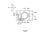
- the housing hole 760a is provided on the one side in the X direction (the orthogonal direction) of the first recess 740a of the first case 700a and in communication with the first recess 740a.
- the housing hole 760a is a through-hole passing in the Z direction from an inner side to an outer side of the first case 700a. More particularly, the housing hole 760a includes an inner opening 762a opening to the inner side and an outer opening 761a opening to the outer side.
- the housing hole 760a has slightly larger dimensions than the outer dimensions of the head 510 of the cable tie 500.
- the housing hole 760a houses the head 510 of the cable tie 500 securely in position in the X and Y directions.
- the head 510 as housed is oriented such that its engaging hole 511 extends in its length direction generally along the extending direction of the housing hole 760a, and that the cut face 521 of the strap 520 is exposed from the outer opening 761a of the housing hole 760a.
- the cut face 521 is located near the head 510. As shown in Fig. 2C , the head 510 and the cut face 521 do not project from the housing hole 760a to the outside of the first case 700a.
- the button 770b is provided at the bottom of the first housing portion 710b and the second housing portion 720b. As shown in Fig. 2A , the distal end of the button 770b is provided with a convex depressing portion 771b, which is located above the convex portions 312 of the first arms 310 of the locking elements 300. When the button 770b is depressed, the depressing portion 771b depresses the convex portions 312 of the first arms 310. The pawls 311 of the first arm 310 accordingly move downward.
- the connector as described above may be manufactured in the following steps.
- the first step is to prepare the contacts 200a, the contacts 200b, and the contact 200c.
- the shielding plates 220b of the contacts 200b are fixed to the tails 212b of the contact bodies 210b in advance.
- the contacts are arrayed in spaced relation in the X direction in a die (not shown) in the order of 200a, 200a, 200b, 200a, 200a, 200b, 200a, 200a, 200b, 200a, 200a, 200a, and 200c.
- An insulating resin is injected into the die to insert-mold the intermediate portions 230a of the contacts 200a, the intermediate portions 213b and the tails 212b of the contact bodies 210b and the front portions of the shielding plates 220b of the contacts 200b, and the intermediate portion 230c and the tail 220c of the contact 200c in the insulating resin.
- the insulating resin hardens to form the second body 400b.
- the contacts are thus embedded in the second body 400b in the array order indicated above.
- the cable 100 and the third body 400c are also prepared.
- the outer insulator 120 and the shield conductor of the first end portion 101 are cut off in advance to make the signal lines 110 stick out.
- the signal lines 110 are respectively inserted into the positioning holes 420c and the positioning recesses 410c in the third body 400c. The signal lines 110 are thus securely positioned in spaced relation along the X direction in the third body 400c.
- the next step is to fit the attaching portion 410b of the second body 400b into the attaching recess 430c of the third body 400c.
- the engaging pieces 411b of the attaching portion 410b engage with the associated engaging recesses 431c of the third body 400c.
- the tails 220a of the contacts 200a are inserted into the respective second slits 450c in the third body 400c, so that the tails 220a pierce through the insulators of the signal lines 110 to hold the cores of the signal lines 110.
- the contacts 200a are thus electrically connected to the signal lines 110 of the cable 100.
- the projecting portions of the shielding plates 220b of the contacts 200b are inserted into the associated first slits 440c in the third body 400c.
- the shielding plates 220b are thus disposed each between one and the other pairs of adjacent tails 220a of the contacts 200a connected to the signal lines 110 as shown in Figs. 2B , 5A , and 5B .
- the locking elements 300 are fixed into the slits 450a in the first body 400a, so that the pawls 311 and the convex portions 312 of the locking elements 300 project upward from the slits 450a.
- the contact portions 210a, 211b, and 210c of the contacts 200a, 200b, and 200c are inserted from the fitting hole 412a of the first body 400a into the associated housing grooves 411a.
- the fitting portion 440b of the second body 400b fits into the fitting hole 412a of the first body 400a.
- the projections 421b of the abutting plates 420b of the second body 400b fit into the holes 431a of the flanges 430a, so that the abutting plates 420b abut the flanges 430a.
- the locking pieces 440a of the first body 400a are locked against the locking pieces 430b of the second body 400b.
- the shield cover 600 is prepared.
- the plate 410a of the first body 400a is inserted into the tube 610 of the shield cover 600.
- the cover 620 of the shield cover 600 covers the flanges 430a and the locking pieces 440a of the first body 400a, the second body 400b, the third body 400c, and the first end portions of the signal lines 110.
- a cable tie is prepared.
- the cable tie at this point is different from the cable tie 500 only in that the strap is not cut.
- the strap of the cable tie is wound around the first end portion 101 of the cable 100, and the strap is inserted into the engaging hole in the head of the cable tie. The strap of the cable tie thus temporarily holds the first end portion 101 of the cable 100.
- the first case 700a is prepared. Into the housing recess 710a of the first case 700a are inserted the cover 620 of the shield cover 600, the flanges 430a and the locking pieces 440a of the first body 400a, the second body 400b, the third body 400c, the rear portions of the contacts 200a, 200b, and 200c, and the first end portions of the signal lines 110. Also, into the housing portion 720a and the opening 730a of the first case 700a are inserted the rear portion of the tube 610 of the shield cover 600, the rear portion of the plate 410a of the first body 400a, and the intermediate portions of the contacts 200a, 200b, and 200c. From the opening 730a project the tube 610 excluding its rear portion of the shield cover 600, the plate 410a excluding its rear portion of the first body 400a, and the distal portions of the contacts 200a, 200b, and 200c.
- the portion of the strap of the cable tie that is drawn from the engaging hole (hereinafter referred to as a drawn portion) is inserted into the housing hole 760a of the first case 700a to place the head of the cable tie in the housing hole 760a.
- the head is thus held in position in the housing hole 760a, with the drawn portion of the strap projecting from the housing hole 760a to the outside of the first case 700a.
- the strap of the cable tie is partially inserted into the first recess 740a of the first case 700a, while the first end portion 101 of the cable 100 is partially inserted into the second recesses 750a and the third recess 770a of the first case 700a.
- the strap is securely positioned in the Y direction in the first recess 740a, while the first end portion 101 of the cable 100 is held in X-direction position in the second recesses 750a.
- the second case 700b is prepared.
- the second case 700b is assembled to the first case 700a. More particularly, the first housing portion 710b of the second case 700b receives the cover 620 of the shield cover 600, the flanges 430a and the locking pieces 440a of the first body 400a, the second body 400b, the third body 400c, the rear portions of the contacts 200a, 200b, and 200c, and the first end portions of the signal lines 110; the second housing portion 720b and the opening 730b of the second case 700b receive the rear portion of the tube 610 of the shield cover 600, the rear portion of the plate 410a of the first body 400a, and the intermediate portions of the contacts 200a, 200b, and 200c; from the opening 730b project the tube 610 excluding its rear portion of the shield cover 600, the plate 410a excluding its rear portion of the first body 400a, and the distal portions of the contacts 200a, 200b, and 200c; the first recess 740b of the second case 700b receives the
- the assembly of the second case 700b to the first case 700a is also conducive to the holding of the strap in position in the Y direction in the first recess 740b and the first end portion 101 of the cable 100 in the X direction in the second recesses 750b.
- the drawn portion of the strap of the cable tie is further fastened by pulling it with a cable tying tool (e.g., TYMATE (registered trademark) manufactured by HellermannTyton) and cutting the drawn portion.
- a cable tying tool e.g., TYMATE (registered trademark) manufactured by HellermannTyton
- the first recesses 740a and 740b restrict movement of the strap in the Y direction but allow movement to one side in the X direction (that is, they guide the strap in the X direction).
- the cable tie with the drawn portion of the strap cut off becomes the cable tie 500.
- the cut face of the strap 520 of the cable tie 500 becomes the cut face 521.
- the cable tie 500 thus ties the signal lines 110 of the first end portion 101 of the cable 100 inside the first case 700a and the second case 700b.
- the drawn portion of the strap of the cable tie may be cut off without using a tying tool.
- an operator may pull the drawn portion to the one side in the X direction to tie the signal lines 110 in the first end portion 101 of the cable 100 with the cable tie, and then cut off the drawn portion with scissors or other tool.
- the cable tie 500 is guided during the tying by the first recesses 740a and 740b of the first case 700a and the second case 700b, and it is pulled in the X direction.
- the first end portion 101 of the cable 100 is held in position in radius direction (including the X direction) inside the second recesses 750a and 750b of the first case 700a and the second case 700b.
- This arrangement can prevent the first end portion 101 of the cable 100 from moving in the X direction in the first case 700a and the second case 700b when tying the first end portion 101 with the cable tie 500 inside the first and second cases 700a, 700b. It is therefore possible to avoid strain on the junctions between the signal lines 110 of the cable 100 and the contacts 200a and also possible to ease the tying work of the cable tie.
- each signal line 110 of the cable 100 is held between the tines of the two-forked tail 220a of each contact 200a. This can more securely maintain the junctions between the signal lines 110 of the cable 100 and the contacts 200a. The junctions, even if under strain, are less like to suffer from disconnections or other troubles.
- the cut face 521 of the strap 520 is exposed from the outer opening 761a of the housing hole 760a. That is, the uncut strap is drawn out of the outer opening 761a through the housing hole 760a, so that the strap can be easily cut at a position near the head 510. In particular, the strap can be easily cut near the head with a tying tool for tying the cable tie 500.
- the first recess 740a and the housing hole 760a are provided between the second recesses 750a.
- the first recess 740a regulates the Y-direction position of the strap 520 of the cable tie 500, while the housing hole 760a regulates the X and Y-direction position of the head 510 of the cable tie 500.
- the second recesses 750a and 750b regulates the radius direction position of the first end portion 101 of the cable 100. This arrangement can improve tension strength of the cable 100.
- the cable tie 500 can be easily positioned with respect to the cable 100, simply by placing the first end portion 101 of the cable 100 in the second recesses 750a and 750b, the strap 520 of the cable tie 500 in the first recesses 740a and 740b, and the head 510 of the cable tie 500 in the housing hole 760a. It is therefore possible to reduce variation in tying position of the cable tie 500 with respect to the cable 100.
- the first case 700a of the above embodiment has the housing recess 710a, the housing portion 720a, the opening 730a, the first recess 740a, the two second recesses 750a, the housing hole 760a, and the third recess 770a.
- the first case of the invention may have any configuration adapted to be assembled to the second case, house the first end portion of the cable, a connecting element (to be described), and the cable tie, and have first and second recesses and a housing hole as described below.
- the first recess 740a of the above embodiment has a dimension in the Y direction that is slightly larger than the width dimension of the strap 520 of the cable tie 500.
- the first recess may have any configuration adapted to receive the strap of the cable tie partially.
- the second recesses 750a of the above embodiment are provided on one and the other side in the Y direction of the first recess 740a.
- at least one second recess 750a will suffice if provided on at least one of one and the other side in the Y direction of the first recess 740a.
- the housing hole 760a of the above embodiment is a through-hole provided on the one side in the X direction of the first recess 740a of the first case 700a to pass through the first case 700a, and it has slightly larger dimensions than the outer dimensions of the head 510 of the cable tie 500.
- the housing hole may be any hole provided on one side in a direction orthogonal to the length direction of the first recess and in communication with the first recess, passing through the first case to house the head of the cable tie.
- the second case 700b of the above embodiment has the first recess 740b and the second recesses 750b.
- the second case may have any configuration adapted to be assembled to the first case and house the first end of the cable, the connecting element (to be described), and the cable tie. It is therefore possible to omit the first recess 740b, the second recesses 750b, and the third recess 760, and/or the button 770b.
- the cable 100 of the above embodiment includes a plurality of signal lines 110.
- the cable of the invention is not limited to this.
- the cable may be a composite cable having different types of signal lines.
- the cable may also be a cable having a single signal line.
- the connecting element as defined in the claims may be a contact 200a of the above embodiment connectable to a signal line 110.
- the connecting element may be any element connectable to a cable.
- the connecting element may be a circuit board or may be a conductive line formed on a body, and the circuit board or conductive line may be connected to a cable or to a signal line of a cable.
- the circuit board or conductive line may also be connected to a contact.
- the contacts 200a of the above embodiment each include a two-forked tail 220a with its tines holding therebetween a signal line 110.
- the tail of each contact may be connected to the cable or a signal line of the cable by soldering. In other words, the tail may or may not be two-forked.
- the connector of the above embodiment includes the first body 400a, the second body 400b, and the third body 400c. However, only a single body is required to hold a connecting element such as a contact.
- the shield cover 600 and/or the engaging sections 300 can be omitted.
Landscapes
- Details Of Connecting Devices For Male And Female Coupling (AREA)
- Package Frames And Binding Bands (AREA)
- Coupling Device And Connection With Printed Circuit (AREA)
Abstract
The invention provides a connector making it possible to prevent a cable from moving during tying a first end portion of the cable with a cable tie inside a case and to thereby improve the operability of the tying work.
The connector includes a first case 700a, and a second case 700b. In use, the connector accommodates a cable 100, a contact 200a and a cable tie 500. The contact 200a is connected to the cable 100. The cable tie 500 includes a head 510 and a strap 520. The head 510 has an engaging hole. The strap 520 ties the first end portion 101 of the cable 100 and is engaged in the engaging hole 511 in the head. The first case 700a has a first recess 740a, a second recess 750a, and an housing hole 760a. The first recess 740a houses the strap 520. The second recess 750a is provided on either side in the Y direction of the first recess 740a, and securely houses the first end portion 101 of the cable 100 in position. The housing hole 760a is provided on a side in the X direction of the first recess 740a and houses the head 510.
Description
- The invention relates to connectors incorporating cable ties.
- As examples of conventional connectors of this type, Japanese Patent Application Laid-Open No.
JP 2002-118936 A JP 56-62683 U - The first connector is configured such that the strap of the cable tie is wound around a first end portion in the length direction of the cable and is engaged in an engaging hole in the head of the cable tie. The cable tie thus ties the first end portion of the cable. The case has a recess and a hole, and the hole is provided in the bottom of the recess to communicate between the recess and the outside of the case. The head of the cable tie fits in the recess of the case, and the portion of the strap that is drawn from the engaging hole in the head (drawn portion) is inserted into the hole in the case.
- In the first connector, the strap of the cable tie is wound around the first end portion of the cable and is engaged into the engaging hole in the head, thereby temporarily fastening the cable tie around the first end portion of the cable. The temporarily fastened cable tie and first end portion of the cable are put into the case, and the drawn portion of the strap of the cable tie is inserted into the hole in the case to fit the head into the recess of the case. Thereafter, the drawn portion of the strap is pulled to further fasten the strap so that the cable tie ties the first end portion of the cable inside the case.
- In the second connector, the case has a block and a recess. The strap of the cable tie is wound around a first end portion in a length direction of the cable and the block of the case, and the strap is engaged in an engaging hole in the head. The cable tie thus ties the first end portion of the cable and the block. The head of the cable tie fits into a recess of the case such that the portion of the strap that is drawn from the engaging hole of the head (drawn portion) is led out of the recess of the case to the outside of the case.
- In the second connector, the cable tie is put into the case to fit the head of the cable tie into the recess of the case. Thereafter, the first end portion of the cable is put into the case, and the strap of the cable tie is wound around the first end portion of the cable and the block, and the strap is engaged into the engaging hole in the head. The cable tie thus ties the first end portion of the cable and the block.
- In the first connector, the head of the cable tie fits in the recess of the case, but the first end portion of the cable is not fixed in position inside the case. When the strap of the cable tie is pulled to tie the first end portion of the cable with the cable tie inside the case, the cable tends to move toward the head of the cable tie, placing strain on the junctions between the cable and the object to be connected.
- On the other hand, in the second connector, it is possible to prevent the movement of the cable by bringing it into abutment with the block of the case when the strap of the cable tie is pulled to tie the first end portion of the cable inside the case. However, the strap of the cable tie is required to be wound around the first end portion of the cable and the block inside the case to engage the strap into the engaging hole of the head. The tying work of the cable is thus difficult.
- The invention has been made in view of the above circumstances. The invention provides a connector making it possible to prevent a cable from moving during tying a first end portion of the cable with a cable tie inside a case and to thereby improve the operability of the tying work.
- In view of the above problems, in a first aspect the invention provides a connector and cable assembly including a cable, a connecting element, a cable tie, and first and second cases. The cable includes a first end portion in a length direction thereof. The connecting element is connected to the cable. The cable tie includes a head and a strap. The head has an engaging hole, and the strap is configured to tie the first end portion of the cable and be engaged in the engaging hole in the head. The first and second cases are combined with each other so as to house the first end portion of the cable, the connecting element, and the cable tie. The first case includes a first recess, a second recess, and a housing hole. The first recess extends in an orthogonal direction orthogonal to the length direction and housing the strap of the cable tie partly. The second recess is provided on at least one of one and the other side in the length direction of the first recess and partly houses the first end portion of the cable securely. The housing hole is provided on one side in the orthogonal direction of the first recess and in communication with the first recess so as to pass through the first case. The housing hole houses the head of the cable tie.
- In the connector and cable assembly of this aspect, the first recess extends in the orthogonal direction; the housing hole is provided on one side in the orthogonal direction of the first recess; and the cable tie temporarily fastening the first end portion of the cable has its strap partly housed in the first recess and its head housed in the housing hole. Therefore, when the portion of the strap of the cable tie that is drawn from the engaging hole is pulled to tie the first end portion of the cable with the cable tie inside the first and second cases, the drawn portion of the strap of the cable tie is pulled to the one side in the orthogonal direction. On the other hand, the first end portion of the cable is securely housed in the second recess. In other words, the first end portion of the cable is held in position inside the second recess. This arrangement can prevent the first end portion of the cable at the time of tying from moving in inside the first and second cases. It is therefore possible to avoid strain on the junctions between the cable and the connecting element and thereby facilitate the tying operation of the cable. In addition, the cable tie can be easily positioned with respect to the cable, simply by housing the first end portion of the cable in the second recess, housing the strap of the cable tie in the first recess, and housing the head of the cable tie in the housing hole. It is therefore possible to reduce variation in tying position of the cable tie with respect to the cable.
- In a preferred embodiment, the first recess may have a dimension in the length direction that is slightly larger than a width dimension of the strap of the cable tie. The housing hole may have slightly larger dimensions than the outer dimensions of the head.
- In the connector and cable assembly of this embodiment, when pulling the portion of the strap of the cable tie that is drawn from the engaging hole, the strap is guided by the first recess and the head is held in position in the housing hole. This arrangement facilitates the tying operation of the cable tie. In addition, the cable tie has its strap held in position in the first recess and its head held in position in the housing hole, resulting in improved tension strength of the cable tied with the cable tie.
- In another preferred embodiment, the second recess may have a dimension in the orthogonal direction that is slightly larger than the outside diameter of the first end portion of the cable for partly housing the first end portion of the cable securely.
- In the connector and cable assembly of this embodiment, the first end portion of the cable is securely housed in the second recess having a dimension in the orthogonal direction that is slightly larger than the outside diameter of the first end portion of the cable. In other words, the first end portion of the cable is held in position in the orthogonal direction inside the second recess. This arrangement can prevent the first end portion of the cable at the time of tying from moving in the orthogonal direction inside the first and second cases. It is therefore possible to avoid strain on the junctions between the cable and the connecting element and thereby facilitate the tying operation of the cable.
- In another preferred embodiment, the second recesses may include a plurality of second recesses provided on one and the other side in the length direction of the first recess. The first recess may be disposed between the second recesses.
- In the connector and cable assembly of this embodiment, the first recess is provided between the second recesses. This can further improve the tension strength of the cable tied with the cable tie.
- In yet another preferred embodiment, the second case may include a first recess and a second recess. The first recess may be configured to partially house the strap of the cable tie, the first recess having a dimension in the length direction that is slightly larger than a width dimension of the strap of the cable tie. The second recess may be provided on at least one of one and the other side in the length direction of the first recess of the second case. The second recess may have a dimension in the orthogonal direction that is slightly larger than the outside diameter of the first end portion of the cable to partially house the first end portion of the cable securely.
- In the connector and cable assembly of this embodiment, when pulling the portion of the strap of the cable tie drawn from the engaging hole, the strap is guided by the first recesses of the first and second cases, thereby facilitating the tying operation of the cable tie. In addition, the strap of the cable tie is held in position in the length direction inside the first recesses of the first and second cases, and the first end portion of the cable is held in position in the orthogonal direction inside the second recesses of the first and second cases. This can improve the tension strength of the cable tied with the cable tie.
- In yet another preferred embodiment, the housing hole in the first case may have an outer opening that is open to the outer side of the first case. The strap of the cable tie may have a distal end face being a cut face. The end face may be exposed from the outer opening of the housing hole.
- If the strap has a cut face facing a wall of the housing hole, it is difficult to cut the strap drawn from the outer opening of the housing hole. However, in the connector and cable assembly of this embodiment of the invention, the strap has the cut face exposed from the outer opening of the housing hole. More particularly, the uncut strap is drawn from the outer opening of the housing hole, it is easy to cut the strap at a position near the head. In particular, the strap can be easily cut near the head by using a tying tool for tying the cable tie.
- In yet another preferred embodiment, the cable may include an outer insulator and a plurality of signal lines disposed inside the outer insulator. The connecting element may include a plurality of connecting elements. The connecting elements may each include a two-forked tail to hold the each signal line between tines thereof so as to establish connection between the connecting elements and the signal lines.
- The connector and cable assembly of this embodiment can more securely maintain the junctions between the signal line of the cable and the connecting elements. The junctions, even if under strain, are less like to suffer from disconnections or other troubles.
- In a second aspect, the invention provides a connector comprising first and second cases combinable with each other and adapted to house, in use, a first end portion in a length direction of an inserted cable, a connecting element, and a cable tie of the type including a head and a strap, the head having an engaging hole. The strap is configured to tie the first end portion of the cable and to be engaged in the engaging hole in the head. The first case includes a first recess extending in an orthogonal direction orthogonal to the length direction. The first recess is adapted to house, in use, the strap of the cable tie partly. The first case further includes a second recess provided on at least one of one and the other side in the length direction of the first recess. The second recesses adapted to house, in use, part of the first end portion of the cable securely. A housing hole is provided on one side in the orthogonal direction of the first recess and in communication with the first recess so as to pass through the first case. The housing hole is adapted to house, in use, the head of the cable tie.
- In the connector of this aspect of the invention, the first recess extends in the orthogonal direction and the housing hole is provided on one side in the orthogonal direction of the first recess. In use, a cable tie temporarily fastening the first end portion of an inserted cable has its strap partly housed in the first recess and its head housed in the housing hole. Therefore, when the portion of the strap of the cable tie that is drawn from the engaging hole is pulled to tie the first end portion of the cable with the cable tie inside the first and second cases, the drawn portion of the strap of the cable tie is pulled to the one side in the orthogonal direction. On the other hand, the first end portion of the cable is securely housed in the second recess. In other words, the first end portion of the cable is held in position inside the second recess. This arrangement can prevent the first end portion of the cable at the time of tying from moving in inside the first and second cases. It is therefore possible to avoid strain on the junctions between the cable and the connecting element and thereby facilitate the tying operation of the cable. In addition, the cable tie can be easily positioned with respect to the cable, simply by housing the first end portion of the cable in the second recess, housing the strap of the cable tie in the first recess, and housing the head of the cable tie in the housing hole. It is therefore possible to reduce variation in tying position of the cable tie with respect to the cable.
- In a preferred embodiment, the first recess may have a dimension in the length direction that is slightly larger than a width dimension of the strap of a cable tie. Also, the housing hole may have slightly larger dimensions than the outer dimensions of the head of the cable tie.
- In the connector of this embodiment, in use, when pulling the portion of the strap of the cable tie that is drawn from the engaging hole, the strap is guided by the first recess and the head is held in position in the housing hole. This arrangement facilitates the tying operation of the cable tie. In addition, the cable tie has its strap held in position in the first recess and its head held in position in the housing hole, resulting in improved tension strength of the cable tied with the cable tie.
- In another preferred embodiment, the second recess may have a dimension in the orthogonal direction that is slightly larger than the outside diameter of the first end portion of a cable to be inserted in the connector.
- In the connector of this embodiment, in use, the first end portion of an inserted cable is securely housed in the second recess having a dimension in the orthogonal direction that is slightly larger than the outside diameter of the first end portion of the cable. In other words, the second recesses adapted to hold the first end portion of the cable in position in the orthogonal direction inside the second recess. This arrangement can prevent the first end portion of the cable at the time of tying from moving in the orthogonal direction inside the first and second cases. It is therefore possible to avoid strain on the junctions between the cable and the connecting element and thereby facilitate the tying operation of the cable.
- In yet another preferred embodiment, the second recess may comprise a plurality of second recesses provided on one and the other side in the length direction of the first recess. The first recess may be disposed between the second recesses.
- In the connector of this embodiment, the first recess is provided between the second recesses. This can further improve the tension strength, in use of an inserted cable tied with a cable tie.
- In yet another preferred embodiment, the second case may include a first recess and a second recess. The first recess may be configured to partially house, in use, the strap of a cable tie, the first recess having a dimension in the length direction that is slightly larger than a width dimension of the strap of the cable tie. The second recess may be provided on at least one of one and the other side in the length direction of the first recess of the second case. The second recess may have a dimension in the orthogonal direction that is slightly larger than the outside diameter of the first end portion of an inserted cable to partially house the first end portion of the cable securely.
- In the connector of this embodiment, in use, when pulling the portion of the strap of a cable tie drawn from the engaging hole, the strap is guided by the first recesses of the first and second cases, thereby facilitating the tying operation of the cable tie. In addition, the strap of the cable tie is held in position in the length direction inside the first recesses of the first and second cases, and the first end portion of an inserted cable is held in position in the orthogonal direction inside the second recesses of the first and second cases. This can improve the tension strength of the cable tied with the cable tie.
- In yet another preferred embodiment, the housing hole in the first case may have an outer opening that is open to the outer side of the first case.
- In the connector of this embodiment, in use, the strap of a cable tie may be drawn from the outer opening of the housing hole so that it is easy to cut the strap at a position near the head of the cable tie. In particular, the strap can be easily cut near the head by using a tying tool for tying the cable tie.
- In yet another preferred embodiment, the connector may further comprise a plurality of connecting elements each including a two-forked tail for holding, in use, between tines thereof each signal line of an inserted cable having an outer insulator and a plurality of signal lines disposed inside the outer insulator for establishing connection between the connecting elements and the signal lines.
- The connector of this embodiment can, in use, more securely maintain the junctions between the signal lines of an inserted cable and the connecting elements. The junctions, even if under strain, are less likely to suffer from disconnections or other troubles.
- The invention will now be described by way of example only and without limitation by reference to the drawings, in which:
-
Fig. 1A is a front, top, right side perspective view of a connector according to an embodiment of the invention. -
Fig. 1B is a rear, bottom, right side perspective view of the connector. -
Fig. 2A is a cross-sectional view of the connector, taken alongline 2A-2A inFig. 1A . -
Fig. 2B is a cross-sectional view of the connector, taken alongline 2B-2B inFig. 1A . -
Fig. 2C is a cross-sectional view of the connector, taken alongline 2C-2C inFig. 1A . -
Fig. 3A is an exploded rear, top, left side perspective view of the connector. -
Fig. 3B is an exploded front, bottom, left perspective view of the connector. -
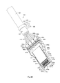
Fig. 4A is a front, top, right side perspective view of a cable, first to third bodies, contacts, locking elements, and a cable tie of the connector. -
Fig. 4B is a rear, bottom, right side perspective view of the cable, first to third bodies, contacts, locking elements, and a cable tie of the connector. -
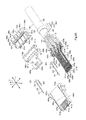
Fig. 5A is an exploded front, top, right side perspective view of the cable, first to third bodies, contacts, locking elements, and a cable tie of the connector. -
Fig. 5B is an exploded rear, bottom, right side perspective view of the cable, the first to third bodies, the contacts, the locking elements, and the cable tie of the connector. -
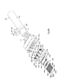
Fig. 6A is a rear, top, left side perspective view of the cable, the second and third bodies, the contacts, the locking elements, and the cable tie of the connector, in a state before the second body is attached to the third body. -
Fig. 6B is a front, bottom, left side perspective view of the cable, the second and third bodies, the contacts, the locking elements, and the cable tie of the connector, in a state before the second body is attached to the third body. - In the brief description of drawings above and the description of embodiments which follows, relative spatial terms such as "upper", "lower", "upward", "downward", "top", "bottom", "left", "right", "front", "rear", "above", etc., are used for the convenience of the skilled reader and refer to the orientation of the connector and cable assembly or the connector and its constituent parts as depicted in the drawings. No limitation is intended by use of these terms, either in use of the invention, during its manufacture, shipment, custody, or sale, or during assembly of its constituent parts or when incorporated into or combined with other apparatus.
- Hereinafter, a connector according to an embodiment of the invention will be described with reference to
Figs. 1A to 6B . The connector includes acable 100, a plurality ofcontacts 200a (connecting element), a plurality ofcontacts 200b, acontact 200c, a pair of lockingelements 300, afirst body 400a, asecond body 400b, athird body 400c, acable tie 500, ashield cover 600, afirst case 700a, and asecond case 700b. These components of the connector will be described below in detail.Figs. 2A ,2B ,3A ,3B ,5A , and5B show the length direction Y of the connector and thecable 100.Figs. 2B ,2C ,3A ,3B ,5A , and5B show the direction X, which is the widthwise direction of the connector and also a direction orthogonal to the length direction of the cable 100 (hereinafter referred to as the "orthogonal direction").Figs. 2A ,2C ,3A ,3B ,5A , and5B show the height direction Z of the connector. The X direction is orthogonal to the Y direction, and the Z direction is orthogonal to the X and Y directions. - As shown in
Figs. 2A to 2C ,3A ,3B, 5A, and 5B, thecable 100 has a plurality ofsignal lines 110, a shield conductor (not shown), and anouter insulator 120. Each of thesignal lines 110 has a core and an insulator covering the core. The shield conductor is tuboid and covers all the signal lines 110. Theouter insulator 120 is tuboid and covers the shield conductor. In other words, thesignal lines 110 are disposed in the shield conductor and theouter insulator 120. Thecable 100 includes afirst end portion 101 in the length direction, in which lengthwise first end portions of thesignal lines 110 project from the shield conductor and theouter insulator 120. It is noted thatFig. 2C does not illustrate the inner configuration of thefirst end portion 101 of thecable 100. - The
cable tie 500 includes ahead 510 and astrap 520 as shown inFigs. 2A to 2C and3A to 6B. Thehead 510 is provided with anengaging hole 511 passing therethrough. The base end of thehead 510 is joined thestrap 520. Thestrap 520 is wound around thefirst end portion 101 of thecable 100 and is engaged in the engaginghole 511. Thecable tie 500 thus ties thesignal lines 110 in thefirst end portion 101 of thecable 100. Thestrap 520 is partly drawn out of theengaging hole 511, and the drawn portion is cut off. That is, the distal end face of thestrap 520 forms acut face 521. - The
third body 400c is a block made of an insulating resin as shown inFigs. 4A to 6B . The lower portion of the front end (one end in the Y direction) of thethird body 400c is provided with a plurality of positioning recesses 410c arranged in spaced relation along the X direction. In addition, the rear end face (the other end face in the Y direction) of thethird body 400c is provided with a plurality ofpositioning holes 420c arranged in spaced relation along the X direction. The positioning holes 420c are open to the rear side (the other side in the Y direction) and extend in the Y direction to communicate with the positioning recesses 410c. The first end portions of thesignal lines 110 of thecable 100 are inserted into the positioning recesses 410c and the positioning holes 420c to be held in position in spaced relation along the X direction. - An attaching
recess 430c is provided in the upper front portion of thethird body 400c. The edges in the X direction of the attachingrecess 430c are each provided with anengaging recess 431c. Thethird body 400c is further provided withfirst slits 440c in spaced relation in the X direction. Thefirst slits 440c extend in the Y direction, from the rear portion of thethird body 400c to the bottom of the attachingrecess 430c. The bottom of the attachingrecess 430c is also provided with a plurality of pairs ofsecond slits 450c, and the pairs are respectively arranged in each space between thefirst slit 440c at each end and the adjacent edge of the attachingrecess 430c and in each space between the adjacentfirst slits 440c. In other words, each of these four pairs is provided in each of the above four spaces. Thesecond slits 450c extend in the X direction and communicate with therespective positioning holes 420c. - The
second body 400b is made of an insulating resin. As shown inFigs. 4A to 6B , thesecond body 400b is embedded with thecontacts second body 400b includes an attachingportion 410b, a pair of abuttingplates 420b, a pair of lockingpieces 430b, and afitting portion 440b. - The attaching
portion 410b is a generally rectangular block forming a rear portion (the other end in the Y direction) of thesecond body 400b. The attachingportion 410b fits in the attachingrecess 430c. Anengaging piece 411b is provided at each end in the X direction of the attachingportion 410b. The engagingpieces 411b are engaged in the associated engagingrecesses 431c of thethird body 400c. - The abutting
plates 420b are generally rectangular plates provided in outer areas in the X direction of the front face of the attachingportion 410b to extend in the Z direction. Aprojection 421b is provided on the front face (one end face in the Y direction) of each of the abuttingplates 420b. Thefitting portion 440b projects from the front center of the attachingportion 410b. The pair of lockingpieces 430b is disposed in spaced relation in the X direction on the lower center of the attachingportion 410b. The lockingpieces 430b extend to the front side (one side in the Y direction). - The
contacts 200a are generally L-shaped metal plates as shown inFigs. 2A ,2B , and4A to 6B . Each of thecontacts 200a includes acontact portion 210a, atail 220a, and anintermediate portion 230a. Theintermediate portion 230a is a plate located between thecontact portion 210a and thetail 220a and embedded in thesecond body 400b. The front portion (one end portion in the Y direction) of theintermediate portion 230a projects from the front face (one end face in the Y direction) of thesecond body 400b to the front side (one side in the Y direction). The rear end (the other end in the Y direction) of theintermediate portion 230a projects from the rear face (the other end face in the Y direction) of the attachingportion 410b of thesecond body 400b. Thecontact portion 210a is a plate contiguous with the front end of theintermediate portion 230a, and it is curved upward in arc shape. Thetail 220a is contiguous with the rear end of theintermediate portion 230a and bent at right angle to theintermediate portion 230a. Thetail 220a is two-forked. Thetails 220a are inserted in the associated second slits 450c in thethird body 400c, in which state thetails 220a each hold between their tines the first end portion of eachsignal line 110 of thecable 100. Specifically, thetails 220a pierce through the insulators of the first end portions of thesignal line 110 and securely hold the cores of the signal lines 110. Thecontacts 200a are thus electrically connected to the signal lines 110. - The
contacts 200b are configured as shown inFigs. 2B and4A to 6B. Thecontacts 200b each include acontact body 210b and ashielding plate 220b. Thecontact body 210b is a metal plate including acontact portion 211b, atail 212b, and anintermediate portion 213b. Theintermediate portion 213b is a plate located between thecontact portion 211b and thetail 212b and embedded in thesecond body 400b. The front portion (one end portion in the Y direction) of theintermediate portion 213b projects from the front face (one end face in the Y direction) of thesecond body 400b to the front side (the one side in the Y direction). Thecontact portion 211b is a plate contiguous with the front end of theintermediate portion 213b, and it is curved upward in arc shape. Thetail 212b is a plate contiguous with the rear end of theintermediate portion 230a. The shieldingplate 220b is a metal plate attached to thetail 212b of thecontact body 210b. Thetail 212b and the front portion (one end portion in the Y direction) of theshielding plate 220b are embedded in the attachingportion 410b of thesecond body 400b. In other words, the portion of theshielding plate 220b other than the front portion (hereinafter referred to as a projecting portion) projects between theadjacent tails 220a of thecontacts 200a from the rear face of the attachingportion 410b to the rear side (the other side in the Y direction). The projecting portions of the shieldingplates 220b are inserted in the associated first slits 440c in thethird body 400c. - The
contact 200c is a metal plate as shown inFigs. 2B and4A to 6B . Thecontact 200c includes acontact portion 210c, atail 220c, and anintermediate portion 230c. Theintermediate portion 230c is a plate located between thecontact portion 210c and thetail 220c and embedded in thesecond body 400b. The front portion (one end portion in the Y direction) of theintermediate portion 230c projects from the front face (one end face in the Y direction) of thesecond body 400b to the front side (the one side in the Y direction). Thecontact portion 210c is a plate contiguous with the front end of theintermediate portion 230c, and it is curved upward in arc shape. Thetail 220c is a plate contiguous with the rear end of theintermediate portion 230c and embedded in the attachingportion 410b of thesecond body 400b. - The
first body 400a is made of an insulating resin. As shown inFigs. 4A to 6B , thefirst body 400a includes aplate 410a, ablock 420a, a pair offlanges 430a, a pair of lockingpieces 440a, and a pair ofslits 450a. Theplate 410a is a generally rectangular plate. The upper front portion (one end in the Y direction) of theplate 410a is recessed (arecess 413a). The front portion of theplate 410a is formed with a plurality ofhousing grooves 411a in spaced relation in the X direction. Thehousing grooves 411a communicate with therecess 413a. Theplate 410a also has a rectangularfitting hole 412a on the rear side (the other end in the Y direction) of thehousing grooves 411a. Thefitting hole 412a communicates with thehousing grooves 411a. Thecontact portions contacts fitting hole 412a into thehousing grooves 411a and exposed upward from thehousing grooves 411a. Thefitting hole 412a fittingly receives thefitting portion 440b of thesecond body 400b. - The
block 420a is generally U-shaped part integrally provided around the rear portion (the other end portion in the Y direction) of theplate 410a. In other words, the rear portion of theplate 410a is integrally disposed between upper end portions (in the one end in the Z direction) of theblock 420a. Theblock 420a has arectangular recess 421a at its lower end (the other end in the Z direction). Theflanges 430a are provided on outer areas in the X direction of the rear face (the other end face in the Y direction) of theblock 420a. Theflanges 430a are rectangular blocks extending further outside than the end faces in the X direction of theblock 420a. The rear faces (the other end faces in the Y direction) of theflanges 430a are each provided with ahole 431a. Theholes 431a fittingly receive theprojections 421b of the abuttingplates 420b of thesecond body 400b such that the abuttingplates 420b abut theflanges 430a. The lockingpieces 440a are provided in the central area of the rear face of theblock 420a. The lockingpieces 440a extend to the rear side (the other side in the Y direction) to be locked against the lockingpieces 430b of thesecond body 400b. - The pair of
slits 450a extends along end portions in the X direction of theplate 410a and theblock 420a. As shown inFigs. 5A to 6A , the lockingelements 300 are generally U-shaped metal plates and fixedly inserted in theslits 450a. Each of the lockingelements 300 has afirst arm 310 and asecond arm 320. Thefirst arm 310 is longer than thesecond arm 320. The distal end of thefirst arm 310 is provided with apawl 311. The proximal portion of thefirst arm 310 is provided with aconvex portion 312. Thepawl 311 and theconvex portion 312 project upward from theslit 450a. - The
shield cover 600 is formed of a metal plate. As shown inFigs. 2A ,2B ,3A , and3B , theshield cover 600 includes atube 610 and acover 620. Thetube 610 has a generally square tuboid inner shape conforming to the outer shape of theplate 410a of thefirst body 400a. Accordingly, thetube 610 fittingly receives theplate 410a. Thetube 610 has a pair ofopenings 611 to allow thepawls 311 of the lockingelements 300 to project upward. Thecover 620 is a generally U-shaped plate contiguously provided with thetube 610 to cover theflanges 430a and the lockingpieces 440a of thefirst body 400a, thesecond body 400b, and thethird body 400c, and the first end portions of the signal lines 110. - The
first case 700a and thesecond case 700b are insulating resin cases assembled together. As shown inFigs. 2A to 3B , thefirst case 700a includes ahousing recess 710a, ahousing portion 720a, anopening 730a, afirst recess 740a, twosecond recesses 750a, ahousing hole 760a, and athird recess 770a. As shown inFigs. 2A to 3B , thesecond case 700b has afirst housing portion 710b, asecond housing portion 720b, anopening 730b, afirst recess 740b, twosecond recesses 750b, athird recess 760b, and abutton 770b. - The
housing recess 710a is provided in the center of thefirst case 700a. Thefirst housing portion 710b is provided in the center of thesecond case 700b. Thehousing recess 710a and thefirst housing portion 710b communicate with each other to define a first housing space. The first housing space houses thecover 620 of theshield cover 600, theflanges 430a and the lockingpieces 440a of thefirst body 400a, thesecond body 400b, thethird body 400c, the rear portions of thecontacts - The
housing portion 720a of thefirst case 700a is a space provided on the front side (the one side in the Y direction) of thehousing recess 710a and in communication with thehousing recess 710a. Theopening 730a is provided on the front side (the one side in the Y direction) of thehousing portion 720a of thefirst case 700a. Theopening 730a is open at its front (the one side in the Y direction) to the outside of thefirst case 700a and communicates at its rear with thehousing portion 720a. Thesecond housing portion 720b of thesecond case 700b is a space provided on the front side (the one side in the Y direction) of thefirst housing portion 710b and in communication with thefirst housing portion 710b. Theopening 730b is open at its front (the one side in the Y direction) to the outside of thesecond case 700b and communicates at its rear with thehousing portion 720b. Thehousing portion 720a, thesecond housing portion 720b, and theopenings tube 610 of theshield cover 600, the rear portion of theplate 410a of thefirst body 400a, and the intermediate portions of thecontacts tube 610 of theshield cover 600 excluding the rear portion, theplate 410a of thefirst body 400a excluding the rear portion, and the distal ends of thecontacts openings first case 700a and thesecond case 700b. - The
third recess 770a is provided on the rear side (the other side in the Y direction) of thehousing recess 710a of thefirst case 700a and in communication with thehousing recess 710a. Thethird recess 760b is provided on the rear side (the other side in the Y direction) of thefirst housing portion 710b of thesecond case 700b and in communication with thefirst housing portion 710b. Thethird recesses first end portion 101 of thecables 100. - The
first recess 740a is provided on the rear side (the other side in the Y direction) of thethird recess 770a of thefirst case 700a. Thefirst recess 740b is provided on the rear side (the other side in the Y direction) of thethird recess 760b of thesecond case 700b. Thefirst recesses first recesses strap 520 of thecable tie 500. Thestrap 520 of thecable tie 500 is received in thefirst recesses - One of the
second recesses 750a is provided on the one side in the Y direction of thefirst recess 740a of thefirst case 700a and in communication with thefirst recess 740a and thethird recess 770a. The othersecond recess 750a is provided on the other side in the Y direction of thefirst recess 740a of thefirst case 700a and in communication with thefirst recess 740a. The othersecond recess 750a is open at its rear (the other side in the Y direction) to the outside of thefirst case 700a. One of thesecond recesses 750b is provided on the one side in the Y direction of thefirst recess 740b of thesecond case 700b and in communication with thefirst recess 740b and thethird recess 760b. The othersecond recess 750b is provided on the other side in the Y direction of thefirst recess 740b of thesecond case 700b and in communication with thefirst recess 740b. The othersecond recess 750b is open at its rear (the other side in the Y direction) to the outside of thesecond case 700b. Thesecond recesses second recesses cable 100. Thefirst end portion 101 of thecable 100 is partially housed in thesecond recesses cable 100. - The
housing hole 760a is provided on the one side in the X direction (the orthogonal direction) of thefirst recess 740a of thefirst case 700a and in communication with thefirst recess 740a. Thehousing hole 760a is a through-hole passing in the Z direction from an inner side to an outer side of thefirst case 700a. More particularly, thehousing hole 760a includes aninner opening 762a opening to the inner side and anouter opening 761a opening to the outer side. Thehousing hole 760a has slightly larger dimensions than the outer dimensions of thehead 510 of thecable tie 500. Thehousing hole 760a houses thehead 510 of thecable tie 500 securely in position in the X and Y directions. Thehead 510 as housed is oriented such that itsengaging hole 511 extends in its length direction generally along the extending direction of thehousing hole 760a, and that thecut face 521 of thestrap 520 is exposed from theouter opening 761a of thehousing hole 760a. Thecut face 521 is located near thehead 510. As shown inFig. 2C , thehead 510 and thecut face 521 do not project from thehousing hole 760a to the outside of thefirst case 700a. - The
button 770b is provided at the bottom of thefirst housing portion 710b and thesecond housing portion 720b. As shown inFig. 2A , the distal end of thebutton 770b is provided with a convexdepressing portion 771b, which is located above theconvex portions 312 of thefirst arms 310 of the lockingelements 300. When thebutton 770b is depressed, thedepressing portion 771b depresses theconvex portions 312 of thefirst arms 310. Thepawls 311 of thefirst arm 310 accordingly move downward. - The connector as described above may be manufactured in the following steps. The first step is to prepare the
contacts 200a, thecontacts 200b, and thecontact 200c. The shieldingplates 220b of thecontacts 200b are fixed to thetails 212b of thecontact bodies 210b in advance. The contacts are arrayed in spaced relation in the X direction in a die (not shown) in the order of 200a, 200a, 200b, 200a, 200a, 200b, 200a, 200a, 200b, 200a, 200a, and 200c. An insulating resin is injected into the die to insert-mold theintermediate portions 230a of thecontacts 200a, theintermediate portions 213b and thetails 212b of thecontact bodies 210b and the front portions of the shieldingplates 220b of thecontacts 200b, and theintermediate portion 230c and thetail 220c of thecontact 200c in the insulating resin. The insulating resin hardens to form thesecond body 400b. The contacts are thus embedded in thesecond body 400b in the array order indicated above. - Also prepared are the
cable 100 and thethird body 400c. In thecable 100, theouter insulator 120 and the shield conductor of thefirst end portion 101 are cut off in advance to make thesignal lines 110 stick out. The signal lines 110 are respectively inserted into the positioning holes 420c and the positioning recesses 410c in thethird body 400c. The signal lines 110 are thus securely positioned in spaced relation along the X direction in thethird body 400c. - The next step is to fit the attaching
portion 410b of thesecond body 400b into the attachingrecess 430c of thethird body 400c. At this point, the engagingpieces 411b of the attachingportion 410b engage with the associated engagingrecesses 431c of thethird body 400c. Also, thetails 220a of thecontacts 200a are inserted into the respectivesecond slits 450c in thethird body 400c, so that thetails 220a pierce through the insulators of thesignal lines 110 to hold the cores of the signal lines 110. Thecontacts 200a are thus electrically connected to thesignal lines 110 of thecable 100. Also, the projecting portions of the shieldingplates 220b of thecontacts 200b are inserted into the associated first slits 440c in thethird body 400c. The shieldingplates 220b are thus disposed each between one and the other pairs ofadjacent tails 220a of thecontacts 200a connected to thesignal lines 110 as shown inFigs. 2B ,5A , and5B . - Also prepared are the
first body 400a and the lockingelements 300. The lockingelements 300 are fixed into theslits 450a in thefirst body 400a, so that thepawls 311 and theconvex portions 312 of the lockingelements 300 project upward from theslits 450a. - Thereafter, the
contact portions contacts fitting hole 412a of thefirst body 400a into the associatedhousing grooves 411a. Also, thefitting portion 440b of thesecond body 400b fits into thefitting hole 412a of thefirst body 400a. Theprojections 421b of the abuttingplates 420b of thesecond body 400b fit into theholes 431a of theflanges 430a, so that the abuttingplates 420b abut theflanges 430a. Also, the lockingpieces 440a of thefirst body 400a are locked against the lockingpieces 430b of thesecond body 400b. - The
shield cover 600 is prepared. Theplate 410a of thefirst body 400a is inserted into thetube 610 of theshield cover 600. Thecover 620 of theshield cover 600 covers theflanges 430a and the lockingpieces 440a of thefirst body 400a, thesecond body 400b, thethird body 400c, and the first end portions of the signal lines 110. - A cable tie is prepared. The cable tie at this point is different from the
cable tie 500 only in that the strap is not cut. The strap of the cable tie is wound around thefirst end portion 101 of thecable 100, and the strap is inserted into the engaging hole in the head of the cable tie. The strap of the cable tie thus temporarily holds thefirst end portion 101 of thecable 100. - The
first case 700a is prepared. Into thehousing recess 710a of thefirst case 700a are inserted thecover 620 of theshield cover 600, theflanges 430a and the lockingpieces 440a of thefirst body 400a, thesecond body 400b, thethird body 400c, the rear portions of thecontacts housing portion 720a and theopening 730a of thefirst case 700a are inserted the rear portion of thetube 610 of theshield cover 600, the rear portion of theplate 410a of thefirst body 400a, and the intermediate portions of thecontacts opening 730a project thetube 610 excluding its rear portion of theshield cover 600, theplate 410a excluding its rear portion of thefirst body 400a, and the distal portions of thecontacts - At this point, the portion of the strap of the cable tie that is drawn from the engaging hole (hereinafter referred to as a drawn portion) is inserted into the
housing hole 760a of thefirst case 700a to place the head of the cable tie in thehousing hole 760a. The head is thus held in position in thehousing hole 760a, with the drawn portion of the strap projecting from thehousing hole 760a to the outside of thefirst case 700a. Also, the strap of the cable tie is partially inserted into thefirst recess 740a of thefirst case 700a, while thefirst end portion 101 of thecable 100 is partially inserted into thesecond recesses 750a and thethird recess 770a of thefirst case 700a. As a result, the strap is securely positioned in the Y direction in thefirst recess 740a, while thefirst end portion 101 of thecable 100 is held in X-direction position in thesecond recesses 750a. - The
second case 700b is prepared. Thesecond case 700b is assembled to thefirst case 700a. More particularly, thefirst housing portion 710b of thesecond case 700b receives thecover 620 of theshield cover 600, theflanges 430a and the lockingpieces 440a of thefirst body 400a, thesecond body 400b, thethird body 400c, the rear portions of thecontacts signal lines 110; thesecond housing portion 720b and theopening 730b of thesecond case 700b receive the rear portion of thetube 610 of theshield cover 600, the rear portion of theplate 410a of thefirst body 400a, and the intermediate portions of thecontacts opening 730b project thetube 610 excluding its rear portion of theshield cover 600, theplate 410a excluding its rear portion of thefirst body 400a, and the distal portions of thecontacts first recess 740b of thesecond case 700b receives the strap of the cable tie partially, while thesecond recesses 750b and thethird recess 760b of thesecond case 700b partly receives thefirst end portion 101 of thecable 100. The assembly of thesecond case 700b to thefirst case 700a is also conducive to the holding of the strap in position in the Y direction in thefirst recess 740b and thefirst end portion 101 of thecable 100 in the X direction in thesecond recesses 750b. - Lastly, the drawn portion of the strap of the cable tie is further fastened by pulling it with a cable tying tool (e.g., TYMATE (registered trademark) manufactured by HellermannTyton) and cutting the drawn portion. At this time, the
first recesses cable tie 500. The cut face of thestrap 520 of thecable tie 500 becomes thecut face 521. Thecable tie 500 thus ties thesignal lines 110 of thefirst end portion 101 of thecable 100 inside thefirst case 700a and thesecond case 700b. The drawn portion of the strap of the cable tie may be cut off without using a tying tool. For example, an operator may pull the drawn portion to the one side in the X direction to tie thesignal lines 110 in thefirst end portion 101 of thecable 100 with the cable tie, and then cut off the drawn portion with scissors or other tool. - The above described connector and cable assembly has at least the following technical features and advantages. Firstly, the
cable tie 500 is guided during the tying by thefirst recesses first case 700a and thesecond case 700b, and it is pulled in the X direction. On the other hand, thefirst end portion 101 of thecable 100 is held in position in radius direction (including the X direction) inside thesecond recesses first case 700a and thesecond case 700b. This arrangement can prevent thefirst end portion 101 of thecable 100 from moving in the X direction in thefirst case 700a and thesecond case 700b when tying thefirst end portion 101 with thecable tie 500 inside the first andsecond cases signal lines 110 of thecable 100 and thecontacts 200a and also possible to ease the tying work of the cable tie. - Secondly, each
signal line 110 of thecable 100 is held between the tines of the two-forkedtail 220a of eachcontact 200a. This can more securely maintain the junctions between thesignal lines 110 of thecable 100 and thecontacts 200a. The junctions, even if under strain, are less like to suffer from disconnections or other troubles. - Thirdly, the
cut face 521 of thestrap 520 is exposed from theouter opening 761a of thehousing hole 760a. That is, the uncut strap is drawn out of theouter opening 761a through thehousing hole 760a, so that the strap can be easily cut at a position near thehead 510. In particular, the strap can be easily cut near the head with a tying tool for tying thecable tie 500. - Fourthly, the
first recess 740a and thehousing hole 760a are provided between thesecond recesses 750a. Thefirst recess 740a regulates the Y-direction position of thestrap 520 of thecable tie 500, while thehousing hole 760a regulates the X and Y-direction position of thehead 510 of thecable tie 500. Thesecond recesses first end portion 101 of thecable 100. This arrangement can improve tension strength of thecable 100. - Fifthly, the
cable tie 500 can be easily positioned with respect to thecable 100, simply by placing thefirst end portion 101 of thecable 100 in thesecond recesses strap 520 of thecable tie 500 in thefirst recesses head 510 of thecable tie 500 in thehousing hole 760a. It is therefore possible to reduce variation in tying position of thecable tie 500 with respect to thecable 100. - The connector of the invention is not limited to the above embodiment but can be modified in any manner within the scope of the claims. Specific modifications will be described in detail below.
- The
first case 700a of the above embodiment has thehousing recess 710a, thehousing portion 720a, theopening 730a, thefirst recess 740a, the twosecond recesses 750a, thehousing hole 760a, and thethird recess 770a. However, the first case of the invention may have any configuration adapted to be assembled to the second case, house the first end portion of the cable, a connecting element (to be described), and the cable tie, and have first and second recesses and a housing hole as described below. - The
first recess 740a of the above embodiment has a dimension in the Y direction that is slightly larger than the width dimension of thestrap 520 of thecable tie 500. The first recess may have any configuration adapted to receive the strap of the cable tie partially. - The second recesses 750a of the above embodiment are provided on one and the other side in the Y direction of the
first recess 740a. However, at least onesecond recess 750a will suffice if provided on at least one of one and the other side in the Y direction of thefirst recess 740a. - The
housing hole 760a of the above embodiment is a through-hole provided on the one side in the X direction of thefirst recess 740a of thefirst case 700a to pass through thefirst case 700a, and it has slightly larger dimensions than the outer dimensions of thehead 510 of thecable tie 500. However, the housing hole may be any hole provided on one side in a direction orthogonal to the length direction of the first recess and in communication with the first recess, passing through the first case to house the head of the cable tie. - The
second case 700b of the above embodiment has thefirst recess 740b and thesecond recesses 750b. However, the second case may have any configuration adapted to be assembled to the first case and house the first end of the cable, the connecting element (to be described), and the cable tie. It is therefore possible to omit thefirst recess 740b, thesecond recesses 750b, and the third recess 760, and/or thebutton 770b. - The
cable 100 of the above embodiment includes a plurality of signal lines 110. However, the cable of the invention is not limited to this. The cable may be a composite cable having different types of signal lines. The cable may also be a cable having a single signal line. - The connecting element as defined in the claims may be a
contact 200a of the above embodiment connectable to asignal line 110. The connecting element may be any element connectable to a cable. For instance, the connecting element may be a circuit board or may be a conductive line formed on a body, and the circuit board or conductive line may be connected to a cable or to a signal line of a cable. In this case, the circuit board or conductive line may also be connected to a contact. Also, thecontacts 200a of the above embodiment each include a two-forkedtail 220a with its tines holding therebetween asignal line 110. However, the tail of each contact may be connected to the cable or a signal line of the cable by soldering. In other words, the tail may or may not be two-forked. - The connector of the above embodiment includes the
first body 400a, thesecond body 400b, and thethird body 400c. However, only a single body is required to hold a connecting element such as a contact. - The
shield cover 600 and/or the engagingsections 300 can be omitted. - It should be appreciated that the above-described embodiment and modifications are described by way of example only. The materials, shapes, dimensions, numbers, arrangements, and other configurations of the connector may be modified as long as they provide similar functions.
-
- 100: Cable
- 101: First end
- 110: Signal line
- 120: Outer insulator
- 200a: Contact (connecting element)
- 210a: Contact portion
- 220a: Tail
- 230a: Intermediate portion
- 200b: Contact
- 210b: Contact body
- 211b: Contact portion
- 212b: Tail
- 213b: Intermediate portion
- 220b: Shielding plate
- 210b: Contact body
- 200c: Contact
- 210c: Contact portion
- 220c: Tail
- 230c: Intermediate portion
- 300: Locking element
- 400a: First body
- 400b: Second body
- 400c: Third body
- 500: Cable tie
- 510: Head
- 511: Engaging hole 600: Shield cover
- 510: Head
- 700a: First case
- 710a: Housing recess
- 720a: Housing portion
- 730a: Opening
- 740a: First recess
- 750a: Second recess
- 760a: Housing hole
- 770a: Third recess
- 700b: Second case
- 710b: First housing portion
- 720b: Second housing portion
- 730b: Opening
- 740b: First recess
- 750b: Second recess
- 760b: Third recess
- 770b: Button
Claims (14)
- A connector and cable assembly comprising:a cable (100) including a first end portion (101) in a length direction (Y) thereof;a connecting element (200a) connected to the cable;a cable tie (500) including a head (510) and a strap (520), the head having an engaging hole (511), the strap being configured to tie the first end portion of the cable and be engaged in the engaging hole in the head; andfirst and second cases (700a, 700b) combined with each other so as to house the first end portion of the cable, the connecting element, and the cable tie, the first case including:a first recess (740a) extending in an orthogonal direction (X) orthogonal to the length direction and housing the strap of the cable tie partly;a second recess (750a) provided on at least one of one and the other side in the length direction of the first recess, the second recess housing part of the first end portion of the cable securely; anda housing hole (760a) provided on one side in the orthogonal direction of the first recess and in communication with the first recess so as to pass through the first case, the housing hole housing the head of the cable tie.
- The connector and cable assembly according to claim 1, wherein the first recess (740a) has a dimension in the length direction (Y) that is slightly larger than a width dimension of the strap (520) of the cable tie (500), and
the housing hole (760a) has slightly larger dimensions than the outer dimensions of the head (510). - The connector and cable assembly according to claim 1 or claim 2 wherein the second recess (750a) has a dimension in the orthogonal direction (X) that is slightly larger than the outside diameter of the first end portion (101) of the cable (100).
- The connector and cable assembly according to any preceding claim, wherein
the second recess (750a) comprises a plurality of second recesses provided on one and the other side in the length direction (Y) of the first recess (740a), and
the first recess is disposed between the second recesses. - The connector and cable assembly according to any preceding claim, wherein the second case (700b) includes:a first recess (740b) configured to partially house the strap (520) of the cable tie (500), the first recess having a dimension in the length direction (Y) that is slightly larger than a width dimension of the strap of the cable tie; anda second recess (750b) provided on at least one of one and the other side in the length direction of the first recess of the second case, the second recess having a dimension in the orthogonal direction (X) that is slightly larger than the outside diameter of the first end portion (101) of the cable (100) to partially house the first end portion of the cable securely.
- The connector and cable assembly according to any preceding claim, wherein
the housing hole (760a) in the first case (700a) has an outer opening (761a) that is open to the outer side of the first case, and
the strap (520) of the cable tie (500) has a distal end face being a cut face (521), the end face being exposed from the outer opening of the housing hole. - The connector and cable assembly according to any preceding claim, wherein the cable (100) includes an outer insulator (120) and a plurality of signal lines (110) disposed inside the outer insulator, and
the connecting element (200a) comprises a plurality of connecting elements, the connecting elements each including a two-forked tail (220a) to hold the each signal line between tines thereof so as to establish connection between the connecting elements and the signal lines. - A connector comprising:first and second cases (700a, 700b) combinable with each other and adapted to house, in use, a first end portion in a length direction (Y) of an inserted cable (100), a connecting element (200a), and a cable tie (500) of the type including a head (510) and a strap (520), the head having an engaging hole (511), the strap being configured to tie the first end portion of the cable and to be engaged in the engaging hole in the head, the first case including:a first recess (740a) extending in an orthogonal direction (X) orthogonal to the length direction and being adapted to house, in use, the strap of the cable tie partly;a second recess (750a) provided on at least one of one and the other side in the length direction of the first recess, the second recess being adapted to house, in use, part of the first end portion of the cable securely; anda housing hole (760a) provided on one side in the orthogonal direction of the first recess and in communication with the first recess so as to pass through the first case, the housing hole being adapted to house, in use, the head of the cable tie.
- The connector according to claim 8, wherein the first recess (740a) has a dimension in the length direction (Y) that is slightly larger than a width dimension of the strap (520) of the cable tie (500), and
the housing hole (760a) has slightly larger dimensions than the outer dimensions of the head (510) of the cable tie (500). - The connector according to claim 8 or claim 9 wherein the second recess (750a) has a dimension in the orthogonal direction (X) that is slightly larger than the outside diameter of the first end portion (101) of the cable (100).
- The connector according to any one of claims 8 to 10, wherein
the second recess (750a) comprises a plurality of second recesses provided on one and the other side in the length direction (Y) of the first recess (740a), and
the first recess is disposed between the second recesses. - The connector according to any one of claims 8 to 11, wherein
the second case (700b) includes:a first recess (740b) configured to partially house the strap (520) of the cable tie (500), the first recess having a dimension in the length direction (Y) that is slightly larger than a width dimension of the strap of the cable tie; anda second recess (750b) provided on at least one of one and the other side in the length direction of the first recess of the second case, the second recess having a dimension in the orthogonal direction (X) that is slightly larger than the outside diameter of the first end portion (101) of the cable (100) to partially house the first end portion of the cable securely. - The connector according to any one of claims 8 to 12, wherein the housing hole (760a) in the first case (700a) has an outer opening (761a) that is open to the outer side of the first case.
- The connector according to any one of claims 8 to 13 for connecting a cable (100) including an outer insulator (120) and a plurality of signal lines (110) disposed inside the outer insulator, wherein the connector further comprises a connecting element (200a) comprising a plurality of connecting elements, the connecting elements each including a two-forked tail (220a) to hold each signal line between tines thereof so as to establish connection between the connecting elements and the signal lines.
Applications Claiming Priority (1)
| Application Number | Priority Date | Filing Date | Title |
|---|---|---|---|
| JP2012203194A JP2014059985A (en) | 2012-09-14 | 2012-09-14 | Connector |
Publications (1)
| Publication Number | Publication Date |
|---|---|
| EP2709215A1 true EP2709215A1 (en) | 2014-03-19 |
Family
ID=49231394
Family Applications (1)
| Application Number | Title | Priority Date | Filing Date |
|---|---|---|---|
| EP13250100.8A Withdrawn EP2709215A1 (en) | 2012-09-14 | 2013-09-05 | Connector |
Country Status (6)
| Country | Link |
|---|---|
| US (1) | US20140080351A1 (en) |
| EP (1) | EP2709215A1 (en) |
| JP (1) | JP2014059985A (en) |
| KR (1) | KR20140035797A (en) |
| CN (1) | CN103682804A (en) |
| TW (1) | TW201414100A (en) |
Families Citing this family (6)
| Publication number | Priority date | Publication date | Assignee | Title |
|---|---|---|---|---|
| JP6597375B2 (en) * | 2016-02-19 | 2019-10-30 | 株式会社オートネットワーク技術研究所 | Wiring structure |
| US10096930B2 (en) * | 2016-02-24 | 2018-10-09 | Hosiden Corporation | Connector |
| EP3376606B1 (en) * | 2017-03-17 | 2021-05-05 | Aptiv Technologies Limited | Cable harness plug |
| JP6792801B2 (en) * | 2017-07-04 | 2020-12-02 | 住友電装株式会社 | Holding structure of slender member |
| JP7322599B2 (en) * | 2019-08-28 | 2023-08-08 | 住友電装株式会社 | connector |
| JP7140733B2 (en) * | 2019-09-26 | 2022-09-21 | 矢崎総業株式会社 | connector cover |
Citations (6)
| Publication number | Priority date | Publication date | Assignee | Title |
|---|---|---|---|---|
| JPS5662683U (en) | 1979-10-22 | 1981-05-27 | ||
| US4842549A (en) * | 1987-04-16 | 1989-06-27 | Amp Incorporated | Dual diameter cable strain relief |
| US5211706A (en) * | 1992-06-09 | 1993-05-18 | Molex Incorporated | Strain relief shell for an electrical connector |
| US6210178B1 (en) * | 1999-04-16 | 2001-04-03 | Pen Cabling Technologies Llc | Extender card |
| JP2002118936A (en) | 2000-10-06 | 2002-04-19 | Hirokimi Kawai | Method and component used for bundling/fixing substance whose thickness varies to specified position |
| US20070193002A1 (en) * | 2006-02-23 | 2007-08-23 | Kabushiki Kaisha Toshiba | Cable tying apparatus and electronic device having cable tying apparatus |
Family Cites Families (1)
| Publication number | Priority date | Publication date | Assignee | Title |
|---|---|---|---|---|
| US4327956A (en) * | 1978-08-07 | 1982-05-04 | E. I. Du Pont De Nemours And Company | Low insertion force dual beam pin terminal and connector |
-
2012
- 2012-09-14 JP JP2012203194A patent/JP2014059985A/en active Pending
-
2013
- 2013-05-30 TW TW102119165A patent/TW201414100A/en unknown
- 2013-06-12 KR KR1020130066971A patent/KR20140035797A/en not_active Withdrawn
- 2013-09-05 EP EP13250100.8A patent/EP2709215A1/en not_active Withdrawn
- 2013-09-10 US US14/022,591 patent/US20140080351A1/en not_active Abandoned
- 2013-09-12 CN CN201310415104.4A patent/CN103682804A/en active Pending
Patent Citations (6)
| Publication number | Priority date | Publication date | Assignee | Title |
|---|---|---|---|---|
| JPS5662683U (en) | 1979-10-22 | 1981-05-27 | ||
| US4842549A (en) * | 1987-04-16 | 1989-06-27 | Amp Incorporated | Dual diameter cable strain relief |
| US5211706A (en) * | 1992-06-09 | 1993-05-18 | Molex Incorporated | Strain relief shell for an electrical connector |
| US6210178B1 (en) * | 1999-04-16 | 2001-04-03 | Pen Cabling Technologies Llc | Extender card |
| JP2002118936A (en) | 2000-10-06 | 2002-04-19 | Hirokimi Kawai | Method and component used for bundling/fixing substance whose thickness varies to specified position |
| US20070193002A1 (en) * | 2006-02-23 | 2007-08-23 | Kabushiki Kaisha Toshiba | Cable tying apparatus and electronic device having cable tying apparatus |
Also Published As
| Publication number | Publication date |
|---|---|
| US20140080351A1 (en) | 2014-03-20 |
| KR20140035797A (en) | 2014-03-24 |
| TW201414100A (en) | 2014-04-01 |
| JP2014059985A (en) | 2014-04-03 |
| CN103682804A (en) | 2014-03-26 |
Similar Documents
| Publication | Publication Date | Title |
|---|---|---|
| EP2600469B1 (en) | Circuit-terminal connecting device | |
| US4171858A (en) | Insulation displacement connector for a flat multi-conductor cable | |
| US20140080351A1 (en) | Connector | |
| EP3002829A1 (en) | Connector | |
| CN105531880B (en) | Cable holding member, arrangements of electric connection, electrical connector, flat cable | |
| EP1819017A2 (en) | Attachment part, and connector and electronic device for connection to same attachment part | |
| US11196199B2 (en) | Connector including holding member for holding conductive member | |
| KR20080012218A (en) | Connector with lock mechanism | |
| US8272894B2 (en) | Coaxial connector | |
| JPH11512222A (en) | Ribbon cable connector assembly | |
| JP6226203B2 (en) | Connector, contact used for connector, housing, housing with electric wire, and method for manufacturing housing with electric wire | |
| KR101439375B1 (en) | Electric connector | |
| JP2013021828A (en) | Attaching structure of binding band | |
| JP6447324B2 (en) | Connector and cable with connector | |
| JP6539834B2 (en) | Simple connection optical connector | |
| JP6041211B2 (en) | Holding plate for automatic transmission, and wiring unit including the same | |
| WO2020085056A1 (en) | Connector | |
| US20020076953A1 (en) | Connecting structure of connector - flexible cable and flexible cable | |
| JP5007161B2 (en) | Electronic component built-in connector | |
| JP2015118790A (en) | Contact for crimp terminal, and electric connector for cable | |
| US20100075537A1 (en) | Connector for terminating a ribbon cable | |
| JP5231297B2 (en) | Electrical connector with caulking shell and shielded cable harness | |
| KR20210039104A (en) | High voltage connector and How to Assemble it | |
| KR20190040947A (en) | Electric wire joint connector | |
| TWM461162U (en) | Connector |
Legal Events
| Date | Code | Title | Description |
|---|---|---|---|
| PUAI | Public reference made under article 153(3) epc to a published international application that has entered the european phase |
Free format text: ORIGINAL CODE: 0009012 |
|
| AK | Designated contracting states |
Kind code of ref document: A1 Designated state(s): AL AT BE BG CH CY CZ DE DK EE ES FI FR GB GR HR HU IE IS IT LI LT LU LV MC MK MT NL NO PL PT RO RS SE SI SK SM TR |
|
| AX | Request for extension of the european patent |
Extension state: BA ME |
|
| STAA | Information on the status of an ep patent application or granted ep patent |
Free format text: STATUS: THE APPLICATION IS DEEMED TO BE WITHDRAWN |
|
| 18D | Application deemed to be withdrawn |
Effective date: 20140920 |