EP2709072A2 - In-vehicle communication system and method of operation - Google Patents
In-vehicle communication system and method of operation Download PDFInfo
- Publication number
- EP2709072A2 EP2709072A2 EP13180524.4A EP13180524A EP2709072A2 EP 2709072 A2 EP2709072 A2 EP 2709072A2 EP 13180524 A EP13180524 A EP 13180524A EP 2709072 A2 EP2709072 A2 EP 2709072A2
- Authority
- EP
- European Patent Office
- Prior art keywords
- receiver
- information
- time interval
- time
- state
- Prior art date
- Legal status (The legal status is an assumption and is not a legal conclusion. Google has not performed a legal analysis and makes no representation as to the accuracy of the status listed.)
- Withdrawn
Links
- 238000004891 communication Methods 0.000 title claims abstract description 19
- 238000000034 method Methods 0.000 title claims description 22
- 230000005540 biological transmission Effects 0.000 claims abstract description 22
- 230000003213 activating effect Effects 0.000 description 2
- 230000004913 activation Effects 0.000 description 2
- 238000010586 diagram Methods 0.000 description 2
- 230000003466 anti-cipated effect Effects 0.000 description 1
- 238000012423 maintenance Methods 0.000 description 1
- 238000004519 manufacturing process Methods 0.000 description 1
- 239000010705 motor oil Substances 0.000 description 1
- 238000012545 processing Methods 0.000 description 1
- 230000004044 response Effects 0.000 description 1
- 238000012360 testing method Methods 0.000 description 1
Images


Classifications
-
- H—ELECTRICITY
- H04—ELECTRIC COMMUNICATION TECHNIQUE
- H04B—TRANSMISSION
- H04B1/00—Details of transmission systems, not covered by a single one of groups H04B3/00 - H04B13/00; Details of transmission systems not characterised by the medium used for transmission
- H04B1/06—Receivers
- H04B1/16—Circuits
- H04B1/1607—Supply circuits
- H04B1/1615—Switching on; Switching off, e.g. remotely
-
- G—PHYSICS
- G07—CHECKING-DEVICES
- G07C—TIME OR ATTENDANCE REGISTERS; REGISTERING OR INDICATING THE WORKING OF MACHINES; GENERATING RANDOM NUMBERS; VOTING OR LOTTERY APPARATUS; ARRANGEMENTS, SYSTEMS OR APPARATUS FOR CHECKING NOT PROVIDED FOR ELSEWHERE
- G07C5/00—Registering or indicating the working of vehicles
- G07C5/008—Registering or indicating the working of vehicles communicating information to a remotely located station
-
- H—ELECTRICITY
- H04—ELECTRIC COMMUNICATION TECHNIQUE
- H04H—BROADCAST COMMUNICATION
- H04H20/00—Arrangements for broadcast or for distribution combined with broadcast
- H04H20/42—Arrangements for resource management
- H04H20/426—Receiver side
-
- H—ELECTRICITY
- H04—ELECTRIC COMMUNICATION TECHNIQUE
- H04W—WIRELESS COMMUNICATION NETWORKS
- H04W52/00—Power management, e.g. Transmission Power Control [TPC] or power classes
- H04W52/02—Power saving arrangements
- H04W52/0209—Power saving arrangements in terminal devices
- H04W52/0212—Power saving arrangements in terminal devices managed by the network, e.g. network or access point is leader and terminal is follower
- H04W52/0216—Power saving arrangements in terminal devices managed by the network, e.g. network or access point is leader and terminal is follower using a pre-established activity schedule, e.g. traffic indication frame
-
- H—ELECTRICITY
- H04—ELECTRIC COMMUNICATION TECHNIQUE
- H04W—WIRELESS COMMUNICATION NETWORKS
- H04W56/00—Synchronisation arrangements
- H04W56/001—Synchronization between nodes
- H04W56/0015—Synchronization between nodes one node acting as a reference for the others
-
- G—PHYSICS
- G07—CHECKING-DEVICES
- G07C—TIME OR ATTENDANCE REGISTERS; REGISTERING OR INDICATING THE WORKING OF MACHINES; GENERATING RANDOM NUMBERS; VOTING OR LOTTERY APPARATUS; ARRANGEMENTS, SYSTEMS OR APPARATUS FOR CHECKING NOT PROVIDED FOR ELSEWHERE
- G07C9/00—Individual registration on entry or exit
- G07C9/00174—Electronically operated locks; Circuits therefor; Nonmechanical keys therefor, e.g. passive or active electrical keys or other data carriers without mechanical keys
- G07C9/00182—Electronically operated locks; Circuits therefor; Nonmechanical keys therefor, e.g. passive or active electrical keys or other data carriers without mechanical keys operated with unidirectional data transmission between data carrier and locks
-
- H—ELECTRICITY
- H04—ELECTRIC COMMUNICATION TECHNIQUE
- H04B—TRANSMISSION
- H04B7/00—Radio transmission systems, i.e. using radiation field
- H04B7/14—Relay systems
- H04B7/15—Active relay systems
- H04B7/185—Space-based or airborne stations; Stations for satellite systems
- H04B7/1851—Systems using a satellite or space-based relay
-
- H—ELECTRICITY
- H04—ELECTRIC COMMUNICATION TECHNIQUE
- H04B—TRANSMISSION
- H04B7/00—Radio transmission systems, i.e. using radiation field
- H04B7/14—Relay systems
- H04B7/15—Active relay systems
- H04B7/185—Space-based or airborne stations; Stations for satellite systems
- H04B7/1851—Systems using a satellite or space-based relay
- H04B7/18515—Transmission equipment in satellites or space-based relays
-
- H—ELECTRICITY
- H04—ELECTRIC COMMUNICATION TECHNIQUE
- H04H—BROADCAST COMMUNICATION
- H04H20/00—Arrangements for broadcast or for distribution combined with broadcast
- H04H20/53—Arrangements specially adapted for specific applications, e.g. for traffic information or for mobile receivers
- H04H20/57—Arrangements specially adapted for specific applications, e.g. for traffic information or for mobile receivers for mobile receivers
-
- H—ELECTRICITY
- H04—ELECTRIC COMMUNICATION TECHNIQUE
- H04H—BROADCAST COMMUNICATION
- H04H2201/00—Aspects of broadcast communication
- H04H2201/70—Aspects of broadcast communication characterised in that receivers can be addressed
-
- Y—GENERAL TAGGING OF NEW TECHNOLOGICAL DEVELOPMENTS; GENERAL TAGGING OF CROSS-SECTIONAL TECHNOLOGIES SPANNING OVER SEVERAL SECTIONS OF THE IPC; TECHNICAL SUBJECTS COVERED BY FORMER USPC CROSS-REFERENCE ART COLLECTIONS [XRACs] AND DIGESTS
- Y02—TECHNOLOGIES OR APPLICATIONS FOR MITIGATION OR ADAPTATION AGAINST CLIMATE CHANGE
- Y02D—CLIMATE CHANGE MITIGATION TECHNOLOGIES IN INFORMATION AND COMMUNICATION TECHNOLOGIES [ICT], I.E. INFORMATION AND COMMUNICATION TECHNOLOGIES AIMING AT THE REDUCTION OF THEIR OWN ENERGY USE
- Y02D30/00—Reducing energy consumption in communication networks
- Y02D30/70—Reducing energy consumption in communication networks in wireless communication networks
Definitions
- This disclosure generally relates to in-vehicle communication system, and more particularly relates to periodically activating a receiver in the system at times when receiver specific information is available to be received.
- In-vehicle communication systems such as ON-STAR® are known. Such communications are useful, for example, to send an 'unlock door' signal from a service provider to the vehicle if the owner/operator of the vehicle inadvertently locks the vehicle keys within the vehicle.
- Such in-vehicle communication systems may also be queried to send a vehicle report to inform the owner about vehicle maintenance issues such as the remaining life of the engine oil, or the present pressure in each of the tires. If a receiver in the vehicle is always on so that all vehicle specific information or messages are received, the receiver may draw too much power from the vehicle battery, especially if the vehicle is parked for long periods of time.
- Described herein is a system and method for operating a receiver of an in-vehicle communications system that periodically turns the receiver on when receiver specific information is expected to be available for reception, and turns the receiver off when possible to conserve battery power.
- an in-vehicle communication system configured to receive signals from a transmitter.
- the transmitter is configured to transmit periodically a time-reference signal and receiver specific information.
- An information transmission time of receiver specific information is timed relative to a reference transmission time of the time-reference signal.
- the system includes a receiver.
- the receiver is characterized as having a receiver identification value.
- the receiver is configured to operate from an off-state to an on-state during an information-expected time interval to receive receiver specific information.
- the information-expected time interval is determined based on a reception time of the time-reference signal and the receiver identification value.
- a method of operating an in-vehicle communication system is provided.
- the system is configured to receive signals from a transmitter.
- the transmitter is configured to transmit periodically a time-reference signal and receiver specific information.
- An information transmission time of receiver specific information is timed relative to a reference transmission time of the time-reference signal.
- the method includes the step of determining a receiver identification value of a receiver of the system.
- the method also includes the step of operating the receiver to detect the time-reference signal.
- the method also includes the step of operating the receiver from an off-state to an on-state during an information-expected time interval to receive receiver specific information.
- the information-expected time interval is determined based on a reception time of the time-reference signal and the receiver identification value.
- Fig. 1 illustrates a non-limiting example of an in-vehicle communication system, hereafter the system 10.
- the system 10 may include a receiver 12 installed in a vehicle 14.
- the receiver 12 may be coupled to a communication buss (not shown) of the vehicle 14 so that signals 16 from a transmitter 18 can be received to, for example, unlock the doors of the vehicle 14.
- the transmitter 18 may be a satellite configured to receive communications from a ground station 20 that, in response to a phone call from the vehicle owner 22, uplinks receiver specific information to the transmitter 18 for generating the signals 16 that include the receiver specific information for the receiver 12.
- the receiver 12 is characterized as having a receiver identification value that may uniquely identify the receiver relative to any other receiver receiving the signals 16, or may identify the receiver 12 as one of a particular collection of receivers that may react similarly to the receiver specific information communicated by the signals 16.
- the receiver identification value may be related to the vehicle identification number (VIN) of the vehicle 14, or may be related to a manufacturing serial number assigned to the receiver 12, or may be a combination thereof.
- the receiver 12 may include a tuner, demodulator, or other circuitry known in the art for receiving and processing the signals 16, such as radio frequency (RF) signals.
- the receiver 12 may include a processor (not shown) such as a microprocessor or other control circuitry as should be evident to those in the art.
- the receiver 12 may include memory, including non-volatile memory, such as electrically erasable programmable read-only memory (EEPROM) for storing one or more routines, thresholds and captured data. The one or more routines may be executed by the processor to perform steps for determining signals received by the receiver 12 as described herein
- Fig. 2 illustrates a non-limiting example of information communicated in time slots of the signals 16 transmitted by the transmitter 18.
- the signals 16 may include a time-reference signal 24 (e.g. 24a, 24b, 24c) and receiver specific information 26 (e.g. 26a, 26b, 26c) that are periodically transmitted.
- the time-reference signal 24 may be based on Coordinated Universal Time (UTC) signal received by the transmitter 18.
- the receiver specific information 26 may include messages for other receivers (not shown) as well as a message specifically for the receiver 12.
- Fig. 2 illustrates an information transmission time 28 that generally marks the beginning of when the receiver specific information 26 is transmitted, and a reference transmission time 30 that generally marks the end of the time-reference signal 24.
- the reference transmission time 30 could mark the beginning of the time-reference signal 24.
- describing the time-reference signal 24 as being transmitted periodically means that the time interval between the time-reference signal 24a and the time-reference signal 24b is essentially equal to the time interval between the time-reference signal 24b and the time-reference signal 24c.
- successive marks for the reference transmission time 30 are equally spaced over time.
- the marks for the information transmission time 28 are equally spaced, and so the time interval between the reference transmission time 30 and the information transmission time 28 that immediately follows is essentially constant.
- Fig. 2 further illustrates a non-limiting example of a receiver activation schedule 32 for the receiver 12.
- the receiver 12 is configured to operate from an off-state to an on-state during an information-expected time interval 34 effective to receive all or part of the receive receiver specific information 26.
- the receiver activation schedule 32 is determined so that the receiver 12 is activated (i.e. powered on) only when information relevant to the receiver 12 is expected to be available for reception.
- the information-expected time interval 34 may be determined based on a reception time 36 of the time-reference signal 24 (i.e. the reference transmission time 30) and the receiver identification value.
- the receiver identification value may be used to determine when a start time 38 based on when the information-expected time interval 34 will begin.
- the last eight (8) bits may be used to determine the start time 38 relative to the reception time 36. Then, the receiver 12 can turn on at a time when relevant information is expected, and otherwise turned off to save battery power. It should be recognized that the timing offset duration would be 'known' to both the receiver 12 and transmitter 18.
- the receiver specific information 26 26a, 26b, or 26c
- the receiver 12 then can turn on, for example, two (2) seconds every five hundred twelve (512) seconds or receiver specific information. The exact 2 seconds that the receiver 12 is on the on-state would be determined an offset duration relative to the reception time 36.
- the transmitter 18 only needs to transmit to the receiver 12 during the information-expected time interval 34. This improves the number of receivers that can be serviced in a broadcast system. At the end of the information-expected time interval 34, the receiver 12 operates from the on-state to the off-state.
- the receiver 12 may operate to the on-state for a synchronization time interval 40 to receive the time-reference signal 24.
- the maximum time of the synchronization time interval 40 would depend on how often the time-reference signal 24 was transmitted, and how many instances of the time-reference signal 24 the receiver 12 would attempt to determine the reception time 36 before stopping because, for example, the vehicle 14 was parked at a location where the signals 16 could not be received.
- an internal timer within the receiver 12 may be relied upon to activate the receiver 12 during a subsequent plurality of information-expected time intervals 34 without having to determine the reference transmission time 30 immediately prior to determining every instance of the start time 38.
- the receiver 12 may be configured to operate repeatedly only during the information-expected time interval 34 after an initial synchronization time interval 40, and before a subsequent synchronization time interval (not shown).
- the receiver 12 can use an internal clock to receive multiple instances of receiver-specific information 26 before having to re-synchronize to the time-reference signal 24.
- the internal clock of the receiver 12 and the clock used to determine when the time-reference signal 24 is transmitted may drift relative to each other, and so after activating the receiver 12 only during the information-expected time interval 34, the receiver 12 may need to resynchronize with the transmitter 18. Since the receiver 12 has some prior 'knowledge' of when a time reference signal may occur, the synchronization time interval 40 used initially by the receiver 12 may be longer than a subsequent synchronization time interval (not shown). The determination of when a subsequent synchronization time interval should be performed may be decided based on several factors.
- the receiver may be configured to operate repeatedly only during the information-expected time interval 34 a predetermined number of instances before the subsequent synchronization time interval.
- Such a strategy could be based on an expected worst case tolerance stack of the difference between the internal clock of the receiver 12, and the time based used by the transmitter 18.
- the receiver 12 may be configured to operate repeatedly only during the information-expected time interval 34 until a time-shift difference between the information-expected time interval 34 and an information-arrival time interval (not shown, but understood to be the actual arrival time) is greater than a time-shift threshold. It is anticipate that the information-expected time interval 34 will be greater than the actual time interval that a message for the specific receiver to allow time for the receiver 12 to synchronize with the signals 16. If the message for the specific receiver arrives at an incremental amount of time different from expected, that difference can be used to determine that a subsequent synchronization should be performed.
- the receiver 12 may be configured to operate repeatedly only during the information-expected time interval 34 if a signal strength during the information-expected time interval 34 is greater than a signal-strength threshold. If the signal strength is too low because, for example, the vehicle is parked in an underground structure, then the receiver may stop any further attempt to detect the signals 16 until, for example, the vehicle 14 is started.
- Fig. 3 illustrates a non-limiting example of a method 300 of operating an in-vehicle communication system (the system 10).
- the system 10 is configured to receive signals 16 from a transmitter configured 18 to transmit periodically a time-reference signal 24 and receiver specific information 26.
- An information transmission time 28 of receiver specific information is timed relative to a reference transmission time 30 of the time-reference signal 24.
- the method 300 is such that the receiver 12 is operated to an on-state (i.e. activated or powered on) only often enough to keep track of a reception time 36 when the time-reference signal 24 is expected to be received, and to receive information directed to the receiver 12 during the information-expected time interval 34.
- Step 310, RECALL RECEIVER ID may include the receiver 12 determining a receiver identification value of the receiver 12, for example, recalling the receiver identification value from memory (not shown) in the receiver 12.
- Step 320 may include operating the receiver 12 to the on-state in preparation for detecting the time-reference signal 24.
- Step 330 DETECT RECEPTION TIME, may include operating the receiver to detect the time-reference signal 24 in order to determine the reception time 36. If there is no prior history of receiving the time-reference signal 24 (i.e. the receiver 12 has no basis for estimating when the time-reference signal 24 may be received), then the receiver 12 may stay on an extended period of time, for example a few minutes, in order to be sure that a time-reference signal 24 has been transmitted by the transmitter 18. If there is prior history of receiving the time-reference signal 24, then the receiver 12 may wait until a few seconds before when a time-reference signal 24 is expected to be received, and then momentarily (e.g. a few seconds) activate the receiver to detect the time-reference signal 24 in order to determine the reception time 36.
- momentarily e.g. a few seconds
- Step 340 may include operating the receiver 12 to the off state immediately after receiving the time-reference signal 24, i.e. immediately after the reception time 36.
- the receiver 12 may remain in the on-state until after the receiver specific information 26a is received. Receiving the receiver specific information 26a may be advantageous to initialize the receiver 12 if some provision for changing the formatting of the receiver specific information 26 is desired.
- Step 350 may include operating the receiver 12 from an off-state to an on-state at the start time 38 so the receiver 12 is ready to receive the signals 16 during an information-expected time interval 34 to receive all or part of the receiver specific information 26.
- the start time 38 may be determined based on a reception time 36 of the time-reference signal 24 and the receiver identification value.
- the step of operating the receiver 12 from an off-state to an on-state during an information-expected time interval 34 may be repeated a plurality of instances before repeating the step of operating the receiver to detect the time-reference signal 24.
- Steps 370, 380, and 390 are optional steps that describe tests that may be performed to determine if the receiver 12 needs to be re-synchronized to the transmitter 18.
- Step 360 RECEIVE RECEIVER SPECIFIC INFORMATION, may include demodulating the signals 16 in order to extract the receiver specific information 26, and may include the receiver outputting a signal to a vehicle communication buss in order to, for example, unlock the vehicle doors.
- Step 370 TURN RECEIVER OFF AFTER INTERVAL, may include operating the receiver 12 from the on-state to the off-state after the information-expected time interval 34.
- Step 380 NUMBER OF INTERVALS > NUMBER THRESHOLD, may include the receiver 12 counting the number of times the receiver 12 is activated during the information-expected time interval 34 without determining a reception time 36. If NO, the method 300 returns to Step 350 to operate the receiver 12 to the on-state during the information-expected time interval 34. As such, Step 350 is repeated a predetermined number of instances. If YES, the method 300 may execute other steps, or may alternatively return to Step 320 in order to re-synchronize the receiver 12 and the transmitter 18 by executing Step 330
- Step 390 TIME SHIFT > TIME SHIFT THRESHOLD, may include determining if the difference between an internal clock of the receiver 12 and an external clock of the transmitter 18 differ by an amount greater than a time-shift threshold. If NO, the method 300 may return to step 350. As such, step of operating the receiver 12 from an off-state to an on-state during an information-expected time interval to receive receiver specific information is repeated until a time-shift difference between the information-expected time interval and an information-arrival time interval is greater than a time-shift threshold.
- Step 400 SIGNAL STRENGTH > SIGNAL-STRENGTH THRESHOLD, may include determining if a signal strength of the signals 16 is greater than a signal-strength threshold. If YES, the method 300 goes to Step 320 to resynchronize the receiver 12 to the transmitter 18. If NO, then method may proceed to Step 410.
- Step 410 WAIT FOR VEHICLE START, may include keeping the receiver 12 in an off-state for an extended period of time (e.g. an hour), or until the vehicle is restarted. This will help prevent unnecessary power draining on the vehicle battery if the vehicle is parked at location where the signals 16 are not receivable.
- an extended period of time e.g. an hour
- an in-vehicle communication system 10 and a method 300 of of operating an in-vehicle communication system is provided.
- a subset can be created based on a modulo version of that number. I.e if 256 values are desired in a subset, only 8 bits of the digitized VIN/ID is needed. These bits are known at the receiver 12 and transmitter 18.
- Unique transmission times are sliced into the same amount as the subset (i.e. 256) and both the receiver and transmitter are pre-determined on what time they will transmit/receive.
- the offset time for each slice is based on a known time that is transmitted by the broadcast system and is known by the receiver 12, or a close estimate can be calculated. This provides a way to ensure the transmitter only transmits messages when it knows the intended receiver is on. It also ensures that the receiver is on only when messages for the receiver are expected to be received.
Landscapes
- Engineering & Computer Science (AREA)
- Signal Processing (AREA)
- Computer Networks & Wireless Communication (AREA)
- Business, Economics & Management (AREA)
- General Business, Economics & Management (AREA)
- Physics & Mathematics (AREA)
- General Physics & Mathematics (AREA)
- Selective Calling Equipment (AREA)
- Lock And Its Accessories (AREA)
Abstract
Description
- This disclosure generally relates to in-vehicle communication system, and more particularly relates to periodically activating a receiver in the system at times when receiver specific information is available to be received.
- In-vehicle communication systems such as ON-STAR® are known. Such communications are useful, for example, to send an 'unlock door' signal from a service provider to the vehicle if the owner/operator of the vehicle inadvertently locks the vehicle keys within the vehicle. Such in-vehicle communication systems may also be queried to send a vehicle report to inform the owner about vehicle maintenance issues such as the remaining life of the engine oil, or the present pressure in each of the tires. If a receiver in the vehicle is always on so that all vehicle specific information or messages are received, the receiver may draw too much power from the vehicle battery, especially if the vehicle is parked for long periods of time.
- Described herein is a system and method for operating a receiver of an in-vehicle communications system that periodically turns the receiver on when receiver specific information is expected to be available for reception, and turns the receiver off when possible to conserve battery power.
- In accordance with one embodiment, an in-vehicle communication system is provided. The system is configured to receive signals from a transmitter. The transmitter is configured to transmit periodically a time-reference signal and receiver specific information. An information transmission time of receiver specific information is timed relative to a reference transmission time of the time-reference signal. The system includes a receiver. The receiver is characterized as having a receiver identification value. The receiver is configured to operate from an off-state to an on-state during an information-expected time interval to receive receiver specific information. The information-expected time interval is determined based on a reception time of the time-reference signal and the receiver identification value.
- In another embodiment, a method of operating an in-vehicle communication system is provided. The system is configured to receive signals from a transmitter. The transmitter is configured to transmit periodically a time-reference signal and receiver specific information. An information transmission time of receiver specific information is timed relative to a reference transmission time of the time-reference signal. The method includes the step of determining a receiver identification value of a receiver of the system. The method also includes the step of operating the receiver to detect the time-reference signal. The method also includes the step of operating the receiver from an off-state to an on-state during an information-expected time interval to receive receiver specific information. The information-expected time interval is determined based on a reception time of the time-reference signal and the receiver identification value.
- Further features and advantages will appear more clearly on a reading of the following detailed description of the preferred embodiment, which is given by way of non-limiting example only and with reference to the accompanying drawings.
- The present invention will now be described, by way of example with reference to the accompanying drawings, in which:
-
Fig. 1 is a diagram of an in-vehicle communication system in accordance with one embodiment; -
Fig. 2 is a timing diagram of signals present in the system ofFig. 1 in accordance with one embodiment; and -
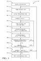
Fig. 3 is a flowchart of steps performed by the system ofFig. 1 in accordance with one embodiment. -
Fig. 1 illustrates a non-limiting example of an in-vehicle communication system, hereafter thesystem 10. Thesystem 10 may include areceiver 12 installed in avehicle 14. Thereceiver 12 may be coupled to a communication buss (not shown) of thevehicle 14 so that signals 16 from atransmitter 18 can be received to, for example, unlock the doors of thevehicle 14. By way of example and not limitation, thetransmitter 18 may be a satellite configured to receive communications from aground station 20 that, in response to a phone call from thevehicle owner 22, uplinks receiver specific information to thetransmitter 18 for generating thesignals 16 that include the receiver specific information for thereceiver 12. In general, thereceiver 12 is characterized as having a receiver identification value that may uniquely identify the receiver relative to any other receiver receiving thesignals 16, or may identify thereceiver 12 as one of a particular collection of receivers that may react similarly to the receiver specific information communicated by thesignals 16. - By way of example and not limitation, the receiver identification value may be related to the vehicle identification number (VIN) of the
vehicle 14, or may be related to a manufacturing serial number assigned to thereceiver 12, or may be a combination thereof. Thereceiver 12 may include a tuner, demodulator, or other circuitry known in the art for receiving and processing thesignals 16, such as radio frequency (RF) signals. Thereceiver 12 may include a processor (not shown) such as a microprocessor or other control circuitry as should be evident to those in the art. Thereceiver 12 may include memory, including non-volatile memory, such as electrically erasable programmable read-only memory (EEPROM) for storing one or more routines, thresholds and captured data. The one or more routines may be executed by the processor to perform steps for determining signals received by thereceiver 12 as described herein -
Fig. 2 illustrates a non-limiting example of information communicated in time slots of thesignals 16 transmitted by thetransmitter 18. Thesignals 16 may include a time-reference signal 24 (e.g. 24a, 24b, 24c) and receiver specific information 26 (e.g. 26a, 26b, 26c) that are periodically transmitted. The time-reference signal 24 may be based on Coordinated Universal Time (UTC) signal received by thetransmitter 18. The receiver specific information 26 may include messages for other receivers (not shown) as well as a message specifically for thereceiver 12. For the purpose of explanation and not limitation,Fig. 2 illustrates aninformation transmission time 28 that generally marks the beginning of when the receiver specific information 26 is transmitted, and areference transmission time 30 that generally marks the end of the time-reference signal 24. It is appreciated that, for example, thereference transmission time 30 could mark the beginning of the time-reference signal 24. As used herein, describing the time-reference signal 24 as being transmitted periodically means that the time interval between the time-reference signal 24a and the time-reference signal 24b is essentially equal to the time interval between the time-reference signal 24b and the time-reference signal 24c. As such, successive marks for thereference transmission time 30 are equally spaced over time. Similarly, the marks for theinformation transmission time 28 are equally spaced, and so the time interval between thereference transmission time 30 and theinformation transmission time 28 that immediately follows is essentially constant. -
Fig. 2 further illustrates a non-limiting example of areceiver activation schedule 32 for thereceiver 12. In general, thereceiver 12 is configured to operate from an off-state to an on-state during an information-expectedtime interval 34 effective to receive all or part of the receive receiver specific information 26. It should be recognized that all of the receiver specific information 26 transmitted by thetransmitter 18 may not be relevant to thereceiver 12, and so thereceiver activation schedule 32 is determined so that thereceiver 12 is activated (i.e. powered on) only when information relevant to thereceiver 12 is expected to be available for reception. As such, as will be explained in more detail below, the information-expectedtime interval 34 may be determined based on areception time 36 of the time-reference signal 24 (i.e. the reference transmission time 30) and the receiver identification value. The receiver identification value may be used to determine when astart time 38 based on when the information-expectedtime interval 34 will begin. - By way of example and not limitation, part of the receiver identification value, the last eight (8) bits for example, may be used to determine the
start time 38 relative to thereception time 36. Then, thereceiver 12 can turn on at a time when relevant information is expected, and otherwise turned off to save battery power. It should be recognized that the timing offset duration would be 'known' to both thereceiver 12 andtransmitter 18. By way of further example, if the last 8 bits are used, the receiver specific information 26 (26a, 26b, or 26c) may be divided into two hundred fifty six (256) distinct time slots. Thereceiver 12 then can turn on, for example, two (2) seconds every five hundred twelve (512) seconds or receiver specific information. The exact 2 seconds that thereceiver 12 is on the on-state would be determined an offset duration relative to thereception time 36. This enables the receiver to be off 99.6% of the time while still being able to receive messages intended for it. Thetransmitter 18 only needs to transmit to thereceiver 12 during the information-expectedtime interval 34. This improves the number of receivers that can be serviced in a broadcast system. At the end of the information-expectedtime interval 34, thereceiver 12 operates from the on-state to the off-state. - If the
receiver 12 has not detected thereception time 36 of the time-reference signal 24, thereceiver 12 may operate to the on-state for asynchronization time interval 40 to receive the time-reference signal 24. The maximum time of thesynchronization time interval 40 would depend on how often the time-reference signal 24 was transmitted, and how many instances of the time-reference signal 24 thereceiver 12 would attempt to determine thereception time 36 before stopping because, for example, thevehicle 14 was parked at a location where thesignals 16 could not be received. Once thereceiver 12 has determined thereception time 36, then an internal timer (not shown) within thereceiver 12 may be relied upon to activate thereceiver 12 during a subsequent plurality of information-expectedtime intervals 34 without having to determine thereference transmission time 30 immediately prior to determining every instance of thestart time 38. As such, thereceiver 12 may be configured to operate repeatedly only during the information-expectedtime interval 34 after an initialsynchronization time interval 40, and before a subsequent synchronization time interval (not shown). In other words, once a time-reference signal 24 is received, thereceiver 12 can use an internal clock to receive multiple instances of receiver-specific information 26 before having to re-synchronize to the time-reference signal 24. - It is anticipated that the internal clock of the
receiver 12 and the clock used to determine when the time-reference signal 24 is transmitted may drift relative to each other, and so after activating thereceiver 12 only during the information-expectedtime interval 34, thereceiver 12 may need to resynchronize with thetransmitter 18. Since thereceiver 12 has some prior 'knowledge' of when a time reference signal may occur, thesynchronization time interval 40 used initially by thereceiver 12 may be longer than a subsequent synchronization time interval (not shown). The determination of when a subsequent synchronization time interval should be performed may be decided based on several factors. - In one embodiment, the receiver may be configured to operate repeatedly only during the information-expected time interval 34 a predetermined number of instances before the subsequent synchronization time interval. Such a strategy could be based on an expected worst case tolerance stack of the difference between the internal clock of the
receiver 12, and the time based used by thetransmitter 18. - In another embodiment, the
receiver 12 may be configured to operate repeatedly only during the information-expectedtime interval 34 until a time-shift difference between the information-expectedtime interval 34 and an information-arrival time interval (not shown, but understood to be the actual arrival time) is greater than a time-shift threshold. It is anticipate that the information-expectedtime interval 34 will be greater than the actual time interval that a message for the specific receiver to allow time for thereceiver 12 to synchronize with thesignals 16. If the message for the specific receiver arrives at an incremental amount of time different from expected, that difference can be used to determine that a subsequent synchronization should be performed. - In another embodiment, the
receiver 12 may be configured to operate repeatedly only during the information-expectedtime interval 34 if a signal strength during the information-expectedtime interval 34 is greater than a signal-strength threshold. If the signal strength is too low because, for example, the vehicle is parked in an underground structure, then the receiver may stop any further attempt to detect thesignals 16 until, for example, thevehicle 14 is started. -
Fig. 3 illustrates a non-limiting example of amethod 300 of operating an in-vehicle communication system (the system 10). In general, thesystem 10 is configured to receivesignals 16 from a transmitter configured 18 to transmit periodically a time-reference signal 24 and receiver specific information 26. Aninformation transmission time 28 of receiver specific information is timed relative to areference transmission time 30 of the time-reference signal 24. In general, themethod 300 is such that thereceiver 12 is operated to an on-state (i.e. activated or powered on) only often enough to keep track of areception time 36 when the time-reference signal 24 is expected to be received, and to receive information directed to thereceiver 12 during the information-expectedtime interval 34. -
Step 310, RECALL RECEIVER ID, may include thereceiver 12 determining a receiver identification value of thereceiver 12, for example, recalling the receiver identification value from memory (not shown) in thereceiver 12. -
Step 320, TURN RECEIVER ON, may include operating thereceiver 12 to the on-state in preparation for detecting the time-reference signal 24. -
Step 330, DETECT RECEPTION TIME, may include operating the receiver to detect the time-reference signal 24 in order to determine thereception time 36. If there is no prior history of receiving the time-reference signal 24 (i.e. thereceiver 12 has no basis for estimating when the time-reference signal 24 may be received), then thereceiver 12 may stay on an extended period of time, for example a few minutes, in order to be sure that a time-reference signal 24 has been transmitted by thetransmitter 18. If there is prior history of receiving the time-reference signal 24, then thereceiver 12 may wait until a few seconds before when a time-reference signal 24 is expected to be received, and then momentarily (e.g. a few seconds) activate the receiver to detect the time-reference signal 24 in order to determine thereception time 36. -
Step 340, TURN RECEIVER OFF, may include operating thereceiver 12 to the off state immediately after receiving the time-reference signal 24, i.e. immediately after thereception time 36. Alternatively, as suggested inFig. 2 , thereceiver 12 may remain in the on-state until after the receiver specific information 26a is received. Receiving the receiver specific information 26a may be advantageous to initialize thereceiver 12 if some provision for changing the formatting of the receiver specific information 26 is desired. -
Step 350, TURN RECEIVER ON AT START TIME, may include operating thereceiver 12 from an off-state to an on-state at thestart time 38 so thereceiver 12 is ready to receive thesignals 16 during an information-expectedtime interval 34 to receive all or part of the receiver specific information 26. Thestart time 38 may be determined based on areception time 36 of the time-reference signal 24 and the receiver identification value. In one embodiment, the step of operating thereceiver 12 from an off-state to an on-state during an information-expectedtime interval 34 may be repeated a plurality of instances before repeating the step of operating the receiver to detect the time-reference signal 24.Steps receiver 12 needs to be re-synchronized to thetransmitter 18. -
Step 360, RECEIVE RECEIVER SPECIFIC INFORMATION, may include demodulating thesignals 16 in order to extract the receiver specific information 26, and may include the receiver outputting a signal to a vehicle communication buss in order to, for example, unlock the vehicle doors. -
Step 370, TURN RECEIVER OFF AFTER INTERVAL, may include operating thereceiver 12 from the on-state to the off-state after the information-expectedtime interval 34. -
Step 380, NUMBER OF INTERVALS > NUMBER THRESHOLD, may include thereceiver 12 counting the number of times thereceiver 12 is activated during the information-expectedtime interval 34 without determining areception time 36. If NO, themethod 300 returns to Step 350 to operate thereceiver 12 to the on-state during the information-expectedtime interval 34. As such,Step 350 is repeated a predetermined number of instances. If YES, themethod 300 may execute other steps, or may alternatively return toStep 320 in order to re-synchronize thereceiver 12 and thetransmitter 18 by executingStep 330 -
Step 390, TIME SHIFT > TIME SHIFT THRESHOLD, may include determining if the difference between an internal clock of thereceiver 12 and an external clock of thetransmitter 18 differ by an amount greater than a time-shift threshold. If NO, themethod 300 may return to step 350. As such, step of operating thereceiver 12 from an off-state to an on-state during an information-expected time interval to receive receiver specific information is repeated until a time-shift difference between the information-expected time interval and an information-arrival time interval is greater than a time-shift threshold. -
Step 400, SIGNAL STRENGTH > SIGNAL-STRENGTH THRESHOLD, may include determining if a signal strength of thesignals 16 is greater than a signal-strength threshold. If YES, themethod 300 goes to Step 320 to resynchronize thereceiver 12 to thetransmitter 18. If NO, then method may proceed to Step 410. -
Step 410, WAIT FOR VEHICLE START, may include keeping thereceiver 12 in an off-state for an extended period of time (e.g. an hour), or until the vehicle is restarted. This will help prevent unnecessary power draining on the vehicle battery if the vehicle is parked at location where thesignals 16 are not receivable. - Accordingly, an in-
vehicle communication system 10 and amethod 300 of of operating an in-vehicle communication system is provided. By using the VIN or unique receiver ID number, a subset can be created based on a modulo version of that number. I.e if 256 values are desired in a subset, only 8 bits of the digitized VIN/ID is needed. These bits are known at thereceiver 12 andtransmitter 18. Unique transmission times are sliced into the same amount as the subset (i.e. 256) and both the receiver and transmitter are pre-determined on what time they will transmit/receive. The offset time for each slice is based on a known time that is transmitted by the broadcast system and is known by thereceiver 12, or a close estimate can be calculated. This provides a way to ensure the transmitter only transmits messages when it knows the intended receiver is on. It also ensures that the receiver is on only when messages for the receiver are expected to be received. - While this invention has been described in terms of the preferred embodiments thereof, it is not intended to be so limited, but rather only to the extent set forth in the claims that follow.
Claims (18)
- An in-vehicle communication system (10) configured to receive signals (16) from a transmitter (18) configured to transmit periodically a time-reference signal (24) and receiver specific information (26), wherein an information transmission time (28) of receiver specific information (26) is timed relative to a reference transmission time (30) of the time-reference signal (24), said system (10) comprising:a receiver (12) characterized as having a receiver identification value, said receiver (12) configured to operate from an off-state to an on-state during an information-expected time interval (34) to receive receiver specific information (26), wherein the information-expected time interval (34) is determined based on a reception time (36) of the time-reference signal (24) and the receiver identification value.
- The system (10) in accordance with claim 1, wherein the receiver (12) is further configured to operate from the on-state to the off-state after the information-expected time interval (34).
- The system (10) in accordance with claim 1, wherein the information-expected time interval (34) is a portion of the time interval when receiver specific information (26) is available for reception.
- The system (10) in accordance with claim 1, wherein the information-expected time interval (34) is based on the reception time (36) and a portion of the receiver identification value.
- The system (10) in accordance with claim 1, wherein the receiver identification value is unique to the receiver (12).
- The system (10) in accordance with claim 1, wherein the receiver identification value is based on a vehicle (14) identification number (VIN) of the vehicle (14) in which the receiver (12) is installed.
- The system (10) in accordance with claim 1, wherein the receiver specific information (26) includes an unlock-vehicle (14)-doors command.
- The system (10) in accordance with claim 1, wherein the receiver (12) is configured to operate during a synchronization time interval (40) to receive the time-reference signal (24), and operate during the information-expected time interval (34) to receive receiver-specific information (26), wherein the receiver (12) is configured to operate repeatedly only during the information-expected time interval (34) after an initial synchronization time interval (40), and before a subsequent synchronization time interval (40).
- The system (10) in accordance with claim 8, wherein the initial synchronization time interval (40) is longer than the subsequent synchronization time interval (40).
- The system (10) in accordance with claim 8, wherein the receiver (12) is configured to operate repeatedly only during the information-expected time interval (34) a predetermined number of instances before the subsequent synchronization time interval (40).
- The system (10) in accordance with claim 8, wherein the receiver (12) is configured to operate repeatedly only during the information-expected time interval (34) until a time-shift difference between the information-expected time interval (34) and an information-arrival time interval is greater than a time-shift threshold.
- The system (10) in accordance with claim 8, wherein the receiver (12) is configured to operate repeatedly only during the information-expected time interval (34) if a signal strength during the information-expected time interval (34) is greater than a signal-strength threshold.
- A method (300) of operating an in-vehicle communication system (10) configured to receive signals (16) from a transmitter (18) configured to transmit periodically a time-reference signal (24) and receiver specific information (26), wherein an information transmission time (28) of receiver specific information (26) is timed relative to a reference transmission time (30) of the time-reference signal (24), said method (300) comprising:determining (310) a receiver identification value of a receiver (12) of the system (10);operating (330) the receiver (12) to detect the time-reference signal (24); andoperating (350) the receiver (12) from an off-state to an on-state during an information-expected time interval (34) to receive receiver specific information (26), wherein the information-expected time interval (34) is determined based on a reception time (36) of the time-reference signal (24) and the receiver identification value.
- The method (300) in accordance with claim 13, wherein the method (300) includes operating (370) the receiver (12) from the on-state to the off-state after the information-expected time interval (34).
- The method (300) in accordance with claim 13, wherein the step of operating (350) the receiver (12) from an off-state to an on-state during an information-expected time interval (34) to receive receiver specific information (26) is repeated a plurality of instances before repeating the step (310) of operating the receiver (12) to detect the time-reference signal (24).
- The method (300) in accordance with claim 15, wherein the step of operating (350) the receiver (12) from an off-state to an on-state during an information-expected time interval (34) to receive receiver specific information (26) is repeated a predetermined number of instances.
- The method (300) in accordance with claim 15, wherein the step of operating (350) the receiver (12) from an off-state to an on-state during an information-expected time interval (34) to receive receiver specific information (26) is repeated until a time-shift difference between the information-expected time interval (34) and an information-arrival time interval is greater than a time-shift threshold.
- The method (300) in accordance with claim 15, wherein the step of operating (350) the receiver (12) from an off-state to an on-state during an information-expected time interval (34) to receive receiver specific information (26) is repeated if a signal strength during the information-expected time interval (34) is greater than a signal-strength threshold.
Applications Claiming Priority (1)
| Application Number | Priority Date | Filing Date | Title |
|---|---|---|---|
| US13/621,960 US8712364B2 (en) | 2012-09-18 | 2012-09-18 | In-vehicle communication system and method of operation |
Publications (2)
| Publication Number | Publication Date |
|---|---|
| EP2709072A2 true EP2709072A2 (en) | 2014-03-19 |
| EP2709072A3 EP2709072A3 (en) | 2017-06-28 |
Family
ID=49165500
Family Applications (1)
| Application Number | Title | Priority Date | Filing Date |
|---|---|---|---|
| EP13180524.4A Withdrawn EP2709072A3 (en) | 2012-09-18 | 2013-08-15 | In-vehicle communication system and method of operation |
Country Status (2)
| Country | Link |
|---|---|
| US (1) | US8712364B2 (en) |
| EP (1) | EP2709072A3 (en) |
Cited By (1)
| Publication number | Priority date | Publication date | Assignee | Title |
|---|---|---|---|---|
| CN110443910A (en) * | 2018-05-03 | 2019-11-12 | 北京京东尚科信息技术有限公司 | State monitoring method, system, device and storage medium of unmanned driving device |
Family Cites Families (15)
| Publication number | Priority date | Publication date | Assignee | Title |
|---|---|---|---|---|
| JPH02261226A (en) | 1989-03-31 | 1990-10-24 | Mitsubishi Electric Corp | Mobile telephone set |
| US5241542A (en) * | 1991-08-23 | 1993-08-31 | International Business Machines Corporation | Battery efficient operation of scheduled access protocol |
| US6236850B1 (en) * | 1999-01-08 | 2001-05-22 | Trw Inc. | Apparatus and method for remote convenience function control with increased effective receiver seek time and reduced power consumption |
| FR2812787B1 (en) * | 2000-08-03 | 2003-01-10 | Matra Nortel Communications | METHOD FOR SYNCHRONIZING MOBILE TERMINALS ON A RADIO CHANNEL IN DIRECT MODE, CONTROL DEVICE AND MOBILE TERMINAL IMPLEMENTING THIS METHOD |
| JP2005076375A (en) * | 2003-09-02 | 2005-03-24 | Denso Corp | Communication device |
| KR100539804B1 (en) | 2003-12-29 | 2006-01-10 | 엘지전자 주식회사 | Apparatus and method for implementing a power saving mode of a telematics terminal |
| US7262684B2 (en) | 2004-10-29 | 2007-08-28 | Lear Corporation | Efficient RKE energy monitoring strategy |
| US7593711B2 (en) | 2005-05-18 | 2009-09-22 | Lojack Operating Company, Lp | Vehicle locating unit with improved power management method |
| US20070139150A1 (en) | 2005-12-15 | 2007-06-21 | Palo Alto Research Center Incorporated | Vapor induced self-assembly and electrode sealing |
| US7903601B2 (en) | 2007-11-08 | 2011-03-08 | Harris Corporation | Asynchronous dynamic network discovery for low power systems |
| JP4509204B2 (en) * | 2008-07-01 | 2010-07-21 | 株式会社日本自動車部品総合研究所 | Receiver |
| JP4726942B2 (en) * | 2008-12-09 | 2011-07-20 | 本田技研工業株式会社 | Vehicle communication system, vehicle communication program |
| US8630605B2 (en) | 2009-10-23 | 2014-01-14 | Lojack Corporation | Synchronization system and method for achieving low power battery operation of a vehicle locating unit in a stolen vehicle recovery system which receives periodic transmissions |
| JP5070318B2 (en) * | 2010-06-21 | 2012-11-14 | 本田技研工業株式会社 | In-vehicle remote control device |
| US20120147800A1 (en) | 2010-12-10 | 2012-06-14 | Minyoung Park | Power management in a wireless network having stations with different power capabilities |
-
2012
- 2012-09-18 US US13/621,960 patent/US8712364B2/en active Active
-
2013
- 2013-08-15 EP EP13180524.4A patent/EP2709072A3/en not_active Withdrawn
Non-Patent Citations (1)
| Title |
|---|
| None |
Cited By (1)
| Publication number | Priority date | Publication date | Assignee | Title |
|---|---|---|---|---|
| CN110443910A (en) * | 2018-05-03 | 2019-11-12 | 北京京东尚科信息技术有限公司 | State monitoring method, system, device and storage medium of unmanned driving device |
Also Published As
| Publication number | Publication date |
|---|---|
| US8712364B2 (en) | 2014-04-29 |
| US20140080438A1 (en) | 2014-03-20 |
| EP2709072A3 (en) | 2017-06-28 |
Similar Documents
| Publication | Publication Date | Title |
|---|---|---|
| US8193915B2 (en) | Multiple transceiver synchronous communication system | |
| JP5594182B2 (en) | Smart system | |
| WO2005034534A3 (en) | Mobile radio communications device and related method of operation and communications system | |
| WO2013074789A2 (en) | Adaptive radio controlled clock employing different modes of operation for different applications and scenarios | |
| JP5290222B2 (en) | Wireless communication device | |
| KR101944785B1 (en) | Portable device and electronic key system | |
| RU2012121948A (en) | BLIND DETECTION OF A HOME UPDATED NODE IN (HENB) FOR HIERARCHICAL CONFIGURATION | |
| CN109561038B (en) | Wireless communication method and device for base station or terminal using wake-up signal | |
| US7509097B2 (en) | Method for determining a measurement time period | |
| WO2009077422A4 (en) | Power control in a wireless communication system | |
| WO2009041547A1 (en) | Radio communication system, base station, mobile station, timing control determining method, and program | |
| US7668259B2 (en) | Signal recognition for combined receiver for remote keyless entry and tire pressure monitoring systems | |
| US8712364B2 (en) | In-vehicle communication system and method of operation | |
| EP2794365B1 (en) | Apparatus and method for receiving signals in a vehicle | |
| RU97122126A (en) | TRANSMITTER AND METHOD OF OVERCOMING FROZEN | |
| JP2012169796A (en) | Radio communication system | |
| EP2913944A2 (en) | Communication system and method of operation | |
| US20140227990A1 (en) | Communication system and method of operation | |
| US7664479B2 (en) | Receiver and method for scanning and receiving wake-up signals with multiple configurations | |
| EP2866461B1 (en) | Signal collecting apparatus, periodic signal transmitting apparatus and signal collecting system | |
| US20110164710A1 (en) | Transmission timing adjustment in radio systems | |
| WO2007070735A2 (en) | Sample-correlated bit-level synchronization | |
| US7702038B2 (en) | Radio frequency (RF) receiver with amplitude-shifted keying/frequency-shifted keying (ASK/FSK) duty cycle optimization algorithm | |
| US20090027170A1 (en) | Two directional information flow in real time location sensing RFID networks | |
| JP5634303B2 (en) | Communication system for vehicle equipment remote control and communication method for vehicle equipment remote control |
Legal Events
| Date | Code | Title | Description |
|---|---|---|---|
| PUAI | Public reference made under article 153(3) epc to a published international application that has entered the european phase |
Free format text: ORIGINAL CODE: 0009012 |
|
| AK | Designated contracting states |
Kind code of ref document: A2 Designated state(s): AL AT BE BG CH CY CZ DE DK EE ES FI FR GB GR HR HU IE IS IT LI LT LU LV MC MK MT NL NO PL PT RO RS SE SI SK SM TR |
|
| AX | Request for extension of the european patent |
Extension state: BA ME |
|
| PUAL | Search report despatched |
Free format text: ORIGINAL CODE: 0009013 |
|
| AK | Designated contracting states |
Kind code of ref document: A3 Designated state(s): AL AT BE BG CH CY CZ DE DK EE ES FI FR GB GR HR HU IE IS IT LI LT LU LV MC MK MT NL NO PL PT RO RS SE SI SK SM TR |
|
| RIC1 | Information provided on ipc code assigned before grant |
Ipc: H04W 52/02 20090101ALN20170523BHEP Ipc: G07C 5/00 20060101AFI20170523BHEP Ipc: G07C 9/00 20060101ALN20170523BHEP Ipc: H04H 20/42 20080101ALN20170523BHEP Ipc: H04W 56/00 20090101ALN20170523BHEP Ipc: H04B 1/16 20060101ALN20170523BHEP |
|
| 17P | Request for examination filed |
Effective date: 20180102 |
|
| RBV | Designated contracting states (corrected) |
Designated state(s): AL AT BE BG CH CY CZ DE DK EE ES FI FR GB GR HR HU IE IS IT LI LT LU LV MC MK MT NL NO PL PT RO RS SE SI SK SM TR |
|
| RAP1 | Party data changed (applicant data changed or rights of an application transferred) |
Owner name: APTIV TECHNOLOGIES LIMITED |
|
| 17Q | First examination report despatched |
Effective date: 20200414 |
|
| STAA | Information on the status of an ep patent application or granted ep patent |
Free format text: STATUS: THE APPLICATION IS DEEMED TO BE WITHDRAWN |
|
| 18D | Application deemed to be withdrawn |
Effective date: 20200825 |