EP2708986A1 - Input device - Google Patents
Input device Download PDFInfo
- Publication number
- EP2708986A1 EP2708986A1 EP12782531.3A EP12782531A EP2708986A1 EP 2708986 A1 EP2708986 A1 EP 2708986A1 EP 12782531 A EP12782531 A EP 12782531A EP 2708986 A1 EP2708986 A1 EP 2708986A1
- Authority
- EP
- European Patent Office
- Prior art keywords
- input
- layout
- input areas
- areas
- area
- Prior art date
- Legal status (The legal status is an assumption and is not a legal conclusion. Google has not performed a legal analysis and makes no representation as to the accuracy of the status listed.)
- Ceased
Links
Images







Classifications
-
- G—PHYSICS
- G06—COMPUTING OR CALCULATING; COUNTING
- G06F—ELECTRIC DIGITAL DATA PROCESSING
- G06F3/00—Input arrangements for transferring data to be processed into a form capable of being handled by the computer; Output arrangements for transferring data from processing unit to output unit, e.g. interface arrangements
- G06F3/01—Input arrangements or combined input and output arrangements for interaction between user and computer
- G06F3/03—Arrangements for converting the position or the displacement of a member into a coded form
- G06F3/041—Digitisers, e.g. for touch screens or touch pads, characterised by the transducing means
-
- G—PHYSICS
- G06—COMPUTING OR CALCULATING; COUNTING
- G06F—ELECTRIC DIGITAL DATA PROCESSING
- G06F3/00—Input arrangements for transferring data to be processed into a form capable of being handled by the computer; Output arrangements for transferring data from processing unit to output unit, e.g. interface arrangements
- G06F3/01—Input arrangements or combined input and output arrangements for interaction between user and computer
- G06F3/048—Interaction techniques based on graphical user interfaces [GUI]
- G06F3/0487—Interaction techniques based on graphical user interfaces [GUI] using specific features provided by the input device, e.g. functions controlled by the rotation of a mouse with dual sensing arrangements, or of the nature of the input device, e.g. tap gestures based on pressure sensed by a digitiser
- G06F3/0488—Interaction techniques based on graphical user interfaces [GUI] using specific features provided by the input device, e.g. functions controlled by the rotation of a mouse with dual sensing arrangements, or of the nature of the input device, e.g. tap gestures based on pressure sensed by a digitiser using a touch-screen or digitiser, e.g. input of commands through traced gestures
- G06F3/04886—Interaction techniques based on graphical user interfaces [GUI] using specific features provided by the input device, e.g. functions controlled by the rotation of a mouse with dual sensing arrangements, or of the nature of the input device, e.g. tap gestures based on pressure sensed by a digitiser using a touch-screen or digitiser, e.g. input of commands through traced gestures by partitioning the display area of the touch-screen or the surface of the digitising tablet into independently controllable areas, e.g. virtual keyboards or menus
-
- G—PHYSICS
- G06—COMPUTING OR CALCULATING; COUNTING
- G06F—ELECTRIC DIGITAL DATA PROCESSING
- G06F3/00—Input arrangements for transferring data to be processed into a form capable of being handled by the computer; Output arrangements for transferring data from processing unit to output unit, e.g. interface arrangements
- G06F3/01—Input arrangements or combined input and output arrangements for interaction between user and computer
- G06F3/048—Interaction techniques based on graphical user interfaces [GUI]
- G06F3/0484—Interaction techniques based on graphical user interfaces [GUI] for the control of specific functions or operations, e.g. selecting or manipulating an object, an image or a displayed text element, setting a parameter value or selecting a range
- G06F3/04847—Interaction techniques to control parameter settings, e.g. interaction with sliders or dials
-
- H—ELECTRICITY
- H04—ELECTRIC COMMUNICATION TECHNIQUE
- H04M—TELEPHONIC COMMUNICATION
- H04M1/00—Substation equipment, e.g. for use by subscribers
- H04M1/02—Constructional features of telephone sets
- H04M1/23—Construction or mounting of dials or of equivalent devices; Means for facilitating the use thereof
-
- H—ELECTRICITY
- H04—ELECTRIC COMMUNICATION TECHNIQUE
- H04M—TELEPHONIC COMMUNICATION
- H04M2250/00—Details of telephonic subscriber devices
- H04M2250/22—Details of telephonic subscriber devices including a touch pad, a touch sensor or a touch detector
Definitions
- the present invention relates to an input device, an input method, and a program for entering information.
- Cellphones available in recent years have an input device that incorporate a touch panel which allows the user to enter characters by touching the touch panel with a finger or bringing a finger close to the touch panel. For entering characters or dialing numbers into the input device combined with the touch panel, the user presses input key buttons displayed on the touch panel to make the entry.
- the user of a small input device such as a cellphone is able to make entries into the input device by carrying the cellphone with one hand and by pressing displayed keys on the touch panel with a finger, e.g., the thumb, of the hand, so that the user does not need to use the other hand.
- a finger e.g., the thumb
- the input device is not user friendly.
- Patent documents are:
- an input device includes:
- an input method for entering information includes:
- a program controls a computer to execute:
- the present invention is able to display input keys that are user friendly.
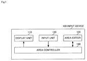
- Fig. 1 is a diagram showing an input device according to an exemplary embodiment of the present invention.
- input device 100 has display unit 110, input unit 120, area editor 130, and area controller 140.
- Input device 100 is applicable as a device having a touch panel function, such as a cellphone, a mobile terminal, a tablet or notebook PC (Personal Computer), an electronic book terminal, a smartphone, a PDA (Personal Digital Assistant), a game machine, or the like.
- a touch panel function such as a cellphone, a mobile terminal, a tablet or notebook PC (Personal Computer), an electronic book terminal, a smartphone, a PDA (Personal Digital Assistant), a game machine, or the like.
- Display unit 110 is a display for displaying a plurality of input areas for entering information.
- the input areas represent general input keys with numerals, alphabetical letters, or Japanese kana characters displayed thereon, and control keys for entering instructions such as making a call, terminating a call, clearing data, and making a decision.
- Input unit 120 enters information based on one of the input areas which includes a position where display unit 110 is touched or approached. For example, when a finger touches an input area representing an input key marked "1", input area 120 enters "1" into input device 100. Display unit 110 and input unit 120 jointly make up a touch panel.
- Area editor 130 edits the layout of input areas. Area editor 130 also edits the shape (size, style, etc.) of input areas in addition to the layout of input areas. For editing the layout and shape of input areas, input unit 120 is used, and area editor 130 edits input areas based on the contents of operations (inputs) on input unit 120.
- Area controller 140 controls input areas displayed on display unit 110 based on an edited result from area editor 130. Specifically, area controller 140 controls the layout of input areas displayed on display unit 110 to change to a layout edited by area editor 130. If area editor 130 edits the layout and shape of input areas, then area controller 140 controls the layout and shape of input areas displayed on display unit 110 to change to the layout and shape edited by area editor 130.
- Fig. 2 is a diagram showing a detailed configuration of input device 100 shown in Fig. 1 .
- input device 100 has display unit 110, input unit 120, area editor 130, area controller 140, action determiner 150, and memory 160.
- Fig. 2 shows only those of the components of input device 100 which are relevant to the present invention.
- Display unit 110 is identical to the display unit shown in Fig. 1 .
- Input unit 120 identical to the input unit shown in Fig. 1 .
- Area editor 130 is identical to the area editor shown in Fig. 1 .
- Action determiner 150 determines a given action.
- action determiner 150 comprises a pressure sensor, and determines which one of the left and right hands of the user is holding input device 100 based on the pressure detected thereby.
- Action determiner 150 then outputs the determined action to area controller 140.
- Memory 160 stores actions determined by action determiner 150 and layouts edited by area editor 130, in association with each other.
- Fig. 3 is a table showing by way of example an association between actions and layouts of input areas that are stored in memory 160 shown in Fig. 2 .
- Memory 160 shown in Fig. 2 stores actions, input area information, and coordinates in association with each other as shown in Fig. 3 .
- ACTIONS represents the contents of actions determined by action determiner 150.
- "INPUT AREA INFORMATION” represents information indicative of input areas. As shown in Fig. 3 , it may represent numerals, characters, etc. that are entered when input areas are selected.
- COORDINATES represents coordinates on display unit 110 that displays input areas, and indicates layouts of input areas.
- the coordinates may be coordinates of the centers of input areas or coordinates of given positions (e.g., upper right comers) in input areas.
- Area controller 140 reads, from memory 160, the layout of input areas which corresponds to an action determined by action determiner 150. Area controller 140 then controls the layout of input areas displayed on display unit 110 to change to the layout read from memory 160. Specifically, if the layout of input areas read from memory 160 is different from the layout that is presently displayed on display unit 110, then area controller 140 changes the layout of input areas displayed on display unit 110 to the layout read from memory 160.
- area controller 140 A specific control process carried out by area controller 140 will be described below with respect to the association shown in Fig. 3 that is stored in memory 160.
- an action “HELD BY LEFT HAND”, input area information “5E” and coordinates (100, 200), input area information “1A” and coordinates (80, 180), and input area information “2B” and coordinates (120, 180) are associated with each other.
- an action “HELD BY RIGHT HAND”, input area information “5E” and coordinates (110, 200), input area information "1A” and coordinates (100, 180), and input area information “2B” and coordinates (140, 180) are associated with each other.
- action determiner 150 determines that the user holds input device 100 with the left hand, then the layout of input areas associated with the action "HELD BY LEFT HAND” is read from memory 160, the input area “5E” is placed at the coordinates (100, 200), the input area “1A” at the coordinates "80, 180", and the input area “2B” at the coordinates "120, 180". If action determiner 150 determines that the user holds input device 100 with the right hand, then the layout of input areas associated with the action "HELD BY RIGHT HAND” is read from memory 160, the input area “5E” is placed at the coordinates (110, 200), the input area “1A” at the coordinates "100, 180", and the input area “2B” at the coordinates "140, 180".
- memory 160 may store an action determined by action determiner 150 and the layout and shape edited by area editor 130.
- area controller 140 reads the layout and shape of input areas corresponding to the action determined by action determiner 150 from memory 160, and controls the layout and shape of input areas displayed on display unit 110 to change to the layout and shape read from memory 160.
- area controller 140 changes the layout and shape of input areas displayed on display unit 110 to change to the layout and shape read from memory 160.
- the association stored in memory 160 may be any association insofar as it allows area controller 140 to acquire the layout and shape of input areas corresponding to the action determined by action determiner 150.
- Fig. 4 is a view showing by way of example the appearance of input device 100 shown in Fig. 2 .
- input device 100 shown in Fig. 2 has dents defined in respective left and right side surfaces of its casing as action determiners 150.
- the dents should preferably be positioned in a range engaged by the index finger when the user holds input device 100 with one hand. If action determiner 150 on the right side in Fig. 4 detects pressure, then it determines that input device 100 is held by the left hand. If action determiner 150 on the left side in Fig. 4 detects pressure, then it determines that input device 100 is held by the right hand.
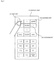
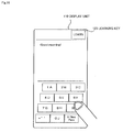
- Fig. 5 is a view showing by way of example a layout of input areas displayed on display unit 110 shown in Fig. 2 .
- input areas representing edit key 121, decision key 122, learning key 123, arrow (direction) keys, a clear key, a call making key, a call terminating key, and alphanumeric keys, etc. are displayed in a given layout on display unit 110.
- Fig. 6 is a flowchart of an editing process for editing a layout of input areas according to the present exemplary embodiment.
- step 1 input unit 120 judges whether or not edit key 121 shown in Fig. 5 is selected. Input unit 120 judges that edit key 121 is selected if it detects that a finger is touching or moving close to edit key 121. Input unit 120 judges that other keys are selected in the same manner.
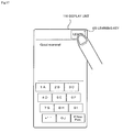
- Fig. 7 is a view showing the manner in which edit key 121 shown in Fig. 5 is selected.
- input unit 120 judges that edit key 121 is selected.
- display unit 110 displays an edit menu in step 2.
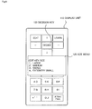
- Fig. 8 is a view showing by way of example an edit menu displayed on display unit 110.
- Edit menu 124 includes a menu for editing the size of input areas (key size), the shape, i.e., style, of input areas, and the layout of input areas (key layout).
- step 3 If "1. KEY SIZE" on edit menu 124 shown in Fig. 8 is selected in step 3, then area editor 130 performs a key size editing process for editing the size of input areas in step 4.
- display unit 110 displays a size menu for designating the size of input areas.
- Fig. 9 is a view showing by way of example a size menu displayed on display unit 110.
- Size menu 125 comprises a menu for selecting the size of input areas (key size) from among "1. LARGE”, “2. MEDIUM”, “3. SMALL", and "4. EXTREMELY SMALL". The user decides on the size of the input areas by selecting a desired one from among the four options. The user carries out the selecting process with respect to each of input areas (keys) whose size needs to be edited. Size menu 125 in Fig. 9 is shown by way of example only. Other size menus which show "EXTREMELY LARGE" and numerical values representing sizes may be used. Sizes may be different when the user holds input device 100 in a vertical orientation and when the user holds input device 100 in a horizontal orientation.
- display unit 110 displays edit menu 124 shown in Fig. 8 .
- area editor 130 may start a key style editing process without display unit 110 displaying edit menu 124.
- display unit 110 displays a style menu for designating the style of input areas.
- Fig. 10 is a view showing by way of example a style menu displayed on display unit 110.
- Style menu 126 is a menu for selecting the style (vertical/horizontal) of input areas from among "1. VERTICALLY LONG", “2. HORIZONTALLY LONG", and "3. VERTICALLY AND HORIZONTALLY EVEN".
- the user decides on the style of input areas by selecting a desired one from among the three options.
- the user carries out the selecting process with respect to each of input areas (keys) whose style needs to be edited.
- Style menu 126 in Fig. 10 is shown by way of example only. Other style menus which show "CIRCULAR", “ELLIPTICAL”, etc. may be used.
- display unit 110 displays edit menu 124 shown in Fig. 8 .
- step 7 If "3. KEY LAYOUT" on edit menu 124 shown in Fig. 8 is selected in step 7, then area editor 130 performs a key layout editing process for editing the layout of input areas in step 8.
- area editor 130 may start a key layout editing process without display unit 110 displaying edit menu 124.
- area editor 130 edits the position of each of the input areas. For example, display unit 110 may highlight each displayed key (e.g., by changing the display color thereof or enlarging the frame of each displayed key, etc.) and the user may bring a finger into touch with or close to a position where the highlighted key is to be placed, thereby determining the position of the key (input area).
- display unit 110 may highlight each displayed key (e.g., by changing the display color thereof or enlarging the frame of each displayed key, etc.) and the user may bring a finger into touch with or close to a position where the highlighted key is to be placed, thereby determining the position of the key (input area).
- area editor 130 When the layout editing process is completed with respect to all the input areas whose layout needs to be edited and decision key 122 is selected, area editor 130 performs an action editing process for editing the contents of an action in step 9.
- display unit 110 displays an action menu for designating an action.
- Fig. 11 is a view showing by way of example an action menu displayed on display unit 110.
- Action menu 127 is a menu for selecting contents of an action to be determined by action determiner 150 from "1. LEFT HAND” and "2. RIGHT HAND". The user decides on contents of an action to be determined by an action determiner 150 by selecting a desired one of the two options.
- Action menu 127 in Fig. 11 is shown by way of example only. Other action menus which show "IN COMMON WITH LEFT AND RIGHT HANDS", etc. may be used.
- action determiner 150 When the contents of an action to be determined by action determiner 150 are selected, the action editing process is completed, and area controller 140 performs a registration process for registering the contents edited thus far in memory 160 in step 10.
- Fig. 12 is a view showing by way of example a registration menu displayed on display unit 110 in a registration process.
- display unit 110 displays thereon registration menu 128 which represents a message for confirming whether or not edited contents are to be registered.
- a plurality of registration entries may be made rather than one registration entry with respect to each of the left and right hands. Furthermore, a plurality of registration entries may be made regardless of an action that is made as representing the left hand or the right hand, i.e., by designating "IN COMMON WITH LEFT AND RIGHT HANDS" in editing an action.
- Fig. 13 is a flowchart of a display process for controlling and displaying the layout of input areas according to the present exemplary embodiment.
- action determiner 150 judges which one of the left and right hands the user who is holding input device 100 is using to hold input device 100.
- area determiner 140 reads the layout of input area that corresponds to the action representing the left hand from memory 160 in step 12.
- area determiner 140 reads the layout of input area that corresponds to the action representing the right hand from memory 160 in step 13.
- step 14 area controller 140 changes the layout of input areas displayed on display unit 110 to the layout read from memory 160, and the display unit 110 displays the changed layout of input areas. After the layout has been changed, information will be entered into the input areas in the changed layout.
- Fig. 14 is a view showing the manner in which input device 100 is held by both hands.
- Fig. 15 is a view showing the manner in which input device 100 is held by the left hand.
- Fig. 16 is a view showing the manner in which input device 100 is held by the right hand.
- the layout of input areas is controlled depending on the way in which the user is holding input device 100.
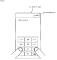
- Fig. 17 is a view showing by way of example input areas laid out on display unit 110.
- area controller 140 While input areas are being laid out on display unit 110 as shown in Fig. 17 , when the user selects learning key 123, area controller 140 reads a plurality of registration entries from memory 160, and changes to the layout that is read.
- Fig. 18 is a view showing by way of example input areas that are laid out on display unit 110 after learning key 123 is selected while input areas are being laid out as shown in Fig. 17 .
- area controller 140 reads one of a plurality of registration entries from memory 160 and changes to the layout that is read.
- area controller 140 successively reads the registration entries from memory 160, and changes to the layouts of the registration entries that are read.
- the layout and shape of input areas may be registered with respect to each of the applications involved, and the layout and shape of input areas may be controlled depending on one of the applications that is activated.
- information that is displayed in the input areas represents numerals and characters (alphabetic characters "A” through “J” for illustrative purposes).
- the characters may include Japanese kana characters and alphabetic characters.
- Numerals, kana characters, and alphabetic characters (a, b, c, etc.) may be controlled so as to belong to positions that are different from each other.
- "5" and "A” belong to the same input area in the above example.
- "5" and "A” may be controlled so as to belong to input areas that are different from each other.
- numerals and characters may be controlled so as to be displayed in different combinations, e.g., "5A” and "5E".
- control keys such as edit key 121, decision key 122, and learning key 123 may also be controlled.
- the layouts of input keys (input areas) that the user prefers depending on the left and right hands that the user uses in holding the input device are stored.
- the input device displays one of the layouts of input keys based on the hand that is determined as holding the input device. Therefore, the input device allows the user to enter information quickly with either one of the hands and also to make less entry errors.
- a computer program that is descriptive of the processing sequences may be recorded in a recording medium that can be read by input device 100, and may be read and executed by input device 100.
- the recording medium that can be read by input device 100 may be a removable recording medium such as a floppy (registered trademark) disk, a magnetooptical disk, a DVD, a CD, or the like, or memory 160, a memory such as a ROM, RAM, or the like, or a HDD or the like in input device 100.
- the program recorded in the recording medium is read by a CPU (not shown) of input device 100, and performs the same processes as those described above under the control of the CPU.
- the CPU operates as a computer that executes the program read from the recording medium in which the program is recorded.
Landscapes
- Engineering & Computer Science (AREA)
- General Engineering & Computer Science (AREA)
- Theoretical Computer Science (AREA)
- Human Computer Interaction (AREA)
- Physics & Mathematics (AREA)
- General Physics & Mathematics (AREA)
- User Interface Of Digital Computer (AREA)
- Position Input By Displaying (AREA)
- Telephone Function (AREA)
Abstract
Description
- The present invention relates to an input device, an input method, and a program for entering information.
- Cellphones available in recent years have an input device that incorporate a touch panel which allows the user to enter characters by touching the touch panel with a finger or bringing a finger close to the touch panel. For entering characters or dialing numbers into the input device combined with the touch panel, the user presses input key buttons displayed on the touch panel to make the entry.
- The user of a small input device such as a cellphone is able to make entries into the input device by carrying the cellphone with one hand and by pressing displayed keys on the touch panel with a finger, e.g., the thumb, of the hand, so that the user does not need to use the other hand. When the user enters characters in this manner, the user finds it difficult to press input keys displayed in the vicinity of the base of the thumb and is liable to make entry errors. Therefore, the input device is not user friendly.
- Technologies have been developed for changing the layout of input keys to a suitable layout depending on the entry to be made (see, for example,
Patent documents 1, 2). -
- Patent document 1:
JP2008-027183A - Patent document 2:
JP2010-182071A - According to the technologies disclosed in
Patent documents - It is an object of the present invention to provide an input device, an input method, and a program which will solve the above problems.
- According to the present invention, an input device includes:
- a display unit that displays a plurality of input areas for entering information;
- an input unit that enters information based on one of the input areas which includes a position that is touched or approached;
- an area editor that edits a layout of the input areas based on an input applied to the input unit; and
- an area controller that controls the input areas displayed by the display unit based on the edited layout from the area editor.
- According to the present invention, an input method for entering information includes:
- a process of displaying a plurality of input areas for entering information;
- an input process of entering information based on one of the input areas which includes a position that is touched or approached;
- a process of editing a layout of the input areas based on an input applied in the input process; and
- a process of controlling the displayed input areas based on the edited layout.
- According to the present invention, a program controls a computer to execute:
- a procedure for displaying a plurality of input areas for entering information;
- an input procedure of entering information based on one of the input areas which includes a position that is touched or approached;
- a procedure for editing a layout of the input areas based on an input applied in the input procedure; and
- a procedure for controlling the displayed input areas based on the edited layout. Advantages of the invention:
- As described above, the present invention is able to display input keys that are user friendly.
-
-
Fig. 1 is a diagram showing an input device according to an exemplary embodiment of the present invention; -
Fig. 2 is a diagram showing a detailed configuration of the input device shown inFig. 1 ; -
Fig. 3 is a table showing by way of example an association between actions and layouts of input areas that are stored in a memory shown inFig. 2 ; -
Fig. 4 is a view showing by way of example the appearance of the input device shown inFig. 2 ; -
Fig. 5 is a view showing by way of example a layout of input areas displayed on a display unit shown inFig. 2 ; -
Fig. 6 is a flowchart of an editing process for editing a layout of input areas according to the exemplary embodiment; -
Fig. 7 is a view showing the manner in which an edit key shown inFig. 5 is selected; -
Fig. 8 is a view showing by way of example an edit menu displayed on the display unit; -
Fig. 9 is a view showing by way of example a size menu displayed on the display unit; -
Fig. 10 is a view showing by way of example a style menu displayed on the display unit; -
Fig. 11 is a view showing by way of example an action menu displayed on the display unit; -
Fig. 12 is a view showing by way of example a registration menu displayed on the display unit in a registration process; -
Fig. 13 is a flowchart of a display process for controlling and displaying a layout of input areas according to the exemplary embodiment; -
Fig. 14 is a view showing the manner in which the input device is held by both hands; -
Fig. 15 is a view showing the manner in which the input device is held by a left hand; -
Fig. 16 is a view showing the manner in which the input device is held by a right hand; -
Fig. 17 is a view showing by way of example input areas laid out on the display unit; and -
Fig. 18 is a view showing by way of example input areas laid out on the display unit after a learning key is selected while input areas are being laid out as shown inFig. 17 . - An exemplary embodiment of the present invention will be described below with reference to the drawings.
-
Fig. 1 is a diagram showing an input device according to an exemplary embodiment of the present invention. - As shown in
Fig. 1 ,input device 100 according to the present exemplary embodiment hasdisplay unit 110,input unit 120,area editor 130, andarea controller 140.Input device 100 is applicable as a device having a touch panel function, such as a cellphone, a mobile terminal, a tablet or notebook PC (Personal Computer), an electronic book terminal, a smartphone, a PDA (Personal Digital Assistant), a game machine, or the like. -
Display unit 110 is a display for displaying a plurality of input areas for entering information. The input areas represent general input keys with numerals, alphabetical letters, or Japanese kana characters displayed thereon, and control keys for entering instructions such as making a call, terminating a call, clearing data, and making a decision. -
Input unit 120 enters information based on one of the input areas which includes a position wheredisplay unit 110 is touched or approached. For example, when a finger touches an input area representing an input key marked "1",input area 120 enters "1" intoinput device 100.Display unit 110 andinput unit 120 jointly make up a touch panel. -
Area editor 130 edits the layout of input areas.Area editor 130 also edits the shape (size, style, etc.) of input areas in addition to the layout of input areas. For editing the layout and shape of input areas,input unit 120 is used, andarea editor 130 edits input areas based on the contents of operations (inputs) oninput unit 120. -
Area controller 140 controls input areas displayed ondisplay unit 110 based on an edited result fromarea editor 130. Specifically,area controller 140 controls the layout of input areas displayed ondisplay unit 110 to change to a layout edited byarea editor 130. Ifarea editor 130 edits the layout and shape of input areas, thenarea controller 140 controls the layout and shape of input areas displayed ondisplay unit 110 to change to the layout and shape edited byarea editor 130. -
Fig. 2 is a diagram showing a detailed configuration ofinput device 100 shown inFig. 1 . - As shown in
Fig. 2 ,input device 100 according to the present exemplary embodiment hasdisplay unit 110,input unit 120,area editor 130,area controller 140,action determiner 150, andmemory 160.Fig. 2 shows only those of the components ofinput device 100 which are relevant to the present invention. -
Display unit 110 is identical to the display unit shown inFig. 1 . -
Input unit 120 identical to the input unit shown inFig. 1 . -
Area editor 130 is identical to the area editor shown inFig. 1 . -
Action determiner 150 determines a given action. For example,action determiner 150 comprises a pressure sensor, and determines which one of the left and right hands of the user is holdinginput device 100 based on the pressure detected thereby.Action determiner 150 then outputs the determined action toarea controller 140. -
Memory 160 stores actions determined byaction determiner 150 and layouts edited byarea editor 130, in association with each other. -
Fig. 3 is a table showing by way of example an association between actions and layouts of input areas that are stored inmemory 160 shown inFig. 2 . -
Memory 160 shown inFig. 2 stores actions, input area information, and coordinates in association with each other as shown inFig. 3 . - "ACTIONS" represents the contents of actions determined by
action determiner 150. - "INPUT AREA INFORMATION" represents information indicative of input areas. As shown in
Fig. 3 , it may represent numerals, characters, etc. that are entered when input areas are selected. - "COORDINATES" represents coordinates on
display unit 110 that displays input areas, and indicates layouts of input areas. The coordinates may be coordinates of the centers of input areas or coordinates of given positions (e.g., upper right comers) in input areas. -
Area controller 140 reads, frommemory 160, the layout of input areas which corresponds to an action determined byaction determiner 150.Area controller 140 then controls the layout of input areas displayed ondisplay unit 110 to change to the layout read frommemory 160. Specifically, if the layout of input areas read frommemory 160 is different from the layout that is presently displayed ondisplay unit 110, thenarea controller 140 changes the layout of input areas displayed ondisplay unit 110 to the layout read frommemory 160. - A specific control process carried out by
area controller 140 will be described below with respect to the association shown inFig. 3 that is stored inmemory 160. - As shown in
Fig. 3 , an action "HELD BY LEFT HAND", input area information "5E" and coordinates (100, 200), input area information "1A" and coordinates (80, 180), and input area information "2B" and coordinates (120, 180) are associated with each other. Furthermore, an action "HELD BY RIGHT HAND", input area information "5E" and coordinates (110, 200), input area information "1A" and coordinates (100, 180), and input area information "2B" and coordinates (140, 180) are associated with each other. Ifaction determiner 150 determines that the user holdsinput device 100 with the left hand, then the layout of input areas associated with the action "HELD BY LEFT HAND" is read frommemory 160, the input area "5E" is placed at the coordinates (100, 200), the input area "1A" at the coordinates "80, 180", and the input area "2B" at the coordinates "120, 180". Ifaction determiner 150 determines that the user holdsinput device 100 with the right hand, then the layout of input areas associated with the action "HELD BY RIGHT HAND" is read frommemory 160, the input area "5E" is placed at the coordinates (110, 200), the input area "1A" at the coordinates "100, 180", and the input area "2B" at the coordinates "140, 180". - If
area editor 130 edits the layout and shape of input areas, thenmemory 160 may store an action determined byaction determiner 150 and the layout and shape edited byarea editor 130. In this case,area controller 140 reads the layout and shape of input areas corresponding to the action determined byaction determiner 150 frommemory 160, and controls the layout and shape of input areas displayed ondisplay unit 110 to change to the layout and shape read frommemory 160. In other words, if the layout and shape of input areas read frommemory 160 are different from the layout and shape presently displayed ondisplay unit 110, thenarea controller 140 changes the layout and shape of input areas displayed ondisplay unit 110 to change to the layout and shape read frommemory 160. - The association stored in
memory 160 may be any association insofar as it allowsarea controller 140 to acquire the layout and shape of input areas corresponding to the action determined byaction determiner 150. -
Fig. 4 is a view showing by way of example the appearance ofinput device 100 shown inFig. 2 . - As shown in
Fig. 4 ,input device 100 shown inFig. 2 has dents defined in respective left and right side surfaces of its casing asaction determiners 150. The dents should preferably be positioned in a range engaged by the index finger when the user holdsinput device 100 with one hand. Ifaction determiner 150 on the right side inFig. 4 detects pressure, then it determines thatinput device 100 is held by the left hand. Ifaction determiner 150 on the left side inFig. 4 detects pressure, then it determines thatinput device 100 is held by the right hand. -
Fig. 5 is a view showing by way of example a layout of input areas displayed ondisplay unit 110 shown inFig. 2 . - As shown in
Fig. 5 , input areas representingedit key 121,decision key 122, learningkey 123, arrow (direction) keys, a clear key, a call making key, a call terminating key, and alphanumeric keys, etc. are displayed in a given layout ondisplay unit 110. - An input method according to the present exemplary embodiment will be described below. First, an editing process for editing a layout of input areas according to the present exemplary embodiment will be described below.
-
Fig. 6 is a flowchart of an editing process for editing a layout of input areas according to the present exemplary embodiment. - In
step 1,input unit 120 judges whether or not edit key 121 shown inFig. 5 is selected.Input unit 120 judges that edit key 121 is selected if it detects that a finger is touching or moving close to edit key 121.Input unit 120 judges that other keys are selected in the same manner. -
Fig. 7 is a view showing the manner in whichedit key 121 shown inFig. 5 is selected. - As shown in
Fig. 7 , whenedit key 121 is touched or approached by a finger,input unit 120 judges that edit key 121 is selected. - After
input unit 120 has judged thatedit key 121 is selected,display unit 110 displays an edit menu instep 2. -
Fig. 8 is a view showing by way of example an edit menu displayed ondisplay unit 110. - As shown in
Fig. 8 ,display unit 110 displays thereonedit menu 124 for editing input areas.Edit menu 124 includes a menu for editing the size of input areas (key size), the shape, i.e., style, of input areas, and the layout of input areas (key layout). - If "1. KEY SIZE" on
edit menu 124 shown inFig. 8 is selected instep 3, thenarea editor 130 performs a key size editing process for editing the size of input areas instep 4. - In the key size editing process,
display unit 110 displays a size menu for designating the size of input areas. -
Fig. 9 is a view showing by way of example a size menu displayed ondisplay unit 110. - As shown in
Fig. 9 ,display unit 110 displays thereonsize menu 125 for editing the size of input areas.Size menu 125 comprises a menu for selecting the size of input areas (key size) from among "1. LARGE", "2. MEDIUM", "3. SMALL", and "4. EXTREMELY SMALL". The user decides on the size of the input areas by selecting a desired one from among the four options. The user carries out the selecting process with respect to each of input areas (keys) whose size needs to be edited.Size menu 125 inFig. 9 is shown by way of example only. Other size menus which show "EXTREMELY LARGE" and numerical values representing sizes may be used. Sizes may be different when the user holdsinput device 100 in a vertical orientation and when the user holdsinput device 100 in a horizontal orientation. - When the size editing process is completed with respect to all the input areas whose size needs to be edited and
decision key 122 is selected,display unit 110 displaysedit menu 124 shown inFig. 8 . - If "2. STYLE (VERTICAL/HORIZONTAL)" on
edit menu 124 shown inFig. 8 is selected instep 5, thenarea editor 130 performs a key style editing process for editing a style of input areas instep 6. - Alternatively, when the size editing process is completed with respect to all the input areas whose size needs to be edited and
decision key 122 is selected,area editor 130 may start a key style editing process withoutdisplay unit 110 displayingedit menu 124. - In the key style editing process,
display unit 110 displays a style menu for designating the style of input areas. -
Fig. 10 is a view showing by way of example a style menu displayed ondisplay unit 110. - As shown in
Fig. 10 ,display unit 110 displays thereonstyle menu 126 for editing the style of input areas.Style menu 126 is a menu for selecting the style (vertical/horizontal) of input areas from among "1. VERTICALLY LONG", "2. HORIZONTALLY LONG", and "3. VERTICALLY AND HORIZONTALLY EVEN". The user decides on the style of input areas by selecting a desired one from among the three options. The user carries out the selecting process with respect to each of input areas (keys) whose style needs to be edited.Style menu 126 inFig. 10 is shown by way of example only. Other style menus which show "CIRCULAR", "ELLIPTICAL", etc. may be used. - When the style editing process is completed with respect to all the input areas whose style needs to be edited and
decision key 122 is selected,display unit 110 displaysedit menu 124 shown inFig. 8 . - If "3. KEY LAYOUT" on
edit menu 124 shown inFig. 8 is selected instep 7, thenarea editor 130 performs a key layout editing process for editing the layout of input areas instep 8. - Alternatively, when the style editing process is completed with respect to all the input areas whose style needs to be edited and
decision key 122 is selected,area editor 130 may start a key layout editing process withoutdisplay unit 110 displayingedit menu 124. - In the key layout editing process,
area editor 130 edits the position of each of the input areas. For example,display unit 110 may highlight each displayed key (e.g., by changing the display color thereof or enlarging the frame of each displayed key, etc.) and the user may bring a finger into touch with or close to a position where the highlighted key is to be placed, thereby determining the position of the key (input area). - When the layout editing process is completed with respect to all the input areas whose layout needs to be edited and
decision key 122 is selected,area editor 130 performs an action editing process for editing the contents of an action instep 9. - In the action editing process,
display unit 110 displays an action menu for designating an action. -
Fig. 11 is a view showing by way of example an action menu displayed ondisplay unit 110. - As shown in
Fig. 11 ,display unit 110 displays thereonaction menu 127 for editing an action.Action menu 127 is a menu for selecting contents of an action to be determined byaction determiner 150 from "1. LEFT HAND" and "2. RIGHT HAND". The user decides on contents of an action to be determined by anaction determiner 150 by selecting a desired one of the two options.Action menu 127 inFig. 11 is shown by way of example only. Other action menus which show "IN COMMON WITH LEFT AND RIGHT HANDS", etc. may be used. - When the contents of an action to be determined by
action determiner 150 are selected, the action editing process is completed, andarea controller 140 performs a registration process for registering the contents edited thus far inmemory 160 instep 10. -
Fig. 12 is a view showing by way of example a registration menu displayed ondisplay unit 110 in a registration process. - As shown in
Fig. 12 ,display unit 110 displays thereon registration menu 128 which represents a message for confirming whether or not edited contents are to be registered. - If the user selects
decision key 122 while registration menu 128 is being displayed, then the registration process is completed. - According to the editing process, a plurality of registration entries may be made rather than one registration entry with respect to each of the left and right hands. Furthermore, a plurality of registration entries may be made regardless of an action that is made as representing the left hand or the right hand, i.e., by designating "IN COMMON WITH LEFT AND RIGHT HANDS" in editing an action.
- The display process for controlling and displaying input areas according to the present exemplary embodiment will be described below.
-
Fig. 13 is a flowchart of a display process for controlling and displaying the layout of input areas according to the present exemplary embodiment. - In
step 11,action determiner 150 judges which one of the left and right hands the user who is holdinginput device 100 is using to holdinput device 100. - If
action determiner 150 judges that the user is holdinginput device 100 with the left hand, thenarea determiner 140 reads the layout of input area that corresponds to the action representing the left hand frommemory 160 instep 12. - If
action determiner 150 judges that the user is holdinginput device 100 with the right hand, thenarea determiner 140 reads the layout of input area that corresponds to the action representing the right hand frommemory 160 instep 13. - In
step 14,area controller 140 changes the layout of input areas displayed ondisplay unit 110 to the layout read frommemory 160, and thedisplay unit 110 displays the changed layout of input areas. After the layout has been changed, information will be entered into the input areas in the changed layout. -
Fig. 14 is a view showing the manner in whichinput device 100 is held by both hands. -
Fig. 15 is a view showing the manner in whichinput device 100 is held by the left hand. -
Fig. 16 is a view showing the manner in whichinput device 100 is held by the right hand. - As shown in
Figs. 14 through 16 , the layout of input areas is controlled depending on the way in which the user is holdinginput device 100. - It is assumed that a plurality of items are registered as described above, and a process of reading the registered items will be described below.
-
Fig. 17 is a view showing by way of example input areas laid out ondisplay unit 110. - While input areas are being laid out on
display unit 110 as shown inFig. 17 , when the user selects learning key 123,area controller 140 reads a plurality of registration entries frommemory 160, and changes to the layout that is read. -
Fig. 18 is a view showing by way of example input areas that are laid out ondisplay unit 110 after learningkey 123 is selected while input areas are being laid out as shown inFig. 17 . - As shown in
Fig. 18 , when learning key 123 is selected while input areas are being laid out ondisplay unit 110 as shown inFig. 17 ,area controller 140 reads one of a plurality of registration entries frommemory 160 and changes to the layout that is read. - As described above, if a plurality of registration entries are made, each
time learning key 123 is selected,area controller 140 successively reads the registration entries frommemory 160, and changes to the layouts of the registration entries that are read. - The layout and shape of input areas may be registered with respect to each of the applications involved, and the layout and shape of input areas may be controlled depending on one of the applications that is activated.
- In the above example, information that is displayed in the input areas represents numerals and characters (alphabetic characters "A" through "J" for illustrative purposes). The characters may include Japanese kana characters and alphabetic characters. Numerals, kana characters, and alphabetic characters (a, b, c, etc.) may be controlled so as to belong to positions that are different from each other. For example, "5" and "A" belong to the same input area in the above example. However, "5" and "A" may be controlled so as to belong to input areas that are different from each other. Furthermore, numerals and characters may be controlled so as to be displayed in different combinations, e.g., "5A" and "5E".
- The layout of control keys such as
edit key 121,decision key 122, and learning key 123 may also be controlled. - According to the present invention, as described above, the layouts of input keys (input areas) that the user prefers depending on the left and right hands that the user uses in holding the input device are stored. When the user holds the input device with one hand and enters characters, numerals, etc. on the touch panel by bringing a finger of the hand into touch with or close to the touch panel, the input device displays one of the layouts of input keys based on the hand that is determined as holding the input device. Therefore, the input device allows the user to enter information quickly with either one of the hands and also to make less entry errors.
- The processes that are carried out by the components of
input device 100 described above may be performed by application-specific logic circuits. Alternatively, a computer program (hereinafter referred to as "program") that is descriptive of the processing sequences may be recorded in a recording medium that can be read byinput device 100, and may be read and executed byinput device 100. The recording medium that can be read byinput device 100 may be a removable recording medium such as a floppy (registered trademark) disk, a magnetooptical disk, a DVD, a CD, or the like, ormemory 160, a memory such as a ROM, RAM, or the like, or a HDD or the like ininput device 100. The program recorded in the recording medium is read by a CPU (not shown) ofinput device 100, and performs the same processes as those described above under the control of the CPU. The CPU operates as a computer that executes the program read from the recording medium in which the program is recorded. - Although the present invention has been described with respect to the exemplary embodiment, the present invention is not limited to the above exemplary embodiment. Various changes that can be understood by those skilled in the art may be made to the configurations and details of the present invention within the scope of the present invention.
- This application is based upon and claims the benefit of priority from Japanese Patent Application No.
2011-106064 filed on May 11, 2011
Claims (7)
- An input device comprising:a display unit that displays a plurality of input areas for entering information;an input unit that enters information based on one of the input areas which includes a position that is touched or approached;an area editor that edits a layout of the input areas based on an input applied to said input unit; andan area controller that controls the input areas displayed by said display unit based on the edited layout from said area editor.
- The input device according to claim 1, further comprising:an action determiner that determines a given action; anda memory that stores the action and the layout of the input areas which has been edited by said area editor, in association with each other;wherein said area controller reads the input area corresponding to the action determined by said action determiner from said memory, and controls the input areas displayed by said display unit.
- The input device according to claim 2, wherein said area editor edits a shape of said input areas in addition to the layout of the input areas.
- The input device according to claim 3, wherein said memory stores said action and the shape edited by said area editor in association with each other; and
said area controller reads the input area corresponding to the action determined by said action determiner from said memory, and controls the input areas displayed by said display unit. - The input device according to any one of claims 2 through 4, wherein said action determiner comprises a pressure sensor.
- An input method for entering information, comprising:a process of displaying a plurality of input areas for entering information;an input process of entering information based on one of the input areas which includes a position that is touched or approached;a process of editing a layout of the input areas based on an input applied in said input process; anda process of controlling the displayed input areas based on the edited layout.
- A program for controlling a computer to execute:a procedure for displaying a plurality of input areas for entering information;an input procedure of entering information based on one of the input areas which includes a position that is touched or approached;a procedure for editing a layout of the input areas based on an input applied in said input procedure; anda procedure for controlling the displayed input areas based on the edited layout.
Applications Claiming Priority (2)
| Application Number | Priority Date | Filing Date | Title |
|---|---|---|---|
| JP2011106064 | 2011-05-11 | ||
| PCT/JP2012/055656 WO2012153565A1 (en) | 2011-05-11 | 2012-03-06 | Input device |
Publications (2)
| Publication Number | Publication Date |
|---|---|
| EP2708986A1 true EP2708986A1 (en) | 2014-03-19 |
| EP2708986A4 EP2708986A4 (en) | 2014-10-08 |
Family
ID=47139051
Family Applications (1)
| Application Number | Title | Priority Date | Filing Date |
|---|---|---|---|
| EP12782531.3A Ceased EP2708986A4 (en) | 2011-05-11 | 2012-03-06 | Input device |
Country Status (4)
| Country | Link |
|---|---|
| US (1) | US20140062932A1 (en) |
| EP (1) | EP2708986A4 (en) |
| JP (1) | JP5880549B2 (en) |
| WO (1) | WO2012153565A1 (en) |
Families Citing this family (3)
| Publication number | Priority date | Publication date | Assignee | Title |
|---|---|---|---|---|
| CN104345944B (en) * | 2013-08-05 | 2019-01-18 | 中兴通讯股份有限公司 | Device, method and the mobile terminal of adaptive adjustment touch input panel layout |
| US9870081B2 (en) * | 2013-08-22 | 2018-01-16 | Sharp Kabushiki Kaisha | Display device and touch-operation processing method |
| CN105808091B (en) * | 2014-12-31 | 2022-06-24 | 创新先进技术有限公司 | Device and method for adjusting distribution range of interface operation icons and touch screen equipment |
Family Cites Families (18)
| Publication number | Priority date | Publication date | Assignee | Title |
|---|---|---|---|---|
| US6724370B2 (en) * | 2001-04-12 | 2004-04-20 | International Business Machines Corporation | Touchscreen user interface |
| JP4880304B2 (en) * | 2005-12-28 | 2012-02-22 | シャープ株式会社 | Information processing apparatus and display method |
| US20090270078A1 (en) * | 2006-05-30 | 2009-10-29 | Gi-Seon Nam | Method for configurating keypad of terminal and the terminal and system including the terminal and the keypad capable of reconfiguration |
| JP4699955B2 (en) * | 2006-07-21 | 2011-06-15 | シャープ株式会社 | Information processing device |
| JP5456230B2 (en) * | 2006-10-30 | 2014-03-26 | 京セラ株式会社 | Operation key group layout method and operation key group layout device in portable terminal device |
| CN101523332B (en) * | 2006-09-28 | 2012-10-24 | 京瓷株式会社 | Operation key layout method in mobile terminal device and mobile terminal device for realizing the method |
| KR101111566B1 (en) * | 2008-05-23 | 2012-02-24 | 삼성전자주식회사 | Converting Method And Device For Interface of Portable Device |
| JP2010154090A (en) * | 2008-12-24 | 2010-07-08 | Toshiba Corp | Mobile terminal |
| JP5058187B2 (en) | 2009-02-05 | 2012-10-24 | シャープ株式会社 | Portable information terminal |
| US20110191516A1 (en) * | 2010-02-04 | 2011-08-04 | True Xiong | Universal touch-screen remote controller |
| JP5062279B2 (en) * | 2010-03-29 | 2012-10-31 | パナソニック株式会社 | Information equipment and portable information equipment |
| JP5588931B2 (en) * | 2011-06-29 | 2014-09-10 | 株式会社Nttドコモ | Mobile information terminal, arrangement area acquisition method, program |
| JP5999374B2 (en) * | 2011-09-05 | 2016-09-28 | 日本電気株式会社 | Portable terminal device, portable terminal control method, and program |
| US20130300668A1 (en) * | 2012-01-17 | 2013-11-14 | Microsoft Corporation | Grip-Based Device Adaptations |
| KR101885655B1 (en) * | 2012-10-29 | 2018-09-10 | 엘지전자 주식회사 | Mobile terminal |
| KR102088909B1 (en) * | 2013-03-15 | 2020-04-14 | 엘지전자 주식회사 | Mobile terminal and modified keypad using method thereof |
| JP2015138499A (en) * | 2014-01-24 | 2015-07-30 | 富士通株式会社 | Information processing device, input control method and input control program |
| CN203930584U (en) * | 2014-04-22 | 2014-11-05 | 何衢 | A kind of mobile terminal |
-
2012
- 2012-03-06 EP EP12782531.3A patent/EP2708986A4/en not_active Ceased
- 2012-03-06 US US14/115,214 patent/US20140062932A1/en not_active Abandoned
- 2012-03-06 WO PCT/JP2012/055656 patent/WO2012153565A1/en not_active Ceased
- 2012-03-06 JP JP2013513955A patent/JP5880549B2/en not_active Expired - Fee Related
Also Published As
| Publication number | Publication date |
|---|---|
| US20140062932A1 (en) | 2014-03-06 |
| JP5880549B2 (en) | 2016-03-09 |
| WO2012153565A1 (en) | 2012-11-15 |
| EP2708986A4 (en) | 2014-10-08 |
| JPWO2012153565A1 (en) | 2014-07-31 |
Similar Documents
| Publication | Publication Date | Title |
|---|---|---|
| US20210318785A1 (en) | Device, method, and graphical user interface for manipulating workspace views | |
| JP2007293820A (en) | Terminal and control method of terminal with touch screen | |
| JP2017079073A (en) | Method and graphical user interface for editing on multifunction device with touch screen display | |
| CN109918013A (en) | Method and apparatus for touch screen hover input processing | |
| JP2009266201A (en) | User interface switching method, electronic equipment and recording medium using the same | |
| US8650475B2 (en) | Selective resizing of data input cells | |
| CN103645851A (en) | Method and system for inputting content in electronic equipment with touch screen | |
| CN101996041A (en) | Information processing apparatus, information processing method and computer program | |
| JP5876747B2 (en) | COMMUNICATION TERMINAL DEVICE, CONTROL METHOD, PROGRAM, AND RECORDING MEDIUM | |
| JP5980173B2 (en) | Information processing apparatus and information processing method | |
| KR20160004590A (en) | Method for display window in electronic device and the device thereof | |
| JPWO2012161237A1 (en) | Information processing apparatus and control method thereof | |
| US20140062932A1 (en) | Input device | |
| JP5891540B2 (en) | Character input device, character input method, and program | |
| CN107037888A (en) | A kind of input method, device and the device for input | |
| JPWO2013047023A1 (en) | Display device, display method, and program | |
| JP5345407B2 (en) | Name input device and name input method | |
| KR20080078336A (en) | Handwriting input method and mobile communication terminal using the same | |
| JP6085529B2 (en) | Character input device | |
| JP2012141663A (en) | Touch panel type terminal, word deletion method, and program | |
| JP5245708B2 (en) | Character input device, character input method, and character input program | |
| JP2014140236A (en) | Character data input device | |
| JP6217274B2 (en) | Portable terminal device and program | |
| JP2013033553A (en) | Character data input device | |
| JP2013047921A (en) | Device, method, and program |
Legal Events
| Date | Code | Title | Description |
|---|---|---|---|
| PUAI | Public reference made under article 153(3) epc to a published international application that has entered the european phase |
Free format text: ORIGINAL CODE: 0009012 |
|
| 17P | Request for examination filed |
Effective date: 20131030 |
|
| AK | Designated contracting states |
Kind code of ref document: A1 Designated state(s): AL AT BE BG CH CY CZ DE DK EE ES FI FR GB GR HR HU IE IS IT LI LT LU LV MC MK MT NL NO PL PT RO RS SE SI SK SM TR |
|
| DAX | Request for extension of the european patent (deleted) | ||
| A4 | Supplementary search report drawn up and despatched |
Effective date: 20140909 |
|
| RIC1 | Information provided on ipc code assigned before grant |
Ipc: G06F 3/0488 20130101ALI20140903BHEP Ipc: G06F 3/023 20060101ALI20140903BHEP Ipc: H03M 11/04 20060101ALI20140903BHEP Ipc: H04M 1/23 20060101ALI20140903BHEP Ipc: G06F 3/0484 20130101ALI20140903BHEP Ipc: G06F 3/041 20060101AFI20140903BHEP Ipc: G06F 3/048 20130101ALI20140903BHEP Ipc: H04M 1/00 20060101ALI20140903BHEP Ipc: H04M 1/02 20060101ALI20140903BHEP |
|
| RAP1 | Party data changed (applicant data changed or rights of an application transferred) |
Owner name: NEC CORPORATION |
|
| 17Q | First examination report despatched |
Effective date: 20151125 |
|
| APBK | Appeal reference recorded |
Free format text: ORIGINAL CODE: EPIDOSNREFNE |
|
| APBN | Date of receipt of notice of appeal recorded |
Free format text: ORIGINAL CODE: EPIDOSNNOA2E |
|
| APBR | Date of receipt of statement of grounds of appeal recorded |
Free format text: ORIGINAL CODE: EPIDOSNNOA3E |
|
| APAF | Appeal reference modified |
Free format text: ORIGINAL CODE: EPIDOSCREFNE |
|
| REG | Reference to a national code |
Ref country code: DE Ref legal event code: R003 |
|
| APBT | Appeal procedure closed |
Free format text: ORIGINAL CODE: EPIDOSNNOA9E |
|
| STAA | Information on the status of an ep patent application or granted ep patent |
Free format text: STATUS: THE APPLICATION HAS BEEN REFUSED |
|
| 18R | Application refused |
Effective date: 20201110 |