EP2708776A1 - Drive train component with structural cover - Google Patents
Drive train component with structural cover Download PDFInfo
- Publication number
- EP2708776A1 EP2708776A1 EP13184056.3A EP13184056A EP2708776A1 EP 2708776 A1 EP2708776 A1 EP 2708776A1 EP 13184056 A EP13184056 A EP 13184056A EP 2708776 A1 EP2708776 A1 EP 2708776A1
- Authority
- EP
- European Patent Office
- Prior art keywords
- bearing
- component
- pair
- differential
- cover
- Prior art date
- Legal status (The legal status is an assumption and is not a legal conclusion. Google has not performed a legal analysis and makes no representation as to the accuracy of the status listed.)
- Granted
Links
Images


Classifications
-
- F—MECHANICAL ENGINEERING; LIGHTING; HEATING; WEAPONS; BLASTING
- F16—ENGINEERING ELEMENTS AND UNITS; GENERAL MEASURES FOR PRODUCING AND MAINTAINING EFFECTIVE FUNCTIONING OF MACHINES OR INSTALLATIONS; THERMAL INSULATION IN GENERAL
- F16H—GEARING
- F16H57/00—General details of gearing
- F16H57/02—Gearboxes; Mounting gearing therein
- F16H57/037—Gearboxes for accommodating differential gearings
-
- F—MECHANICAL ENGINEERING; LIGHTING; HEATING; WEAPONS; BLASTING
- F16—ENGINEERING ELEMENTS AND UNITS; GENERAL MEASURES FOR PRODUCING AND MAINTAINING EFFECTIVE FUNCTIONING OF MACHINES OR INSTALLATIONS; THERMAL INSULATION IN GENERAL
- F16H—GEARING
- F16H57/00—General details of gearing
- F16H57/02—Gearboxes; Mounting gearing therein
- F16H57/031—Gearboxes; Mounting gearing therein characterised by covers or lids for gearboxes
-
- F—MECHANICAL ENGINEERING; LIGHTING; HEATING; WEAPONS; BLASTING
- F16—ENGINEERING ELEMENTS AND UNITS; GENERAL MEASURES FOR PRODUCING AND MAINTAINING EFFECTIVE FUNCTIONING OF MACHINES OR INSTALLATIONS; THERMAL INSULATION IN GENERAL
- F16H—GEARING
- F16H57/00—General details of gearing
- F16H57/02—Gearboxes; Mounting gearing therein
- F16H57/032—Gearboxes; Mounting gearing therein characterised by the materials used
-
- B—PERFORMING OPERATIONS; TRANSPORTING
- B60—VEHICLES IN GENERAL
- B60K—ARRANGEMENT OR MOUNTING OF PROPULSION UNITS OR OF TRANSMISSIONS IN VEHICLES; ARRANGEMENT OR MOUNTING OF PLURAL DIVERSE PRIME-MOVERS IN VEHICLES; AUXILIARY DRIVES FOR VEHICLES; INSTRUMENTATION OR DASHBOARDS FOR VEHICLES; ARRANGEMENTS IN CONNECTION WITH COOLING, AIR INTAKE, GAS EXHAUST OR FUEL SUPPLY OF PROPULSION UNITS IN VEHICLES
- B60K17/00—Arrangement or mounting of transmissions in vehicles
- B60K17/04—Arrangement or mounting of transmissions in vehicles characterised by arrangement, location or kind of gearing
- B60K17/16—Arrangement or mounting of transmissions in vehicles characterised by arrangement, location or kind of gearing of differential gearing
- B60K17/165—Arrangement or mounting of transmissions in vehicles characterised by arrangement, location or kind of gearing of differential gearing provided between independent half axles
-
- Y—GENERAL TAGGING OF NEW TECHNOLOGICAL DEVELOPMENTS; GENERAL TAGGING OF CROSS-SECTIONAL TECHNOLOGIES SPANNING OVER SEVERAL SECTIONS OF THE IPC; TECHNICAL SUBJECTS COVERED BY FORMER USPC CROSS-REFERENCE ART COLLECTIONS [XRACs] AND DIGESTS
- Y10—TECHNICAL SUBJECTS COVERED BY FORMER USPC
- Y10T—TECHNICAL SUBJECTS COVERED BY FORMER US CLASSIFICATION
- Y10T74/00—Machine element or mechanism
- Y10T74/21—Elements
- Y10T74/2186—Gear casings
Definitions
- the present disclosure relates to a drivetrain component having a structural cover.
- An axle assembly for a vehicle may include a housing having a cover.
- a differential may be disposed within the housing for rotation relative thereto.
- Design criteria for axle housings and covers may include considerations for strength, weight and seal integrity. This may be particularly true for housings and covers designed for use in cars, trucks, vans, sport-utility vehicles and/or other consumer and commercial vehicles, as owners and operators of these vehicles are increasingly demanding improved fuel economy without sacrificing performance and durability.
- Conventional housing covers are typically formed entirely from a metallic material to provide strength and durability.
- the present disclosure provides a drivetrain component that may include a housing, a component, a cover and a pair of bearings.
- the housing may define an internal cavity and a pair of bearing bulkheads.
- the component may be received in the internal cavity.
- the cover may be coupled to the housing and may close a side of the internal cavity.
- the cover may include a pair of bearing caps. Each of the bearing caps may be mounted to a corresponding one of the bearing bulkheads.
- the pair of bearings may be received on the component. Each bearing may be engaged to an associated one of the bearing bulkheads and an associated one of the bearing caps.
- the present disclosure provides a drivetrain component that may include a carrier housing, a differential assembly and a cover.
- the carrier housing may include a pair of bearing bulkheads and a pair of mounting flanges.
- the bearing bulkheads may define a rotational axis.
- the mounting flanges may be disposed on opposite sides of the rotational axis such that a first one of the mounting flanges spans the bearing bulkheads on a first side of the rotational axis and a second one of the mounting flanges spans the bearing bulkheads on a second side of the rotational axis.
- the differential assembly may be mounted to the bearing bulkheads and may include a differential case and a pair of differential bearings mounted to the differential case.
- the differential bearings may be received on the bearing bulkheads.
- the cover may include a shell portion and a bridge portion.
- the shell portion may be mounted to the mounting flanges.
- the bridge portion may be coupled to the bearing bulkheads and may secure the differential bearings to the carrier housing.
- the present disclosure provides a drivetrain component that may include a carrier housing, a differential assembly and a cover.
- the carrier housing may include a pair of bearing bulkheads and a pair of mounting flanges.
- the bearing bulkheads may define a rotational axis.
- the mounting flanges may be disposed on opposite sides of the rotational axis such that a first one of the mounting flanges spans the bearing bulkheads on a first side of the rotational axis and a second one of the mounting flanges spans the bearing bulkheads on a second side of the rotational axis.
- the differential assembly may be mounted to the bearing bulkheads and may include a differential case and a pair of differential bearings mounted to the differential case.
- the differential bearings may be received on the bearing bulkheads.
- the cover may include a shell portion and a bridge portion.
- the shell portion may be formed of a first material including plastic that is over-molded onto the bridge portion such that at least a portion of the bridge portion is encased in and cohesively bonded to the shell portion.
- the shell portion may be mounted to the mounting flanges.
- the bridge portion may be formed of a second material including metal.
- the bridge portion may be coupled to the bearing bulkheads and may secure the differential bearings to the carrier housing.
- the bridge portion may have a mount that includes a pair of bosses. Each of the bosses may be adapted to receive a fastener therein to mount the cover to a vehicle sub- frame.
- Figure 1 is a schematic illustration of a vehicle having a rear axle assembly constructed in accordance with the teachings of the present disclosure
- Figure 2 is a partially broken-away perspective view of a portion of the vehicle of Figure 1 illustrating the rear axle assembly in more detail;
- Figure 3 is a partially exploded perspective view of a portion of the rear axle assembly of Figure 2 illustrating an axle housing assembly of the rear axle assembly;
- Figure 4 is a perspective view of a portion of the axle housing assembly
- Figure 5 is a perspective view of a portion of the rear axle assembly of Figure 2 illustrating a cover of the axle housing assembly
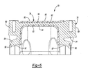
- Figure 6 is a cross-sectional view of the cover taken along line 6-6 of Figure 4 .
- Example embodiments will now be described more fully with reference to the accompanying drawings. Example embodiments are provided so that this disclosure will be thorough, and will fully convey the scope to those who are skilled in the art. Numerous specific details are set forth such as examples of specific components, devices, and methods, to provide a thorough understanding of embodiments of the present disclosure. It will be apparent to those skilled in the art that specific details need not be employed, that example embodiments may be embodied in many different forms and that neither should be construed to limit the scope of the disclosure. In some example embodiments, well-known processes, well-known device structures, and well- known technologies are not described in detail.
- first, second, third, etc. may be used herein to describe various elements, components, regions, layers and/or sections, these elements, components, regions, layers and/or sections should not be limited by these terms. These terms may be only used to distinguish one element, component, region, layer or section from another region, layer or section. Terms such as “first,” “second,” and other numerical terms when used herein do not imply a sequence or order unless clearly indicated by the context. Thus, a first element, component, region, layer or section discussed below could be termed a second element, component, region, layer or section without departing from the teachings of the example embodiments.
- a vehicle 10 is illustrated as having a drivetrain component that is constructed in accordance with the teachings of the present disclosure.
- the drivetrain component is a rear axle assembly 22, but those skilled in the art will recognize from this disclosure that the teachings of the present disclosure have application to other types of axle assemblies (e.g., front axle assemblies), as well as to other driveline components.
- the vehicle 10 can include a driveline 12 that is drivable via a connection to a power train 14.
- the power train 14 can include an engine 16 and a transmission 18.
- the driveline 12 can include a propshaft 20, the rear axle assembly 22 and a plurality of wheels 24.
- the engine 16 can be mounted in an in-line or longitudinal orientation along the axis of the vehicle 10 and its output can be selectively coupled via a conventional clutch to the input of the transmission 18 to transmit rotary power (i.e., drive torque) therebetween.
- the input of the transmission 18 can be commonly aligned with the output of the engine 16 for rotation about a rotary axis.
- the transmission 18 can also include an output and a gear reduction unit.
- the gear reduction unit can be operable for coupling the transmission input to the transmission output at a predetermined gear speed ratio.
- the propshaft 20 can be coupled for rotation with the output of the transmission 18.
- Drive torque can be transmitted through the propshaft 20 to the rear axle assembly 22 where it can be selectively apportioned in a predetermined manner to the left and right rear wheels 24a and 24b, respectively.
- the rear axle assembly 22 can include an axle housing assembly 40, a differential assembly 42, an input pinion assembly 44, and a pair of axle shafts 46.
- the differential assembly 42, the input pinion 44 and the axle shafts 46 can be generally conventional in their construction and operation, and as such, these components need not be discussed in significant detail herein.
- the input pinion 44 can be housed in the axle housing assembly 40 and can include an input shaft 120 and an input pinion 122 that can be coupled to the input shaft 120 for rotation therewith about a first axis.
- An end of the input shaft 120 opposite the input pinion 122 can be adapted to be coupled to a driveline component, such as the propshaft 20 ( Figure 1 ), to receive rotary power therefrom.
- the differential assembly 42 can be any type of differential assembly, such as an open differential assembly, a limited slip differential assembly and/or a locking differential assembly, for example.
- the differential assembly 42 can include a differential case 110, a ring gear 112, a differential gearset 114, and a pair of differential bearings 116.
- the ring gear 112 can be fixedly coupled to the differential case 110 and can be meshingly engaged with the input pinion 122 to receive rotary power therefrom.
- the differential gearset 114 can be housed in the differential case 110 and can be configured to transmit rotary power received by the differential case 110 from the ring gear 112 to the axle shafts 46.
- the differential bearings 116 can be mounted to the differential case 110 and can be configured to support the differential case 110 relative to the axle housing assembly 40 for rotation about a second axis 118 that can be perpendicular to the first axis.
- the axle shafts 46 can be employed to transmit rotary power from the outputs (e.g., side gears) of the differential gearset 114 to associated ones of the rear wheels 24a and 24b.
- the axle shafts 46 may include one or more universal joints (e.g., Cardan joints, constant velocity joints).
- the axle housing assembly 40 can include a carrier housing 54, a cover 60 and a pair of annular gaskets 115.
- the rear axle assembly 22 is configured for a rear independent suspension and as such, the axle housing assembly 40 is configured to be fixedly coupled to a vehicle chassis or sub-frame. It will be appreciated, however, that the teachings of the present disclosure have application to other types of axle assemblies, including Salisbury axle assemblies.
- the carrier housing 54 can define an internal cavity 62 that forms a fluid sump 64 in which a liquid lubricant (for lubricating the differential assembly 42 and input pinion assembly 44) is located.
- the carrier housing 54 can include a pair of bearing bulkheads 66, a pair of mounting surfaces 67, a differential aperture 68, which can be disposed on a first side of the carrier housing 54 ( Figure 3 ), and a pinion aperture 70, which can be disposed on a second side of the carrier housing 54 ( Figure 2 ) opposite the differential aperture 68.
- Each of the bearing bulkheads 66 may include an annular shoulder 71 ( Figure 3 ) and can be configured to partly receive the differential bearings 116.
- the mounting surfaces 67 can include a plurality of first apertures 72 and a plurality of second apertures 74.
- the second apertures 74 can be located on the bearing bulkheads 66.
- the differential aperture 68 can be configured to permit the differential assembly 42 to be received into the internal cavity 62.
- the pinion aperture 70 can be sized to receive the input shaft 120.
- the cover 60 can include a shell portion 76 and a bridge portion 78.
- the shell portion 76 can be molded or otherwise formed from one or more suitable materials, such as a polymer, a reinforced polymeric material, a metal, a ceramic and/or a composite material.
- the shell portion 76 is over-molded onto the bridge portion 78 such that the bridge portion 78 is cohesively bonded to and partly encased in the shell portion 76. It will be appreciated, however, that the shell portion 76 could be formed as one or more discrete components that are subsequently assembled to the bridge portion 78.
- the shell portion 76 may include a body 80 and a pair of flanges 82 that extend outward from opposite ends of the body 80.
- the body 80 may include a concave internal surface 84 ( Figures 5 and 6 ), which can face the internal cavity 62 of the carrier housing 54, and a convex external surface 86 ( Figures 4 and 6 ), which can face generally away from the carrier housing 54.
- the body 80 may span the differential aperture 68 in a first direction, such as laterally (i.e., in a direction Y as shown in Figures 3 and 4 ) such that the flanges 82 sealingly engage the mounting surfaces 67.
- Apertures 88 ( Figures 3 and 5 ) in the flanges 82 may be aligned with corresponding ones of the first apertures 72 in the mounting surfaces 67 such that fasteners 90 may be received through apertures 88 and threadably engage the first apertures 72 to secure the shell portion 76 to the carrier housing 54.
- metallic bushings 89 ( Figure 3 ) may be received in the apertures 88 and abut heads of the fasteners 90 and outward facing surfaces 91 of the flanges 82 to spread the clamp-load produced by the fasteners 90 and/or limit the clamp-load exerted by the fasteners 90 onto the flanges 82.
- the fasteners 90 may be tightened against the bushings 89 and/or flanges 82 to exert a clamping force that urges the flanges 82 into sealed engagement with the mounting surfaces 67.
- a gasket or other sealing member (neither shown) may be disposed between the flanges 82 and the mounting surfaces 67 to facilitate sealing between the flanges 82 and the mounting surfaces 67.
- the flanges 82 may directly sealingly engage the mounting surfaces 67 without a gasket or other sealing member therebetween.
- the bridge portion 78 may include a body 92 connecting a pair of bearing caps 94 that are integrally formed with the body 92.
- the bridge portion 78 may be a relatively rigid body formed from a suitable structural material, such as a reinforced plastic material, a metallic material, or a composite, for example.
- the bridge portion 78 is unitarily formed of aluminum by die casting, but those of ordinary skill in the art will appreciate from this disclosure that other metals, such as steel, iron and/or magnesium, and/or that the bridge portion 78 could be formed of several components that are fastened, welded or otherwise fixedly coupled together.
- the body 92 may be at least partially embedded in the shell portion 76, and the bearing caps 94 may extend laterally outward from the body 92 in opposite directions.
- the body 92 may be configured to maintain the bearing caps 94 in a predetermined position relative to one another and can be contoured in any manner desired.
- the body 92 is contoured to fit about the ring gear 112, and as such, includes a concave surface 93 ( Figure 6 ) that faces the internal cavity 62, and a convex surface 95 ( Figures 3 and 6 ) that faces away from the carrier housing 54.
- Reinforcing features, such as a rib 101 that extends laterally between the bearing caps 94, can be integrated into the body 92 as desired.
- each of the bearing caps 94 may include a cap portion 96, a pair of mounting bosses 98, and a sub-frame boss 99 that can engage a vehicle sub-frame (not shown).
- the cap portions 96, mounting bosses 98 and sub-frame bosses 99 may be integrally formed on the bearing caps 94.
- the cap portions 96 may include annular shoulders 97 ( Figures 5 and 6 ) facing inward toward each other.
- Mounting surfaces 100 ( Figure 5 ) may define ends of the cap portions 96 and ends of the mounting bosses 98.
- Apertures 102 may extend through the mounting bosses 98 and the mounting surfaces 100.
- the mounting bosses 98 are configured to receive fasteners 104 that are threaded into the second apertures 74 in the bearing bulkheads 66 to thereby fixedly couple the bearing caps 94 to the carrier housing 54.
- the fasteners 104 can be tightened to produce a clamp-load that is exerted onto the differential bearings 116 to secure the differential bearings 116 between the bearing bulkheads 66 and the cap portions 96.
- the clamp-load exerted by the fasteners 104 may also help to facilitate sealing between the mating mounting surfaces 67, 100.
- a gasket or other sealing member may be disposed between the mating mounting surfaces 67, 100 to help facilitate sealing therebetween.
- the bridge portion 78 and/or the shell portion 76 can include one or more locating features (not shown) configured to cooperate with mating locating features (not shown) of the carrier housing 54 to control alignment of the bearing caps 94 relative to the bearing bulkheads 66.
- the locating features of the bridge portion 78 and/or the shell portion 76 can include one or more dowel holes and the mating locating features of the carrier housing 54 can include one or more corresponding dowels. The dowel holes may be configured to receive the dowels to thereby align the bearing caps 94 to the bearing bulkheads 66.
- the annular shoulders 71, 97 of the bearing bulkheads 66 and cap portions 96, respectively, can cooperate to form counterbores.
- the annular gaskets 115 can be received into the counterbores and may abut against the annular shoulders 71, 97.
- Each set of bearing bulkheads 66 and bearing caps 94 can cooperate to define a seal mount 105 that is configured to receive a boot seal 107 ( Figure 2 ) that can create a seal between the carrier housing 54, the bearing cap 94 and an associated one of the axle shafts 46.
- the cap portions 96 of the bridge portion 78 are aligned with the bearing bulkheads 66 of the carrier housing 54. In this manner, the bridge portion 78 may span the differential aperture 68 ( Figure 3 ) in a direction X ( Figures 3 and 4 ) that is perpendicular to the direction Y.
- the body 92 of the bridge portion 78 extends between the mounting bosses 98, loads on the mounting bosses 98 due to the clamping force of the fasteners 104 and rotation of the differential assembly 42 may be transferred across the cover 60 through the body 92. This may substantially isolate the shell portion 76 from these loads, which may permit the shell portion 76 to be formed from a lighter, less rigid material that may reduce the overall weight of the cover 60 and be more conducive to forming a seal with the mounting surfaces 67 of the carrier housing 54.
- cover 60 is described above as being a part of an axle housing assembly for a rear axle assembly for a rear-wheel-drive vehicle, it will be appreciated that the principles of the present disclosure are applicable to housings and covers of other drivetrain components.
- the cover 60 could be configured for use in a front axle assembly, a transfer case assembly, a transmission housing or any other power transfer unit in rear-wheel-drive, front- wheel-drive, four-wheel-drive or all-wheel-drive vehicles.
Landscapes
- Engineering & Computer Science (AREA)
- General Engineering & Computer Science (AREA)
- Mechanical Engineering (AREA)
- General Details Of Gearings (AREA)
- Retarders (AREA)
Abstract
Description
- The present disclosure relates to a drivetrain component having a structural cover.
- This section provides background information related to the present disclosure and is not necessarily prior art.
- An axle assembly for a vehicle may include a housing having a cover. A differential may be disposed within the housing for rotation relative thereto. Design criteria for axle housings and covers may include considerations for strength, weight and seal integrity. This may be particularly true for housings and covers designed for use in cars, trucks, vans, sport-utility vehicles and/or other consumer and commercial vehicles, as owners and operators of these vehicles are increasingly demanding improved fuel economy without sacrificing performance and durability. Conventional housing covers are typically formed entirely from a metallic material to provide strength and durability.
- This section provides a general summary of the disclosure, and is not a comprehensive disclosure of its full scope or all of its features.
- In one form, the present disclosure provides a drivetrain component that may include a housing, a component, a cover and a pair of bearings. The housing may define an internal cavity and a pair of bearing bulkheads. The component may be received in the internal cavity. The cover may be coupled to the housing and may close a side of the internal cavity. The cover may include a pair of bearing caps. Each of the bearing caps may be mounted to a corresponding one of the bearing bulkheads. The pair of bearings may be received on the component. Each bearing may be engaged to an associated one of the bearing bulkheads and an associated one of the bearing caps.
- In another form, the present disclosure provides a drivetrain component that may include a carrier housing, a differential assembly and a cover. The carrier housing may include a pair of bearing bulkheads and a pair of mounting flanges. The bearing bulkheads may define a rotational axis. The mounting flanges may be disposed on opposite sides of the rotational axis such that a first one of the mounting flanges spans the bearing bulkheads on a first side of the rotational axis and a second one of the mounting flanges spans the bearing bulkheads on a second side of the rotational axis. The differential assembly may be mounted to the bearing bulkheads and may include a differential case and a pair of differential bearings mounted to the differential case. The differential bearings may be received on the bearing bulkheads. The cover may include a shell portion and a bridge portion. The shell portion may be mounted to the mounting flanges. The bridge portion may be coupled to the bearing bulkheads and may secure the differential bearings to the carrier housing.
- In yet another form, the present disclosure provides a drivetrain component that may include a carrier housing, a differential assembly and a cover. The carrier housing may include a pair of bearing bulkheads and a pair of mounting flanges. The bearing bulkheads may define a rotational axis. The mounting flanges may be disposed on opposite sides of the rotational axis such that a first one of the mounting flanges spans the bearing bulkheads on a first side of the rotational axis and a second one of the mounting flanges spans the bearing bulkheads on a second side of the rotational axis. The differential assembly may be mounted to the bearing bulkheads and may include a differential case and a pair of differential bearings mounted to the differential case. The differential bearings may be received on the bearing bulkheads. The cover may include a shell portion and a bridge portion. The shell portion may be formed of a first material including plastic that is over-molded onto the bridge portion such that at least a portion of the bridge portion is encased in and cohesively bonded to the shell portion. The shell portion may be mounted to the mounting flanges. The bridge portion may be formed of a second material including metal. The bridge portion may be coupled to the bearing bulkheads and may secure the differential bearings to the carrier housing. The bridge portion may have a mount that includes a pair of bosses. Each of the bosses may be adapted to receive a fastener therein to mount the cover to a vehicle sub- frame.
- Further areas of applicability will become apparent from the description provided herein. The description and specific examples in this summary are intended for purposes of illustration only and are not intended to limit the scope of the present disclosure.
- The drawings described herein are for illustrative purposes only of selected embodiments and not all possible implementations, and are not intended to limit the scope of the present disclosure.
-
Figure 1 is a schematic illustration of a vehicle having a rear axle assembly constructed in accordance with the teachings of the present disclosure; -
Figure 2 is a partially broken-away perspective view of a portion of the vehicle ofFigure 1 illustrating the rear axle assembly in more detail; -
Figure 3 is a partially exploded perspective view of a portion of the rear axle assembly ofFigure 2 illustrating an axle housing assembly of the rear axle assembly; -
Figure 4 is a perspective view of a portion of the axle housing assembly; -
Figure 5 is a perspective view of a portion of the rear axle assembly ofFigure 2 illustrating a cover of the axle housing assembly; and -
Figure 6 is a cross-sectional view of the cover taken along line 6-6 ofFigure 4 . - Corresponding reference numerals indicate corresponding parts throughout the several views of the drawings.
- Example embodiments will now be described more fully with reference to the accompanying drawings. Example embodiments are provided so that this disclosure will be thorough, and will fully convey the scope to those who are skilled in the art. Numerous specific details are set forth such as examples of specific components, devices, and methods, to provide a thorough understanding of embodiments of the present disclosure. It will be apparent to those skilled in the art that specific details need not be employed, that example embodiments may be embodied in many different forms and that neither should be construed to limit the scope of the disclosure. In some example embodiments, well-known processes, well-known device structures, and well- known technologies are not described in detail.
- The terminology used herein is for the purpose of describing particular example embodiments only and is not intended to be limiting. As used herein, the singular forms "a," "an," and "the" may be intended to include the plural forms as well, unless the context clearly indicates otherwise. The terms "comprises," "comprising," "including," and "having," are inclusive and therefore specify the presence of stated features, elements, and/or components, but do not preclude the presence or addition of one or more other features, elements, components, and/or groups thereof. When an element or layer is referred to as being "on," "engaged to," "connected to," or "coupled to" another element or layer, it may be directly on, engaged, connected or coupled to the other element or layer, or intervening elements or layers may be present.
- Although the terms first, second, third, etc. may be used herein to describe various elements, components, regions, layers and/or sections, these elements, components, regions, layers and/or sections should not be limited by these terms. These terms may be only used to distinguish one element, component, region, layer or section from another region, layer or section. Terms such as "first," "second," and other numerical terms when used herein do not imply a sequence or order unless clearly indicated by the context. Thus, a first element, component, region, layer or section discussed below could be termed a second element, component, region, layer or section without departing from the teachings of the example embodiments.
- With reference to
Figure 1 of the drawings, avehicle 10 is illustrated as having a drivetrain component that is constructed in accordance with the teachings of the present disclosure. In the particular example provided, the drivetrain component is arear axle assembly 22, but those skilled in the art will recognize from this disclosure that the teachings of the present disclosure have application to other types of axle assemblies (e.g., front axle assemblies), as well as to other driveline components. Thevehicle 10 can include adriveline 12 that is drivable via a connection to apower train 14. Thepower train 14 can include anengine 16 and atransmission 18. Thedriveline 12 can include apropshaft 20, therear axle assembly 22 and a plurality ofwheels 24. Theengine 16 can be mounted in an in-line or longitudinal orientation along the axis of thevehicle 10 and its output can be selectively coupled via a conventional clutch to the input of thetransmission 18 to transmit rotary power (i.e., drive torque) therebetween. The input of thetransmission 18 can be commonly aligned with the output of theengine 16 for rotation about a rotary axis. Thetransmission 18 can also include an output and a gear reduction unit. The gear reduction unit can be operable for coupling the transmission input to the transmission output at a predetermined gear speed ratio. Thepropshaft 20 can be coupled for rotation with the output of thetransmission 18. Drive torque can be transmitted through thepropshaft 20 to therear axle assembly 22 where it can be selectively apportioned in a predetermined manner to the left and rightrear wheels - With reference to
Figure 2 , therear axle assembly 22 can include anaxle housing assembly 40, adifferential assembly 42, aninput pinion assembly 44, and a pair ofaxle shafts 46. Except as described in detail herein, thedifferential assembly 42, theinput pinion 44 and theaxle shafts 46 can be generally conventional in their construction and operation, and as such, these components need not be discussed in significant detail herein. Briefly, theinput pinion 44 can be housed in theaxle housing assembly 40 and can include aninput shaft 120 and aninput pinion 122 that can be coupled to theinput shaft 120 for rotation therewith about a first axis. An end of theinput shaft 120 opposite theinput pinion 122 can be adapted to be coupled to a driveline component, such as the propshaft 20 (Figure 1 ), to receive rotary power therefrom. - The
differential assembly 42 can be any type of differential assembly, such as an open differential assembly, a limited slip differential assembly and/or a locking differential assembly, for example. Thedifferential assembly 42 can include adifferential case 110, aring gear 112, adifferential gearset 114, and a pair ofdifferential bearings 116. Thering gear 112 can be fixedly coupled to thedifferential case 110 and can be meshingly engaged with theinput pinion 122 to receive rotary power therefrom. Thedifferential gearset 114 can be housed in thedifferential case 110 and can be configured to transmit rotary power received by thedifferential case 110 from thering gear 112 to theaxle shafts 46. Thedifferential bearings 116 can be mounted to thedifferential case 110 and can be configured to support thedifferential case 110 relative to theaxle housing assembly 40 for rotation about asecond axis 118 that can be perpendicular to the first axis. Theaxle shafts 46 can be employed to transmit rotary power from the outputs (e.g., side gears) of thedifferential gearset 114 to associated ones of therear wheels axle shafts 46 may include one or more universal joints (e.g., Cardan joints, constant velocity joints). - The
axle housing assembly 40 can include acarrier housing 54, acover 60 and a pair ofannular gaskets 115. In the particular example provided, therear axle assembly 22 is configured for a rear independent suspension and as such, theaxle housing assembly 40 is configured to be fixedly coupled to a vehicle chassis or sub-frame. It will be appreciated, however, that the teachings of the present disclosure have application to other types of axle assemblies, including Salisbury axle assemblies. - With reference to
Figures 2 and3 , thecarrier housing 54 can define aninternal cavity 62 that forms afluid sump 64 in which a liquid lubricant (for lubricating thedifferential assembly 42 and input pinion assembly 44) is located. Thecarrier housing 54 can include a pair of bearingbulkheads 66, a pair of mountingsurfaces 67, adifferential aperture 68, which can be disposed on a first side of the carrier housing 54 (Figure 3 ), and apinion aperture 70, which can be disposed on a second side of the carrier housing 54 (Figure 2 ) opposite thedifferential aperture 68. Each of the bearingbulkheads 66 may include an annular shoulder 71 (Figure 3 ) and can be configured to partly receive thedifferential bearings 116. The mounting surfaces 67 can include a plurality offirst apertures 72 and a plurality ofsecond apertures 74. Thesecond apertures 74 can be located on the bearing bulkheads 66. Thedifferential aperture 68 can be configured to permit thedifferential assembly 42 to be received into theinternal cavity 62. Thepinion aperture 70 can be sized to receive theinput shaft 120. - Referring now to
Figures 3-6 , thecover 60 can include ashell portion 76 and abridge portion 78. Theshell portion 76 can be molded or otherwise formed from one or more suitable materials, such as a polymer, a reinforced polymeric material, a metal, a ceramic and/or a composite material. In the particular example provided, theshell portion 76 is over-molded onto thebridge portion 78 such that thebridge portion 78 is cohesively bonded to and partly encased in theshell portion 76. It will be appreciated, however, that theshell portion 76 could be formed as one or more discrete components that are subsequently assembled to thebridge portion 78. - The
shell portion 76 may include abody 80 and a pair offlanges 82 that extend outward from opposite ends of thebody 80. Thebody 80 may include a concave internal surface 84 (Figures 5 and6 ), which can face theinternal cavity 62 of thecarrier housing 54, and a convex external surface 86 (Figures 4 and6 ), which can face generally away from thecarrier housing 54. Thebody 80 may span thedifferential aperture 68 in a first direction, such as laterally (i.e., in a direction Y as shown inFigures 3 and4 ) such that theflanges 82 sealingly engage the mounting surfaces 67. Apertures 88 (Figures 3 and5 ) in theflanges 82 may be aligned with corresponding ones of thefirst apertures 72 in the mountingsurfaces 67 such thatfasteners 90 may be received throughapertures 88 and threadably engage thefirst apertures 72 to secure theshell portion 76 to thecarrier housing 54. In some embodiments, metallic bushings 89 (Figure 3 ) may be received in theapertures 88 and abut heads of thefasteners 90 and outward facingsurfaces 91 of theflanges 82 to spread the clamp-load produced by thefasteners 90 and/or limit the clamp-load exerted by thefasteners 90 onto theflanges 82. Thefasteners 90 may be tightened against thebushings 89 and/orflanges 82 to exert a clamping force that urges theflanges 82 into sealed engagement with the mounting surfaces 67. In some embodiments, a gasket or other sealing member (neither shown) may be disposed between theflanges 82 and the mountingsurfaces 67 to facilitate sealing between theflanges 82 and the mounting surfaces 67. In other embodiments, theflanges 82 may directly sealingly engage the mountingsurfaces 67 without a gasket or other sealing member therebetween. - With reference to
Figures 3-5 , thebridge portion 78 may include abody 92 connecting a pair of bearingcaps 94 that are integrally formed with thebody 92. Thebridge portion 78 may be a relatively rigid body formed from a suitable structural material, such as a reinforced plastic material, a metallic material, or a composite, for example. In the particular example provided, thebridge portion 78 is unitarily formed of aluminum by die casting, but those of ordinary skill in the art will appreciate from this disclosure that other metals, such as steel, iron and/or magnesium, and/or that thebridge portion 78 could be formed of several components that are fastened, welded or otherwise fixedly coupled together. - As shown in the
Figures 4-6 , thebody 92 may be at least partially embedded in theshell portion 76, and the bearing caps 94 may extend laterally outward from thebody 92 in opposite directions. Thebody 92 may be configured to maintain the bearing caps 94 in a predetermined position relative to one another and can be contoured in any manner desired. In the particular example provided, thebody 92 is contoured to fit about thering gear 112, and as such, includes a concave surface 93 (Figure 6 ) that faces theinternal cavity 62, and a convex surface 95 (Figures 3 and6 ) that faces away from thecarrier housing 54. Reinforcing features, such as arib 101 that extends laterally between the bearing caps 94, can be integrated into thebody 92 as desired. - As shown in
Figures 3-5 , each of the bearing caps 94 may include acap portion 96, a pair of mountingbosses 98, and asub-frame boss 99 that can engage a vehicle sub-frame (not shown). Thecap portions 96, mountingbosses 98 andsub-frame bosses 99 may be integrally formed on the bearing caps 94. Thecap portions 96 may include annular shoulders 97 (Figures 5 and6 ) facing inward toward each other. Mounting surfaces 100 (Figure 5 ) may define ends of thecap portions 96 and ends of the mountingbosses 98.Apertures 102 may extend through the mountingbosses 98 and the mounting surfaces 100. The mountingbosses 98 are configured to receivefasteners 104 that are threaded into thesecond apertures 74 in the bearingbulkheads 66 to thereby fixedly couple the bearing caps 94 to thecarrier housing 54. Thefasteners 104 can be tightened to produce a clamp-load that is exerted onto thedifferential bearings 116 to secure thedifferential bearings 116 between the bearingbulkheads 66 and thecap portions 96. The clamp-load exerted by thefasteners 104 may also help to facilitate sealing between themating mounting surfaces mating mounting surfaces - In some embodiments, the
bridge portion 78 and/or theshell portion 76 can include one or more locating features (not shown) configured to cooperate with mating locating features (not shown) of thecarrier housing 54 to control alignment of the bearing caps 94 relative to the bearing bulkheads 66. For example, the locating features of thebridge portion 78 and/or theshell portion 76 can include one or more dowel holes and the mating locating features of thecarrier housing 54 can include one or more corresponding dowels. The dowel holes may be configured to receive the dowels to thereby align the bearing caps 94 to the bearing bulkheads 66. - The
annular shoulders bulkheads 66 andcap portions 96, respectively, can cooperate to form counterbores. Theannular gaskets 115 can be received into the counterbores and may abut against theannular shoulders bulkheads 66 and bearing caps 94 can cooperate to define aseal mount 105 that is configured to receive a boot seal 107 (Figure 2 ) that can create a seal between thecarrier housing 54, the bearingcap 94 and an associated one of theaxle shafts 46. - When the
cover 60 is installed onto thecarrier housing 54, thecap portions 96 of thebridge portion 78 are aligned with the bearingbulkheads 66 of thecarrier housing 54. In this manner, thebridge portion 78 may span the differential aperture 68 (Figure 3 ) in a direction X (Figures 3 and4 ) that is perpendicular to the direction Y. - Because the
body 92 of thebridge portion 78 extends between the mountingbosses 98, loads on the mountingbosses 98 due to the clamping force of thefasteners 104 and rotation of thedifferential assembly 42 may be transferred across thecover 60 through thebody 92. This may substantially isolate theshell portion 76 from these loads, which may permit theshell portion 76 to be formed from a lighter, less rigid material that may reduce the overall weight of thecover 60 and be more conducive to forming a seal with the mountingsurfaces 67 of thecarrier housing 54. - While the
cover 60 is described above as being a part of an axle housing assembly for a rear axle assembly for a rear-wheel-drive vehicle, it will be appreciated that the principles of the present disclosure are applicable to housings and covers of other drivetrain components. For example, thecover 60 could be configured for use in a front axle assembly, a transfer case assembly, a transmission housing or any other power transfer unit in rear-wheel-drive, front- wheel-drive, four-wheel-drive or all-wheel-drive vehicles. - The foregoing description of the embodiments has been provided for purposes of illustration and description. It is not intended to be exhaustive or to limit the disclosure. Individual elements or features of a particular embodiment are generally not limited to that particular embodiment, but, where applicable, are interchangeable and can be used in a selected embodiment, even if not specifically shown or described. The same may also be varied in many ways. Such variations are not to be regarded as a departure from the disclosure, and all such modifications are intended to be included within the scope of the disclosure.
Claims (11)
- A drivetrain component (22) comprising:a housing (54) defining an internal cavity (62) and a pair of bearing bulkheads (66);a component (110) received in the internal cavity (62);a cover (60) coupled to the housing (54) and closing a side of the internal cavity (62); anda pair of bearings (116) received on the component (110), each bearing (116) being engaged to an associated one of the bearing bulkheads (66) and an associated one of the bearing caps (94),the drivetrain component (22) characterized in that the cover (60) includes a pair of bearing caps (94), each of the bearing caps being mounted to a corresponding one of the bearing bulkheads (66) and wherein the cover (60) comprises a shell portion (76) and a bridge portion (78) that are formed of different materials.
- The drivetrain component (22) of Claim 1, wherein the bearing caps (94) are integrally formed with the bridge portion (78).
- The drivetrain component (22) of Claim 1, wherein the shell portion (76) is formed of plastic and wherein the bridge portion (78) is formed of metal.
- The drivetrain component (22) of Claim 1, wherein the shell portion (76) is cohesively bonded to the bridge portion (78).
- The drivetrain component (22) of Claim 1, wherein the bridge portion (78) is at least partly encased in the shell portion (76).
- The drivetrain component (22) of Claim 1, wherein the component (110) is a differential case (110).
- The drivetrain component (22) of Claim 6, wherein a differential gearset (114) is received in the differential case (110) and wherein a pair of shafts (46) are coupled to output members of the differential gearset (114) for rotation therewith.
- The drivetrain component (22) of Claim 1, wherein a shoulder (71, 97) is formed into each pair of the bearing bulkheads (66) and the bearing caps (94), and wherein a gasket (115) is received against each shoulder (71, 97).
- The drivetrain component (22) of Claim 1, wherein the cover (60) includes a mount (99) that is adapted to mount the drivetrain component (22) to a frame.
- The drivetrain component (22) of Claim 9, wherein the mount (99) comprises at least one boss (99) that is configured to receive a fastener.
- The drivetrain component (22) of Claim 10, wherein the mount (99) comprises two bosses (99), each boss (99) being fixedly coupled to a corresponding one of the bearing caps (94).
Applications Claiming Priority (1)
| Application Number | Priority Date | Filing Date | Title |
|---|---|---|---|
| US13/613,435 US8657716B1 (en) | 2012-09-13 | 2012-09-13 | Drive train component with structural cover |
Publications (2)
| Publication Number | Publication Date |
|---|---|
| EP2708776A1 true EP2708776A1 (en) | 2014-03-19 |
| EP2708776B1 EP2708776B1 (en) | 2017-11-01 |
Family
ID=49212583
Family Applications (1)
| Application Number | Title | Priority Date | Filing Date |
|---|---|---|---|
| EP13184056.3A Not-in-force EP2708776B1 (en) | 2012-09-13 | 2013-09-12 | Drive train component with structural cover |
Country Status (2)
| Country | Link |
|---|---|
| US (1) | US8657716B1 (en) |
| EP (1) | EP2708776B1 (en) |
Cited By (1)
| Publication number | Priority date | Publication date | Assignee | Title |
|---|---|---|---|---|
| WO2018060079A1 (en) * | 2016-09-29 | 2018-04-05 | Jaguar Land Rover Limited | A drive assembly for a vehicle |
Families Citing this family (14)
| Publication number | Priority date | Publication date | Assignee | Title |
|---|---|---|---|---|
| USD741913S1 (en) | 2013-06-05 | 2015-10-27 | Eaton Corporation | Integrated electronic limited slip rear wheel drive axle cover |
| US9022892B1 (en) | 2014-04-23 | 2015-05-05 | American Axle & Manufacturing, Inc. | Axle assembly having differential assembly with inverted differential bearings |
| US10279625B2 (en) * | 2014-08-15 | 2019-05-07 | Arvinmeritor Technology, Llc | Axel assembly having a bowl cover and a method of manufacture |
| US9919559B2 (en) * | 2014-12-11 | 2018-03-20 | Ford Global Technologies, Llc | Axle carrier housing with a swept support rib |
| CN204368366U (en) * | 2015-01-06 | 2015-06-03 | 好孩子儿童用品有限公司 | A kind of children's drift car |
| US9651136B2 (en) * | 2015-04-01 | 2017-05-16 | Borgwarner Inc. | Transfer case with aluminum yoke |
| USD798906S1 (en) | 2015-11-02 | 2017-10-03 | Omix-Ada, Inc. | Vehicle differential cover |
| US9835239B2 (en) * | 2016-01-21 | 2017-12-05 | General Electric Company | Composite gearbox housing |
| US20170356536A1 (en) * | 2016-06-09 | 2017-12-14 | Dana Automotive Systems Group, Llc | Lightweight and narrow differential assembly with powder metal inserts |
| US11512770B2 (en) | 2016-10-10 | 2022-11-29 | Ratier-Figeac Sas | Gearbox assembly |
| EP3306137A1 (en) * | 2016-10-10 | 2018-04-11 | Ratier-Figeac SAS | Gearbox assembly providing redundancy |
| GB2557985A (en) * | 2016-12-21 | 2018-07-04 | Ricardo Uk Ltd | Differential gear assembly and method of assembly |
| US10436307B2 (en) * | 2017-02-27 | 2019-10-08 | GM Global Technology Operations LLC | Composite axle housing and methods of manufacturing thereof |
| DE102021213292A1 (en) | 2021-11-25 | 2023-05-25 | Zf Friedrichshafen Ag | Transmission housing with a load-bearing housing body and an unloaded housing cover, and transmission and drive assembly with the transmission housing |
Citations (4)
| Publication number | Priority date | Publication date | Assignee | Title |
|---|---|---|---|---|
| US5156576A (en) * | 1991-05-22 | 1992-10-20 | Sauer, Inc. | Compact integrated transaxle |
| US5279186A (en) * | 1992-12-18 | 1994-01-18 | Chrysler Corporation | Assembly for a north-south automatic transaxle |
| US6105463A (en) * | 1997-07-24 | 2000-08-22 | Hydro-Gear Limited Partnership | Transmission and transaxle casing |
| EP2078632A2 (en) * | 2008-01-11 | 2009-07-15 | Kanzaki Kokyukoki Mfg. Co., Ltd. | Hydrostatic transaxle |
Family Cites Families (35)
| Publication number | Priority date | Publication date | Assignee | Title |
|---|---|---|---|---|
| US1211673A (en) * | 1915-06-03 | 1917-01-09 | Baush Machine Tool Company | Driving mechanism for motor-vehicles. |
| US2015969A (en) | 1932-03-26 | 1935-10-01 | Daimler Benz Ag | Rear axle gear casing |
| US1944612A (en) * | 1932-08-10 | 1934-01-23 | Repeck Frank | Differential carrier |
| US4234120A (en) | 1978-04-06 | 1980-11-18 | United States Steel Corporation | Axle housing assembly |
| JPS5812658U (en) | 1981-07-16 | 1983-01-26 | 日産自動車株式会社 | Rotsuka cover |
| US5271294A (en) | 1992-05-08 | 1993-12-21 | Dana Corporation | Banjo type axle housing having differential carrier support structure |
| US5476582A (en) | 1993-07-19 | 1995-12-19 | Camping; Paul C. | Filter cover assembly for differential housing mechanism |
| US5839327A (en) | 1995-09-18 | 1998-11-24 | American Axle & Manufacturing, Inc. | Drive axle assembly with lubricant cooling system |
| US6189413B1 (en) | 1999-07-12 | 2001-02-20 | American Axle & Manufacturing, Inc. | Captive molding with dissimilar material insert |
| US6796404B1 (en) | 2000-03-22 | 2004-09-28 | American Axle & Manufacturing, Inc. | Cover pan ABS sensor |
| US6398689B1 (en) * | 2000-03-27 | 2002-06-04 | American Axle & Manufacturing, Inc. | One piece differential bearing adjuster lock and fastener |
| US6553865B1 (en) | 2000-08-31 | 2003-04-29 | American Axle & Manufacturing, Inc. | Cover pan mounted vent connector |
| US7829006B2 (en) * | 2001-02-15 | 2010-11-09 | Integral Technologies, Inc. | Method to form vehicle component devices from conductive loaded resin-based materials |
| US20020134194A1 (en) | 2001-03-21 | 2002-09-26 | Milio Raymond A. | Axle housing cover with variable thickness |
| US6623867B2 (en) | 2001-07-13 | 2003-09-23 | Visteon Global Technologies, Inc. | Reinforced aluminum metal composite carrier |
| US6675676B2 (en) | 2001-12-14 | 2004-01-13 | Americam Axle & Manufacturing, Inc. | Differential cover for a vehicle that provides uniform sealing |
| US6729207B2 (en) | 2002-03-20 | 2004-05-04 | Torque-Traction Technologies, Inc. | Rigid drive axle assembly for motor vehicles |
| US20060054411A1 (en) | 2002-05-14 | 2006-03-16 | Fett Gregory A | Heat pipe cooler for differential assembly |
| US7669330B1 (en) | 2002-06-07 | 2010-03-02 | Mcgean Jim | Method for structuring a gear assembly housing |
| US6813972B2 (en) | 2002-08-07 | 2004-11-09 | Visteon Global Technologies, Inc. | Differential housing assembly with cap-ring bearing support architecture |
| US20040216556A1 (en) * | 2003-04-30 | 2004-11-04 | Smith Todd A. | Composite differential carrier having cage-type differential carrier frame member |
| US7140969B2 (en) | 2003-08-22 | 2006-11-28 | American Axle & Manufacturing, Inc. | Overmolded yoke assembly |
| US7121972B2 (en) | 2003-10-30 | 2006-10-17 | Torque-Traction Technologies, Inc. | Adjustable flange device for cover member in drive axle assembly |
| US7155827B2 (en) * | 2003-10-30 | 2007-01-02 | Torque-Traction Technologies, Llc. | Method for verifying predetermined bearing preload of differential assembly module |
| US7077778B1 (en) * | 2003-12-03 | 2006-07-18 | Koji Irikura | Bull gear of differential gear assembly |
| US7004879B2 (en) | 2004-01-12 | 2006-02-28 | American Axle & Manufacturing, Inc. | Axle differential with stamped carrier cover pan |
| US7241246B2 (en) | 2004-11-18 | 2007-07-10 | American Axle & Manufacturing, Inc. | Differential assembly with cover gasket having integral magnet |
| US7231847B2 (en) | 2005-03-28 | 2007-06-19 | American Axle & Manufacturing, Inc. | Axle assembly with threaded cover pan attachment and method of assembly |
| US7610893B2 (en) | 2006-02-10 | 2009-11-03 | Federal-Mogul Worldwide, Inc. | Plastic cover having metal reinforcement for internal combustion engine applications and method of construction |
| US8109000B2 (en) * | 2007-05-31 | 2012-02-07 | American Axle & Manufacturing, Inc. | Salisbury axle assembly |
| US7819769B2 (en) * | 2007-06-18 | 2010-10-26 | American Axle & Manufacturing, Inc. | Vehicle driveline component having heat sink for increased heat rejection capabilities |
| US20090071287A1 (en) | 2007-09-13 | 2009-03-19 | Adam Paskowitz | External differential cover for vehicles |
| US8109174B2 (en) | 2008-08-22 | 2012-02-07 | American Axle & Manufacturing, Inc. | Differential cover providing lubricant flow control |
| US8152382B2 (en) | 2009-01-23 | 2012-04-10 | Dana Heavy Vehicle Systems Group, Llc | Output tube assembly for drive axle covers and method of use |
| US8499664B2 (en) | 2009-09-25 | 2013-08-06 | Caterpillar Inc. | Axle shaft cover plate with bearing assembly |
-
2012
- 2012-09-13 US US13/613,435 patent/US8657716B1/en active Active
-
2013
- 2013-09-12 EP EP13184056.3A patent/EP2708776B1/en not_active Not-in-force
Patent Citations (5)
| Publication number | Priority date | Publication date | Assignee | Title |
|---|---|---|---|---|
| US5156576A (en) * | 1991-05-22 | 1992-10-20 | Sauer, Inc. | Compact integrated transaxle |
| US5156576B1 (en) * | 1991-05-22 | 1994-08-30 | Sauer Inc | Compact integrated transaxle |
| US5279186A (en) * | 1992-12-18 | 1994-01-18 | Chrysler Corporation | Assembly for a north-south automatic transaxle |
| US6105463A (en) * | 1997-07-24 | 2000-08-22 | Hydro-Gear Limited Partnership | Transmission and transaxle casing |
| EP2078632A2 (en) * | 2008-01-11 | 2009-07-15 | Kanzaki Kokyukoki Mfg. Co., Ltd. | Hydrostatic transaxle |
Cited By (2)
| Publication number | Priority date | Publication date | Assignee | Title |
|---|---|---|---|---|
| WO2018060079A1 (en) * | 2016-09-29 | 2018-04-05 | Jaguar Land Rover Limited | A drive assembly for a vehicle |
| GB2554450B (en) * | 2016-09-29 | 2020-01-15 | Jaguar Land Rover Ltd | A drive assembly for a vehicle |
Also Published As
| Publication number | Publication date |
|---|---|
| US20140073471A1 (en) | 2014-03-13 |
| US8657716B1 (en) | 2014-02-25 |
| EP2708776B1 (en) | 2017-11-01 |
Similar Documents
| Publication | Publication Date | Title |
|---|---|---|
| US8657716B1 (en) | Drive train component with structural cover | |
| US7866231B2 (en) | Axle assembly having gasket that shields an opening | |
| EP1553330B1 (en) | Axle differential with stamped carrier cover pan | |
| CN103629325B (en) | Aluminium flange with anti-rotational groove | |
| WO2009088798A2 (en) | Differential assembly with oil deflector shield | |
| US20110082001A1 (en) | Vehicle driveline component having heat sink for increased heat rejection capabilities | |
| KR20170030431A (en) | Aluminum differential housing with cast iron inserts | |
| US7819769B2 (en) | Vehicle driveline component having heat sink for increased heat rejection capabilities | |
| CN113183754A (en) | Spline sealing connection system of electric drive axle assembly | |
| US8142292B2 (en) | Universal joint with trunnion shaft seal assembly | |
| US20210284016A1 (en) | Center bearing bracket assembly | |
| US10871218B2 (en) | Injection molded retention method for power transfer devices | |
| EP3305573B1 (en) | Vehicular power transmission device | |
| US20230167782A1 (en) | Cylinder block for engine | |
| US7004277B2 (en) | Power blocks | |
| KR20140069451A (en) | Coupling structure of propeller shaft in vehicle | |
| JP4828847B2 (en) | Differential equipment | |
| CN101644301B (en) | Vehicle joint design utilizing bipode element | |
| EP4062085B1 (en) | Transmission assembly for a powertrain of a vehicle | |
| CN103883636B (en) | A kind of cardan universal joint component | |
| US20200088240A1 (en) | A joint assembly with an installation aid | |
| JP3751038B2 (en) | Automotive propulsion shaft coupling device | |
| US12092191B1 (en) | Torque vector multiplier | |
| CN216886099U (en) | Axle assembly | |
| CN216715152U (en) | Differential mechanism, drive axle assembly and vehicle |
Legal Events
| Date | Code | Title | Description |
|---|---|---|---|
| PUAI | Public reference made under article 153(3) epc to a published international application that has entered the european phase |
Free format text: ORIGINAL CODE: 0009012 |
|
| AK | Designated contracting states |
Kind code of ref document: A1 Designated state(s): AL AT BE BG CH CY CZ DE DK EE ES FI FR GB GR HR HU IE IS IT LI LT LU LV MC MK MT NL NO PL PT RO RS SE SI SK SM TR |
|
| AX | Request for extension of the european patent |
Extension state: BA ME |
|
| 17P | Request for examination filed |
Effective date: 20140912 |
|
| RBV | Designated contracting states (corrected) |
Designated state(s): AL AT BE BG CH CY CZ DE DK EE ES FI FR GB GR HR HU IE IS IT LI LT LU LV MC MK MT NL NO PL PT RO RS SE SI SK SM TR |
|
| 17Q | First examination report despatched |
Effective date: 20150205 |
|
| GRAP | Despatch of communication of intention to grant a patent |
Free format text: ORIGINAL CODE: EPIDOSNIGR1 |
|
| INTG | Intention to grant announced |
Effective date: 20170523 |
|
| GRAS | Grant fee paid |
Free format text: ORIGINAL CODE: EPIDOSNIGR3 |
|
| GRAA | (expected) grant |
Free format text: ORIGINAL CODE: 0009210 |
|
| AK | Designated contracting states |
Kind code of ref document: B1 Designated state(s): AL AT BE BG CH CY CZ DE DK EE ES FI FR GB GR HR HU IE IS IT LI LT LU LV MC MK MT NL NO PL PT RO RS SE SI SK SM TR |
|
| REG | Reference to a national code |
Ref country code: GB Ref legal event code: FG4D |
|
| REG | Reference to a national code |
Ref country code: CH Ref legal event code: EP Ref country code: AT Ref legal event code: REF Ref document number: 942364 Country of ref document: AT Kind code of ref document: T Effective date: 20171115 |
|
| REG | Reference to a national code |
Ref country code: IE Ref legal event code: FG4D |
|
| REG | Reference to a national code |
Ref country code: DE Ref legal event code: R096 Ref document number: 602013028662 Country of ref document: DE |
|
| REG | Reference to a national code |
Ref country code: NL Ref legal event code: MP Effective date: 20171101 |
|
| REG | Reference to a national code |
Ref country code: LT Ref legal event code: MG4D |
|
| REG | Reference to a national code |
Ref country code: AT Ref legal event code: MK05 Ref document number: 942364 Country of ref document: AT Kind code of ref document: T Effective date: 20171101 |
|
| PG25 | Lapsed in a contracting state [announced via postgrant information from national office to epo] |
Ref country code: NO Free format text: LAPSE BECAUSE OF FAILURE TO SUBMIT A TRANSLATION OF THE DESCRIPTION OR TO PAY THE FEE WITHIN THE PRESCRIBED TIME-LIMIT Effective date: 20180201 Ref country code: FI Free format text: LAPSE BECAUSE OF FAILURE TO SUBMIT A TRANSLATION OF THE DESCRIPTION OR TO PAY THE FEE WITHIN THE PRESCRIBED TIME-LIMIT Effective date: 20171101 Ref country code: NL Free format text: LAPSE BECAUSE OF FAILURE TO SUBMIT A TRANSLATION OF THE DESCRIPTION OR TO PAY THE FEE WITHIN THE PRESCRIBED TIME-LIMIT Effective date: 20171101 Ref country code: LT Free format text: LAPSE BECAUSE OF FAILURE TO SUBMIT A TRANSLATION OF THE DESCRIPTION OR TO PAY THE FEE WITHIN THE PRESCRIBED TIME-LIMIT Effective date: 20171101 Ref country code: ES Free format text: LAPSE BECAUSE OF FAILURE TO SUBMIT A TRANSLATION OF THE DESCRIPTION OR TO PAY THE FEE WITHIN THE PRESCRIBED TIME-LIMIT Effective date: 20171101 Ref country code: SE Free format text: LAPSE BECAUSE OF FAILURE TO SUBMIT A TRANSLATION OF THE DESCRIPTION OR TO PAY THE FEE WITHIN THE PRESCRIBED TIME-LIMIT Effective date: 20171101 |
|
| PG25 | Lapsed in a contracting state [announced via postgrant information from national office to epo] |
Ref country code: AT Free format text: LAPSE BECAUSE OF FAILURE TO SUBMIT A TRANSLATION OF THE DESCRIPTION OR TO PAY THE FEE WITHIN THE PRESCRIBED TIME-LIMIT Effective date: 20171101 Ref country code: RS Free format text: LAPSE BECAUSE OF FAILURE TO SUBMIT A TRANSLATION OF THE DESCRIPTION OR TO PAY THE FEE WITHIN THE PRESCRIBED TIME-LIMIT Effective date: 20171101 Ref country code: BG Free format text: LAPSE BECAUSE OF FAILURE TO SUBMIT A TRANSLATION OF THE DESCRIPTION OR TO PAY THE FEE WITHIN THE PRESCRIBED TIME-LIMIT Effective date: 20180201 Ref country code: GR Free format text: LAPSE BECAUSE OF FAILURE TO SUBMIT A TRANSLATION OF THE DESCRIPTION OR TO PAY THE FEE WITHIN THE PRESCRIBED TIME-LIMIT Effective date: 20180202 Ref country code: IS Free format text: LAPSE BECAUSE OF FAILURE TO SUBMIT A TRANSLATION OF THE DESCRIPTION OR TO PAY THE FEE WITHIN THE PRESCRIBED TIME-LIMIT Effective date: 20180301 Ref country code: HR Free format text: LAPSE BECAUSE OF FAILURE TO SUBMIT A TRANSLATION OF THE DESCRIPTION OR TO PAY THE FEE WITHIN THE PRESCRIBED TIME-LIMIT Effective date: 20171101 Ref country code: LV Free format text: LAPSE BECAUSE OF FAILURE TO SUBMIT A TRANSLATION OF THE DESCRIPTION OR TO PAY THE FEE WITHIN THE PRESCRIBED TIME-LIMIT Effective date: 20171101 |
|
| PG25 | Lapsed in a contracting state [announced via postgrant information from national office to epo] |
Ref country code: CZ Free format text: LAPSE BECAUSE OF FAILURE TO SUBMIT A TRANSLATION OF THE DESCRIPTION OR TO PAY THE FEE WITHIN THE PRESCRIBED TIME-LIMIT Effective date: 20171101 Ref country code: SK Free format text: LAPSE BECAUSE OF FAILURE TO SUBMIT A TRANSLATION OF THE DESCRIPTION OR TO PAY THE FEE WITHIN THE PRESCRIBED TIME-LIMIT Effective date: 20171101 Ref country code: DK Free format text: LAPSE BECAUSE OF FAILURE TO SUBMIT A TRANSLATION OF THE DESCRIPTION OR TO PAY THE FEE WITHIN THE PRESCRIBED TIME-LIMIT Effective date: 20171101 Ref country code: CY Free format text: LAPSE BECAUSE OF FAILURE TO SUBMIT A TRANSLATION OF THE DESCRIPTION OR TO PAY THE FEE WITHIN THE PRESCRIBED TIME-LIMIT Effective date: 20171101 Ref country code: EE Free format text: LAPSE BECAUSE OF FAILURE TO SUBMIT A TRANSLATION OF THE DESCRIPTION OR TO PAY THE FEE WITHIN THE PRESCRIBED TIME-LIMIT Effective date: 20171101 |
|
| REG | Reference to a national code |
Ref country code: DE Ref legal event code: R097 Ref document number: 602013028662 Country of ref document: DE |
|
| PG25 | Lapsed in a contracting state [announced via postgrant information from national office to epo] |
Ref country code: IT Free format text: LAPSE BECAUSE OF FAILURE TO SUBMIT A TRANSLATION OF THE DESCRIPTION OR TO PAY THE FEE WITHIN THE PRESCRIBED TIME-LIMIT Effective date: 20171101 Ref country code: RO Free format text: LAPSE BECAUSE OF FAILURE TO SUBMIT A TRANSLATION OF THE DESCRIPTION OR TO PAY THE FEE WITHIN THE PRESCRIBED TIME-LIMIT Effective date: 20171101 Ref country code: PL Free format text: LAPSE BECAUSE OF FAILURE TO SUBMIT A TRANSLATION OF THE DESCRIPTION OR TO PAY THE FEE WITHIN THE PRESCRIBED TIME-LIMIT Effective date: 20171101 Ref country code: SM Free format text: LAPSE BECAUSE OF FAILURE TO SUBMIT A TRANSLATION OF THE DESCRIPTION OR TO PAY THE FEE WITHIN THE PRESCRIBED TIME-LIMIT Effective date: 20171101 |
|
| PLBE | No opposition filed within time limit |
Free format text: ORIGINAL CODE: 0009261 |
|
| STAA | Information on the status of an ep patent application or granted ep patent |
Free format text: STATUS: NO OPPOSITION FILED WITHIN TIME LIMIT |
|
| 26N | No opposition filed |
Effective date: 20180802 |
|
| PG25 | Lapsed in a contracting state [announced via postgrant information from national office to epo] |
Ref country code: SI Free format text: LAPSE BECAUSE OF FAILURE TO SUBMIT A TRANSLATION OF THE DESCRIPTION OR TO PAY THE FEE WITHIN THE PRESCRIBED TIME-LIMIT Effective date: 20171101 |
|
| PG25 | Lapsed in a contracting state [announced via postgrant information from national office to epo] |
Ref country code: MC Free format text: LAPSE BECAUSE OF FAILURE TO SUBMIT A TRANSLATION OF THE DESCRIPTION OR TO PAY THE FEE WITHIN THE PRESCRIBED TIME-LIMIT Effective date: 20171101 |
|
| REG | Reference to a national code |
Ref country code: CH Ref legal event code: PL |
|
| REG | Reference to a national code |
Ref country code: BE Ref legal event code: MM Effective date: 20180930 |
|
| REG | Reference to a national code |
Ref country code: IE Ref legal event code: MM4A |
|
| PG25 | Lapsed in a contracting state [announced via postgrant information from national office to epo] |
Ref country code: LU Free format text: LAPSE BECAUSE OF NON-PAYMENT OF DUE FEES Effective date: 20180912 |
|
| PG25 | Lapsed in a contracting state [announced via postgrant information from national office to epo] |
Ref country code: IE Free format text: LAPSE BECAUSE OF NON-PAYMENT OF DUE FEES Effective date: 20180912 |
|
| PG25 | Lapsed in a contracting state [announced via postgrant information from national office to epo] |
Ref country code: LI Free format text: LAPSE BECAUSE OF NON-PAYMENT OF DUE FEES Effective date: 20180930 Ref country code: BE Free format text: LAPSE BECAUSE OF NON-PAYMENT OF DUE FEES Effective date: 20180930 Ref country code: FR Free format text: LAPSE BECAUSE OF NON-PAYMENT OF DUE FEES Effective date: 20180930 Ref country code: CH Free format text: LAPSE BECAUSE OF NON-PAYMENT OF DUE FEES Effective date: 20180930 |
|
| PG25 | Lapsed in a contracting state [announced via postgrant information from national office to epo] |
Ref country code: MT Free format text: LAPSE BECAUSE OF NON-PAYMENT OF DUE FEES Effective date: 20180912 |
|
| PG25 | Lapsed in a contracting state [announced via postgrant information from national office to epo] |
Ref country code: TR Free format text: LAPSE BECAUSE OF FAILURE TO SUBMIT A TRANSLATION OF THE DESCRIPTION OR TO PAY THE FEE WITHIN THE PRESCRIBED TIME-LIMIT Effective date: 20171101 |
|
| PG25 | Lapsed in a contracting state [announced via postgrant information from national office to epo] |
Ref country code: PT Free format text: LAPSE BECAUSE OF FAILURE TO SUBMIT A TRANSLATION OF THE DESCRIPTION OR TO PAY THE FEE WITHIN THE PRESCRIBED TIME-LIMIT Effective date: 20171101 Ref country code: HU Free format text: LAPSE BECAUSE OF FAILURE TO SUBMIT A TRANSLATION OF THE DESCRIPTION OR TO PAY THE FEE WITHIN THE PRESCRIBED TIME-LIMIT; INVALID AB INITIO Effective date: 20130912 |
|
| PG25 | Lapsed in a contracting state [announced via postgrant information from national office to epo] |
Ref country code: MK Free format text: LAPSE BECAUSE OF NON-PAYMENT OF DUE FEES Effective date: 20171101 |
|
| PG25 | Lapsed in a contracting state [announced via postgrant information from national office to epo] |
Ref country code: AL Free format text: LAPSE BECAUSE OF FAILURE TO SUBMIT A TRANSLATION OF THE DESCRIPTION OR TO PAY THE FEE WITHIN THE PRESCRIBED TIME-LIMIT Effective date: 20171101 |
|
| REG | Reference to a national code |
Ref country code: DE Ref legal event code: R082 Ref document number: 602013028662 Country of ref document: DE Representative=s name: BIRD & BIRD LLP, DE |
|
| PGFP | Annual fee paid to national office [announced via postgrant information from national office to epo] |
Ref country code: GB Payment date: 20230920 Year of fee payment: 11 |
|
| PGFP | Annual fee paid to national office [announced via postgrant information from national office to epo] |
Ref country code: DE Payment date: 20230920 Year of fee payment: 11 |
|
| REG | Reference to a national code |
Ref country code: DE Ref legal event code: R119 Ref document number: 602013028662 Country of ref document: DE |
|
| GBPC | Gb: european patent ceased through non-payment of renewal fee |
Effective date: 20240912 |
|
| PG25 | Lapsed in a contracting state [announced via postgrant information from national office to epo] |
Ref country code: DE Free format text: LAPSE BECAUSE OF NON-PAYMENT OF DUE FEES Effective date: 20250401 |
|
| PG25 | Lapsed in a contracting state [announced via postgrant information from national office to epo] |
Ref country code: GB Free format text: LAPSE BECAUSE OF NON-PAYMENT OF DUE FEES Effective date: 20240912 |