EP2708572A1 - UV Curing System and Method for Wind Blade Manufacture and Repair - Google Patents
UV Curing System and Method for Wind Blade Manufacture and Repair Download PDFInfo
- Publication number
- EP2708572A1 EP2708572A1 EP20130183940 EP13183940A EP2708572A1 EP 2708572 A1 EP2708572 A1 EP 2708572A1 EP 20130183940 EP20130183940 EP 20130183940 EP 13183940 A EP13183940 A EP 13183940A EP 2708572 A1 EP2708572 A1 EP 2708572A1
- Authority
- EP
- European Patent Office
- Prior art keywords
- vinyl ester
- resin
- composition
- curable
- mixtures
- Prior art date
- Legal status (The legal status is an assumption and is not a legal conclusion. Google has not performed a legal analysis and makes no representation as to the accuracy of the status listed.)
- Withdrawn
Links
- 238000000034 method Methods 0.000 title claims abstract description 73
- 238000004519 manufacturing process Methods 0.000 title claims abstract description 33
- 230000008439 repair process Effects 0.000 title abstract description 32
- 238000003848 UV Light-Curing Methods 0.000 title abstract description 14
- 230000005855 radiation Effects 0.000 claims abstract description 54
- CEXQWAAGPPNOQF-UHFFFAOYSA-N 2-phenoxyethyl 2-methylprop-2-enoate Chemical compound CC(=C)C(=O)OCCOC1=CC=CC=C1 CEXQWAAGPPNOQF-UHFFFAOYSA-N 0.000 claims abstract description 11
- 239000000203 mixture Substances 0.000 claims description 97
- 229920005989 resin Polymers 0.000 claims description 68
- 239000011347 resin Substances 0.000 claims description 68
- 229920006241 epoxy vinyl ester resin Polymers 0.000 claims description 33
- 229920001567 vinyl ester resin Polymers 0.000 claims description 24
- 239000004744 fabric Substances 0.000 claims description 21
- -1 acryl halides Chemical class 0.000 claims description 17
- 239000011521 glass Substances 0.000 claims description 14
- 229910017052 cobalt Inorganic materials 0.000 claims description 13
- 239000010941 cobalt Substances 0.000 claims description 13
- 239000000805 composite resin Substances 0.000 claims description 13
- 150000004982 aromatic amines Chemical class 0.000 claims description 12
- GUTLYIVDDKVIGB-UHFFFAOYSA-N cobalt atom Chemical group [Co] GUTLYIVDDKVIGB-UHFFFAOYSA-N 0.000 claims description 11
- 239000002318 adhesion promoter Substances 0.000 claims description 8
- 239000000945 filler Substances 0.000 claims description 8
- JLTDJTHDQAWBAV-UHFFFAOYSA-N N,N-dimethylaniline Chemical compound CN(C)C1=CC=CC=C1 JLTDJTHDQAWBAV-UHFFFAOYSA-N 0.000 claims description 7
- 229920000647 polyepoxide Polymers 0.000 claims description 7
- MMEDJBFVJUFIDD-UHFFFAOYSA-N 2-[2-(carboxymethyl)phenyl]acetic acid Chemical compound OC(=O)CC1=CC=CC=C1CC(O)=O MMEDJBFVJUFIDD-UHFFFAOYSA-N 0.000 claims description 6
- UFWIBTONFRDIAS-UHFFFAOYSA-N Naphthalene Chemical compound C1=CC=CC2=CC=CC=C21 UFWIBTONFRDIAS-UHFFFAOYSA-N 0.000 claims description 6
- IISBACLAFKSPIT-UHFFFAOYSA-N bisphenol A Chemical compound C=1C=C(O)C=CC=1C(C)(C)C1=CC=C(O)C=C1 IISBACLAFKSPIT-UHFFFAOYSA-N 0.000 claims description 6
- PXKLMJQFEQBVLD-UHFFFAOYSA-N bisphenol F Chemical compound C1=CC(O)=CC=C1CC1=CC=C(O)C=C1 PXKLMJQFEQBVLD-UHFFFAOYSA-N 0.000 claims description 6
- 150000001875 compounds Chemical class 0.000 claims description 6
- GGSUCNLOZRCGPQ-UHFFFAOYSA-N diethylaniline Chemical compound CCN(CC)C1=CC=CC=C1 GGSUCNLOZRCGPQ-UHFFFAOYSA-N 0.000 claims description 6
- ZUOUZKKEUPVFJK-UHFFFAOYSA-N diphenyl Chemical compound C1=CC=CC=C1C1=CC=CC=C1 ZUOUZKKEUPVFJK-UHFFFAOYSA-N 0.000 claims description 6
- 229920003986 novolac Polymers 0.000 claims description 6
- 230000002787 reinforcement Effects 0.000 claims description 6
- 239000002184 metal Substances 0.000 claims description 5
- 229910052751 metal Inorganic materials 0.000 claims description 5
- 150000008062 acetophenones Chemical class 0.000 claims description 4
- 125000003118 aryl group Chemical group 0.000 claims description 4
- WURBFLDFSFBTLW-UHFFFAOYSA-N benzil Chemical compound C=1C=CC=CC=1C(=O)C(=O)C1=CC=CC=C1 WURBFLDFSFBTLW-UHFFFAOYSA-N 0.000 claims description 4
- 125000003236 benzoyl group Chemical group [H]C1=C([H])C([H])=C(C([H])=C1[H])C(*)=O 0.000 claims description 4
- 150000007942 carboxylates Chemical class 0.000 claims description 4
- 239000003822 epoxy resin Substances 0.000 claims description 4
- AUONHKJOIZSQGR-UHFFFAOYSA-N oxophosphane Chemical compound P=O AUONHKJOIZSQGR-UHFFFAOYSA-N 0.000 claims description 4
- HSOOIVBINKDISP-UHFFFAOYSA-N 1-(2-methylprop-2-enoyloxy)butyl 2-methylprop-2-enoate Chemical compound CC(=C)C(=O)OC(CCC)OC(=O)C(C)=C HSOOIVBINKDISP-UHFFFAOYSA-N 0.000 claims description 3
- OGBWMWKMTUSNKE-UHFFFAOYSA-N 1-(2-methylprop-2-enoyloxy)hexyl 2-methylprop-2-enoate Chemical compound CCCCCC(OC(=O)C(C)=C)OC(=O)C(C)=C OGBWMWKMTUSNKE-UHFFFAOYSA-N 0.000 claims description 3
- KWVGIHKZDCUPEU-UHFFFAOYSA-N 2,2-dimethoxy-2-phenylacetophenone Chemical group C=1C=CC=CC=1C(OC)(OC)C(=O)C1=CC=CC=C1 KWVGIHKZDCUPEU-UHFFFAOYSA-N 0.000 claims description 3
- ISWSIDIOOBJBQZ-UHFFFAOYSA-N Phenol Chemical compound OC1=CC=CC=C1 ISWSIDIOOBJBQZ-UHFFFAOYSA-N 0.000 claims description 3
- 244000028419 Styrax benzoin Species 0.000 claims description 3
- 235000000126 Styrax benzoin Nutrition 0.000 claims description 3
- 235000008411 Sumatra benzointree Nutrition 0.000 claims description 3
- ULQMPOIOSDXIGC-UHFFFAOYSA-N [2,2-dimethyl-3-(2-methylprop-2-enoyloxy)propyl] 2-methylprop-2-enoate Chemical compound CC(=C)C(=O)OCC(C)(C)COC(=O)C(C)=C ULQMPOIOSDXIGC-UHFFFAOYSA-N 0.000 claims description 3
- 229960002130 benzoin Drugs 0.000 claims description 3
- 239000012965 benzophenone Substances 0.000 claims description 3
- 150000008366 benzophenones Chemical class 0.000 claims description 3
- 239000004305 biphenyl Substances 0.000 claims description 3
- 235000010290 biphenyl Nutrition 0.000 claims description 3
- QUZSUMLPWDHKCJ-UHFFFAOYSA-N bisphenol A dimethacrylate Chemical class C1=CC(OC(=O)C(=C)C)=CC=C1C(C)(C)C1=CC=C(OC(=O)C(C)=C)C=C1 QUZSUMLPWDHKCJ-UHFFFAOYSA-N 0.000 claims description 3
- 229940106691 bisphenol a Drugs 0.000 claims description 3
- ISAOCJYIOMOJEB-UHFFFAOYSA-N desyl alcohol Natural products C=1C=CC=CC=1C(O)C(=O)C1=CC=CC=C1 ISAOCJYIOMOJEB-UHFFFAOYSA-N 0.000 claims description 3
- 235000019382 gum benzoic Nutrition 0.000 claims description 3
- LNEPOXFFQSENCJ-UHFFFAOYSA-N haloperidol Chemical compound C1CC(O)(C=2C=CC(Cl)=CC=2)CCN1CCCC(=O)C1=CC=C(F)C=C1 LNEPOXFFQSENCJ-UHFFFAOYSA-N 0.000 claims description 3
- 150000007857 hydrazones Chemical class 0.000 claims description 3
- 150000002832 nitroso derivatives Chemical class 0.000 claims description 3
- WVIICGIFSIBFOG-UHFFFAOYSA-N pyrylium Chemical class C1=CC=[O+]C=C1 WVIICGIFSIBFOG-UHFFFAOYSA-N 0.000 claims description 3
- 150000004053 quinones Chemical class 0.000 claims description 3
- YDIZFUMZDHUHSH-UHFFFAOYSA-N 1,7-bis(ethenyl)-3,8-dioxatricyclo[5.1.0.02,4]oct-5-ene Chemical compound C12OC2C=CC2(C=C)C1(C=C)O2 YDIZFUMZDHUHSH-UHFFFAOYSA-N 0.000 claims description 2
- MIENFLGMPIGKAL-UHFFFAOYSA-N 2-[[2-(oxiran-2-ylmethyl)phenyl]-[oxiran-2-yl-[2-(oxiran-2-ylmethyl)phenyl]methoxy]methyl]oxirane Chemical compound C=1C=CC=C(C(OC(C2OC2)C=2C(=CC=CC=2)CC2OC2)C2OC2)C=1CC1CO1 MIENFLGMPIGKAL-UHFFFAOYSA-N 0.000 claims description 2
- 229920000049 Carbon (fiber) Polymers 0.000 claims description 2
- VNWKTOKETHGBQD-UHFFFAOYSA-N methane Chemical compound C VNWKTOKETHGBQD-UHFFFAOYSA-N 0.000 claims description 2
- 239000002131 composite material Substances 0.000 abstract description 75
- 238000001723 curing Methods 0.000 abstract description 42
- 239000003999 initiator Substances 0.000 abstract description 10
- 239000003365 glass fiber Substances 0.000 abstract description 7
- 230000009477 glass transition Effects 0.000 abstract description 6
- 230000009467 reduction Effects 0.000 abstract description 3
- GEMHFKXPOCTAIP-UHFFFAOYSA-N n,n-dimethyl-n'-phenylcarbamimidoyl chloride Chemical compound CN(C)C(Cl)=NC1=CC=CC=C1 GEMHFKXPOCTAIP-UHFFFAOYSA-N 0.000 abstract 1
- 125000005609 naphthenate group Chemical group 0.000 abstract 1
- 239000000835 fiber Substances 0.000 description 20
- 239000000178 monomer Substances 0.000 description 16
- 230000008569 process Effects 0.000 description 15
- 239000004593 Epoxy Substances 0.000 description 10
- 239000000654 additive Substances 0.000 description 10
- 239000000463 material Substances 0.000 description 10
- 239000000126 substance Substances 0.000 description 10
- 238000010438 heat treatment Methods 0.000 description 9
- 239000011342 resin composition Substances 0.000 description 9
- QSHDDOUJBYECFT-UHFFFAOYSA-N mercury Chemical compound [Hg] QSHDDOUJBYECFT-UHFFFAOYSA-N 0.000 description 7
- 229910052753 mercury Inorganic materials 0.000 description 7
- 229920004518 DION® Polymers 0.000 description 6
- MCMNRKCIXSYSNV-UHFFFAOYSA-N Zirconium dioxide Chemical compound O=[Zr]=O MCMNRKCIXSYSNV-UHFFFAOYSA-N 0.000 description 6
- VYPSYNLAJGMNEJ-UHFFFAOYSA-N silicon dioxide Inorganic materials O=[Si]=O VYPSYNLAJGMNEJ-UHFFFAOYSA-N 0.000 description 6
- 239000012783 reinforcing fiber Substances 0.000 description 5
- 239000000853 adhesive Substances 0.000 description 4
- 230000001070 adhesive effect Effects 0.000 description 4
- 238000009472 formulation Methods 0.000 description 4
- 239000010453 quartz Substances 0.000 description 4
- 239000000758 substrate Substances 0.000 description 4
- 125000000391 vinyl group Chemical group [H]C([*])=C([H])[H] 0.000 description 4
- NIXOWILDQLNWCW-UHFFFAOYSA-M Acrylate Chemical compound [O-]C(=O)C=C NIXOWILDQLNWCW-UHFFFAOYSA-M 0.000 description 3
- CERQOIWHTDAKMF-UHFFFAOYSA-M Methacrylate Chemical compound CC(=C)C([O-])=O CERQOIWHTDAKMF-UHFFFAOYSA-M 0.000 description 3
- 230000004913 activation Effects 0.000 description 3
- PNEYBMLMFCGWSK-UHFFFAOYSA-N aluminium oxide Inorganic materials [O-2].[O-2].[O-2].[Al+3].[Al+3] PNEYBMLMFCGWSK-UHFFFAOYSA-N 0.000 description 3
- 238000013459 approach Methods 0.000 description 3
- VFHVQBAGLAREND-UHFFFAOYSA-N diphenylphosphoryl-(2,4,6-trimethylphenyl)methanone Chemical compound CC1=CC(C)=CC(C)=C1C(=O)P(=O)(C=1C=CC=CC=1)C1=CC=CC=C1 VFHVQBAGLAREND-UHFFFAOYSA-N 0.000 description 3
- 230000007246 mechanism Effects 0.000 description 3
- 229910001507 metal halide Inorganic materials 0.000 description 3
- 150000005309 metal halides Chemical class 0.000 description 3
- 229920001225 polyester resin Polymers 0.000 description 3
- 239000004645 polyester resin Substances 0.000 description 3
- PIZHFBODNLEQBL-UHFFFAOYSA-N 2,2-diethoxy-1-phenylethanone Chemical compound CCOC(OCC)C(=O)C1=CC=CC=C1 PIZHFBODNLEQBL-UHFFFAOYSA-N 0.000 description 2
- 229920002430 Fibre-reinforced plastic Polymers 0.000 description 2
- 239000004677 Nylon Substances 0.000 description 2
- 150000001412 amines Chemical class 0.000 description 2
- 230000000052 comparative effect Effects 0.000 description 2
- 238000013461 design Methods 0.000 description 2
- 230000000694 effects Effects 0.000 description 2
- 125000003700 epoxy group Chemical group 0.000 description 2
- 229910021485 fumed silica Inorganic materials 0.000 description 2
- 238000001802 infusion Methods 0.000 description 2
- 238000005304 joining Methods 0.000 description 2
- 229920001778 nylon Polymers 0.000 description 2
- 238000000016 photochemical curing Methods 0.000 description 2
- 239000012763 reinforcing filler Substances 0.000 description 2
- 238000001029 thermal curing Methods 0.000 description 2
- 238000001721 transfer moulding Methods 0.000 description 2
- 229920006305 unsaturated polyester Polymers 0.000 description 2
- ODIGIKRIUKFKHP-UHFFFAOYSA-N (n-propan-2-yloxycarbonylanilino) acetate Chemical compound CC(C)OC(=O)N(OC(C)=O)C1=CC=CC=C1 ODIGIKRIUKFKHP-UHFFFAOYSA-N 0.000 description 1
- 239000012956 1-hydroxycyclohexylphenyl-ketone Substances 0.000 description 1
- OXBLVCZKDOZZOJ-UHFFFAOYSA-N 2,3-Dihydrothiophene Chemical group C1CC=CS1 OXBLVCZKDOZZOJ-UHFFFAOYSA-N 0.000 description 1
- UHFFVFAKEGKNAQ-UHFFFAOYSA-N 2-benzyl-2-(dimethylamino)-1-(4-morpholin-4-ylphenyl)butan-1-one Chemical compound C=1C=C(N2CCOCC2)C=CC=1C(=O)C(CC)(N(C)C)CC1=CC=CC=C1 UHFFVFAKEGKNAQ-UHFFFAOYSA-N 0.000 description 1
- XMLYCEVDHLAQEL-UHFFFAOYSA-N 2-hydroxy-2-methyl-1-phenylpropan-1-one Chemical compound CC(C)(O)C(=O)C1=CC=CC=C1 XMLYCEVDHLAQEL-UHFFFAOYSA-N 0.000 description 1
- LWRBVKNFOYUCNP-UHFFFAOYSA-N 2-methyl-1-(4-methylsulfanylphenyl)-2-morpholin-4-ylpropan-1-one Chemical compound C1=CC(SC)=CC=C1C(=O)C(C)(C)N1CCOCC1 LWRBVKNFOYUCNP-UHFFFAOYSA-N 0.000 description 1
- FVCSARBUZVPSQF-UHFFFAOYSA-N 5-(2,4-dioxooxolan-3-yl)-7-methyl-3a,4,5,7a-tetrahydro-2-benzofuran-1,3-dione Chemical compound C1C(C(OC2=O)=O)C2C(C)=CC1C1C(=O)COC1=O FVCSARBUZVPSQF-UHFFFAOYSA-N 0.000 description 1
- OKTJSMMVPCPJKN-UHFFFAOYSA-N Carbon Chemical compound [C] OKTJSMMVPCPJKN-UHFFFAOYSA-N 0.000 description 1
- JZUFKLXOESDKRF-UHFFFAOYSA-N Chlorothiazide Chemical compound C1=C(Cl)C(S(=O)(=O)N)=CC2=C1NCNS2(=O)=O JZUFKLXOESDKRF-UHFFFAOYSA-N 0.000 description 1
- 241000196324 Embryophyta Species 0.000 description 1
- JOYRKODLDBILNP-UHFFFAOYSA-N Ethyl urethane Chemical compound CCOC(N)=O JOYRKODLDBILNP-UHFFFAOYSA-N 0.000 description 1
- 229920004546 Hetron™ Polymers 0.000 description 1
- 229920000877 Melamine resin Polymers 0.000 description 1
- 229920004552 POLYLITE® Polymers 0.000 description 1
- 239000004698 Polyethylene Substances 0.000 description 1
- 239000004809 Teflon Substances 0.000 description 1
- 229920006362 Teflon® Polymers 0.000 description 1
- LFOXEOLGJPJZAA-UHFFFAOYSA-N [(2,6-dimethoxybenzoyl)-(2,4,4-trimethylpentyl)phosphoryl]-(2,6-dimethoxyphenyl)methanone Chemical compound COC1=CC=CC(OC)=C1C(=O)P(=O)(CC(C)CC(C)(C)C)C(=O)C1=C(OC)C=CC=C1OC LFOXEOLGJPJZAA-UHFFFAOYSA-N 0.000 description 1
- GUCYFKSBFREPBC-UHFFFAOYSA-N [phenyl-(2,4,6-trimethylbenzoyl)phosphoryl]-(2,4,6-trimethylphenyl)methanone Chemical compound CC1=CC(C)=CC(C)=C1C(=O)P(=O)(C=1C=CC=CC=1)C(=O)C1=C(C)C=C(C)C=C1C GUCYFKSBFREPBC-UHFFFAOYSA-N 0.000 description 1
- 239000002253 acid Substances 0.000 description 1
- 150000001252 acrylic acid derivatives Chemical class 0.000 description 1
- 150000001299 aldehydes Chemical class 0.000 description 1
- MQDJYUACMFCOFT-UHFFFAOYSA-N bis[2-(1-hydroxycyclohexyl)phenyl]methanone Chemical compound C=1C=CC=C(C(=O)C=2C(=CC=CC=2)C2(O)CCCCC2)C=1C1(O)CCCCC1 MQDJYUACMFCOFT-UHFFFAOYSA-N 0.000 description 1
- 230000001680 brushing effect Effects 0.000 description 1
- 229910052799 carbon Inorganic materials 0.000 description 1
- 238000005056 compaction Methods 0.000 description 1
- 238000013036 cure process Methods 0.000 description 1
- 150000004292 cyclic ethers Chemical group 0.000 description 1
- 150000002118 epoxides Chemical group 0.000 description 1
- 150000002148 esters Chemical group 0.000 description 1
- 239000002657 fibrous material Substances 0.000 description 1
- 125000003055 glycidyl group Chemical group C(C1CO1)* 0.000 description 1
- 125000002887 hydroxy group Chemical group [H]O* 0.000 description 1
- 238000009434 installation Methods 0.000 description 1
- IQPQWNKOIGAROB-UHFFFAOYSA-N isocyanate group Chemical group [N-]=C=O IQPQWNKOIGAROB-UHFFFAOYSA-N 0.000 description 1
- 150000002576 ketones Chemical class 0.000 description 1
- 150000007974 melamines Chemical class 0.000 description 1
- 150000002734 metacrylic acid derivatives Chemical class 0.000 description 1
- 238000012986 modification Methods 0.000 description 1
- 230000004048 modification Effects 0.000 description 1
- 239000002105 nanoparticle Substances 0.000 description 1
- 150000002894 organic compounds Chemical class 0.000 description 1
- 125000003566 oxetanyl group Chemical group 0.000 description 1
- 229920000573 polyethylene Polymers 0.000 description 1
- 235000013824 polyphenols Nutrition 0.000 description 1
- 230000003014 reinforcing effect Effects 0.000 description 1
- 230000025600 response to UV Effects 0.000 description 1
- 238000012552 review Methods 0.000 description 1
- 238000005096 rolling process Methods 0.000 description 1
- 238000007665 sagging Methods 0.000 description 1
- 238000003860 storage Methods 0.000 description 1
- 239000013306 transparent fiber Substances 0.000 description 1
- 150000003673 urethanes Chemical class 0.000 description 1
- 229920002554 vinyl polymer Polymers 0.000 description 1
- 239000011800 void material Substances 0.000 description 1
- 239000002759 woven fabric Substances 0.000 description 1
Images



Classifications
-
- B—PERFORMING OPERATIONS; TRANSPORTING
- B29—WORKING OF PLASTICS; WORKING OF SUBSTANCES IN A PLASTIC STATE IN GENERAL
- B29C—SHAPING OR JOINING OF PLASTICS; SHAPING OF MATERIAL IN A PLASTIC STATE, NOT OTHERWISE PROVIDED FOR; AFTER-TREATMENT OF THE SHAPED PRODUCTS, e.g. REPAIRING
- B29C35/00—Heating, cooling or curing, e.g. crosslinking or vulcanising; Apparatus therefor
- B29C35/02—Heating or curing, e.g. crosslinking or vulcanizing during moulding, e.g. in a mould
- B29C35/08—Heating or curing, e.g. crosslinking or vulcanizing during moulding, e.g. in a mould by wave energy or particle radiation
- B29C35/0805—Heating or curing, e.g. crosslinking or vulcanizing during moulding, e.g. in a mould by wave energy or particle radiation using electromagnetic radiation
-
- B—PERFORMING OPERATIONS; TRANSPORTING
- B29—WORKING OF PLASTICS; WORKING OF SUBSTANCES IN A PLASTIC STATE IN GENERAL
- B29C—SHAPING OR JOINING OF PLASTICS; SHAPING OF MATERIAL IN A PLASTIC STATE, NOT OTHERWISE PROVIDED FOR; AFTER-TREATMENT OF THE SHAPED PRODUCTS, e.g. REPAIRING
- B29C73/00—Repairing of articles made from plastics or substances in a plastic state, e.g. of articles shaped or produced by using techniques covered by this subclass or subclass B29D
-
- B—PERFORMING OPERATIONS; TRANSPORTING
- B29—WORKING OF PLASTICS; WORKING OF SUBSTANCES IN A PLASTIC STATE IN GENERAL
- B29C—SHAPING OR JOINING OF PLASTICS; SHAPING OF MATERIAL IN A PLASTIC STATE, NOT OTHERWISE PROVIDED FOR; AFTER-TREATMENT OF THE SHAPED PRODUCTS, e.g. REPAIRING
- B29C73/00—Repairing of articles made from plastics or substances in a plastic state, e.g. of articles shaped or produced by using techniques covered by this subclass or subclass B29D
- B29C73/24—Apparatus or accessories not otherwise provided for
- B29C73/30—Apparatus or accessories not otherwise provided for for local pressing or local heating
- B29C73/34—Apparatus or accessories not otherwise provided for for local pressing or local heating for local heating
-
- C—CHEMISTRY; METALLURGY
- C08—ORGANIC MACROMOLECULAR COMPOUNDS; THEIR PREPARATION OR CHEMICAL WORKING-UP; COMPOSITIONS BASED THEREON
- C08J—WORKING-UP; GENERAL PROCESSES OF COMPOUNDING; AFTER-TREATMENT NOT COVERED BY SUBCLASSES C08B, C08C, C08F, C08G or C08H
- C08J5/00—Manufacture of articles or shaped materials containing macromolecular substances
- C08J5/24—Impregnating materials with prepolymers which can be polymerised in situ, e.g. manufacture of prepregs
- C08J5/241—Impregnating materials with prepolymers which can be polymerised in situ, e.g. manufacture of prepregs using inorganic fibres
- C08J5/244—Impregnating materials with prepolymers which can be polymerised in situ, e.g. manufacture of prepregs using inorganic fibres using glass fibres
-
- C—CHEMISTRY; METALLURGY
- C08—ORGANIC MACROMOLECULAR COMPOUNDS; THEIR PREPARATION OR CHEMICAL WORKING-UP; COMPOSITIONS BASED THEREON
- C08J—WORKING-UP; GENERAL PROCESSES OF COMPOUNDING; AFTER-TREATMENT NOT COVERED BY SUBCLASSES C08B, C08C, C08F, C08G or C08H
- C08J5/00—Manufacture of articles or shaped materials containing macromolecular substances
- C08J5/24—Impregnating materials with prepolymers which can be polymerised in situ, e.g. manufacture of prepregs
- C08J5/249—Impregnating materials with prepolymers which can be polymerised in situ, e.g. manufacture of prepregs characterised by the additives used in the prepolymer mixture
-
- C—CHEMISTRY; METALLURGY
- C08—ORGANIC MACROMOLECULAR COMPOUNDS; THEIR PREPARATION OR CHEMICAL WORKING-UP; COMPOSITIONS BASED THEREON
- C08L—COMPOSITIONS OF MACROMOLECULAR COMPOUNDS
- C08L33/00—Compositions of homopolymers or copolymers of compounds having one or more unsaturated aliphatic radicals, each having only one carbon-to-carbon double bond, and only one being terminated by only one carboxyl radical, or of salts, anhydrides, esters, amides, imides or nitriles thereof; Compositions of derivatives of such polymers
- C08L33/04—Homopolymers or copolymers of esters
- C08L33/06—Homopolymers or copolymers of esters of esters containing only carbon, hydrogen and oxygen, which oxygen atoms are present only as part of the carboxyl radical
-
- C—CHEMISTRY; METALLURGY
- C09—DYES; PAINTS; POLISHES; NATURAL RESINS; ADHESIVES; COMPOSITIONS NOT OTHERWISE PROVIDED FOR; APPLICATIONS OF MATERIALS NOT OTHERWISE PROVIDED FOR
- C09D—COATING COMPOSITIONS, e.g. PAINTS, VARNISHES OR LACQUERS; FILLING PASTES; CHEMICAL PAINT OR INK REMOVERS; INKS; CORRECTING FLUIDS; WOODSTAINS; PASTES OR SOLIDS FOR COLOURING OR PRINTING; USE OF MATERIALS THEREFOR
- C09D133/00—Coating compositions based on homopolymers or copolymers of compounds having one or more unsaturated aliphatic radicals, each having only one carbon-to-carbon double bond, and at least one being terminated by only one carboxyl radical, or of salts, anhydrides, esters, amides, imides, or nitriles thereof; Coating compositions based on derivatives of such polymers
- C09D133/04—Homopolymers or copolymers of esters
- C09D133/06—Homopolymers or copolymers of esters of esters containing only carbon, hydrogen and oxygen, the oxygen atom being present only as part of the carboxyl radical
- C09D133/062—Copolymers with monomers not covered by C09D133/06
- C09D133/068—Copolymers with monomers not covered by C09D133/06 containing glycidyl groups
-
- B—PERFORMING OPERATIONS; TRANSPORTING
- B29—WORKING OF PLASTICS; WORKING OF SUBSTANCES IN A PLASTIC STATE IN GENERAL
- B29C—SHAPING OR JOINING OF PLASTICS; SHAPING OF MATERIAL IN A PLASTIC STATE, NOT OTHERWISE PROVIDED FOR; AFTER-TREATMENT OF THE SHAPED PRODUCTS, e.g. REPAIRING
- B29C35/00—Heating, cooling or curing, e.g. crosslinking or vulcanising; Apparatus therefor
- B29C35/02—Heating or curing, e.g. crosslinking or vulcanizing during moulding, e.g. in a mould
- B29C35/08—Heating or curing, e.g. crosslinking or vulcanizing during moulding, e.g. in a mould by wave energy or particle radiation
- B29C35/0805—Heating or curing, e.g. crosslinking or vulcanizing during moulding, e.g. in a mould by wave energy or particle radiation using electromagnetic radiation
- B29C2035/0827—Heating or curing, e.g. crosslinking or vulcanizing during moulding, e.g. in a mould by wave energy or particle radiation using electromagnetic radiation using UV radiation
-
- C—CHEMISTRY; METALLURGY
- C08—ORGANIC MACROMOLECULAR COMPOUNDS; THEIR PREPARATION OR CHEMICAL WORKING-UP; COMPOSITIONS BASED THEREON
- C08J—WORKING-UP; GENERAL PROCESSES OF COMPOUNDING; AFTER-TREATMENT NOT COVERED BY SUBCLASSES C08B, C08C, C08F, C08G or C08H
- C08J2363/00—Characterised by the use of epoxy resins; Derivatives of epoxy resins
Definitions
- UV curing methods for use in manufacture and/or repair of structural composite products such as wind turbine rotor blade laminates.
- Wind turbines have received increased attention as environmentally safe and relatively inexpensive alternative energy sources. With this growing interest, considerable efforts have been made to develop manufacture and repair techniques for wind turbines that are reliable, efficient, and cost effective.
- a wind turbine includes a rotor that has multiple blades.
- the rotor is mounted to a housing or nacelle that is positioned on top of a truss or tubular tower.
- Utility grade wind turbines i.e., wind turbines designed to provide electrical power to a utility grid
- the wind turbines are typically mounted on towers that are at least 60 meters in height. Blades on these rotors transform wind energy into a rotational torque or force that drives one or more generators.
- Wind turbine rotor blade designs have become increasingly complex to maximize aerodynamic properties and to withstand a variety of environments and conditions.
- wind turbine rotor blades are fabricated from composite fiber materials and matrices composed of multiple layers or plies. In many instances, if certain material failures occur in the wind turbine rotor blade, the wind turbine is taken off-line and the wind turbine rotor blade replaced or repaired. The cost and time associated with transportation of replacement rotor blades and their installation is very high. Current methods used to repair wind turbine rotor blades are time and labor intensive and require special repair methods and facilities. Consequently, fabrication and repair of wind turbine rotor blades is difficult and expensive.
- a conventional approach utilized in both manufacture and repair of wind turbine blades involves curing multiple layers together at the same time in an autoclave or oven. The process entails applying the layers upon each other, and then curing all of the layers at the same time. Although adhesion between layers is generally good, other disadvantages can make this approach impractical. For instance, in manufacture or repair of the root section of a wind turbine blade, sagging and dimensional distortion and fiber wrinkling during compaction may occur during the curing cycle. Also, excessive reaction exotherm from thick parts may cause problems during curing.
- Another approach for curing of these multiple layers involves sequentially applying and completely curing layers one after another using a single curing mechanism.
- a first composite layer is cured completely before laying down a second composite layer.
- the second composite layer is then cured completely before laying down a third composite layer.
- the process adds additional composite layers in the same sequential manner using the single curing mechanism.
- this fabrication technique creates relatively weak secondary adhesive bonds between the composite layers. These secondary adhesive bonds result in undesirably low interlaminar strength.
- in-field repair including up-tower repair is feasible.
- a thermal blanket heating process may be utilized. This process requires a green cure and an extended long thermal curing process to achieve desired physical and mechanical properties.
- the up-tower time required for the long thermal curing process contributes significant man-hour cost to wind blade repair processes.
- UV curing may provide faster laminate curing as an efficient in-field repair process.
- UV curing processes alone have been limited to thin laminate curing or require use of additional initiators and/or heating steps such as by use of external thermal radiation sources.
- a system and method for manufacture and repair of multilayer composites is disclosed.
- the system includes a composite structure that employs a layer of a UV curable composition that includes a UV curable vinyl ester resin, a metal carboxylate accelerator, an adhesion promoter, and a trialkyl substituted benzoyl substituted aromatic phosphine oxide photoinitiator.
- the method entails forming a stack of a plurality of layers of fiber and/or filler reinforced UV curable resin composition.
- An UV radiation source is employed to cure the stack of layers through a thickness of the plurality of layers without use of thermal energy from an external source.
- the UV curable composition employed includes a photoinitiator and one more cure additives.
- the cure additives include a metal carboxylate accelator, an adhesion promotor such as one or more acylate monomers, methacylate monomers or mixtues thereof, and a trialkyl substituted benzoyl substituted aromatic phosphine oxide UV photoinitiator that enables curing of multiple layers without the use of thermal initiator and/or heating by additional external thermal sources such as thermal blankets or ovens.
- the disclosed UV cure system and method enables cure of layers in thick multilayer composites without significant decay in the extent of cure throughout the multiple layers of the composites.
- the disclosed UV cure system and method enables rapid, cost effective curing and improved curing throughout the layers in thick multilayer composites as may be required for wind blade repair, especially for up-tower repair.
- UV curable compositions are disclosed that may be cured without a thermal initiator and/or without thermal heating step(s). Despite absence of a thermal initiator and/or additional thermal heating steps, complete curing of composite materials, that is 90% or more curing, can be attained.
- the UV curable compositions may be employed to enable rapid and thorough curing of composite structures to reduce manufacturing or repair cycle time, reduce plant and equipment investment, and decrease cost in manufacture and repair of a composite part.
- the UV curable compositions may be employed in a system and method disclosed herein for manufacture or repair of composite structures such as fiber reinforced resin structures.
- Embodiments presented herein provide an UV cure manufacture and repair system for composite structures and a method of manufacture and repair of a composite structure that employs a UV cure system.
- a composite structure as used herein is understood to mean a structure that has one or more composite layers, or plies.
- a composite structure may be manufactured and/or repaired using a UV curable resin composition.
- the UV curable resin composition may be employed to bond multiple composite layers.
- a composite layer includes one or more of filler, fiber or mixture thereof, a UV curable monomer or a UV curable reinforced resin that has a reactive group, and an UV curable composition described hereafter.
- the UV curable composition and UV curing mode used in the UV cure system and method of manufacture and repair may achieve uniform curing through multiple layers, may create covalent bonds across interfaces of the multiple layers, and may achieve high glass transition temperatures across the multiple layers without use of thermal energy such as that from an external thermal energy source.
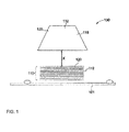
- FIG. 1 is a diagrammatical illustration of an exemplary embodiment of the ultraviolet (UV) cure manufacturing and repair system 130 in accordance with an embodiment disclosed herein.
- Composite structure 110 is shown as having a plurality of layers, or plies 112 of a UV curable composition reinforced with fiber or another material wherein the plurality of plies 112 are positioned on substrate 101. Plies 112 are positioned below UV radiation source 132 by distance X.
- Radiation source 132 may include a plurality of UV sources such as UV sources 118 and 132.
- composite structure 110 may include two or more layers, or plies, of another type of material.
- UV curable compositions employed herein advantageously can be cured by UV radiation without use of thermal energy from an external thermal source.
- the UV curable compositions include one or more photoinitiators that can generate free radicals when exposed to UV radiation of wavelength at which the photoinitiator is active.
- the UV curable compositions also contain one or more cure additives.
- Thick multilayer composites such as those that have a thickness of about 0.125 inches or more that employ the UV curable compositions may be cured without significant decay in the extent of cure through the layers of the composites.
- Multilayer composites that include the UV curable compositions can achieve uniform curing under UV radiation. Uniform curing may be achieved such as by creation of strong covalent bonds across interfaces of multiple layers and/or by creation of high glass transition temperatures across multiple layers of thick composites.
- Cure additives which may be employed in the UV curable composiotns include but are not limted to accelarators, adhesion promoters and mixtures threof.
- Accelarators that may be employed include but are not limited to cobalt promoters such as cobalt napthenate, cobalt octoate and mixtures thereof; aromatic amines such as dimethylaniline, diethylaniline and mixtures thereof, and mixtures of cobalt promoters and aromatic amines.
- Co promoters such as Co napthenate (6% solution) may be present in the UV curable composition in an amount of about 0.05% to about 5 %, preferably about 0.1 % to about 2 %, more preferably about 0.2 % to about 1 % where all amounts are based on the weight of the UV curable resin.
- an aromatic amine such as dimethylaniline may be present in the UV curable composition in an amount of about 0.01 % to about 5 %, preferably about 0.02% to about 2%, more preferably about 0.05% to about 1% where all amounts are based on the weight of the UV curable resin.
- the Co promoter (6% solution) may be present in the mixture in an amount of about 5% to about 95%, preferably about 15% to about 75%, more preferably about 40% to about 60% remainder aromatic amine, where all amounts are based on the total weight of the mixture of Co promoter and aromatic amine.
- the mixture may be present in a UV curable composition in an amount of about 0.06% to about 10%, preferably about 0.1 % to about 4%, more preferably about 0.2% to about 2% where all amounts are based on the weight of the UV curable resin.
- Cure additives in the form of accelerators may be present in the UV curable composition in an amount of about 0.05 % to about 10 %, preferably about 0.1 % to about 5%, more preferably about 0.2% to about 2 % by weight based on the weight of the UV curable resin component or UV curable monomer component of the UV curable composition.
- Cure additives in the form of adhesion promoters include but are not limited to alkyl phenoxy methacrylates such as phenoxyethyl methacrylate such as SR 340 from Sartomer Inc., butanediol dimethacrylates such as SR214 from Sartomer Inc., neopentyl glycol dimethacrylate such as SR248 from Sartomer Inc., ethoxylated bisphenol A dimethacrylate such as SR348 from Sartomer Inc., hexanediol dimethacrylate such as SR239 from Sartomer Inc., and mixtures thereof.
- alkyl phenoxy methacrylates such as phenoxyethyl methacrylate such as SR 340 from Sartomer Inc.
- butanediol dimethacrylates such as SR214 from Sartomer Inc.
- neopentyl glycol dimethacrylate such as SR248 from Sartomer
- acrylate and/or methacrylate monomers that may be employed as adhesion promoters include but are not limited to acrylate and/or methacrylate monomers such as those described in Olson, Pub US Application 20090229747 , the teachings of which are incorporated by reference herein by their entirety.
- photoinitiator as used herein is understood to mean a chemical compound that decomposes into free radicals when exposed to light but does not function as a thermal initiator.
- Photoinitiators that may be used in UV curable compositions such as those disclosed herein include but are not limited to quinones, benzophenones, nitroso compounds, acryl halides, hydrazones, mercapto compounds, pyrylium compounds, triacrylimidazoles, bisimidazoles, chloroalkyltriazines, benzoin ethers, benzil ketals, thioxanthones, acetophenones, acylphosphine oxides, derivatives of the aforementioned compounds, and mixtures thereof.
- Exemplary photoinitiators include benzil ketals such as 2,2-dimethoxy-2-phenyl acetophenone from Ciba Specialty Chemicals; acetophenone derivatives such as 2,2-diethoxyacetophenone ("DEAP” from First Chemical Corporation); 2-hydroxy-2-methyl-1-phenyl-propan-1-one ("HMPP” from Ciba Specialty Chemicals under the trademark DAROCURTM 1173); 2-benzyl-2-N, N-dimethylamino-1- (4-morpholinophenyl)-1-butanone from Ciba Specialty Chemicals; 2-methyl-1-(4-(methylthio)phenyl)-2-morpholinopropan-1-one from Ciba Specialty Chemicals; acylphosphine oxides such as 2,4,6-trimethylbenzoyl diphenylphosphine oxide (“TPO”), bis(2,6-dimethoxybenzoyl)-2,4,4-trimethylpentylphosphine oxide ("DM
- BTBPPO is available from Ciba Specialty Chemicals
- DMBAPO is available from Ciba Specialty Chemicals in the form of blends with other ketones including: 25/75 wt. % blend with HMPP and 1-hydroxy-cyclohexyl-phenyl-ketone, (or HCPK).
- TPO is also available from Ciba Specialty Chemicals in 50/50 wt. % blends with HMPP.
- the photoinitiators used are acylphosphine oxide type such as IRIGACURE ® 819 from Ciba Specialty Chemicals.
- Photoinitiators may be employed in an amount of about 0.01% to about 20%, preferably about 0.1% to about 10%, more preferably about 0.1% to about 5% by weight, based on the weight UV curable resin.
- the UV cure method according to various aspects of the present invention may be employed with UV curable resin compositions such as those that are free of thermal initiators.
- the UV cure method may be employed without use of an external thermal radiation source that might impart thermal heating to any of the layers before, during or after UV curing step or steps.
- photoinitiators in combination with at least one of the cure additives disclosed herein may enable uniform curing of the layers of a multi-layer composite structure throughout the thickness of the composite structure without use of thermal energy from an external thermal energy source.
- High glass transition temperatures in a plurality of layers of the composite structure may be achieved with strong secondary bonding and without significant decay in bonding strength among the layers.
- resin is understood to include a resin or a resin blend.
- the resin may include a reactive group.
- reactive group is understood to mean an atom or a group of atoms in an organic compound that provides the compound with characteristics which cause the compound to respond to a specific curing mechanism.
- reactive groups include aldehydes, amines, hydroxyl, acrylate, methacrylate, vinyl, cyclo-epoxide, glycidyl etherepoxide with amine curatives, urethane, thiol-ene reactive group or a combination thereof.
- resins that include one or more of these reactive groups are unsaturated polyesters, vinyl esters, melamines, urea-formaledehydes, phenolics, methacrylates, acrylates, epoxies, urethanes, etc.
- a plurality of layers 112 of a reinforced resin composite material are disposed in a stacked configuration and may be bonded by a covalent bond formed between adjacent layers 112 of composite material during curing to UV radiation without use of externally applied thermal energy to form composite structure 110.
- layers 112 include a reinforcing fiber or filler, such as, but not limited to high strength fibers such as E-glass and S-glass fibers.
- the reinforcing capability of the fibers, filler and combinations thereof may be increased by techniques known in the art, such as, but not limited to, forming a plurality of layers or plies, orientation of fibers in a selected direction, and like methods.
- the reinforcing fibers may be used in any conventional form such as braided, unidirectional, woven fabric, knitted fabric, swirl fabric, felt mat, wound, and the like.
- Exemplary fibers that may be used include but are not limited to glass fibers such as quartz, E-glass, S-2 glass, R-glass from suppliers such as PPG, AGY, St. Gobain, Owens-Corning, or Johns Manville.
- the fibers typically are at least partially UV transparent fibers such as but not limited to compositions of glass, quartz, silica, fumed silica, alumina, zirconia and the like. Nanoparticles of these compositions also may be employed as fillers, alone or in admixture with fibers. Mixtures of fibers also may be employed.
- Reinforcing fiber is typically present in the UV curable resin composition of a composite material in an amount of about 1% to about 85% by weight, more typically in an amount of about 10% to about 80% by weight, based on the weight of the UV curable composition. More preferably, reinforcing fiber may be present in an amount of about 45% to about 75% by weight based on the weight of the UV curable composition.
- a plurality of layers 112 of a composite material may include a plurality of fibers that form at least one composite fabric ply that includes a UV curable monomer or UV curable resin material.
- a UV curable monomer or resin may be applied to a fabric ply such as a glass fabric ply by pre-impregnating the UV curable monomer or resin into the fabric layer (e.g., pre-preg fabric). Inpregnating may be performed by infusing the UV curable monomer or resin into the fabric layer by vacuum-assisted resin transfer molding (VaRTM), resin transfer molding (RTM), or the like, or by brushing or rolling the UV curable monomer or resin onto the surface of the fabric layer until the resin material is absorbed.
- VaRTM vacuum-assisted resin transfer molding
- RTM resin transfer molding
- a plurality of layers 112 of a composite material include UV curable resins that have at least one reactive group, including but not limited to at least one ethylenic unit, cyclic ether unit, or epoxide unit, oxetane unit, or the like, or combinations thereof.
- the UV curable resins have at least one isocyanate unit, ester unit, or the like, or combinations thereof.
- Suitable UV curable resin materials include but are not limited to unsaturated polyesters such as POLYLITE® polyester resin available from Reichhold, SYNOLITE® polyester resin available from DSM, AROPOL® polyester resin available from Ashland; vinyl esters such as DION 9102-70, NORPOL® and HYDREX® resins available from Reichhold, DERAKANE®, DERAKANE MOMENTUM® and HETRON® resins available from Ashland, ATLAC E-NOVA® resin available from DSM and the like available from companies such as Cytec Surface Specialties, Sartomer, Rahn, and BASF.
- Other examples of resins that may be employed include but are not limited to those disclosed in Yang (US Pub. App. 2007/ 0066698 ) and Olson (US Pub. Appl. 2009/0229747 ) the teachings of each are incorporated by reference herein by their entireity.
- UV curable resins that may be employed include but are not limited to epoxy vinyl ester resins such as bisphenol-epoxy vinyl ester resins such as Dion 9102-70 from Reichhold, bisphenol-A epoxy vinyl ester resins, bisphenol-F epoxy vinyl ester resins, phenol novolac epoxy vinyl ester resins, cresol-novolac epoxy vinyl ester resins, biphenyl epoxy vinyl ester resins, multi-functional epoxy vinyl ester resins (i.e. epoxy resins that have two or more epoxy groups), and naphthalene epoxy vinyl ester resins (e.g., EPICLON® EXA-4700 from Dainippon Ink and Chemicals).
- epoxy vinyl ester resins such as bisphenol-epoxy vinyl ester resins such as Dion 9102-70 from Reichhold
- bisphenol-A epoxy vinyl ester resins bisphenol-F epoxy vinyl ester resins
- phenol novolac epoxy vinyl ester resins phenol novolac epoxy vinyl ester resins
- curable epoxy vinyl ester resins examples include but are not limited to those disclosed in Yang (US Pub. App. 2007/ 0066698 ) and Olson (US Pub. Appl. 2009/0229747 ) the teachings of each are incorporated by reference herein by their entireity.
- the photoinitiator in the UV curable composition may dissociate to generate free radicals or acid to initiate curing of the UV curable monomer or resin without use of thermal energy from an external thermal source.
- the time of exposure to UV radiation and the intensity of the UV radiation may vary. In various embodiments, the time of exposure to UV radiation and/or the intensity of UV radiation is sufficient to initiate photocuring without use of a thermal imitator. In particular embodiments the time of exposure to UV radiation is about 1 second to about 5 hours, preferably about 5 seconds to about 1 hour at an intensity of about 0.01 W/cm 2 to about 0.1 W/cm 2 , preferably about 0.03 W/cm 2 to about 0.06 W/cm 2 . In some embodiments, exposure to UV radiation is at an intensity of about 0.043W/cm 2 for about 30 min.
- the UV curable monomer or resin composition is exposed to UV radiation at an intensity and for a time sufficient to achieve complete curing, i.e., 90% or more curing of the monomer or resin.
- the UV radiation source may be turned off before complete curing of the resin is achieved.
- an additional thermal energy source need not be employed to cure the composition after UV radiation exposure is discontinued. The invention thereby enables use of an UV radiation source to achieve complete curing throughout the thickness of a composite layer, or layers without need for use of an additional thermal source to impart thermal heating, and significant reduction in energy usage and curing time.
- a suitable UV radiation source for UV curing is capable of emitting UV radiation having a wavelength of about 100 to about 400 nanometers.
- Suitable sources include ultraviolet fluorescent lamps, metal halide UV lamps, ultraviolet light emitting diodes, ultraviolet light emitting lasers, mercury arcs, carbon arcs, low pressure mercury arcs, medium pressure mercury arcs, medium pressure mercury lamps, high pressure mercury lamps, swirling flow plasma arcs, mercury and metal halide arcs, ultraviolet light emitting diodes, ultraviolet light emitting lasers, and the like.
- the UV curing method disclosed herein may be used in a stage wise curing process to build up a cured thickness of cured composite as needed.
- a first 5-ply thickness of composite laminate may be cured using the UV curing process disclosed herein.
- a second 5-ply thickness of composite laminate is cured on top of the first cured 5-ply laminate to achieve a cured 10-ply cured composite.
- Stage wise curing process may be employed to achieve cured thicknesses of about 1 ⁇ 4 in or more.
- the UV cure manufacturing and repair system is generally referenced as 130.
- a stack 110 formed of about 5-10 of layers 112 of a UV curable composite material is positioned on substrate 101.
- One or more of the plurality of layers 112 of UV curable composite material include a fiber reinforced UV curable epoxy vinyl ester resin composite material.
- the plurality of layers 112 of a composite material each include glass fiber reinforced epoxy vinyl ester UV curable resin photoinitiator composition that may be cured without a thermal initiator.
- UV radiation source 132 is provided and positioned a distance "X" from uppermost layer 120 of stack 110 to achieve a desired intensity of UV exposure, typically about 0.03 W/cm 2 to about 0.06 W/cm 2 .
- UV radiation source 132 may include a first UV radiation source 118 and a second UV radiation source 122 to initiate photocuring of the reactive group contained within the UV curable resin present in the plurality of layers of composite material 112.
- Radiation sources 118 and 122 may emit UV radiation at the same or different UV wavelengths. In the embodiment illustrated in FIG. 1 , UV radiation sources 118 and 122 are each capable of emitting UV radiation at a wavelength of about 100 nanometers to about 400 nanometers.
- UV radiation sources 118 and 122 may include mercury and metal halide arc lamps, ultraviolet fluorescent lamps, ultraviolet light emitting diodes, ultraviolet light emitting lasers, and the like.
- FIG. 6 illustrates a method 150 of curing a composite structure stack 110 in accordance with certain embodiments of the invention.
- Method 150 includes providing a composite material that includes a first layer of UV curable resin epoxy vinyl ester resin having a reactive group and a photoinitiator composition as in step 152.
- Method 150 includes providing one or more successive layers of a fiber reinforced resin having a reactive group as in step 154 until a desired number of layers in composite structure stack 110 are provided.
- Method 150 further include use of UV radiation to activate a UV curable epoxy vinyl ester monmer or a reactive group of a UV curable epoxy vinyl ester resin in one or more layers 112 of composite material in response to UV radiation source at step 158 to enable cure of one or more layers 112 of composite material.
- radiation sources 118 and 122 may be activated sequentially or simultaneously. As a non-limiting illustration, where activation of the UV radiation sources is sequential, first radtion source 118 may be activated followed by activation of radtion source 122. Following activation of second radiation source 122 , first radiation source 118 may be turned off.
- Stage wise curing may be used to achieve a desired thickness, typically about 0.25 in or more, of a composite structure.
- the UV cure process described above is repeated wherein a first set of layers of a composite material 112 is initially cured such as in accordance with method 150 and then an additional set of layers 112 of composite material is cured on top of the first set to achieve a desired thickness of composite structure.
- Example 1 DION 9102-70 vinyl ester resin is mixed with 0.2% Co napthenate, and 0.6% IRIGACURE 819 where the amounts of Co napthenate and IRIGACURE 819 are based on the weight of DION 9102-70 to form a UV curable resin composition.
- the composition was placed in a metal can and sealed with a lid. The sealed container was then placed on a roll jar mill for mixing for one-hour prior to use. Then, five 0.025 inch thick plies of dry glass fabric were stacked to a thickness of 0.125 inch. The stack of fabric is infused with the UV curable resin using the VARTM process at room temperature at 14 psi for 5 min to form an infused layer.
- a nylon flow media and a Teflon peel ply were applied to the infused layers.
- Polyethylene tubes and spiral wraps were used as resin inlet and vacuum outlet, respectively during infusion.
- a vacuum level of 30 in-Hg was used with nylon bagging and tacky tape during infusion.
- the infused fabric was cured with a UV-A lamp, 1000 KW from Sunrez Corp at an intensity of 0.04W/cm 2 for 30 minutes to produce a UV cured epoxy resin reinforced glass fiber panel.
- the composite panels had negligible void content ( ⁇ 0.5%).
- five additional layers of dry glass fabrics of 0.025-inch thickness each were placed on top of the UV cured epoxy/glass panel. These additional layers were infused with the UV curable resin using the VARTM process and cured with UV-A lamp as above.
- Example 2 The process of example 1 is repeated except that the mixture includes DION 9102-70 vinyl ester resin, 15%SR340, 0.2% Co napthenate, and 0.6 % IRIGACURE 819 where the amounts of SR340, Co napthenate, and IRIGACURE 819 are based on the weight of DION 9102-70.
- Table 1 Layer No. From Top to Bottom Dion 9102-70 & 0.6% Irgacure 819 & 15% SR340 Dion 9102-70 & 0.6% 819 & 0.2% Co napthenate Dion 9102-70 & 0.6% 819 & 0.2% Co napthenate & 15% SR 340 Dion 9102-70 & 0.6% Irgacure 819 1 Tg 1 92°C Tg 112°C Tg 94°C Tg 87°C (combined 1, 2, 3 layers) 3 Tg 81°C Tg 115°C Tg 93°C Tg 87°C 5 Tg 104°C Tg 117°C Tg 102°C Tg 85°C 7 Tg 105°C Tg 117°C Tg 102°C Tg 74°C 9 Tg 105°C Tg 101°C Tg 101°C Tg 101°C Tg 101°C Tg 101°C Tg 101°C Tg 101°C Tg 101
- the UV curable manufacture and repair system and method disclosed herein may provide desirable strength and potential for adhesive bonds in composite structures that employ epoxy vinyl ester monomers and resins such as those described herein. Joining and assembling of piece-parts and subcomponents into monolithic structures with the UV curable resin formulation and system is particularly advantageous and useful for modular fabrication. Although both mechanical and adhesively bonded joints may be used, adhesive bonds generally provide for lower weight products together with a desirable strength.
- Composite structures that include epoxy vinyl ester monomers and resins may be used as materials in mechanical components that may be adhesively bonded during joining and assembling of mechanical components.
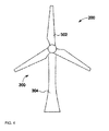
- FIG. 4 is a diagrammatical illustration of an exemplary embodiment of a composite structure 200 illustrating a wind turbine system 300 that includes at least a portion manufactured or repaired in accordance with embodiments disclosed herein.
- Some of the characteristics that make composites produced from UV curable compositions such as those disclosed herfein that include reinforcing fibers, fillers or combinations thereof suitable for high stress applications such as wind turbine blades include mechanical properties, tailorability of material properties, and versatility of fabrication methods.
- the composites also provide desirable toughness and shorter process cycle time than existing manufacturing processes where thermal energy curing is employed.
- the wind turbine system 300 shown in FIG. 4 includes a plurality of blades 302 (e.g., three blades) that enable system 300 to capture wind energy. Wind forces blades 302 to rotate about an axis to drive an electrical generator (not shown) disposed within system 300. Long blades are desirable since a long blade enables capture of higher amounts of wind energy.
- blades 302 have a typical length of about 30 meters to capture wind energy. Components of blade 302 may include the composite structure 110 as discussed below. Blades 302 are coupled to tower 304. The height of tower 304 determines the height of wind turbine system 300. Tower 304 is typically about two to three times the length of blades 302.
- FIG. 5 illustrates a modular design of blade 302 referenced in FIG. 4 of a wind turbine system 300 in which at least a portion of blade 302 is manufactured or repaired in accordance with certain embodiments of the invention.
- Blade 302 includes a top skin 306 and a shear web 308 disposed between a pair of spar caps 310 that are coupled to barrel 312. Shear web 308 provides strength to blade 302 and also provides support to the pair of spar caps 310.
- Blade 302 further includes a bottom skin 314 disposed below shear web 308. Any one or more of parts shown in Fig. 5 may be manufactured or repaired according to the embodiments disclosed herein. Since blade 302 is a significant component of the wind turbine blade system 300, using a composite structure, such as composite structure 110 such as shown in FIG. 1 , provides mechanical strength to turbine blade system 300, as well as a means of efficient and cost-effective repair and manufacture.
- the UV curing system and method disclosed herein are suitable for manufacture and repair of composite parts such as wind blade manufacture and repair.
- the UV curing method disclosed herein provides for efficient, cost effective in-field repair, including up-tower repair of thick multilayer laminates without use of thermal initiators and/or heating steps that require additional thermal radiation sources.
- the disclosed system and method of using UV radiation is suitable for curing glass fiber reinforced epoxy vinyl esters or epoxy vinyl ester laminates that include the UV cure composition disclosed herein.
- the UV radiation source can be configured as discrete stand-alone UV lamp or a plurality ofUV lamps.
- the UV curing method may be used as a stage wise curing process to build up thickness as needed.
Landscapes
- Chemical & Material Sciences (AREA)
- Engineering & Computer Science (AREA)
- Materials Engineering (AREA)
- Health & Medical Sciences (AREA)
- Organic Chemistry (AREA)
- Chemical Kinetics & Catalysis (AREA)
- Medicinal Chemistry (AREA)
- Polymers & Plastics (AREA)
- Physics & Mathematics (AREA)
- Mechanical Engineering (AREA)
- Manufacturing & Machinery (AREA)
- Electromagnetism (AREA)
- Toxicology (AREA)
- Oral & Maxillofacial Surgery (AREA)
- Thermal Sciences (AREA)
- Inorganic Chemistry (AREA)
- Life Sciences & Earth Sciences (AREA)
- Wood Science & Technology (AREA)
- Reinforced Plastic Materials (AREA)
- Laminated Bodies (AREA)
- Moulding By Coating Moulds (AREA)
Abstract
Description
- Curing methods for composite materials are disclosed, particularly, ultraviolet (UV) curing methods for use in manufacture and/or repair of structural composite products such as wind turbine rotor blade laminates.
- Wind turbines have received increased attention as environmentally safe and relatively inexpensive alternative energy sources. With this growing interest, considerable efforts have been made to develop manufacture and repair techniques for wind turbines that are reliable, efficient, and cost effective.
- A wind turbine includes a rotor that has multiple blades. The rotor is mounted to a housing or nacelle that is positioned on top of a truss or tubular tower. Utility grade wind turbines (i.e., wind turbines designed to provide electrical power to a utility grid) can have large rotors of 30 or more meters in length and generally have an average wind turbine rotor blade length of 24 meters to 47 meters. In addition, the wind turbines are typically mounted on towers that are at least 60 meters in height. Blades on these rotors transform wind energy into a rotational torque or force that drives one or more generators. Wind turbine rotor blade designs have become increasingly complex to maximize aerodynamic properties and to withstand a variety of environments and conditions.
- Generally, wind turbine rotor blades are fabricated from composite fiber materials and matrices composed of multiple layers or plies. In many instances, if certain material failures occur in the wind turbine rotor blade, the wind turbine is taken off-line and the wind turbine rotor blade replaced or repaired. The cost and time associated with transportation of replacement rotor blades and their installation is very high. Current methods used to repair wind turbine rotor blades are time and labor intensive and require special repair methods and facilities. Consequently, fabrication and repair of wind turbine rotor blades is difficult and expensive.
- A conventional approach utilized in both manufacture and repair of wind turbine blades involves curing multiple layers together at the same time in an autoclave or oven. The process entails applying the layers upon each other, and then curing all of the layers at the same time. Although adhesion between layers is generally good, other disadvantages can make this approach impractical. For instance, in manufacture or repair of the root section of a wind turbine blade, sagging and dimensional distortion and fiber wrinkling during compaction may occur during the curing cycle. Also, excessive reaction exotherm from thick parts may cause problems during curing.
- Another approach for curing of these multiple layers involves sequentially applying and completely curing layers one after another using a single curing mechanism. In other words, a first composite layer is cured completely before laying down a second composite layer. The second composite layer is then cured completely before laying down a third composite layer. The process adds additional composite layers in the same sequential manner using the single curing mechanism. Unfortunately, this fabrication technique creates relatively weak secondary adhesive bonds between the composite layers. These secondary adhesive bonds result in undesirably low interlaminar strength.
- In alternate situations, in-field repair including up-tower repair is feasible. In these situations, a thermal blanket heating process may be utilized. This process requires a green cure and an extended long thermal curing process to achieve desired physical and mechanical properties. The up-tower time required for the long thermal curing process contributes significant man-hour cost to wind blade repair processes.
- UV curing may provide faster laminate curing as an efficient in-field repair process. However, UV curing processes alone have been limited to thin laminate curing or require use of additional initiators and/or heating steps such as by use of external thermal radiation sources.
- A need therefore exists for an improved technique to provide fast, cost effective UV curing of thick multilayer composites without significant decay in the extent of cure of the inner layers of the composites. A further need exists for excellent glass transition temperatures in layers of thick multilayer composites without use of thermal initiators and/or use of additional thermal heating by external thermal sources. According to the present invention a system and method for manufacture and repair of multilayer composites is disclosed. The system includes a composite structure that employs a layer of a UV curable composition that includes a UV curable vinyl ester resin, a metal carboxylate accelerator, an adhesion promoter, and a trialkyl substituted benzoyl substituted aromatic phosphine oxide photoinitiator. The method entails forming a stack of a plurality of layers of fiber and/or filler reinforced UV curable resin composition. An UV radiation source is employed to cure the stack of layers through a thickness of the plurality of layers without use of thermal energy from an external source.
- The UV curable composition employed includes a photoinitiator and one more cure additives. The cure additives include a metal carboxylate accelator, an adhesion promotor such as one or more acylate monomers, methacylate monomers or mixtues thereof, and a trialkyl substituted benzoyl substituted aromatic phosphine oxide UV photoinitiator that enables curing of multiple layers without the use of thermal initiator and/or heating by additional external thermal sources such as thermal blankets or ovens.
- The disclosed UV cure system and method enables cure of layers in thick multilayer composites without significant decay in the extent of cure throughout the multiple layers of the composites. The disclosed UV cure system and method enables rapid, cost effective curing and improved curing throughout the layers in thick multilayer composites as may be required for wind blade repair, especially for up-tower repair.
- Various aspects and embodiments of the present invention will now be described in connection with the accompanying drawings, in which:
-
FIG. 1 illustrates a UV cure manufacturing and repair system in accordance with an embodiment disclosed herein; -
FIG 2 illustrates effects of cure additives on glass transition temperatures; -
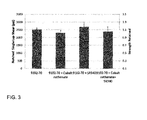
FIG 3 illustrates effects of cure additives on shear strength; -
FIG. 4 illustrates an exemplary embodiment of a composite structure used in a wind turbine system having blades manufactured or repaired with a UV curable composition in accordance with certain embodiments disclosed herein; -
FIG. 5 illustrates blades manufactured or repaired for use in a the wind turbine system such as that shown inFIG. 4 -
FIG. 6 illustrates a method of curing a composite structure in accordance with certain embodiments of the present invention. - UV curable compositions are disclosed that may be cured without a thermal initiator and/or without thermal heating step(s). Despite absence of a thermal initiator and/or additional thermal heating steps, complete curing of composite materials, that is 90% or more curing, can be attained.
- The UV curable compositions may be employed to enable rapid and thorough curing of composite structures to reduce manufacturing or repair cycle time, reduce plant and equipment investment, and decrease cost in manufacture and repair of a composite part. The UV curable compositions may be employed in a system and method disclosed herein for manufacture or repair of composite structures such as fiber reinforced resin structures.
- Embodiments presented herein provide an UV cure manufacture and repair system for composite structures and a method of manufacture and repair of a composite structure that employs a UV cure system.
- A composite structure as used herein is understood to mean a structure that has one or more composite layers, or plies. A composite structure may be manufactured and/or repaired using a UV curable resin composition. The UV curable resin composition may be employed to bond multiple composite layers. A composite layer includes one or more of filler, fiber or mixture thereof, a UV curable monomer or a UV curable reinforced resin that has a reactive group, and an UV curable composition described hereafter.
- In the specification and the claims that follow, singular forms "a", "an" and "the" include plural referents unless the context clearly dictates otherwise.
- The UV curable composition and UV curing mode used in the UV cure system and method of manufacture and repair may achieve uniform curing through multiple layers, may create covalent bonds across interfaces of the multiple layers, and may achieve high glass transition temperatures across the multiple layers without use of thermal energy such as that from an external thermal energy source.
-
FIG. 1 is a diagrammatical illustration of an exemplary embodiment of the ultraviolet (UV) cure manufacturing andrepair system 130 in accordance with an embodiment disclosed herein.Composite structure 110 is shown as having a plurality of layers, orplies 112 of a UV curable composition reinforced with fiber or another material wherein the plurality ofplies 112 are positioned onsubstrate 101.Plies 112 are positioned belowUV radiation source 132 by distance X.Radiation source 132 may include a plurality of UV sources such asUV sources composite structure 110 may include two or more layers, or plies, of another type of material. - UV curable compositions employed herein advantageously can be cured by UV radiation without use of thermal energy from an external thermal source. The UV curable compositions include one or more photoinitiators that can generate free radicals when exposed to UV radiation of wavelength at which the photoinitiator is active. The UV curable compositions also contain one or more cure additives. Thick multilayer composites such as those that have a thickness of about 0.125 inches or more that employ the UV curable compositions may be cured without significant decay in the extent of cure through the layers of the composites. Multilayer composites that include the UV curable compositions can achieve uniform curing under UV radiation. Uniform curing may be achieved such as by creation of strong covalent bonds across interfaces of multiple layers and/or by creation of high glass transition temperatures across multiple layers of thick composites.
- Cure additives which may be employed in the UV curable composiotns include but are not limted to accelarators, adhesion promoters and mixtures threof. Accelarators that may be employed include but are not limited to cobalt promoters such as cobalt napthenate, cobalt octoate and mixtures thereof; aromatic amines such as dimethylaniline, diethylaniline and mixtures thereof, and mixtures of cobalt promoters and aromatic amines.
- Where Co promoters are employed as accelerators, Co promoters such as Co napthenate (6% solution) may be present in the UV curable composition in an amount of about 0.05% to about 5 %, preferably about 0.1 % to about 2 %, more preferably about 0.2 % to about 1 % where all amounts are based on the weight of the UV curable resin.
- Where aromatic amines are employed as accelerators, an aromatic amine such as dimethylaniline may be present in the UV curable composition in an amount of about 0.01 % to about 5 %, preferably about 0.02% to about 2%, more preferably about 0.05% to about 1% where all amounts are based on the weight of the UV curable resin.
- Where mixtures of accelerators such as one or more Co promoters such as one or more of cobalt napthenate and cobalt octoate are employed together with one or more aromatic amines such as dimethylaniline and diethylaniline as accelerators, the Co promoter (6% solution) may be present in the mixture in an amount of about 5% to about 95%, preferably about 15% to about 75%, more preferably about 40% to about 60% remainder aromatic amine, where all amounts are based on the total weight of the mixture of Co promoter and aromatic amine.
- Where mixtures of Co promoter and aromatic amine are employed as accelerators, the mixture may be present in a UV curable composition in an amount of about 0.06% to about 10%, preferably about 0.1 % to about 4%, more preferably about 0.2% to about 2% where all amounts are based on the weight of the UV curable resin.
- Cure additives in the form of accelerators may be present in the UV curable composition in an amount of about 0.05 % to about 10 %, preferably about 0.1 % to about 5%, more preferably about 0.2% to about 2 % by weight based on the weight of the UV curable resin component or UV curable monomer component of the UV curable composition.
- Cure additives in the form of adhesion promoters that may be employed in the UV curable composition include but are not limited to alkyl phenoxy methacrylates such as phenoxyethyl methacrylate such as SR 340 from Sartomer Inc., butanediol dimethacrylates such as SR214 from Sartomer Inc., neopentyl glycol dimethacrylate such as SR248 from Sartomer Inc., ethoxylated bisphenol A dimethacrylate such as SR348 from Sartomer Inc., hexanediol dimethacrylate such as SR239 from Sartomer Inc., and mixtures thereof. Other acrylate and/or methacrylate monomers that may be employed as adhesion promoters include but are not limited to acrylate and/or methacrylate monomers such as those described in Olson, Pub
US Application 20090229747 , the teachings of which are incorporated by reference herein by their entirety. - The term "photoinitiator" as used herein is understood to mean a chemical compound that decomposes into free radicals when exposed to light but does not function as a thermal initiator.
- Photoinitiators that may be used in UV curable compositions such as those disclosed herein include but are not limited to quinones, benzophenones, nitroso compounds, acryl halides, hydrazones, mercapto compounds, pyrylium compounds, triacrylimidazoles, bisimidazoles, chloroalkyltriazines, benzoin ethers, benzil ketals, thioxanthones, acetophenones, acylphosphine oxides, derivatives of the aforementioned compounds, and mixtures thereof. Exemplary photoinitiators include benzil ketals such as 2,2-dimethoxy-2-phenyl acetophenone from Ciba Specialty Chemicals; acetophenone derivatives such as 2,2-diethoxyacetophenone ("DEAP" from First Chemical Corporation); 2-hydroxy-2-methyl-1-phenyl-propan-1-one ("HMPP" from Ciba Specialty Chemicals under the trademark DAROCUR™ 1173); 2-benzyl-2-N, N-dimethylamino-1- (4-morpholinophenyl)-1-butanone from Ciba Specialty Chemicals; 2-methyl-1-(4-(methylthio)phenyl)-2-morpholinopropan-1-one from Ciba Specialty Chemicals; acylphosphine oxides such as 2,4,6-trimethylbenzoyl diphenylphosphine oxide ("TPO"), bis(2,6-dimethoxybenzoyl)-2,4,4-trimethylpentylphosphine oxide ("DMBAPO"), or bis(2,4,6-trimethylbenzoyl)-phenylphosphine oxide ("BTBPPO"). BTBPPO is available from Ciba Specialty Chemicals; DMBAPO is available from Ciba Specialty Chemicals in the form of blends with other ketones including: 25/75 wt. % blend with HMPP and 1-hydroxy-cyclohexyl-phenyl-ketone, (or HCPK). TPO is also available from Ciba Specialty Chemicals in 50/50 wt. % blends with HMPP. In a preferred embodiment the photoinitiators used are acylphosphine oxide type such as IRIGACURE ® 819 from Ciba Specialty Chemicals.
- Photoinitiators may be employed in an amount of about 0.01% to about 20%, preferably about 0.1% to about 10%, more preferably about 0.1% to about 5% by weight, based on the weight UV curable resin.
- The UV cure method according to various aspects of the present invention may be employed with UV curable resin compositions such as those that are free of thermal initiators. The UV cure method may be employed without use of an external thermal radiation source that might impart thermal heating to any of the layers before, during or after UV curing step or steps.
- It has been discovered that the use of photoinitiators in combination with at least one of the cure additives disclosed herein may enable uniform curing of the layers of a multi-layer composite structure throughout the thickness of the composite structure without use of thermal energy from an external thermal energy source. High glass transition temperatures in a plurality of layers of the composite structure may be achieved with strong secondary bonding and without significant decay in bonding strength among the layers.
- As used herein, "resin" is understood to include a resin or a resin blend. The resin may include a reactive group.
- As used herein, the term "reactive group" is understood to mean an atom or a group of atoms in an organic compound that provides the compound with characteristics which cause the compound to respond to a specific curing mechanism. Non-limiting examples of reactive groups include aldehydes, amines, hydroxyl, acrylate, methacrylate, vinyl, cyclo-epoxide, glycidyl etherepoxide with amine curatives, urethane, thiol-ene reactive group or a combination thereof. Some non-limiting examples of resins that include one or more of these reactive groups are unsaturated polyesters, vinyl esters, melamines, urea-formaledehydes, phenolics, methacrylates, acrylates, epoxies, urethanes, etc.
- In
FIG. 1 , a plurality oflayers 112 of a reinforced resin composite material are disposed in a stacked configuration and may be bonded by a covalent bond formed betweenadjacent layers 112 of composite material during curing to UV radiation without use of externally applied thermal energy to formcomposite structure 110. In particular embodiments,layers 112 include a reinforcing fiber or filler, such as, but not limited to high strength fibers such as E-glass and S-glass fibers. The reinforcing capability of the fibers, filler and combinations thereof may be increased by techniques known in the art, such as, but not limited to, forming a plurality of layers or plies, orientation of fibers in a selected direction, and like methods. The reinforcing fibers may be used in any conventional form such as braided, unidirectional, woven fabric, knitted fabric, swirl fabric, felt mat, wound, and the like. Exemplary fibers that may be used include but are not limited to glass fibers such as quartz, E-glass, S-2 glass, R-glass from suppliers such as PPG, AGY, St. Gobain, Owens-Corning, or Johns Manville. The fibers typically are at least partially UV transparent fibers such as but not limited to compositions of glass, quartz, silica, fumed silica, alumina, zirconia and the like. Nanoparticles of these compositions also may be employed as fillers, alone or in admixture with fibers. Mixtures of fibers also may be employed. Reinforcing fiber is typically present in the UV curable resin composition of a composite material in an amount of about 1% to about 85% by weight, more typically in an amount of about 10% to about 80% by weight, based on the weight of the UV curable composition. More preferably, reinforcing fiber may be present in an amount of about 45% to about 75% by weight based on the weight of the UV curable composition. - In a non-limiting example, a plurality of
layers 112 of a composite material may include a plurality of fibers that form at least one composite fabric ply that includes a UV curable monomer or UV curable resin material. A UV curable monomer or resin may be applied to a fabric ply such as a glass fabric ply by pre-impregnating the UV curable monomer or resin into the fabric layer (e.g., pre-preg fabric). Inpregnating may be performed by infusing the UV curable monomer or resin into the fabric layer by vacuum-assisted resin transfer molding (VaRTM), resin transfer molding (RTM), or the like, or by brushing or rolling the UV curable monomer or resin onto the surface of the fabric layer until the resin material is absorbed. - In some embodiments, a plurality of
layers 112 of a composite material include UV curable resins that have at least one reactive group, including but not limited to at least one ethylenic unit, cyclic ether unit, or epoxide unit, oxetane unit, or the like, or combinations thereof. In other embodiments, the UV curable resins have at least one isocyanate unit, ester unit, or the like, or combinations thereof. Suitable UV curable resin materials include but are not limited to unsaturated polyesters such as POLYLITE® polyester resin available from Reichhold, SYNOLITE® polyester resin available from DSM, AROPOL® polyester resin available from Ashland; vinyl esters such as DION 9102-70, NORPOL® and HYDREX® resins available from Reichhold, DERAKANE®, DERAKANE MOMENTUM® and HETRON® resins available from Ashland, ATLAC E-NOVA® resin available from DSM and the like available from companies such as Cytec Surface Specialties, Sartomer, Rahn, and BASF. Other examples of resins that may be employed include but are not limited to those disclosed inYang (US Pub. App. 2007/ 0066698 ) andOlson (US Pub. Appl. 2009/0229747 ) the teachings of each are incorporated by reference herein by their entireity. - In some embodiments, UV curable resins that may be employed include but are not limited to epoxy vinyl ester resins such as bisphenol-epoxy vinyl ester resins such as Dion 9102-70 from Reichhold, bisphenol-A epoxy vinyl ester resins, bisphenol-F epoxy vinyl ester resins, phenol novolac epoxy vinyl ester resins, cresol-novolac epoxy vinyl ester resins, biphenyl epoxy vinyl ester resins, multi-functional epoxy vinyl ester resins (i.e. epoxy resins that have two or more epoxy groups), and naphthalene epoxy vinyl ester resins (e.g., EPICLON® EXA-4700 from Dainippon Ink and Chemicals).
- Examples of other curable epoxy vinyl ester resins that may be employed include but are not limited to those disclosed in
Yang (US Pub. App. 2007/ 0066698 ) andOlson (US Pub. Appl. 2009/0229747 ) the teachings of each are incorporated by reference herein by their entireity. - Upon exposure to a UV radiation source, the photoinitiator in the UV curable composition may dissociate to generate free radicals or acid to initiate curing of the UV curable monomer or resin without use of thermal energy from an external thermal source. The time of exposure to UV radiation and the intensity of the UV radiation may vary. In various embodiments, the time of exposure to UV radiation and/or the intensity of UV radiation is sufficient to initiate photocuring without use of a thermal imitator. In particular embodiments the time of exposure to UV radiation is about 1 second to about 5 hours, preferably about 5 seconds to about 1 hour at an intensity of about 0.01 W/cm2 to about 0.1 W/cm2, preferably about 0.03 W/cm2 to about 0.06 W/cm2. In some embodiments, exposure to UV radiation is at an intensity of about 0.043W/cm2 for about 30 min.
- In some embodiments the UV curable monomer or resin composition is exposed to UV radiation at an intensity and for a time sufficient to achieve complete curing, i.e., 90% or more curing of the monomer or resin. The UV radiation source may be turned off before complete curing of the resin is achieved. Advantageously, an additional thermal energy source need not be employed to cure the composition after UV radiation exposure is discontinued. The invention thereby enables use of an UV radiation source to achieve complete curing throughout the thickness of a composite layer, or layers without need for use of an additional thermal source to impart thermal heating, and significant reduction in energy usage and curing time.
- A suitable UV radiation source for UV curing is capable of emitting UV radiation having a wavelength of about 100 to about 400 nanometers. Suitable sources include ultraviolet fluorescent lamps, metal halide UV lamps, ultraviolet light emitting diodes, ultraviolet light emitting lasers, mercury arcs, carbon arcs, low pressure mercury arcs, medium pressure mercury arcs, medium pressure mercury lamps, high pressure mercury lamps, swirling flow plasma arcs, mercury and metal halide arcs, ultraviolet light emitting diodes, ultraviolet light emitting lasers, and the like.
- The UV curing method disclosed herein may be used in a stage wise curing process to build up a cured thickness of cured composite as needed. For example, a first 5-ply thickness of composite laminate may be cured using the UV curing process disclosed herein. Then, a second 5-ply thickness of composite laminate is cured on top of the first cured 5-ply laminate to achieve a cured 10-ply cured composite. Stage wise curing process may be employed to achieve cured thicknesses of about ¼ in or more.
- In
FIG. 1 , the UV cure manufacturing and repair system is generally referenced as 130. Like numerals refer to like elements throughout the several views. InFIG. 1 , astack 110 formed of about 5-10 oflayers 112 of a UV curable composite material is positioned onsubstrate 101. One or more of the plurality oflayers 112 of UV curable composite material include a fiber reinforced UV curable epoxy vinyl ester resin composite material. In a preferred aspect, the plurality oflayers 112 of a composite material each include glass fiber reinforced epoxy vinyl ester UV curable resin photoinitiator composition that may be cured without a thermal initiator. AnUV radiation source 132 is provided and positioned a distance "X" fromuppermost layer 120 ofstack 110 to achieve a desired intensity of UV exposure, typically about 0.03 W/cm2 to about 0.06 W/cm2.UV radiation source 132 may include a firstUV radiation source 118 and a secondUV radiation source 122 to initiate photocuring of the reactive group contained within the UV curable resin present in the plurality of layers ofcomposite material 112.Radiation sources FIG. 1 ,UV radiation sources UV radiation sources -
FIG. 6 illustrates amethod 150 of curing acomposite structure stack 110 in accordance with certain embodiments of the invention.Method 150 includes providing a composite material that includes a first layer of UV curable resin epoxy vinyl ester resin having a reactive group and a photoinitiator composition as instep 152.Method 150 includes providing one or more successive layers of a fiber reinforced resin having a reactive group as instep 154 until a desired number of layers incomposite structure stack 110 are provided.Method 150 further include use of UV radiation to activate a UV curable epoxy vinyl ester monmer or a reactive group of a UV curable epoxy vinyl ester resin in one ormore layers 112 of composite material in response to UV radiation source atstep 158 to enable cure of one ormore layers 112 of composite material. Inmethod 150,radiation sources first radtion source 118 may be activated followed by activation ofradtion source 122. Following activation ofsecond radiation source 122 ,first radiation source 118 may be turned off. - Stage wise curing may be used to achieve a desired thickness, typically about 0.25 in or more, of a composite structure. In stage wise curing, the UV cure process described above is repeated wherein a first set of layers of a
composite material 112 is initially cured such as in accordance withmethod 150 and then an additional set oflayers 112 of composite material is cured on top of the first set to achieve a desired thickness of composite structure. - Example 1: DION 9102-70 vinyl ester resin is mixed with 0.2% Co napthenate, and 0.6% IRIGACURE 819 where the amounts of Co napthenate and IRIGACURE 819 are based on the weight of DION 9102-70 to form a UV curable resin composition. The composition was placed in a metal can and sealed with a lid. The sealed container was then placed on a roll jar mill for mixing for one-hour prior to use. Then, five 0.025 inch thick plies of dry glass fabric were stacked to a thickness of 0.125 inch. The stack of fabric is infused with the UV curable resin using the VARTM process at room temperature at 14 psi for 5 min to form an infused layer. A nylon flow media and a Teflon peel ply were applied to the infused layers. Polyethylene tubes and spiral wraps were used as resin inlet and vacuum outlet, respectively during infusion. A vacuum level of 30 in-Hg was used with nylon bagging and tacky tape during infusion.
- The infused fabric was cured with a UV-A lamp, 1000 KW from Sunrez Corp at an intensity of 0.04W/cm2 for 30 minutes to produce a UV cured epoxy resin reinforced glass fiber panel. The composite panels had negligible void content (<0.5%). Then, five additional layers of dry glass fabrics of 0.025-inch thickness each were placed on top of the UV cured epoxy/glass panel. These additional layers were infused with the UV curable resin using the VARTM process and cured with UV-A lamp as above.
- Example 2: The process of example 1 is repeated except that the mixture includes DION 9102-70 vinyl ester resin, 15%SR340, 0.2% Co napthenate, and 0.6 % IRIGACURE 819 where the amounts of SR340, Co napthenate, and IRIGACURE 819 are based on the weight of DION 9102-70.
- The process of example 1 is used except that only DION 9102-70 vinyl ester resin was employed.
- The results of examples 1 and 2, and of comparative example 1, are shown in Tables 1 and 2, and in
FIGS. 2 and3 .Table 1 Layer No. From Top to Bottom Dion 9102-70 & 0.6% Irgacure 819 & 15% SR340 Dion 9102-70 & 0.6% 819 & 0.2% Co napthenate Dion 9102-70 & 0.6% 819 & 0.2% Co napthenate & 15% SR 340 Dion 9102-70 & 0.6% Irgacure 819 1 Tg 1 92° C Tg 112°C Tg 94°C Tg 87°C (combined 1, 2, 3 layers) 3 Tg 81°C Tg 115°C Tg 93°C Tg 87°C 5 Tg 104°C Tg 117°C Tg 102°C Tg 85°C 7 Tg 105°C Tg 117°C Tg 102°C Tg 74°C 9 Tg 105° C Tg 101° C Tg 101°C Tg 59° C 10 Not tested Tg 105°C Not tested Tg 55°C 1. The onset of storage modulus, G', is used to determine the Tg from a Dynamic Mechanical Analysis curve. Table 2 Samples Dion 9102-70 & 0.6% Irgacure 819 & 0.2% Co napthenate Dion 9102-70 & 0.6% Irgacure 819 & 15% SR340 Dion 9102-70 & 0.6% 819 & 0.2% Co napthenate + 15% SR 340 Dion 9102-70 & 0.6% Irgacure 819 Notched single lap shear (ksi) 1 2.4 +/- 0.3 2.7 +/- 0.2 2.3 +/- 0.2 2.5 +/- 0.1 1. Modified ASTM method D3165, a-c, 5-ply UV cured laminate on 5-ply thermal epoxy based substrate - As shown in Table 1 and in
FIGS 2 and3 , when the resin formulation contains vinyl ester resin (Dion 9102-70) alone, only a few top plies of the ten-ply stack reach a Tg above 80 °C. However, when the resin formulation is a UV curable resin formulation that contains vinyl ester resin (Dion 9102-70) in combination with Co napthenate and/or SR 340, each of the ten plies of the stack reach a Tg of 80°C to over 100 °C. Also, addition of cobalt napthenate and SR340 does not cause any significant reduction on the bonding strength with epoxy based composite substrate. - The UV curable manufacture and repair system and method disclosed herein may provide desirable strength and potential for adhesive bonds in composite structures that employ epoxy vinyl ester monomers and resins such as those described herein. Joining and assembling of piece-parts and subcomponents into monolithic structures with the UV curable resin formulation and system is particularly advantageous and useful for modular fabrication. Although both mechanical and adhesively bonded joints may be used, adhesive bonds generally provide for lower weight products together with a desirable strength. Composite structures that include epoxy vinyl ester monomers and resins may be used as materials in mechanical components that may be adhesively bonded during joining and assembling of mechanical components.
-
FIG. 4 is a diagrammatical illustration of an exemplary embodiment of acomposite structure 200 illustrating awind turbine system 300 that includes at least a portion manufactured or repaired in accordance with embodiments disclosed herein. Some of the characteristics that make composites produced from UV curable compositions such as those disclosed herfein that include reinforcing fibers, fillers or combinations thereof suitable for high stress applications such as wind turbine blades include mechanical properties, tailorability of material properties, and versatility of fabrication methods. The composites also provide desirable toughness and shorter process cycle time than existing manufacturing processes where thermal energy curing is employed. - The
wind turbine system 300 shown inFIG. 4 includes a plurality of blades 302 (e.g., three blades) that enablesystem 300 to capture wind energy.Wind forces blades 302 to rotate about an axis to drive an electrical generator (not shown) disposed withinsystem 300. Long blades are desirable since a long blade enables capture of higher amounts of wind energy. - In a non-limiting example of a
wind turbine system 300,blades 302 have a typical length of about 30 meters to capture wind energy. Components ofblade 302 may include thecomposite structure 110 as discussed below.Blades 302 are coupled to tower 304. The height oftower 304 determines the height ofwind turbine system 300.Tower 304 is typically about two to three times the length ofblades 302. -
FIG. 5 illustrates a modular design ofblade 302 referenced inFIG. 4 of awind turbine system 300 in which at least a portion ofblade 302 is manufactured or repaired in accordance with certain embodiments of the invention.Blade 302 includes atop skin 306 and ashear web 308 disposed between a pair of spar caps 310 that are coupled tobarrel 312.Shear web 308 provides strength toblade 302 and also provides support to the pair of spar caps 310.Blade 302 further includes abottom skin 314 disposed belowshear web 308. Any one or more of parts shown inFig. 5 may be manufactured or repaired according to the embodiments disclosed herein. Sinceblade 302 is a significant component of the windturbine blade system 300, using a composite structure, such ascomposite structure 110 such as shown inFIG. 1 , provides mechanical strength toturbine blade system 300, as well as a means of efficient and cost-effective repair and manufacture. - The UV curing system and method disclosed herein are suitable for manufacture and repair of composite parts such as wind blade manufacture and repair. The UV curing method disclosed herein provides for efficient, cost effective in-field repair, including up-tower repair of thick multilayer laminates without use of thermal initiators and/or heating steps that require additional thermal radiation sources.
- The disclosed system and method of using UV radiation is suitable for curing glass fiber reinforced epoxy vinyl esters or epoxy vinyl ester laminates that include the UV cure composition disclosed herein. The UV radiation source can be configured as discrete stand-alone UV lamp or a plurality ofUV lamps. In addition, the UV curing method may be used as a stage wise curing process to build up thickness as needed.
- A written description of the invention has been provided herein, however, the description is not intended to nor should be construed as placing limitations on modifications and changes that will occur to those skilled in the relevant art upon review of the description herein.
- Various aspects and embodiments of the present invention are defined by the following numbered clauses:
- 1. A method of manufacture of a UV cured resin composite comprising:
- providing a UV curable composition comprising bisphenol-epoxy vinyl ester resin, Co napthenate, and a photoinitiator;
- infusing one or more plies of glass fabric with the UV curable composition to produce an UV resin infused fabric; and
- treating the infused fabric with UV radiation for a time period of about 1 second to about 5 hours at an intensity of about 0.01 W/cm2 to about 0.1 W/cm2 in the absence of thermal energy from an external thermal source to form a UV cured resin composite.
- 2. The method of clause 1, wherein time period is about 5 seconds to about 1 hour and the intensity is about 0.043W/cm2.
- 3. The method of any preceding clause, wherein the photoinitiator is 2,2-dimethoxy-2-phenyl acetophenone.
- 4. The method of any preceding clause, wherein the mixture further comprises phenoxyethyl methacrylate.
- 5. A method of manufacture of a UV cured resin composite comprising:
- providing a UV curable composition comprising epoxy vinyl ester resin;
- an accelerator is selected from the group consisting of cobalt napthenate, cobalt octoate dimethylaniline, diethylaniline and mixtures thereof;
- a photoinitiator selected from the group consisting of quinones, benzophenones, nitroso compounds, acryl halides, hydrazones, mercapto compounds, pyrylium compounds, triacrylimidazoles, bisimidazoles, chloroalkyltriazines, benzoin ethers, benzil ketals, thioxanthones, acetophenones, acylphosphine oxides, derivatives of the aforementioned compounds, and mixtures thereof;
- infusing one or more plies of reinforcement wherein the reinforcement is any one or more of carbon fabric, glass fabric and filler with the UV curable composition to produce an UV resin infused preform; and
- treating the infused preform with UV radiation for a time period of about 1 second to about 5 hours at an intensity of about 0.01 W/cm2 to about 0.1 W/cm2 in the absence of thermal energy from an additional thermal source to form a UV cured resin composite.
- 6. The method of any preceding clause, wherein the composition further comprises an alkyl phenoxy methacrylate.
- 7. The method of any preceding clause, wherein the alkyl phenoxy methacrylate is selected from the group consisting of phenoxyethyl methacrylate, butanediol dimethacrylate, neopentyl glycol dimethacrylate, ethoxylated bisphenol A dimethacrylate, hexanediol dimethacrylate and mixtures thereof.
- 8. A method of manufacture of a UV cured resin composite comprising, providing a UV curable composition a vinyl ester resin, a metal carboxylate accelerator, an adhesion promoter, and a photoinitiator.
- 9. The method of any preceding clause, wherein the photoinitiator is trialkyl substituted benzoyl substituted aromatic phosphine oxide.
- 10. A UV curable composition capable of curing under UV radiation in the absence of thermal radiation from an additional thermal source wherein the UV curable compositon comprises a vinyl ester resin, accelerator, an adhesion promoter, and a photoinitiator.
- 11. The composition of any preceding clause, wherein the accelerator is selected from the group consisting of cobalt carboxylates, aromatic amines and mixtures threof.
- 12. The composition of any preceding clause, wherein the cobalt carboxylage is selectd from the group consisitng of cobalt napthenate, cobalt octoate and mixtures thereof and the aromatic amine is selected from the group consisting of dimethylaniline, diethylaniline and mixtures thereof.
- 13. The composition of any preceding clause, wherein the vinyl ester resin comprises a bisphenol-epoxy vinyl ester resin.
- 14. The composition of any preceding clause, wherein the vinyl ester resin comprises any one or more of a multifunctional epoxy vinyl ester resins and multi-aromatic epoxy resins.
- 15. The compositon of any preceding clause, wherein the vinyl ester resin futher comprises cycloaliphatic epoxide resins, bisphenol-A epoxy vinyl ester resins, bisphenol-F epoxy vinyl ester resins, phenol novolac epoxy vinyl ester resins, cresol-novolac epoxy vinyl ester resins, biphenyl epoxy vinyl ester resins, naphthalene epoxy vinyl ester resins, divinylbenzene dioxide, 2-glycidylphenylglycidyl ether and mixtures thereof.
- 16. A method manufacture of a multilayer UV cured resin composite comprising:
- a first step of providing a first set of one or more layers comprising a UV curable resin composition having reinforcement, a reactive group, photoinitiator and accelerator wherein the UV curable resin is curabable in the presence of UV radiation and in the absence of thermal energy from an additional thermal energy source;
- a second step of applying UV radiation to the first set to to cure the first set in the absence of thermal energy from an additional thermal source to form a cured first set of layers;
- a third step of providing additional layers of the reinforced UV curable esin over the cured first set;
- repeating the second and third steps to produce a multilayer UV cured resinforced resin compositge desired thickness.
- 17. The method of any preceding clause, wherein the UV radiation has a wavelength of about 100 nm to about 400 nm.
- 18. The method of any preceding clause, wherein the UV radiation is at an intensity of about 0.03 W/cm2 to about 0.06 W/cm2
- 19. The method of any preceding clause, wherein the applying of UV radiation is for a time of about 1 second to about 5 hours.
- 20. The method of any preceding clause, wherein the UV reinforcement is any one or more of fibers, fillers, and mixtures thereof wherein the filbers are selected from the group consisting of glass fibers, quartz fibers, alumina fibers, zirconia fibers and mixtures thereof, and the fillers are selected from the group consisitng of glass, quartz, silica, fumed silica, alumina, zirconia and mixtures thereof.
Claims (15)
- A method (150) of manufacture of a UV cured resin composite (112) comprising:providing a UV curable composition comprising bisphenol-epoxy vinyl ester resin, Co napthenate, and a photoinitiator;infusing one or more plies of glass fabric with the UV curable composition to produce an UV resin infused fabric; andtreating the infused fabric with UV radiation for a time period of about 1 second to about 5 hours at an intensity of about 0.01 W/cm2 to about 0.1 W/cm2 in the absence of thermal energy from an external thermal source to form a UV cured resin composite (112).
- The method (150) of claim 1, wherein time period is about 5 seconds to about 1 hour and the intensity is about 0.043 W/cm2.
- The method (150) of any preceding claim, wherein the photoinitiator is 2,2-dimethoxy-2-phenyl acetophenone.
- The method (150) of any preceding claim, wherein the mixture further comprises phenoxyethyl methacrylate.
- A method (150) of manufacture of a UV cured resin composite (112) comprising:providing a UV curable composition comprising epoxy vinyl ester resin;an accelerator is selected from the group consisting of cobalt napthenate, cobalt octoate dimethylaniline, diethylaniline and mixtures thereof;a photoinitiator selected from the group consisting of quinones, benzophenones, nitroso compounds, acryl halides, hydrazones, mercapto compounds, pyrylium compounds, triacrylimidazoles, bisimidazoles, chloroalkyltriazines, benzoin ethers, benzil ketals, thioxanthones, acetophenones, acylphosphine oxides, derivatives of the aforementioned compounds, and mixtures thereof;infusing one or more plies of reinforcement wherein the reinforcement is any one or more of carbon fabric, glass fabric and filler with the UV curable composition to produce an UV resin infused preform; andtreating the infused preform with UV radiation for a time period of about 1 second to about 5 hours at an intensity of about 0.01 W/cm2 to about 0.1 W/cm2 in the absence of thermal energy from an additional thermal source to form a UV cured resin composite.
- The method (150) of claim 5, wherein the composition further comprises an alkyl phenoxy methacrylate.
- The method (150) of claim 5 or claim 6, wherein the alkyl phenoxy methacrylate is selected from the group consisting of phenoxyethyl methacrylate, butanediol dimethacrylate, neopentyl glycol dimethacrylate, ethoxylated bisphenol A dimethacrylate, hexanediol dimethacrylate and mixtures thereof.
- A method (150) of manufacture of a UV cured resin composite comprising, providing a UV curable composition a vinyl ester resin, a metal carboxylate accelerator, an adhesion promoter, and a photoinitiator.
- The method (150) of claim 8, wherein the photoinitiator is trialkyl substituted benzoyl substituted aromatic phosphine oxide.
- A UV curable composition (112) capable of curing under UV radiation in the absence of thermal radiation from an additional thermal source wherein the UV curable compositon comprises a vinyl ester resin, accelerator, an adhesion promoter, and a photoinitiator.
- The composition (112) of claim 10, wherein the accelerator is selected from the group consisting of cobalt carboxylates, aromatic amines and mixtures threof.
- The composition (112) of claim 10 or claim 11, wherein the cobalt carboxylage is selected from the group consisitng of cobalt napthenate, cobalt octoate and mixtures thereof and the aromatic amine is selected from the group consisting of dimethylaniline, diethylaniline and mixtures thereof.
- The composition (112) of any of claims 10 to 12, wherein the vinyl ester resin comprises a bisphenol-epoxy vinyl ester resin.
- The composition (112) of claim 13, wherein the vinyl ester resin comprises any one or more of a multifunctional epoxy vinyl ester resins and multi-aromatic epoxy resins.
- The composition (112) of claim 13 or claim 14, wherein the vinyl ester resin futher compreises cycloaliphatic epoxide resins, bisphenol-A epoxy vinyl ester resins, bisphenol-F epoxy vinyl ester resins, phenol novolac epoxy vinyl ester resins, cresol-novolac epoxy vinyl ester resins, biphenyl epoxy vinyl ester resins, naphthalene epoxy vinyl ester resins, divinylbenzene dioxide, 2-glycidylphenylglycidyl ether and mixtures thereof.
Applications Claiming Priority (1)
| Application Number | Priority Date | Filing Date | Title |
|---|---|---|---|
| US13/619,154 US20140077420A1 (en) | 2012-09-14 | 2012-09-14 | UV Curing System and Method For Wind Blade Manufacture And Repair |
Publications (1)
| Publication Number | Publication Date |
|---|---|
| EP2708572A1 true EP2708572A1 (en) | 2014-03-19 |
Family
ID=49182091
Family Applications (1)
| Application Number | Title | Priority Date | Filing Date |
|---|---|---|---|
| EP20130183940 Withdrawn EP2708572A1 (en) | 2012-09-14 | 2013-09-11 | UV Curing System and Method for Wind Blade Manufacture and Repair |
Country Status (3)
| Country | Link |
|---|---|
| US (1) | US20140077420A1 (en) |
| EP (1) | EP2708572A1 (en) |
| CA (1) | CA2826441A1 (en) |
Cited By (1)
| Publication number | Priority date | Publication date | Assignee | Title |
|---|---|---|---|---|
| CN109504331A (en) * | 2018-10-30 | 2019-03-22 | 武汉市科达云石护理材料有限公司 | A kind of two-part room temperature curing adhesive and preparation method thereof |
Families Citing this family (11)
| Publication number | Priority date | Publication date | Assignee | Title |
|---|---|---|---|---|
| EP2266727B1 (en) * | 2009-06-22 | 2015-10-14 | The Gillette Company | A method of forming a functional razor cartridge |
| DE102012221942A1 (en) * | 2012-11-30 | 2014-06-05 | Wobben Properties Gmbh | Process for the machining of a fiber-plastic composite of a rotor blade, semifinished product in the form of a structural composite and UV lamp for curing a UV-curable matrix material |
| EP3484763B1 (en) | 2016-07-14 | 2023-11-29 | Helios Applied Science | Photoinitiation-based deployable structures |
| GB2583920B (en) * | 2019-05-10 | 2023-09-27 | Henkel Ag & Co Kgaa | Method for bonding three-dimensional articles made by additive manufacturing |
| US20230051188A1 (en) * | 2019-12-18 | 2023-02-16 | 3M Innovative Properties Company | Composition including unsaturated polyester resin, epoxy resin, and photoinitiator and method of using the same |
| CN113045865B (en) * | 2021-05-18 | 2021-11-30 | 哈尔滨工业大学 | Photocuring method of large-area dark fiber cloth epoxy composite material |
| CN113352657A (en) * | 2021-05-28 | 2021-09-07 | 哈尔滨理工大学 | Method and device for photocuring maintenance of pole tower composite material |
| CN113665148A (en) * | 2021-08-31 | 2021-11-19 | 重庆重通成飞新材料有限公司 | Method for repairing blade of wind driven generator through photocuring |
| PL4177045T3 (en) * | 2021-11-08 | 2024-08-05 | Siemens Gamesa Renewable Energy A/S | Method of repairing a wind turbine blade and respectively repaired wind turbine blade |
| US12275107B2 (en) | 2022-10-26 | 2025-04-15 | Saudi Arabian Oil Company | Systems and methods of defect repair of metal pipelines using composite wrap repair with diode laser curing |
| GB202408136D0 (en) | 2024-06-07 | 2024-07-24 | Scott Bader Co | UV-curable filler compositions |
Citations (7)
| Publication number | Priority date | Publication date | Assignee | Title |
|---|---|---|---|---|
| JP2005054107A (en) * | 2003-08-06 | 2005-03-03 | Showa Highpolymer Co Ltd | Heat-resistant adhesive and its using method |
| US20070066698A1 (en) | 2005-09-20 | 2007-03-22 | Yang Wenliang P | Dual cure compositions, methods of curing thereof and articles therefrom |
| EP1906242A1 (en) * | 2005-06-30 | 2008-04-02 | Dainippon Ink And Chemicals, Inc. | Photosensitive resin composition |
| US20090229747A1 (en) | 2008-03-12 | 2009-09-17 | General Electric Company | Adhesive formulations for bonding composite materials |
| WO2010128073A1 (en) * | 2009-05-05 | 2010-11-11 | Dsm Ip Assets B.V. | Unsaturated polyester resin composition |
| WO2011028271A2 (en) * | 2009-09-04 | 2011-03-10 | Bayer Materialscience Llc | Automated processes for the production of polyurethane wind turbine blades |
| US20120138223A1 (en) * | 2011-09-29 | 2012-06-07 | General Electric Company | Uv-ir combination curing system and method of use for wind blade manufacture and repair |
Family Cites Families (1)
| Publication number | Priority date | Publication date | Assignee | Title |
|---|---|---|---|---|
| WO2003018642A1 (en) * | 2001-08-23 | 2003-03-06 | John Lyndon Garnett | Preparation of polymer composites |
-
2012
- 2012-09-14 US US13/619,154 patent/US20140077420A1/en not_active Abandoned
-
2013
- 2013-09-05 CA CA 2826441 patent/CA2826441A1/en not_active Abandoned
- 2013-09-11 EP EP20130183940 patent/EP2708572A1/en not_active Withdrawn
Patent Citations (7)
| Publication number | Priority date | Publication date | Assignee | Title |
|---|---|---|---|---|
| JP2005054107A (en) * | 2003-08-06 | 2005-03-03 | Showa Highpolymer Co Ltd | Heat-resistant adhesive and its using method |
| EP1906242A1 (en) * | 2005-06-30 | 2008-04-02 | Dainippon Ink And Chemicals, Inc. | Photosensitive resin composition |
| US20070066698A1 (en) | 2005-09-20 | 2007-03-22 | Yang Wenliang P | Dual cure compositions, methods of curing thereof and articles therefrom |
| US20090229747A1 (en) | 2008-03-12 | 2009-09-17 | General Electric Company | Adhesive formulations for bonding composite materials |
| WO2010128073A1 (en) * | 2009-05-05 | 2010-11-11 | Dsm Ip Assets B.V. | Unsaturated polyester resin composition |
| WO2011028271A2 (en) * | 2009-09-04 | 2011-03-10 | Bayer Materialscience Llc | Automated processes for the production of polyurethane wind turbine blades |
| US20120138223A1 (en) * | 2011-09-29 | 2012-06-07 | General Electric Company | Uv-ir combination curing system and method of use for wind blade manufacture and repair |
Non-Patent Citations (1)
| Title |
|---|
| ANONYMOUS: "FRPMaterial Selection Guide AnEngineer'sGuideto FRPTechnology", 31 December 2009 (2009-12-31), Research Triangle Park, NC, USA, pages 1 - 77, XP055096445, Retrieved from the Internet <URL:http://www.reichhold.com/corrosion/docs/Materials Selection Guide Final Version.pdf> [retrieved on 20140115] * |
Cited By (1)
| Publication number | Priority date | Publication date | Assignee | Title |
|---|---|---|---|---|
| CN109504331A (en) * | 2018-10-30 | 2019-03-22 | 武汉市科达云石护理材料有限公司 | A kind of two-part room temperature curing adhesive and preparation method thereof |
Also Published As
| Publication number | Publication date |
|---|---|
| CA2826441A1 (en) | 2014-03-14 |
| US20140077420A1 (en) | 2014-03-20 |
Similar Documents
| Publication | Publication Date | Title |
|---|---|---|
| EP2708572A1 (en) | UV Curing System and Method for Wind Blade Manufacture and Repair | |
| US9970411B2 (en) | UV-IR combination curing system and method of use for wind blade manufacture and repair | |
| US9133283B2 (en) | Dual cure compositions, methods of curing thereof and articles therefrom | |
| Endruweit et al. | Curing of composite components by ultraviolet radiation: A review | |
| CN101591511A (en) | Adhesive formulations for bonding composite materials | |
| EP1845126B1 (en) | Dual cure resin composite system and method of manufacturing the same | |
| Murray et al. | Manufacturing a 9-meter thermoplastic composite wind turbine blade | |
| US9248468B2 (en) | Ultraviolet light curing compositions for composite repair | |
| CN102712772A (en) | Prepregs for manufacturing composite materials | |
| CN104312192A (en) | Composite material prepreg for restoring ultraviolet light curing structure and preparation method thereof | |
| US5837185A (en) | Preparation of boat hulls | |
| CN102227308B (en) | The skin covering of the surface of composite construction | |
| KR20180082456A (en) | Fiber reinforced plastic molded article, and method of manufacturing the same | |
| CN100354345C (en) | Reinforced polymer composition | |
| EP2808361A1 (en) | Composite Composition containing a Polycyclic Ether Polyol | |
| KR101276236B1 (en) | Preparation method of fiber-reinforced composites for wind turbine blade | |
| EP2883912B1 (en) | Composite structures using interpenetrating polymer network adhesives | |
| JP3008820B2 (en) | Fiber reinforced composite material and curing method thereof | |
| US9464217B2 (en) | Composite structures using interpenetrating polymer network adhesives | |
| CN121608504A (en) | Rapid repair method for damage of double-source cured wind power blade composite material | |
| JP2012001665A (en) | Sheet material, piping member, and method of manufacturing sheet material | |
| HK1161892B (en) | Composite structures using interpenetrating polymer network adhesives |
Legal Events
| Date | Code | Title | Description |
|---|---|---|---|
| PUAI | Public reference made under article 153(3) epc to a published international application that has entered the european phase |
Free format text: ORIGINAL CODE: 0009012 |
|
| AK | Designated contracting states |
Kind code of ref document: A1 Designated state(s): AL AT BE BG CH CY CZ DE DK EE ES FI FR GB GR HR HU IE IS IT LI LT LU LV MC MK MT NL NO PL PT RO RS SE SI SK SM TR |
|
| AX | Request for extension of the european patent |
Extension state: BA ME |
|
| 17P | Request for examination filed |
Effective date: 20140919 |
|
| RBV | Designated contracting states (corrected) |
Designated state(s): AL AT BE BG CH CY CZ DE DK EE ES FI FR GB GR HR HU IE IS IT LI LT LU LV MC MK MT NL NO PL PT RO RS SE SI SK SM TR |
|
| 17Q | First examination report despatched |
Effective date: 20170331 |
|
| RIC1 | Information provided on ipc code assigned before grant |
Ipc: B32B 5/26 20060101ALI20170907BHEP Ipc: C08J 5/24 20060101AFI20170907BHEP Ipc: B29C 73/34 20060101ALI20170907BHEP Ipc: B29C 73/00 20060101ALI20170907BHEP |
|
| GRAP | Despatch of communication of intention to grant a patent |
Free format text: ORIGINAL CODE: EPIDOSNIGR1 |
|
| INTG | Intention to grant announced |
Effective date: 20171107 |
|
| STAA | Information on the status of an ep patent application or granted ep patent |
Free format text: STATUS: THE APPLICATION IS DEEMED TO BE WITHDRAWN |
|
| 18D | Application deemed to be withdrawn |
Effective date: 20180320 |
|
| P01 | Opt-out of the competence of the unified patent court (upc) registered |
Effective date: 20230522 |