EP2708475A1 - Laminated body - Google Patents
Laminated body Download PDFInfo
- Publication number
- EP2708475A1 EP2708475A1 EP13183488.9A EP13183488A EP2708475A1 EP 2708475 A1 EP2708475 A1 EP 2708475A1 EP 13183488 A EP13183488 A EP 13183488A EP 2708475 A1 EP2708475 A1 EP 2708475A1
- Authority
- EP
- European Patent Office
- Prior art keywords
- tabular member
- thickness
- laminated body
- tabular
- body according
- Prior art date
- Legal status (The legal status is an assumption and is not a legal conclusion. Google has not performed a legal analysis and makes no representation as to the accuracy of the status listed.)
- Withdrawn
Links
- 238000012360 testing method Methods 0.000 claims abstract description 39
- 229910010293 ceramic material Inorganic materials 0.000 claims abstract description 15
- 239000002356 single layer Substances 0.000 claims abstract description 15
- 239000002861 polymer material Substances 0.000 claims abstract description 9
- MCMNRKCIXSYSNV-UHFFFAOYSA-N Zirconium dioxide Chemical compound O=[Zr]=O MCMNRKCIXSYSNV-UHFFFAOYSA-N 0.000 claims description 48
- 239000010410 layer Substances 0.000 claims description 32
- PNEYBMLMFCGWSK-UHFFFAOYSA-N aluminium oxide Inorganic materials [O-2].[O-2].[O-2].[Al+3].[Al+3] PNEYBMLMFCGWSK-UHFFFAOYSA-N 0.000 claims description 21
- 230000003068 static effect Effects 0.000 claims description 20
- 230000007935 neutral effect Effects 0.000 claims description 13
- 229920002430 Fibre-reinforced plastic Polymers 0.000 claims description 3
- 239000011151 fibre-reinforced plastic Substances 0.000 claims description 3
- 239000000919 ceramic Substances 0.000 description 23
- 239000004593 Epoxy Substances 0.000 description 22
- 229910052593 corundum Inorganic materials 0.000 description 19
- 229910001845 yogo sapphire Inorganic materials 0.000 description 19
- 230000000052 comparative effect Effects 0.000 description 15
- 229920005989 resin Polymers 0.000 description 13
- 239000011347 resin Substances 0.000 description 13
- 239000011521 glass Substances 0.000 description 10
- 239000000463 material Substances 0.000 description 8
- 239000000853 adhesive Substances 0.000 description 6
- 229920006332 epoxy adhesive Polymers 0.000 description 6
- 239000007788 liquid Substances 0.000 description 6
- 206010017076 Fracture Diseases 0.000 description 4
- 229910052581 Si3N4 Inorganic materials 0.000 description 4
- 238000005516 engineering process Methods 0.000 description 4
- HQVNEWCFYHHQES-UHFFFAOYSA-N silicon nitride Chemical compound N12[Si]34N5[Si]62N3[Si]51N64 HQVNEWCFYHHQES-UHFFFAOYSA-N 0.000 description 4
- 208000010392 Bone Fractures Diseases 0.000 description 3
- 229920002302 Nylon 6,6 Polymers 0.000 description 3
- POFFJVRXOKDESI-UHFFFAOYSA-N 1,3,5,7-tetraoxa-4-silaspiro[3.3]heptane-2,6-dione Chemical compound O1C(=O)O[Si]21OC(=O)O2 POFFJVRXOKDESI-UHFFFAOYSA-N 0.000 description 2
- 239000004677 Nylon Substances 0.000 description 2
- 239000003522 acrylic cement Substances 0.000 description 2
- 230000001070 adhesive effect Effects 0.000 description 2
- 229920001778 nylon Polymers 0.000 description 2
- SIWVEOZUMHYXCS-UHFFFAOYSA-N oxo(oxoyttriooxy)yttrium Chemical compound O=[Y]O[Y]=O SIWVEOZUMHYXCS-UHFFFAOYSA-N 0.000 description 2
- 229920003002 synthetic resin Polymers 0.000 description 2
- 239000000057 synthetic resin Substances 0.000 description 2
- 238000010998 test method Methods 0.000 description 2
- PIGFYZPCRLYGLF-UHFFFAOYSA-N Aluminum nitride Chemical compound [Al]#N PIGFYZPCRLYGLF-UHFFFAOYSA-N 0.000 description 1
- 229920000049 Carbon (fiber) Polymers 0.000 description 1
- JOYRKODLDBILNP-UHFFFAOYSA-N Ethyl urethane Chemical compound CCOC(N)=O JOYRKODLDBILNP-UHFFFAOYSA-N 0.000 description 1
- 229910000831 Steel Inorganic materials 0.000 description 1
- 150000001336 alkenes Chemical class 0.000 description 1
- 229920006231 aramid fiber Polymers 0.000 description 1
- 239000004917 carbon fiber Substances 0.000 description 1
- 239000000470 constituent Substances 0.000 description 1
- RKTYLMNFRDHKIL-UHFFFAOYSA-N copper;5,10,15,20-tetraphenylporphyrin-22,24-diide Chemical group [Cu+2].C1=CC(C(=C2C=CC([N-]2)=C(C=2C=CC=CC=2)C=2C=CC(N=2)=C(C=2C=CC=CC=2)C2=CC=C3[N-]2)C=2C=CC=CC=2)=NC1=C3C1=CC=CC=C1 RKTYLMNFRDHKIL-UHFFFAOYSA-N 0.000 description 1
- 230000000694 effects Effects 0.000 description 1
- 239000003365 glass fiber Substances 0.000 description 1
- VNWKTOKETHGBQD-UHFFFAOYSA-N methane Chemical compound C VNWKTOKETHGBQD-UHFFFAOYSA-N 0.000 description 1
- 238000012986 modification Methods 0.000 description 1
- 230000004048 modification Effects 0.000 description 1
- 239000004745 nonwoven fabric Substances 0.000 description 1
- JRZJOMJEPLMPRA-UHFFFAOYSA-N olefin Natural products CCCCCCCC=C JRZJOMJEPLMPRA-UHFFFAOYSA-N 0.000 description 1
- 229910002077 partially stabilized zirconia Inorganic materials 0.000 description 1
- 238000013001 point bending Methods 0.000 description 1
- 239000004417 polycarbonate Substances 0.000 description 1
- 229920000515 polycarbonate Polymers 0.000 description 1
- 229920000642 polymer Polymers 0.000 description 1
- -1 sialon (SiAlON) Chemical compound 0.000 description 1
- 239000003381 stabilizer Substances 0.000 description 1
- 239000010959 steel Substances 0.000 description 1
- 230000001629 suppression Effects 0.000 description 1
- 229920005992 thermoplastic resin Polymers 0.000 description 1
- 239000002759 woven fabric Substances 0.000 description 1
Images

Classifications
-
- B—PERFORMING OPERATIONS; TRANSPORTING
- B32—LAYERED PRODUCTS
- B32B—LAYERED PRODUCTS, i.e. PRODUCTS BUILT-UP OF STRATA OF FLAT OR NON-FLAT, e.g. CELLULAR OR HONEYCOMB, FORM
- B32B7/00—Layered products characterised by the relation between layers; Layered products characterised by the relative orientation of features between layers, or by the relative values of a measurable parameter between layers, i.e. products comprising layers having different physical, chemical or physicochemical properties; Layered products characterised by the interconnection of layers
- B32B7/02—Physical, chemical or physicochemical properties
- B32B7/022—Mechanical properties
-
- B—PERFORMING OPERATIONS; TRANSPORTING
- B32—LAYERED PRODUCTS
- B32B—LAYERED PRODUCTS, i.e. PRODUCTS BUILT-UP OF STRATA OF FLAT OR NON-FLAT, e.g. CELLULAR OR HONEYCOMB, FORM
- B32B27/00—Layered products comprising a layer of synthetic resin
- B32B27/04—Layered products comprising a layer of synthetic resin as impregnant, bonding, or embedding substance
-
- B—PERFORMING OPERATIONS; TRANSPORTING
- B32—LAYERED PRODUCTS
- B32B—LAYERED PRODUCTS, i.e. PRODUCTS BUILT-UP OF STRATA OF FLAT OR NON-FLAT, e.g. CELLULAR OR HONEYCOMB, FORM
- B32B27/00—Layered products comprising a layer of synthetic resin
- B32B27/34—Layered products comprising a layer of synthetic resin comprising polyamides
-
- B—PERFORMING OPERATIONS; TRANSPORTING
- B32—LAYERED PRODUCTS
- B32B—LAYERED PRODUCTS, i.e. PRODUCTS BUILT-UP OF STRATA OF FLAT OR NON-FLAT, e.g. CELLULAR OR HONEYCOMB, FORM
- B32B27/00—Layered products comprising a layer of synthetic resin
- B32B27/38—Layered products comprising a layer of synthetic resin comprising epoxy resins
-
- B—PERFORMING OPERATIONS; TRANSPORTING
- B32—LAYERED PRODUCTS
- B32B—LAYERED PRODUCTS, i.e. PRODUCTS BUILT-UP OF STRATA OF FLAT OR NON-FLAT, e.g. CELLULAR OR HONEYCOMB, FORM
- B32B5/00—Layered products characterised by the non- homogeneity or physical structure, i.e. comprising a fibrous, filamentary, particulate or foam layer; Layered products characterised by having a layer differing constitutionally or physically in different parts
- B32B5/22—Layered products characterised by the non- homogeneity or physical structure, i.e. comprising a fibrous, filamentary, particulate or foam layer; Layered products characterised by having a layer differing constitutionally or physically in different parts characterised by the presence of two or more layers which are next to each other and are fibrous, filamentary, formed of particles or foamed
- B32B5/24—Layered products characterised by the non- homogeneity or physical structure, i.e. comprising a fibrous, filamentary, particulate or foam layer; Layered products characterised by having a layer differing constitutionally or physically in different parts characterised by the presence of two or more layers which are next to each other and are fibrous, filamentary, formed of particles or foamed one layer being a fibrous or filamentary layer
- B32B5/26—Layered products characterised by the non- homogeneity or physical structure, i.e. comprising a fibrous, filamentary, particulate or foam layer; Layered products characterised by having a layer differing constitutionally or physically in different parts characterised by the presence of two or more layers which are next to each other and are fibrous, filamentary, formed of particles or foamed one layer being a fibrous or filamentary layer another layer next to it also being fibrous or filamentary
-
- B—PERFORMING OPERATIONS; TRANSPORTING
- B32—LAYERED PRODUCTS
- B32B—LAYERED PRODUCTS, i.e. PRODUCTS BUILT-UP OF STRATA OF FLAT OR NON-FLAT, e.g. CELLULAR OR HONEYCOMB, FORM
- B32B5/00—Layered products characterised by the non- homogeneity or physical structure, i.e. comprising a fibrous, filamentary, particulate or foam layer; Layered products characterised by having a layer differing constitutionally or physically in different parts
- B32B5/22—Layered products characterised by the non- homogeneity or physical structure, i.e. comprising a fibrous, filamentary, particulate or foam layer; Layered products characterised by having a layer differing constitutionally or physically in different parts characterised by the presence of two or more layers which are next to each other and are fibrous, filamentary, formed of particles or foamed
- B32B5/24—Layered products characterised by the non- homogeneity or physical structure, i.e. comprising a fibrous, filamentary, particulate or foam layer; Layered products characterised by having a layer differing constitutionally or physically in different parts characterised by the presence of two or more layers which are next to each other and are fibrous, filamentary, formed of particles or foamed one layer being a fibrous or filamentary layer
- B32B5/28—Layered products characterised by the non- homogeneity or physical structure, i.e. comprising a fibrous, filamentary, particulate or foam layer; Layered products characterised by having a layer differing constitutionally or physically in different parts characterised by the presence of two or more layers which are next to each other and are fibrous, filamentary, formed of particles or foamed one layer being a fibrous or filamentary layer impregnated with or embedded in a plastic substance
-
- B—PERFORMING OPERATIONS; TRANSPORTING
- B32—LAYERED PRODUCTS
- B32B—LAYERED PRODUCTS, i.e. PRODUCTS BUILT-UP OF STRATA OF FLAT OR NON-FLAT, e.g. CELLULAR OR HONEYCOMB, FORM
- B32B7/00—Layered products characterised by the relation between layers; Layered products characterised by the relative orientation of features between layers, or by the relative values of a measurable parameter between layers, i.e. products comprising layers having different physical, chemical or physicochemical properties; Layered products characterised by the interconnection of layers
- B32B7/04—Interconnection of layers
- B32B7/12—Interconnection of layers using interposed adhesives or interposed materials with bonding properties
-
- B—PERFORMING OPERATIONS; TRANSPORTING
- B32—LAYERED PRODUCTS
- B32B—LAYERED PRODUCTS, i.e. PRODUCTS BUILT-UP OF STRATA OF FLAT OR NON-FLAT, e.g. CELLULAR OR HONEYCOMB, FORM
- B32B9/00—Layered products comprising a layer of a particular substance not covered by groups B32B11/00 - B32B29/00
- B32B9/005—Layered products comprising a layer of a particular substance not covered by groups B32B11/00 - B32B29/00 comprising one layer of ceramic material, e.g. porcelain, ceramic tile
-
- B—PERFORMING OPERATIONS; TRANSPORTING
- B32—LAYERED PRODUCTS
- B32B—LAYERED PRODUCTS, i.e. PRODUCTS BUILT-UP OF STRATA OF FLAT OR NON-FLAT, e.g. CELLULAR OR HONEYCOMB, FORM
- B32B9/00—Layered products comprising a layer of a particular substance not covered by groups B32B11/00 - B32B29/00
- B32B9/04—Layered products comprising a layer of a particular substance not covered by groups B32B11/00 - B32B29/00 comprising such particular substance as the main or only constituent of a layer, which is next to another layer of the same or of a different material
- B32B9/045—Layered products comprising a layer of a particular substance not covered by groups B32B11/00 - B32B29/00 comprising such particular substance as the main or only constituent of a layer, which is next to another layer of the same or of a different material of synthetic resin
-
- C—CHEMISTRY; METALLURGY
- C04—CEMENTS; CONCRETE; ARTIFICIAL STONE; CERAMICS; REFRACTORIES
- C04B—LIME, MAGNESIA; SLAG; CEMENTS; COMPOSITIONS THEREOF, e.g. MORTARS, CONCRETE OR LIKE BUILDING MATERIALS; ARTIFICIAL STONE; CERAMICS; REFRACTORIES; TREATMENT OF NATURAL STONE
- C04B37/00—Joining burned ceramic articles with other burned ceramic articles or other articles by heating
- C04B37/008—Joining burned ceramic articles with other burned ceramic articles or other articles by heating by means of an interlayer consisting of an organic adhesive, e.g. phenol resin or pitch
-
- B—PERFORMING OPERATIONS; TRANSPORTING
- B32—LAYERED PRODUCTS
- B32B—LAYERED PRODUCTS, i.e. PRODUCTS BUILT-UP OF STRATA OF FLAT OR NON-FLAT, e.g. CELLULAR OR HONEYCOMB, FORM
- B32B2260/00—Layered product comprising an impregnated, embedded, or bonded layer wherein the layer comprises an impregnation, embedding, or binder material
- B32B2260/02—Composition of the impregnated, bonded or embedded layer
- B32B2260/021—Fibrous or filamentary layer
- B32B2260/023—Two or more layers
-
- B—PERFORMING OPERATIONS; TRANSPORTING
- B32—LAYERED PRODUCTS
- B32B—LAYERED PRODUCTS, i.e. PRODUCTS BUILT-UP OF STRATA OF FLAT OR NON-FLAT, e.g. CELLULAR OR HONEYCOMB, FORM
- B32B2260/00—Layered product comprising an impregnated, embedded, or bonded layer wherein the layer comprises an impregnation, embedding, or binder material
- B32B2260/04—Impregnation, embedding, or binder material
- B32B2260/046—Synthetic resin
-
- B—PERFORMING OPERATIONS; TRANSPORTING
- B32—LAYERED PRODUCTS
- B32B—LAYERED PRODUCTS, i.e. PRODUCTS BUILT-UP OF STRATA OF FLAT OR NON-FLAT, e.g. CELLULAR OR HONEYCOMB, FORM
- B32B2262/00—Composition or structural features of fibres which form a fibrous or filamentary layer or are present as additives
- B32B2262/10—Inorganic fibres
- B32B2262/101—Glass fibres
-
- B—PERFORMING OPERATIONS; TRANSPORTING
- B32—LAYERED PRODUCTS
- B32B—LAYERED PRODUCTS, i.e. PRODUCTS BUILT-UP OF STRATA OF FLAT OR NON-FLAT, e.g. CELLULAR OR HONEYCOMB, FORM
- B32B2262/00—Composition or structural features of fibres which form a fibrous or filamentary layer or are present as additives
- B32B2262/10—Inorganic fibres
- B32B2262/106—Carbon fibres, e.g. graphite fibres
-
- B—PERFORMING OPERATIONS; TRANSPORTING
- B32—LAYERED PRODUCTS
- B32B—LAYERED PRODUCTS, i.e. PRODUCTS BUILT-UP OF STRATA OF FLAT OR NON-FLAT, e.g. CELLULAR OR HONEYCOMB, FORM
- B32B2307/00—Properties of the layers or laminate
- B32B2307/50—Properties of the layers or laminate having particular mechanical properties
- B32B2307/54—Yield strength; Tensile strength
-
- B—PERFORMING OPERATIONS; TRANSPORTING
- B32—LAYERED PRODUCTS
- B32B—LAYERED PRODUCTS, i.e. PRODUCTS BUILT-UP OF STRATA OF FLAT OR NON-FLAT, e.g. CELLULAR OR HONEYCOMB, FORM
- B32B2307/00—Properties of the layers or laminate
- B32B2307/50—Properties of the layers or laminate having particular mechanical properties
- B32B2307/558—Impact strength, toughness
-
- C—CHEMISTRY; METALLURGY
- C04—CEMENTS; CONCRETE; ARTIFICIAL STONE; CERAMICS; REFRACTORIES
- C04B—LIME, MAGNESIA; SLAG; CEMENTS; COMPOSITIONS THEREOF, e.g. MORTARS, CONCRETE OR LIKE BUILDING MATERIALS; ARTIFICIAL STONE; CERAMICS; REFRACTORIES; TREATMENT OF NATURAL STONE
- C04B2235/00—Aspects relating to ceramic starting mixtures or sintered ceramic products
- C04B2235/70—Aspects relating to sintered or melt-casted ceramic products
- C04B2235/96—Properties of ceramic products, e.g. mechanical properties such as strength, toughness, wear resistance
- C04B2235/963—Surface properties, e.g. surface roughness
-
- C—CHEMISTRY; METALLURGY
- C04—CEMENTS; CONCRETE; ARTIFICIAL STONE; CERAMICS; REFRACTORIES
- C04B—LIME, MAGNESIA; SLAG; CEMENTS; COMPOSITIONS THEREOF, e.g. MORTARS, CONCRETE OR LIKE BUILDING MATERIALS; ARTIFICIAL STONE; CERAMICS; REFRACTORIES; TREATMENT OF NATURAL STONE
- C04B2237/00—Aspects relating to ceramic laminates or to joining of ceramic articles with other articles by heating
- C04B2237/30—Composition of layers of ceramic laminates or of ceramic or metallic articles to be joined by heating, e.g. Si substrates
- C04B2237/32—Ceramic
- C04B2237/34—Oxidic
- C04B2237/343—Alumina or aluminates
-
- C—CHEMISTRY; METALLURGY
- C04—CEMENTS; CONCRETE; ARTIFICIAL STONE; CERAMICS; REFRACTORIES
- C04B—LIME, MAGNESIA; SLAG; CEMENTS; COMPOSITIONS THEREOF, e.g. MORTARS, CONCRETE OR LIKE BUILDING MATERIALS; ARTIFICIAL STONE; CERAMICS; REFRACTORIES; TREATMENT OF NATURAL STONE
- C04B2237/00—Aspects relating to ceramic laminates or to joining of ceramic articles with other articles by heating
- C04B2237/30—Composition of layers of ceramic laminates or of ceramic or metallic articles to be joined by heating, e.g. Si substrates
- C04B2237/32—Ceramic
- C04B2237/34—Oxidic
- C04B2237/345—Refractory metal oxides
- C04B2237/348—Zirconia, hafnia, zirconates or hafnates
-
- C—CHEMISTRY; METALLURGY
- C04—CEMENTS; CONCRETE; ARTIFICIAL STONE; CERAMICS; REFRACTORIES
- C04B—LIME, MAGNESIA; SLAG; CEMENTS; COMPOSITIONS THEREOF, e.g. MORTARS, CONCRETE OR LIKE BUILDING MATERIALS; ARTIFICIAL STONE; CERAMICS; REFRACTORIES; TREATMENT OF NATURAL STONE
- C04B2237/00—Aspects relating to ceramic laminates or to joining of ceramic articles with other articles by heating
- C04B2237/30—Composition of layers of ceramic laminates or of ceramic or metallic articles to be joined by heating, e.g. Si substrates
- C04B2237/32—Ceramic
- C04B2237/36—Non-oxidic
- C04B2237/365—Silicon carbide
-
- C—CHEMISTRY; METALLURGY
- C04—CEMENTS; CONCRETE; ARTIFICIAL STONE; CERAMICS; REFRACTORIES
- C04B—LIME, MAGNESIA; SLAG; CEMENTS; COMPOSITIONS THEREOF, e.g. MORTARS, CONCRETE OR LIKE BUILDING MATERIALS; ARTIFICIAL STONE; CERAMICS; REFRACTORIES; TREATMENT OF NATURAL STONE
- C04B2237/00—Aspects relating to ceramic laminates or to joining of ceramic articles with other articles by heating
- C04B2237/30—Composition of layers of ceramic laminates or of ceramic or metallic articles to be joined by heating, e.g. Si substrates
- C04B2237/32—Ceramic
- C04B2237/36—Non-oxidic
- C04B2237/366—Aluminium nitride
-
- C—CHEMISTRY; METALLURGY
- C04—CEMENTS; CONCRETE; ARTIFICIAL STONE; CERAMICS; REFRACTORIES
- C04B—LIME, MAGNESIA; SLAG; CEMENTS; COMPOSITIONS THEREOF, e.g. MORTARS, CONCRETE OR LIKE BUILDING MATERIALS; ARTIFICIAL STONE; CERAMICS; REFRACTORIES; TREATMENT OF NATURAL STONE
- C04B2237/00—Aspects relating to ceramic laminates or to joining of ceramic articles with other articles by heating
- C04B2237/30—Composition of layers of ceramic laminates or of ceramic or metallic articles to be joined by heating, e.g. Si substrates
- C04B2237/32—Ceramic
- C04B2237/36—Non-oxidic
- C04B2237/368—Silicon nitride
-
- C—CHEMISTRY; METALLURGY
- C04—CEMENTS; CONCRETE; ARTIFICIAL STONE; CERAMICS; REFRACTORIES
- C04B—LIME, MAGNESIA; SLAG; CEMENTS; COMPOSITIONS THEREOF, e.g. MORTARS, CONCRETE OR LIKE BUILDING MATERIALS; ARTIFICIAL STONE; CERAMICS; REFRACTORIES; TREATMENT OF NATURAL STONE
- C04B2237/00—Aspects relating to ceramic laminates or to joining of ceramic articles with other articles by heating
- C04B2237/50—Processing aspects relating to ceramic laminates or to the joining of ceramic articles with other articles by heating
- C04B2237/52—Pre-treatment of the joining surfaces, e.g. cleaning, machining
-
- Y—GENERAL TAGGING OF NEW TECHNOLOGICAL DEVELOPMENTS; GENERAL TAGGING OF CROSS-SECTIONAL TECHNOLOGIES SPANNING OVER SEVERAL SECTIONS OF THE IPC; TECHNICAL SUBJECTS COVERED BY FORMER USPC CROSS-REFERENCE ART COLLECTIONS [XRACs] AND DIGESTS
- Y10—TECHNICAL SUBJECTS COVERED BY FORMER USPC
- Y10T—TECHNICAL SUBJECTS COVERED BY FORMER US CLASSIFICATION
- Y10T428/00—Stock material or miscellaneous articles
- Y10T428/24—Structurally defined web or sheet [e.g., overall dimension, etc.]
- Y10T428/24942—Structurally defined web or sheet [e.g., overall dimension, etc.] including components having same physical characteristic in differing degree
- Y10T428/2495—Thickness [relative or absolute]
Definitions
- the technology disclosed herein relates to a tabular laminated body.
- the outer covering of an electronic device is configured by a synthetic resin that exhibits high strength and low weight (see Patent Literature 1).
- the technology disclosed herein has the object of providing a laminated body that exhibits impact resistance, wear resistance and scratch resistance, and which enables a reduction in weight together with a reduction in the dielectric constant.
- a laminated body includes a main body having a first tabular member and a second tabular member.
- the first tabular member is configured from a ceramic material and has a first thickness.
- the second tabular member is configured from a polymer material and has a second thickness.
- the main body is configured to withstand a falling-ball impact breaking test from a height that is higher than a height exhibited by a single layer body which is configured from the ceramic material.
- the single layer body has a thickness that is the sum of the first thickness and the second thickness.
- the technology disclosed herein provides a laminated body that exhibits impact resistance, wear resistance and scratch resistance, and which enables a reduction in weight together with a reduction in the dielectric constant.
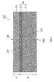
- FIG. 1 is a sectional view illustrating the configuration of the laminated body 100.
- the laminated body 100 is preferably used as an outer covering for an electronic device (digital camera, IC recorder, or the like).
- the laminated body 100 is formed in a tabular configuration.
- the laminated body 100 includes a first tabular member 10, and a second tabular member 20.
- the first tabular member 10 and the second tabular member 20 constitute a main body according to the present embodiment.
- the first tabular member 10 is formed in a tabular configuration.
- the first tabular member 10 includes a first outer surface 10S (an example of an outer surface), and a first inner surface 10T provided to face the first outer surface 10S.
- the first tabular member 10 is configured from a dense ceramic material that exhibits no more than 10% porosity.
- the ceramic material that configures the first tabular member 10 preferably includes use of a ceramic material with insulating properties that contains at least one of zirconia or alumina, or silicon nitride (Si 3 N 4 ), or the like.
- the ceramic material that configures the first tabular member 10 is not limited thereby. Due to its high mechanical strength and high toughness, use of a material having a principal constituent of partially stabilized zirconia in which yttrium oxide is added as a stabilizing agent to zirconia and the main crystalline phase is tetragonal is most preferred. In this configuration, the mechanical characteristics of the first tabular member 10 may be enhanced by addition of 2 to 6 mol% yttrium oxide to the zirconia.
- the ceramic material that configures the first tabular member 10 includes use of aluminum nitride (AlN), sialon (SiAlON), silicon carbonate (SiC), or the like.
- the first thickness t1 of the first tabular member 10 may be at least 50 micrometers and no more than 5 mm. When the first thickness t1 of the first tabular member 10 at least 50 micrometers, sufficient wear resistance is obtained in relation to use of a laminated body 100 as an outer covering material for an electronic device in which the first tabular member 10 is used on the outermost surface.
- the first outer surface 10S and the first inner surface 10T of the first tabular member 10 has an arithmetic mean roughness Ra of no more than 3 micrometers. Furthermore, it is preferred that the bonding force in relation to the second tabular member 20 (more specifically, the bonding surface 22 described below) of the first tabular member 10 is enhanced by causing the first inner surface 10T to be rougher than the first outer surface 10S. In order to enhance the wear resistance of the first tabular member 10, it is preferred that the arithmetic mean roughness Ra of the first outer surface 10S is no more than 0.1 micrometers.
- the second tabular member 20 is formed in a tabular configuration.
- the second tabular member 20 is bonded to the first tabular member 10.
- the second thickness t2 of the second tabular member 20 may be at least 20 micrometers and no more than 20 mm.
- the second tabular member 20 includes a second inner surface 20T and a second outer surface 20S.
- the second inner surface 20T is bonded to the first inner surface 10T of the first tabular member 10.
- the second outer surface 20S is provided to face the second inner surface 20T.
- the second tabular member 20 is configured by a supporting layer 21 and a bonding layer 22.
- the supporting layer 21 is fixed to the first tabular layer 10 by the bonding layer 22.
- the supporting layer 21 exhibits flexibility.
- the supporting layer 21 is configured from a polymer material.
- the polymer material that configures the supporting layer 21 preferably includes a fiber reinforced plastic.
- a fiber reinforced plastic is a material for example in which a resin such as an epoxy or nylon impregnated in a woven or non-woven fabric such as glass fiber, carbon fiber, aramid fiber, or the like is cured.
- the polymer material that configures the supporting layer 21 is not limited thereby, and includes use of polycarbonate, nylon, or the like.
- the bonding layer 22 is inserted between the first tabular member 10 and the supporting layer 21.
- the bonding layer 22 may be configured by a heat curable resin.
- the heat curable resin that configures the bonding layer 22 preferably includes use of a two-liquid type epoxy adhesive, a single-liquid type epoxy adhesive, a two-liquid type urethane adhesive, a two-liquid type olefin adhesive, a two-liquid type acrylic adhesive, or a single-liquid type acrylic adhesive.
- the bonding layer 22 may be configured by a thermoplastic resin, or the like.
- the thickness of the bonding layer 22 in order to stabilize the mechanical characteristics of the layered body 100 preferably is no more than 0.1 mm.
- the mechanical characteristics of the bonding layer 22 after curing are more preferably the same as the mechanical characteristics of the supporting layer 21.
- the laminated body 100 exhibits static load characteristics that are lower than a single layer body configured from the dense ceramic material that configures the first tabular member 10. That is to say, the strength of the laminated body 100 obtained from static load testing is smaller than the strength of the single layer body obtained from the same static load testing.
- the static load testing utilizes a so-called three point bending test (test piece dimensions: 2 mm x 20 mm, application point and distance between support point: 10 mm).
- the third thickness t3 of the single layer body is the sum of the thickness t1 of the first tabular body 10 and the second thickness t2 of the second tabular body 20.
- the laminated body 100 according to the present embodiment can withstand falling-ball impact breaking tests from a height that is higher than that exhibited by the single layer body as described above. That is to say, the impact load according to the laminated body 100 that is generated during impact with a ball can be reduced to lower than that exhibited by the single laminated body described above. In other words, the laminated body 100 can withstand an impact load that is greater than the ceramic single layer body. Therefore, the ball drop height that can be withstood by the laminated body 100 in the falling-ball impact breaking tests is higher than the ball drop height that can be withstood by the single layer body in the same falling-ball impact breaking tests.
- the falling-ball impact breaking tests comply with testing as specified by JIS (Japanese Industrial Standards) R 3206 or JIS K 6902.
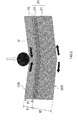
- FIG. 2 is a schematic view illustrating the position of the neutral plane U when the ball is dropped onto the laminated body 100 from a predetermined height.
- the distance P from the first outer surface 10S of the neutral plane U is obtained by Equation (1) below.
- Equation (1) Yi denotes the average Young's modulus of the first tabular member 10 and the second tabular member 20, and Ai denotes the multiple of the respective thickness and the width of the first tabular member 10 and the second tabular member 20.
- the average Young's modulus Y1 of the first tabular member 10 is preferably larger than the average Young's modulus Y2 of the second tabular member 20.
- the average Young's modulus Y1 of the first tabular member 10 may be 50 GPa to 500 GPa.
- the average Young's modulus Y2 of the second tabular member 20 may be 0.1 GPa to 100 GPa.
- the average Young's modulus Y2 of the second tabular member 20 is the average value of the Young's modulus of the supporting layer 21 and the Young's modulus of the bonding layer 22.
- the first thickness t1 of the first tabular member 10 may be at least 50 micrometers and no more than 5 mm.
- the second thickness t2 of the second tabular member 20 may be at least 200 micrometers and no more than 20 mm (the thickness is adjusted to the thickness t1 of the first tabular member 10).
- the distance P from the first outer surface of the neutral plane U is preferably at least 0.8 times the first thickness t1. That is to say, it is preferred that Equation (2) is satisfied between the distance P and the first thickness t1.
- the ball drop height that is withstood by the laminated body 100 in the falling-ball impact breaking test can be increased.
- the laminated body 100 is configured with a two layered structure including the first tabular member 10 and the second tabular member 20.
- the laminated body 100 may be configured with a multilayer structure of three or more layers.
- the first tabular member 10 may have a multilayer structure of more than two layers.
- the respective layers of the first tabular member 10 may be configured by a single ceramic material, or may be configured by a different ceramic in each layer.
- the second tabular member 20 may have a multilayer structure of more than two layers.
- the respective layers of the second tabular member 20 may be configured by a single polymer material, or may be configured by a different polymer in each layer.
- a ceramic plate (2 mm x 20 mm) configured from the material shown in Table 1 was prepared.
- the thickness and Young's modulus of the respective ceramic plates is shown in Table 1.
- the Comparative Examples 1 to 9 configure a ceramic-plate single layer body as a test piece for static load testing.
- a resin plate (2 mm x 20 mm) that is configured from the polymer material shown in Table 1 is bonded to the ceramic plate according to Examples 1 to 14.
- the Young's modulus Y2 and the thickness t2 of each resin plate is shown in Table 1.
- An epoxy adhesive agent was used to bond the ceramic plate and the resin plate.
- the thickness of the epoxy adhesive agent after curing is 0.02 mm.
- Examples 1 to 14 use a test piece for static load tests that is configured from a laminated body of a ceramic plate and a resin plate.
- the test piece for static load tests is disposed equidistantly on two support rods that are fixed to positions separated by 10 mm, and a pressure member is pressed into the center until the test piece for static load tests becomes bent.
- the static load when the test piece for static load tests became bent is shown in Table 1.
- a ceramic plate ( ⁇ 40 mm) configured from the material shown in Table 1 is prepared.
- the Young's modulus and thickness of each ceramic plate is shown in Table 1.
- Comparative Examples 1 to 9 use a test piece for falling-ball impact breaking tests that is configured from a single layer body of only a ceramic plate.
- the resin plate ( ⁇ 40 mm) that is configured from the polymer material shown in Table 1 is bonded to the ceramic plate according to Examples 1 to 14.
- the thickness and the Young's modulus of the respective resin plates are shown in Table 1.
- the bonding of the ceramic plate and the resin plate is performed using an epoxy adhesive agent.
- the thickness of the epoxy adhesive agent after curing is 0.02 mm.
- Examples 1 to 14 use a test piece for falling-ball impact breaking testing that is configured from a laminated body including the ceramic plate and the resin plate.
- a steel ball (mass 20 g, pi 17 mm) is dropped onto the center of the test piece for falling-ball impact breaking testing and the height when the ceramic plate cracks and fractures is measured.
- the height when a fracture is produced in the test piece for falling-ball impact breaking testing is shown in Table 1.
- the details of the falling-ball impact breaking tests described above are executed in accordance with JIS R 3206 or JIS K 6902.
- the static load in Examples 1 to 14 is confirmed to be smaller than the static load in Comparative Examples 1 to 9.
- the static load in Example 5 is 55.8N and the static load in Example 11 is 33.1N, while the static load in Comparative Example 1 is 62.8N.
- the ball drop height in Examples 1 to 14 is confirmed to be higher than the ball drop height in Comparative Examples 1 to 9.
- the ball drop height in Example 5 is 79 cm and the ball drop height in Example 11 is 54 cm, while the ball drop height in Comparative Example 1 is 18 cm.
- Examples 1 to 11 and Example 14 could withstand a ball drop height of at least 40 cm. This is due to the suppression of the tensile stress applied to the ceramic plate as a result of a positioning on the interface side of the ceramic plate and the resin plate even when the neutral plane is in the ceramic plate.
- Examples 12 and 13 could not withstand a ball drop height of less than 40 cm. This is due to the fact that the tensile stress applied to the ceramic plate was increased as a result of a positioning of the neutral surface deep in the ceramic plate inner portion. Therefore, it was shown that it is preferable that the neutral plane is separated from the ceramic plate surface by at least 0.8 times the ceramic plate thickness in order to withstand a ball drop test from a predetermined height.
Landscapes
- Engineering & Computer Science (AREA)
- Ceramic Engineering (AREA)
- Chemical & Material Sciences (AREA)
- Materials Engineering (AREA)
- Structural Engineering (AREA)
- Organic Chemistry (AREA)
- Mechanical Engineering (AREA)
- Laminated Bodies (AREA)
Abstract
Description
- This application claims the benefit of priority from Japanese patent application number
JP-2012-201134 (filed on 13 September 2012 - The technology disclosed herein relates to a tabular laminated body.
- Generally, the outer covering of an electronic device (a digital camera, IC recorder, or the like) is configured by a synthetic resin that exhibits high strength and low weight (see Patent Literature 1).
-
- Patent Literature 1: Japanese Patent Application Laid-Open No.
2011-21127 - However, there is the problem that a synthetic-resin outer covering exhibits low wear resistance and low scratch resistance. In the context, it seemed like a good idea to use a ceramic material that exhibits high wear resistance and high scratch resistance as an outer covering material. However, due to the fact that ceramics are characterized by a tendency to fracture, when the outer covering is only configured from a ceramic material, there is a risk of fracture in the outer covering due to application of an impact force.
- In light of the circumstances described above, the technology disclosed herein has the object of providing a laminated body that exhibits impact resistance, wear resistance and scratch resistance, and which enables a reduction in weight together with a reduction in the dielectric constant.
- In accordance with one aspect of the technology disclosed herein, a laminated body includes a main body having a first tabular member and a second tabular member. The first tabular member is configured from a ceramic material and has a first thickness. The second tabular member is configured from a polymer material and has a second thickness. The main body is configured to withstand a falling-ball impact breaking test from a height that is higher than a height exhibited by a single layer body which is configured from the ceramic material. The single layer body has a thickness that is the sum of the first thickness and the second thickness.
- The technology disclosed herein provides a laminated body that exhibits impact resistance, wear resistance and scratch resistance, and which enables a reduction in weight together with a reduction in the dielectric constant.
- Referring now to the attached drawings which form a part of this original disclosure:
-
FIG. 1 is a sectional view illustrating the configuration of a laminated body; -
FIG. 2 is a schematic view illustrating the position of the neutral plane; -
FIG. 3A is a front view illustrating a method of testing static load; -
FIG. 3B is a side view illustrating a method of testing static load. - Selected embodiments will now be explained with reference to the drawings. It will be apparent to those skilled in the art from this disclosure that the following descriptions of the embodiments are provided for illustration only and not for the purpose of limiting the invention as defined by the appended claims and their equivalents.
- The configuration of the laminated
body 100 will be described making reference to the figures.FIG. 1 is a sectional view illustrating the configuration of the laminatedbody 100. - The laminated
body 100 is preferably used as an outer covering for an electronic device (digital camera, IC recorder, or the like). The laminatedbody 100 is formed in a tabular configuration. The laminatedbody 100 includes a firsttabular member 10, and a secondtabular member 20. The firsttabular member 10 and the secondtabular member 20 constitute a main body according to the present embodiment. - The first
tabular member 10 is formed in a tabular configuration. The firsttabular member 10 includes a firstouter surface 10S (an example of an outer surface), and a firstinner surface 10T provided to face the firstouter surface 10S. The firsttabular member 10 is configured from a dense ceramic material that exhibits no more than 10% porosity. - The ceramic material that configures the first
tabular member 10 preferably includes use of a ceramic material with insulating properties that contains at least one of zirconia or alumina, or silicon nitride (Si3N4), or the like. However the ceramic material that configures the firsttabular member 10 is not limited thereby. Due to its high mechanical strength and high toughness, use of a material having a principal constituent of partially stabilized zirconia in which yttrium oxide is added as a stabilizing agent to zirconia and the main crystalline phase is tetragonal is most preferred. In this configuration, the mechanical characteristics of the firsttabular member 10 may be enhanced by addition of 2 to 6 mol% yttrium oxide to the zirconia. - The ceramic material that configures the first
tabular member 10 includes use of aluminum nitride (AlN), sialon (SiAlON), silicon carbonate (SiC), or the like. The first thickness t1 of the firsttabular member 10 may be at least 50 micrometers and no more than 5 mm. When the first thickness t1 of the firsttabular member 10 at least 50 micrometers, sufficient wear resistance is obtained in relation to use of a laminatedbody 100 as an outer covering material for an electronic device in which the firsttabular member 10 is used on the outermost surface. - It is preferred that the first
outer surface 10S and the firstinner surface 10T of the firsttabular member 10 has an arithmetic mean roughness Ra of no more than 3 micrometers. Furthermore, it is preferred that the bonding force in relation to the second tabular member 20 (more specifically, thebonding surface 22 described below) of the firsttabular member 10 is enhanced by causing the firstinner surface 10T to be rougher than the firstouter surface 10S. In order to enhance the wear resistance of the firsttabular member 10, it is preferred that the arithmetic mean roughness Ra of the firstouter surface 10S is no more than 0.1 micrometers. - The second
tabular member 20 is formed in a tabular configuration. The secondtabular member 20 is bonded to the firsttabular member 10. The second thickness t2 of the secondtabular member 20 may be at least 20 micrometers and no more than 20 mm. The secondtabular member 20 includes a secondinner surface 20T and a secondouter surface 20S. The secondinner surface 20T is bonded to the firstinner surface 10T of the firsttabular member 10. The secondouter surface 20S is provided to face the secondinner surface 20T. - In the present embodiment, the second
tabular member 20 is configured by a supportinglayer 21 and abonding layer 22. - The supporting
layer 21 is fixed to the firsttabular layer 10 by thebonding layer 22. The supportinglayer 21 exhibits flexibility. The supportinglayer 21 is configured from a polymer material. The polymer material that configures the supportinglayer 21 preferably includes a fiber reinforced plastic. A fiber reinforced plastic is a material for example in which a resin such as an epoxy or nylon impregnated in a woven or non-woven fabric such as glass fiber, carbon fiber, aramid fiber, or the like is cured. However, the polymer material that configures the supportinglayer 21 is not limited thereby, and includes use of polycarbonate, nylon, or the like. - The
bonding layer 22 is inserted between the firsttabular member 10 and the supportinglayer 21. Thebonding layer 22 may be configured by a heat curable resin. The heat curable resin that configures thebonding layer 22 preferably includes use of a two-liquid type epoxy adhesive, a single-liquid type epoxy adhesive, a two-liquid type urethane adhesive, a two-liquid type olefin adhesive, a two-liquid type acrylic adhesive, or a single-liquid type acrylic adhesive. However, there is no limitation in this regard. Thebonding layer 22 may be configured by a thermoplastic resin, or the like. The thickness of thebonding layer 22 in order to stabilize the mechanical characteristics of thelayered body 100 preferably is no more than 0.1 mm. The mechanical characteristics of thebonding layer 22 after curing are more preferably the same as the mechanical characteristics of the supportinglayer 21. - The
laminated body 100 according to the present embodiment exhibits static load characteristics that are lower than a single layer body configured from the dense ceramic material that configures the firsttabular member 10. That is to say, the strength of thelaminated body 100 obtained from static load testing is smaller than the strength of the single layer body obtained from the same static load testing. The static load testing utilizes a so-called three point bending test (test piece dimensions: 2 mm x 20 mm, application point and distance between support point: 10 mm). The third thickness t3 of the single layer body is the sum of the thickness t1 of the firsttabular body 10 and the second thickness t2 of the secondtabular body 20. - The
laminated body 100 according to the present embodiment can withstand falling-ball impact breaking tests from a height that is higher than that exhibited by the single layer body as described above. That is to say, the impact load according to thelaminated body 100 that is generated during impact with a ball can be reduced to lower than that exhibited by the single laminated body described above. In other words, thelaminated body 100 can withstand an impact load that is greater than the ceramic single layer body. Therefore, the ball drop height that can be withstood by thelaminated body 100 in the falling-ball impact breaking tests is higher than the ball drop height that can be withstood by the single layer body in the same falling-ball impact breaking tests. The falling-ball impact breaking tests comply with testing as specified by JIS (Japanese Industrial Standards) R 3206 or JIS K 6902. - The position of the neutral plane U of the
laminated body 100 will be described below making reference to the figures.FIG. 2 is a schematic view illustrating the position of the neutral plane U when the ball is dropped onto thelaminated body 100 from a predetermined height. The distance P from the firstouter surface 10S of the neutral plane U is obtained by Equation (1) below.
- In Equation (1), Yi denotes the average Young's modulus of the first
tabular member 10 and the secondtabular member 20, and Ai denotes the multiple of the respective thickness and the width of the firsttabular member 10 and the secondtabular member 20. - The average Young's modulus Y1 of the first
tabular member 10 is preferably larger than the average Young's modulus Y2 of the secondtabular member 20. The average Young's modulus Y1 of the firsttabular member 10 may be 50 GPa to 500 GPa. The average Young's modulus Y2 of the secondtabular member 20 may be 0.1 GPa to 100 GPa. In the present embodiment, the average Young's modulus Y2 of the secondtabular member 20 is the average value of the Young's modulus of the supportinglayer 21 and the Young's modulus of thebonding layer 22. - As described above, the first thickness t1 of the first
tabular member 10 may be at least 50 micrometers and no more than 5 mm. The second thickness t2 of the secondtabular member 20 may be at least 200 micrometers and no more than 20 mm (the thickness is adjusted to the thickness t1 of the first tabular member 10). - The distance P from the first outer surface of the neutral plane U is preferably at least 0.8 times the first thickness t1. That is to say, it is preferred that Equation (2) is satisfied between the distance P and the first thickness t1.

- In this manner, the ball drop height that is withstood by the
laminated body 100 in the falling-ball impact breaking test can be increased. - The present invention is not limited to the above embodiments, and various modifications and changes may be made within a scope that does not depart from the scope of the present invention.
- For example, in the above embodiment, the
laminated body 100 is configured with a two layered structure including the firsttabular member 10 and the secondtabular member 20. However there is no limitation in this regard. Thelaminated body 100 may be configured with a multilayer structure of three or more layers. - In the above embodiment, although a single layer structure was described in relation to the first
tabular member 10, there is no limitation in this regard. The firsttabular member 10 may have a multilayer structure of more than two layers. In this configuration, the respective layers of the firsttabular member 10 may be configured by a single ceramic material, or may be configured by a different ceramic in each layer. - In the above embodiment, although a single layer structure was described in relation to the second
tabular member 20, there is no limitation in this regard. The secondtabular member 20 may have a multilayer structure of more than two layers. In this configuration, the respective layers of the secondtabular member 20 may be configured by a single polymer material, or may be configured by a different polymer in each layer.
Thus, the present invention of course includes various embodiments and the like that are not discussed herein. Therefore, the technological scope of the present invention is not limited to just the specific inventions pertaining to the appropriate claims from the descriptions given above. - Although the examples related to the present invention will be described below, the present invention is not limited to the examples described below.
- Firstly, a ceramic plate (2 mm x 20 mm) configured from the material shown in Table 1 was prepared. The thickness and Young's modulus of the respective ceramic plates is shown in Table 1. The Comparative Examples 1 to 9 configure a ceramic-plate single layer body as a test piece for static load testing.
- Next, a resin plate (2 mm x 20 mm) that is configured from the polymer material shown in Table 1 is bonded to the ceramic plate according to Examples 1 to 14. The Young's modulus Y2 and the thickness t2 of each resin plate is shown in Table 1. An epoxy adhesive agent was used to bond the ceramic plate and the resin plate. The thickness of the epoxy adhesive agent after curing is 0.02 mm. Examples 1 to 14 use a test piece for static load tests that is configured from a laminated body of a ceramic plate and a resin plate.
- Next, as illustrated in
FIG. 3A and FIG. 3B , the test piece for static load tests is disposed equidistantly on two support rods that are fixed to positions separated by 10 mm, and a pressure member is pressed into the center until the test piece for static load tests becomes bent. The static load when the test piece for static load tests became bent is shown in Table 1. - A ceramic plate (□40 mm) configured from the material shown in Table 1 is prepared. The Young's modulus and thickness of each ceramic plate is shown in Table 1. Comparative Examples 1 to 9 use a test piece for falling-ball impact breaking tests that is configured from a single layer body of only a ceramic plate.
- Next, the resin plate (□40 mm) that is configured from the polymer material shown in Table 1 is bonded to the ceramic plate according to Examples 1 to 14. The thickness and the Young's modulus of the respective resin plates are shown in Table 1. The bonding of the ceramic plate and the resin plate is performed using an epoxy adhesive agent. The thickness of the epoxy adhesive agent after curing is 0.02 mm. Examples 1 to 14 use a test piece for falling-ball impact breaking testing that is configured from a laminated body including the ceramic plate and the resin plate.
- Next, a steel ball (mass 20 g, pi 17 mm) is dropped onto the center of the test piece for falling-ball impact breaking testing and the height when the ceramic plate cracks and fractures is measured. The height when a fracture is produced in the test piece for falling-ball impact breaking testing is shown in Table 1. The details of the falling-ball impact breaking tests described above are executed in accordance with JIS R 3206 or JIS K 6902.
Table 1 TEST PIECE CERAMIC PLATE RESIN PLATE The distance P of the first outer surface of the neutral plane The position of the neutral surface Total thickness Static load Ball drop height MATERIAL Young's modulus Y1 Thickness t1 MATERIAL Young's modulus Y2 Thickness t2 (GPa) (mm) (GPa) (mm) (mm) (P/t1) (mm) (N) (cm) Example 1 ZrO1 80%+Al2O3 20% 252 0.15 Glass epoxy(EPOXY/GF) 23 0.50 0.154 1.13 0.67 62.3 81 Example 2 ZrO2 80%+Al2O3 20% 252 0.15 Glass epoxy(EPOXY/GF) 23 0.60 0.179 1.31 0.77 78.0 124 Example 3 ZrO2 80%+Al2O3 20% 252 0.15 Nylon66/CF 28 0.50 0.167 1.22 0.67 52.1 56 Example 4 ZrO2 80%+Al2O3 20% 252 0.15 Nylon66/CF 20 0.50 0.146 1.06 0.67 56.6 67 Example 5 ZrO2 80%+Al2O3 20% 252 0.15 EPOXY/CF 60 0.40 0.188 1.41 0.57 55.8 79 Example 6 ZrO2 80%+Al2O3 20% 252 0.10 Glass epoxy(EPOXY/GF) 23 0.50 0.149 1.68 0.62 53.4 60 Example 7 ZrO2 80%+Al2O3 20% 252 0.20 Glass epoxy(EPOXY/GF) 23 0.60 0.189 1.01 0.82 43.5 60 Example 8 ZrO2 80%+Al2O3 20% 252 0.25 Glass epoxy(EPOXY/GF) 23 0.60 0.204 0.86 0.87 102.3 ≧ 200 Example 9 ZrO2 200 0.15 Glass epoxy(EPOXY/GF) 23 0.50 0.169 1.24 0.67 46.9 107 Example 10 Si3N4 300 0.15 Glass epoxy(EPOXY/GF) 23 0.50 0.144 1.05 0.67 56.0 65 Example 11 ZrO2 80%+Al2O3 20% 252 0.05 Glass epoxy(EPOXY/GF) 23 0.50 0.163 3.85 0.57 33.1 54 Example 12 ZrO2 80%+Al2O3 20% 252 0.20 Nylon66/CF 20 0.40 0.143 0.76 0.62 43.0 26 Example 13 ZrO2 80%+Al2O3 20% 252 0.30 Glass epoxy(EPOXY/GF) 23 0.50 0.205 0.71 0.82 68.3 34 Example 14 ZrO2 80%+Al2O3 20% 252 0.45 Glass epoxy(EPOXY/GF) 23 1.50 0.456 1.05 1.97 327.5 ≧ 200 Comparative Example 1 ZrO2 80%+Al2O3 20% 252 0.57 - - - - - 0.57 62.8 18 Comparative Example 2 ZrO2 80%+Al2O3 20% 252 0.62 - - - - - 0.62 67.6 21 Comparative Example 3 ZrO2 80%+Al2O3 20% 252 0.67 - - - - - 0.67 82.3 26 Comparative Example 4 ZrO2 80%+Al2O3 20% 252 0.77 - - - - - 0.77 96.4 29 Comparative Example 5 ZrO2 80%+Al2O3 20% 252 0.82 - - - - - 0.82 107.0 31 Comparative Example 6 ZrO2 80%+Al2O3 20% 252 0.87 - - - - - 0.87 125.2 40 Comparative Example 7 ZrO2 80%+Al2O3 20% 252 1.97 - - - - - 1.97 513.8 171 Comparative Example 8 ZrO2 200 0.67 - - - - - 0.67 76.3 26 Comparative Example 9 Si3N4 300 0.67 - - - - - 0.67 77.6 31 - As shown in Table 1, when the total thickness is the same, the static load in Examples 1 to 14 is confirmed to be smaller than the static load in Comparative Examples 1 to 9. For example, when test pieces with a total thickness of 0.57 mm are considered, the static load in Example 5 is 55.8N and the static load in Example 11 is 33.1N, while the static load in Comparative Example 1 is 62.8N.
- Furthermore, as shown in Table 1, when the total thickness is the same, the ball drop height in Examples 1 to 14 is confirmed to be higher than the ball drop height in Comparative Examples 1 to 9. For example, when test pieces with a total thickness of 0.57 mm are considered, the ball drop height in Example 5 is 79 cm and the ball drop height in Example 11 is 54 cm, while the ball drop height in Comparative Example 1 is 18 cm.
- As shown in Table 1, Examples 1 to 11 and Example 14 could withstand a ball drop height of at least 40 cm. This is due to the suppression of the tensile stress applied to the ceramic plate as a result of a positioning on the interface side of the ceramic plate and the resin plate even when the neutral plane is in the ceramic plate. On the other hand, Examples 12 and 13 could not withstand a ball drop height of less than 40 cm. This is due to the fact that the tensile stress applied to the ceramic plate was increased as a result of a positioning of the neutral surface deep in the ceramic plate inner portion. Therefore, it was shown that it is preferable that the neutral plane is separated from the ceramic plate surface by at least 0.8 times the ceramic plate thickness in order to withstand a ball drop test from a predetermined height.
-
- 10
- FIRST TABULAR MEMBER
- 10S
- FIRST OUTER SURFACE
- 20
- SECOND TABULAR MEMBER
- 20S
- SECOND OUTER SURFACE
- 21
- SUPPORTING LAYER
- 22
- BONDING LAYER
- 100
- LAMINATED BODY
Claims (9)
- A laminated body comprising:a main body includes a first tabular member and a second tabular member, the first tabular member configured from a ceramic material and having a first thickness, the second tabular member configured from a polymer material and having a second thickness,the main body configured to withstand a falling-ball impact breaking test from a height that is higher than a height exhibited by a single layer body which is configured from the ceramic material and of a thickness that is the sum of the first thickness and the second thickness.
- The laminated body according to claim 1, wherein
the first tabular member includes an outer surface, and
a neutral plane of the main body is separated by at least 0.8 times the first thickness from the outer surface. - The laminated body according to claim 1 or 2, wherein the first tabular member is at least 50 micrometers.
- The laminated body according to claim 2 or 3, wherein an average Young's modulus of the first tabular member is larger than an average Young's modulus of the second tabular member.
- The laminated body according to claim 4, wherein
a distance of the neutral plane from the outer surface is given by Equation 1 below.
[Equation 1]
(Wherein, in Equation 1, Yi denotes the average Young's modulus of the first tabular member and the second tabular member, and Ai denotes the multiple of the respective thickness and the width of the first tabular member and the second tabular member.) - The laminated body according to any one of claim 1 to claim 5, wherein
the first tabular member is configured by at least one of zirconia and alumina. - The laminated body according to any one of claim 1 to claim 6, wherein
the second tabular member comprises a flexible supporting layer and a bonding layer which is interposed between the supporting layer and the first tabular member. - The laminated body according to claim 7, wherein
the supporting layer is configured by a fiber reinforced plastic. - The laminated body according to any one of claim 1 to claim 8, wherein
the main body configured to have static load characteristics that are lower than the single layer body of the thickness that is the sum of the first thickness and the second thickness.
Applications Claiming Priority (1)
| Application Number | Priority Date | Filing Date | Title |
|---|---|---|---|
| JP2012201134A JP5956294B2 (en) | 2012-09-13 | 2012-09-13 | Laminated body |
Publications (1)
| Publication Number | Publication Date |
|---|---|
| EP2708475A1 true EP2708475A1 (en) | 2014-03-19 |
Family
ID=49118391
Family Applications (1)
| Application Number | Title | Priority Date | Filing Date |
|---|---|---|---|
| EP13183488.9A Withdrawn EP2708475A1 (en) | 2012-09-13 | 2013-09-09 | Laminated body |
Country Status (3)
| Country | Link |
|---|---|
| US (1) | US9481147B2 (en) |
| EP (1) | EP2708475A1 (en) |
| JP (1) | JP5956294B2 (en) |
Families Citing this family (6)
| Publication number | Priority date | Publication date | Assignee | Title |
|---|---|---|---|---|
| JP6252113B2 (en) * | 2013-11-06 | 2017-12-27 | 東ソー株式会社 | Composite plate and manufacturing method thereof |
| KR102713092B1 (en) * | 2017-01-03 | 2024-10-07 | 삼성전자주식회사 | Ceramic plate and refrigerator including thereof |
| JP7120240B2 (en) * | 2017-08-29 | 2022-08-17 | 東亞合成株式会社 | Resin sheet and curable composition for producing same |
| KR102414084B1 (en) * | 2017-10-11 | 2022-06-28 | 코닝 인코포레이티드 | Foldable electronic device modules with impact resistance and bending resistance |
| TW201935039A (en) | 2018-01-25 | 2019-09-01 | 美商康寧公司 | Fiberglass composite cover for foldable electronic display and methods of making the same |
| CN116952705B (en) * | 2023-09-19 | 2024-02-20 | 中铁十七局集团第五工程有限公司 | Structural bionic basalt fiber reinforced composite material impact resistance detection device |
Citations (3)
| Publication number | Priority date | Publication date | Assignee | Title |
|---|---|---|---|---|
| US20020033114A1 (en) * | 2000-01-26 | 2002-03-21 | Asahi Glass Company, Limited | Antifouling paint composition and product coated therewith |
| US7642206B1 (en) * | 2006-03-24 | 2010-01-05 | Honeywell International Inc. | Ceramic faced ballistic panel construction |
| JP2011021127A (en) | 2009-07-16 | 2011-02-03 | Idemitsu Kosan Co Ltd | Housing for portable electronic appliance |
Family Cites Families (8)
| Publication number | Priority date | Publication date | Assignee | Title |
|---|---|---|---|---|
| US5330820A (en) * | 1989-07-13 | 1994-07-19 | Alliedsignal Inc. | Ballistic resistant composition article having improved matrix system |
| JPH0664076A (en) * | 1992-08-20 | 1994-03-08 | Tonen Corp | Composite plate material and method for manufacturing the same |
| JP3127947B2 (en) | 1994-09-06 | 2001-01-29 | 住友ベークライト株式会社 | Composite molding |
| JP2005254487A (en) | 2004-03-09 | 2005-09-22 | Toray Ind Inc | Impact resistant fiber reinforced plastics and multilayer laminates |
| JP4869915B2 (en) | 2006-12-28 | 2012-02-08 | 京セラケミカル株式会社 | Compound bulletproof board |
| JP2009028944A (en) | 2007-07-25 | 2009-02-12 | Toray Ind Inc | Ballistic protection members and ballistic protection products |
| JP2009121774A (en) * | 2007-11-16 | 2009-06-04 | Kyocera Chemical Corp | Composite bulletproof plate |
| JP5405844B2 (en) * | 2009-02-02 | 2014-02-05 | 株式会社日本セラテック | Impact resistant material |
-
2012
- 2012-09-13 JP JP2012201134A patent/JP5956294B2/en active Active
-
2013
- 2013-09-06 US US14/019,820 patent/US9481147B2/en active Active
- 2013-09-09 EP EP13183488.9A patent/EP2708475A1/en not_active Withdrawn
Patent Citations (3)
| Publication number | Priority date | Publication date | Assignee | Title |
|---|---|---|---|---|
| US20020033114A1 (en) * | 2000-01-26 | 2002-03-21 | Asahi Glass Company, Limited | Antifouling paint composition and product coated therewith |
| US7642206B1 (en) * | 2006-03-24 | 2010-01-05 | Honeywell International Inc. | Ceramic faced ballistic panel construction |
| JP2011021127A (en) | 2009-07-16 | 2011-02-03 | Idemitsu Kosan Co Ltd | Housing for portable electronic appliance |
Also Published As
| Publication number | Publication date |
|---|---|
| JP5956294B2 (en) | 2016-07-27 |
| US9481147B2 (en) | 2016-11-01 |
| US20140072785A1 (en) | 2014-03-13 |
| JP2014054780A (en) | 2014-03-27 |
Similar Documents
| Publication | Publication Date | Title |
|---|---|---|
| US9481147B2 (en) | Laminated body | |
| KR102563749B1 (en) | Window for display device and display device comprising thereof | |
| EP2930018B1 (en) | Composite plate and method for producing same | |
| AU2011326249B2 (en) | Insert molding around glass members for portable electronic devices | |
| US10387707B2 (en) | Reinforcement panel for fingerprint sensor cover | |
| CN108779018A (en) | Flexible electronic-component module, product and manufacture its adhesive method | |
| KR102237334B1 (en) | Glass film-resin composite | |
| TW201437011A (en) | Methods of forming strengthened sintered glass structures | |
| CN107211527A (en) | Semi-flexible printed circuit board (PCB) with embedded components | |
| JP2016210023A (en) | Method for manufacturing flexible laminate | |
| JPWO2009142238A1 (en) | Sintered body, manufacturing method thereof, and optical component | |
| US20150024165A1 (en) | Transparent armor construction | |
| KR20150032675A (en) | Composite plate and production method therefor | |
| WO2011122416A1 (en) | Piezoelectric-element-using device | |
| JP6237130B2 (en) | Composite plate and manufacturing method thereof | |
| CN111312075A (en) | Display device, manufacturing method thereof, display screen and cover plate | |
| JP2002543441A (en) | Piezoelectric strain gauge | |
| CN108648622A (en) | Display terminal and its display screen | |
| JP2009065129A (en) | Frame for wafer | |
| KR102041970B1 (en) | Heat radiating sheet integrated digitizer and display device comprising the same | |
| KR101699305B1 (en) | Tempered Glass for Mobile Devices | |
| KR102437590B1 (en) | Heat radiation sheet and EMI shielding-Heat radiation composite sheet comprising the same | |
| EP3961694B1 (en) | Electronic component module and silicon nitride circuit substrate | |
| KR20190059301A (en) | Method for producing film laminate | |
| JP4522890B2 (en) | Board mounting method using sheet unit for printed wiring board |
Legal Events
| Date | Code | Title | Description |
|---|---|---|---|
| PUAI | Public reference made under article 153(3) epc to a published international application that has entered the european phase |
Free format text: ORIGINAL CODE: 0009012 |
|
| AK | Designated contracting states |
Kind code of ref document: A1 Designated state(s): AL AT BE BG CH CY CZ DE DK EE ES FI FR GB GR HR HU IE IS IT LI LT LU LV MC MK MT NL NO PL PT RO RS SE SI SK SM TR |
|
| AX | Request for extension of the european patent |
Extension state: BA ME |
|
| 17P | Request for examination filed |
Effective date: 20140815 |
|
| RBV | Designated contracting states (corrected) |
Designated state(s): AL AT BE BG CH CY CZ DE DK EE ES FI FR GB GR HR HU IE IS IT LI LT LU LV MC MK MT NL NO PL PT RO RS SE SI SK SM TR |
|
| 17Q | First examination report despatched |
Effective date: 20151124 |
|
| STAA | Information on the status of an ep patent application or granted ep patent |
Free format text: STATUS: THE APPLICATION IS DEEMED TO BE WITHDRAWN |
|
| 18D | Application deemed to be withdrawn |
Effective date: 20160607 |