EP2708418A1 - Vehicle - Google Patents
Vehicle Download PDFInfo
- Publication number
- EP2708418A1 EP2708418A1 EP12184160.5A EP12184160A EP2708418A1 EP 2708418 A1 EP2708418 A1 EP 2708418A1 EP 12184160 A EP12184160 A EP 12184160A EP 2708418 A1 EP2708418 A1 EP 2708418A1
- Authority
- EP
- European Patent Office
- Prior art keywords
- vehicle
- profile
- service step
- mudguards
- engine compartment
- Prior art date
- Legal status (The legal status is an assumption and is not a legal conclusion. Google has not performed a legal analysis and makes no representation as to the accuracy of the status listed.)
- Withdrawn
Links
- 238000011161 development Methods 0.000 description 4
- 230000018109 developmental process Effects 0.000 description 4
- 239000002184 metal Substances 0.000 description 3
- XLYOFNOQVPJJNP-UHFFFAOYSA-N water Substances O XLYOFNOQVPJJNP-UHFFFAOYSA-N 0.000 description 2
- 230000015572 biosynthetic process Effects 0.000 description 1
- 210000003127 knee Anatomy 0.000 description 1
- 238000012423 maintenance Methods 0.000 description 1
Images
Classifications
-
- B—PERFORMING OPERATIONS; TRANSPORTING
- B62—LAND VEHICLES FOR TRAVELLING OTHERWISE THAN ON RAILS
- B62D—MOTOR VEHICLES; TRAILERS
- B62D25/00—Superstructure or monocoque structure sub-units; Parts or details thereof not otherwise provided for
- B62D25/08—Front or rear portions
- B62D25/16—Mud-guards or wings; Wheel cover panels
- B62D25/168—Mud guards for utility vehicles
-
- B—PERFORMING OPERATIONS; TRANSPORTING
- B60—VEHICLES IN GENERAL
- B60R—VEHICLES, VEHICLE FITTINGS, OR VEHICLE PARTS, NOT OTHERWISE PROVIDED FOR
- B60R3/00—Arrangements of steps or ladders facilitating access to or on the vehicle, e.g. running-boards
Definitions
- the present invention relates to a vehicle with an engine compartment positioned between at least two front wheels.
- the vehicle includes mudguards positioned above the wheels and a hinged driver cabin positioned above the engine compartment and the mudguards.
- This type of vehicles is known and widely used, particularly for the transport of goods.
- the driving cabin can be tilted so that the engine compartment becomes accessible for a mechanic.
- US 4,610,456 A discloses a service step for use on a two-wheel drive tractor of the wide front axle type.
- the step is mounted on a knee portion below the front axle.
- An inventive vehicle includes at least two front wheels, an engine compartment positioned between the front wheels, mudguards positioned above the front wheels, a hinged driver cabin positioned above the engine compartment and the mudguards, and at least one service step that is so designed as to be suitable for standing on it.
- the at least one service step is located on top of a mudguard.
- a service step that is so designed as to be suitable for standing on it can be located on top of each of the mudguards of the front wheels.
- the service step provides a convenient and safe foothold for a mechanic when servicing the engine.
- the maintenance and the service of the engine of the vehicle can be improved in terms of ergonomics since access to the engine compartment will be easier and more comfortable.
- the increased ergonomics helps to reduce service time and to prevent occupational accidents. Crashes of mudguards caused by stepping on it can also be prevented.
- the service step and the mudguard may be mounted to same support structure. Thus, no additional support structure is necessary for holding the service step.
- the service step may include a profile forming a platform, where the profile may advantageously be made of metal.
- the profile may include gutters.
- the profile may include holes. Water can drain through the holes so that the platform formed by the profile can be prevented from becoming slippery.
- the profile may be mounted to the support structure by use of adapters.
- Adapters allow mounting the same type of profile to different support structures. Moreover, adapters also allow reducing storage costs since only different adapters need to be stored instead of a large number mounting steps with different mounting means.
- the profile may be fixed on the adapters by bolts and weld nuts whereby a very fast and economical assembly is possible.
- the adapters may be welded to the support structure.
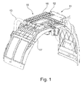
- Fig. 1 shows a mudguard 17 including a service step 11 positioned on the mudguard 17
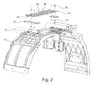
- Fig. 2 shows the mudguard 17 and an exploded view of the service step 11 in more detail.
- the service step 11 comprises a metal profile 12 which forms a platform 16 suitable for standing on it. Width and length of the profile 12 is designed according to feet of a standard person.
- the profile 12 includes gutters 24 to achieve a higher rigidity of the platform 16. In addition, the gutters 24 generate more foothold for a mechanic.
- the profile 12 also includes holes 18 through which water can drain. This prevents the formation of puddles on the platform 16 which could make the platform slippery. Moreover, the holes 18 also increase the foothold.
- the service step 11 is fixed to the support structure that also holds the mudguard 17 and the wheel house liner, e.g. to support arms 13.
- the service step 11 is fixed the tube brackets 13.
- the service step 11 of the present embodiment also includes adapters 14 which are located between the tube brackets 13 and the profile 12.
- the profile 12 is fixed to the adapters 14 by means of bolts 15 and weld nuts 19.
- the profile 12 is fixed to the adapters 14 by means of bolts 15 and weld nuts 19 in the present embodiment
- other means for fixing the service step 11 to the adapters are also feasible, for example rivets or screws.
- the adapters 14 are implemented as sheet metal brackets and are welded to the tube brackets 13.
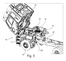
- Fig. 3 shows an embodiment of the inventive vehicle 10 with a service step 11.
- the vehicle includes a driver cabin 21, a frame 20, and at least four wheels 22 (which are not all visible in Figure 3 ).
- An engine compartment 23 is disposed between the two front wheels 22 of the vehicle 10.
- the driver cabin 21 is located above the engine compartment 23.
- the service step 11 can also be reached after the driving cabin 21 has been tilted forward.
- the service step 11 is positioned above a front wheel 22 on the top of the respective mudguard 17, which also forms the wheel house. It is advantageous if a service step 11 is present on top of each mudguard 17 of a front wheel 22.
- the mudguards 17 and the service steps 11 are fixed to the frame 20 of the vehicle 10 by means of tube brackets 13, as described above.
Landscapes
- Engineering & Computer Science (AREA)
- Mechanical Engineering (AREA)
- Chemical & Material Sciences (AREA)
- Combustion & Propulsion (AREA)
- Transportation (AREA)
- Body Structure For Vehicles (AREA)
Abstract
Description
- The present invention relates to a vehicle with an engine compartment positioned between at least two front wheels. The vehicle includes mudguards positioned above the wheels and a hinged driver cabin positioned above the engine compartment and the mudguards.
- This type of vehicles is known and widely used, particularly for the transport of goods. To carry out work in the engine compartment the driving cabin can be tilted so that the engine compartment becomes accessible for a mechanic. However, it is hard to find a safe foothold next to the opened engine compartment for a mechanic.
-
US 4,610,456 A discloses a service step for use on a two-wheel drive tractor of the wide front axle type. The step is mounted on a knee portion below the front axle. - It is an objective of the present invention to provide a vehicle with a tiltable driver compartment which includes an advantageous foothold for a mechanist carrying out work in the engine compartment.
- According to the present invention, this objective is achieved by a vehicle as claimed in claim 1. The depending claims contain further developments of the invention.
- An inventive vehicle includes at least two front wheels, an engine compartment positioned between the front wheels, mudguards positioned above the front wheels, a hinged driver cabin positioned above the engine compartment and the mudguards, and at least one service step that is so designed as to be suitable for standing on it. The at least one service step is located on top of a mudguard. In particular, a service step that is so designed as to be suitable for standing on it can be located on top of each of the mudguards of the front wheels.
- The service step provides a convenient and safe foothold for a mechanic when servicing the engine. Thereby, the maintenance and the service of the engine of the vehicle can be improved in terms of ergonomics since access to the engine compartment will be easier and more comfortable. The increased ergonomics helps to reduce service time and to prevent occupational accidents. Crashes of mudguards caused by stepping on it can also be prevented.
- In the context of the present invention, the service step and the mudguard may be mounted to same support structure. Thus, no additional support structure is necessary for holding the service step.
- In a development of the present invention the service step may include a profile forming a platform, where the profile may advantageously be made of metal. By this measure, a simple and cost effective design becomes possible.
- In a further development of the present invention the profile may include gutters. By this measure, a higher stiffness and rigidity can be achieved.
- In a still further development of the present invention the profile may include holes. Water can drain through the holes so that the platform formed by the profile can be prevented from becoming slippery.
- In a particular embodiment of the present invention the profile may be mounted to the support structure by use of adapters. Adapters allow mounting the same type of profile to different support structures. Moreover, adapters also allow reducing storage costs since only different adapters need to be stored instead of a large number mounting steps with different mounting means. The profile may be fixed on the adapters by bolts and weld nuts whereby a very fast and economical assembly is possible. The adapters may be welded to the support structure.
- Further features, properties and advantages of the present invention will become clear from the following description of embodiments in conjunction with the accompanying drawings.
- Figure 1
- shows a service step on a mudguard of a vehicle in a perspective view.
- Figure 2
- shows the mudguard of
Figure 1 with the service step in an exploded view. - Figure 3
- shows a vehicle with the driver cabin tilted and service steps on the mudguards of the front wheels.
- The present invention will now be described, by way of example, with reference to the accompanying drawings, in which
Fig. 1 shows amudguard 17 including aservice step 11 positioned on themudguard 17 andFig. 2 shows themudguard 17 and an exploded view of theservice step 11 in more detail. - In the shown embodiment, the
service step 11 comprises ametal profile 12 which forms aplatform 16 suitable for standing on it. Width and length of theprofile 12 is designed according to feet of a standard person. Theprofile 12 includesgutters 24 to achieve a higher rigidity of theplatform 16. In addition, thegutters 24 generate more foothold for a mechanic. Theprofile 12 also includesholes 18 through which water can drain. This prevents the formation of puddles on theplatform 16 which could make the platform slippery. Moreover, theholes 18 also increase the foothold. - In the present embodiment, the
service step 11 is fixed to the support structure that also holds themudguard 17 and the wheel house liner, e.g. to supportarms 13. Thesupport arms 13, which are formed by tube brackets in the present embodiment, connect themudguard 17 and the wheel house liner to avehicle frame 20, as shown inFig. 3 . Theservice step 11 is fixed thetube brackets 13. - The
service step 11 of the present embodiment also includesadapters 14 which are located between thetube brackets 13 and theprofile 12. Theprofile 12 is fixed to theadapters 14 by means ofbolts 15 andweld nuts 19. Although theprofile 12 is fixed to theadapters 14 by means ofbolts 15 andweld nuts 19 in the present embodiment other means for fixing theservice step 11 to the adapters are also feasible, for example rivets or screws. - The
adapters 14 are implemented as sheet metal brackets and are welded to thetube brackets 13. -
Fig. 3 shows an embodiment of theinventive vehicle 10 with aservice step 11. The vehicle includes adriver cabin 21, aframe 20, and at least four wheels 22 (which are not all visible inFigure 3 ). Anengine compartment 23 is disposed between the twofront wheels 22 of thevehicle 10. Thedriver cabin 21 is located above theengine compartment 23. To allow reaching theengine compartment 23 the drivingcabin 21 can be tilted forward about a hinge, as it is shown inFig. 3 . Theservice step 11 can also be reached after the drivingcabin 21 has been tilted forward. - The
service step 11 is positioned above afront wheel 22 on the top of therespective mudguard 17, which also forms the wheel house. It is advantageous if aservice step 11 is present on top of eachmudguard 17 of afront wheel 22. - The
mudguards 17 and theservice steps 11 are fixed to theframe 20 of thevehicle 10 by means oftube brackets 13, as described above. -
- 10
- Vehicle
- 11
- Service Step
- 12
- Profile
- 13
- Tube Bracket
- 14
- Adapter
- 15
- Bolts
- 16
- Platform
- 17
- Mudguard
- 18
- Holes
- 19
- Weld Nuts
- 20
- Frame
- 21
- Driver Cabin
- 22
- Wheel
- 23
- Engine Compartment
- 24
- Gutter
Claims (9)
- A vehicle (10) including at least two front wheels (22), an engine compartment (23) positioned between the front wheels (22), mudguards (17) positioned above the front wheels (22), a hinged driver cabin (21) positioned above the engine compartment (23) and the mudguards (17), and at least one service step (11) that is so designed as to be suitable for standing on it, wherein the at least one service step (11) is located on top of a mudguard (17).
- The vehicle (10) as claimed in claim 1, wherein the service step (11) and the mudguard (17) are mounted to the same support structure (13).
- The vehicle (10) as claimed in claim 1 or 2, wherein the service step (11) comprises a profile (12) to form a platform (16).
- The vehicle (10) as claimed in claim 3, wherein the profile (12) includes gutters (24).
- The vehicle (10) as claimed in claim 3 or 4, wherein the profile (12) includes holes (18).
- The vehicle (10) as claimed in any of the claims 3 to 5, wherein the profile (12) is connected to a support structure (13) by means of adapters (14).
- The vehicle (10) as claimed in claim 6, wherein the adapters (14) are welded to the support structure (13).
- The vehicle (10) as claimed in claim 6 or claim 7, wherein the profile (12) is fixed to the adapters (14) by bolts (15) and weld nuts (19).
- The vehicle as claimed in any one of the preceding claims, wherein a service step (11) that is so designed as to be suitable for standing on it is located on top of each of the mudguards (17) of the front wheel s.
Priority Applications (1)
| Application Number | Priority Date | Filing Date | Title |
|---|---|---|---|
| EP12184160.5A EP2708418A1 (en) | 2012-09-13 | 2012-09-13 | Vehicle |
Applications Claiming Priority (1)
| Application Number | Priority Date | Filing Date | Title |
|---|---|---|---|
| EP12184160.5A EP2708418A1 (en) | 2012-09-13 | 2012-09-13 | Vehicle |
Publications (1)
| Publication Number | Publication Date |
|---|---|
| EP2708418A1 true EP2708418A1 (en) | 2014-03-19 |
Family
ID=46881002
Family Applications (1)
| Application Number | Title | Priority Date | Filing Date |
|---|---|---|---|
| EP12184160.5A Withdrawn EP2708418A1 (en) | 2012-09-13 | 2012-09-13 | Vehicle |
Country Status (1)
| Country | Link |
|---|---|
| EP (1) | EP2708418A1 (en) |
Cited By (2)
| Publication number | Priority date | Publication date | Assignee | Title |
|---|---|---|---|---|
| CN116238605A (en) * | 2023-03-06 | 2023-06-09 | 徐工集团工程机械股份有限公司 | Load-bearing fender assembly and backhoe loader |
| CN119389113A (en) * | 2024-11-28 | 2025-02-07 | 东风商用车有限公司 | A climbing device and a vehicle cab thereof |
Citations (3)
| Publication number | Priority date | Publication date | Assignee | Title |
|---|---|---|---|---|
| US4610456A (en) | 1985-09-09 | 1986-09-09 | Deere & Company | Knee mounted service step for two-wheel drive tractor |
| EP0227962A1 (en) * | 1985-12-13 | 1987-07-08 | IVECO FIAT S.p.A. | Improved cab for an industrial vehicle |
| US6264222B1 (en) * | 1999-02-25 | 2001-07-24 | Freightliner Llc | Retractable stairway assembly for a vehicle |
-
2012
- 2012-09-13 EP EP12184160.5A patent/EP2708418A1/en not_active Withdrawn
Patent Citations (3)
| Publication number | Priority date | Publication date | Assignee | Title |
|---|---|---|---|---|
| US4610456A (en) | 1985-09-09 | 1986-09-09 | Deere & Company | Knee mounted service step for two-wheel drive tractor |
| EP0227962A1 (en) * | 1985-12-13 | 1987-07-08 | IVECO FIAT S.p.A. | Improved cab for an industrial vehicle |
| US6264222B1 (en) * | 1999-02-25 | 2001-07-24 | Freightliner Llc | Retractable stairway assembly for a vehicle |
Cited By (2)
| Publication number | Priority date | Publication date | Assignee | Title |
|---|---|---|---|---|
| CN116238605A (en) * | 2023-03-06 | 2023-06-09 | 徐工集团工程机械股份有限公司 | Load-bearing fender assembly and backhoe loader |
| CN119389113A (en) * | 2024-11-28 | 2025-02-07 | 东风商用车有限公司 | A climbing device and a vehicle cab thereof |
Similar Documents
| Publication | Publication Date | Title |
|---|---|---|
| US10821903B2 (en) | Modular rail and step system | |
| US8684382B2 (en) | Axle bracket for motor vehicles | |
| US8540307B2 (en) | Truck front end attachment mount | |
| US9187139B2 (en) | Truck front end attachment mount | |
| CN109562715B (en) | Vehicles with removable panel assemblies | |
| JP7176485B2 (en) | vehicle frame structure | |
| EP2855242B1 (en) | Vehicle structure comprising wing support with controlled deformation in the event of an impact | |
| CN103687779A (en) | Shaft support with integrated bracket for drives | |
| CN107010114B (en) | Vehicle frame including brackets for small offset rigid barrier testing | |
| WO2013142818A1 (en) | Semi trailor underrun protection | |
| WO2009155608A2 (en) | Apparatus, system, and method for accessing the engine compartment of a vehicle | |
| US20130043087A1 (en) | Motor vehicle body | |
| FR2914900A1 (en) | AUTOMOTIVE VEHICLE DASHBOARD TRAILER AND CORRESPONDING MOTOR VEHICLE. | |
| US20210039743A1 (en) | Cargo bicycle which can be driven using muscle power and/or an electric drive | |
| CN108058647A (en) | A kind of automobile side pedal and automobile | |
| EP1749710A3 (en) | Fender panel mounting structure of automobile | |
| US20240227941A1 (en) | Vehicle | |
| EP4237315B1 (en) | Motor vehicle front drive train comprising a cross-member extending between two shock-absorber cups | |
| CN104163193A (en) | Structure of a steering support member | |
| CN101456440B (en) | Reinforcement structure of motorcycle frame | |
| US20140319794A1 (en) | Vehicle step assembly | |
| US20040017057A1 (en) | Engine step | |
| WO2008139092A2 (en) | Adjustable crossbar for automobile dashboard and corresponding automobile | |
| US20160243991A1 (en) | Support Platform for a Truck | |
| CN109795398A (en) | A kind of tire service car |
Legal Events
| Date | Code | Title | Description |
|---|---|---|---|
| PUAI | Public reference made under article 153(3) epc to a published international application that has entered the european phase |
Free format text: ORIGINAL CODE: 0009012 |
|
| AK | Designated contracting states |
Kind code of ref document: A1 Designated state(s): AL AT BE BG CH CY CZ DE DK EE ES FI FR GB GR HR HU IE IS IT LI LT LU LV MC MK MT NL NO PL PT RO RS SE SI SK SM TR |
|
| AX | Request for extension of the european patent |
Extension state: BA ME |
|
| RAP1 | Party data changed (applicant data changed or rights of an application transferred) |
Owner name: FORD OTOMOTIV SANAYI ANONIM SIRKETI Owner name: FORD MOTOR COMPANY |
|
| 17P | Request for examination filed |
Effective date: 20140919 |
|
| RBV | Designated contracting states (corrected) |
Designated state(s): AL AT BE BG CH CY CZ DE DK EE ES FI FR GB GR HR HU IE IS IT LI LT LU LV MC MK MT NL NO PL PT RO RS SE SI SK SM TR |
|
| STAA | Information on the status of an ep patent application or granted ep patent |
Free format text: STATUS: THE APPLICATION IS DEEMED TO BE WITHDRAWN |
|
| 18D | Application deemed to be withdrawn |
Effective date: 20140920 |