EP2708288A2 - Precision pumping system for spray treatment cycles - Google Patents
Precision pumping system for spray treatment cycles Download PDFInfo
- Publication number
- EP2708288A2 EP2708288A2 EP13184687.5A EP13184687A EP2708288A2 EP 2708288 A2 EP2708288 A2 EP 2708288A2 EP 13184687 A EP13184687 A EP 13184687A EP 2708288 A2 EP2708288 A2 EP 2708288A2
- Authority
- EP
- European Patent Office
- Prior art keywords
- piston
- pump
- spray
- displaceable member
- controller
- Prior art date
- Legal status (The legal status is an assumption and is not a legal conclusion. Google has not performed a legal analysis and makes no representation as to the accuracy of the status listed.)
- Withdrawn
Links
Images


Classifications
-
- B—PERFORMING OPERATIONS; TRANSPORTING
- B05—SPRAYING OR ATOMISING IN GENERAL; APPLYING FLUENT MATERIALS TO SURFACES, IN GENERAL
- B05B—SPRAYING APPARATUS; ATOMISING APPARATUS; NOZZLES
- B05B12/00—Arrangements for controlling delivery; Arrangements for controlling the spray area
- B05B12/004—Arrangements for controlling delivery; Arrangements for controlling the spray area comprising sensors for monitoring the delivery, e.g. by displaying the sensed value or generating an alarm
-
- A—HUMAN NECESSITIES
- A61—MEDICAL OR VETERINARY SCIENCE; HYGIENE
- A61M—DEVICES FOR INTRODUCING MEDIA INTO, OR ONTO, THE BODY; DEVICES FOR TRANSDUCING BODY MEDIA OR FOR TAKING MEDIA FROM THE BODY; DEVICES FOR PRODUCING OR ENDING SLEEP OR STUPOR
- A61M35/00—Devices for applying media, e.g. remedies, on the human body
- A61M35/20—Non-portable devices, e.g. spraying booths
- A61M35/25—Non-portable devices, e.g. spraying booths specially adapted for the application of sunscreen, tanning or self-tanning lotions
-
- B—PERFORMING OPERATIONS; TRANSPORTING
- B05—SPRAYING OR ATOMISING IN GENERAL; APPLYING FLUENT MATERIALS TO SURFACES, IN GENERAL
- B05B—SPRAYING APPARATUS; ATOMISING APPARATUS; NOZZLES
- B05B12/00—Arrangements for controlling delivery; Arrangements for controlling the spray area
- B05B12/08—Arrangements for controlling delivery; Arrangements for controlling the spray area responsive to condition of liquid or other fluent material to be discharged, of ambient medium or of target ; responsive to condition of spray devices or of supply means, e.g. pipes, pumps or their drive means
- B05B12/10—Arrangements for controlling delivery; Arrangements for controlling the spray area responsive to condition of liquid or other fluent material to be discharged, of ambient medium or of target ; responsive to condition of spray devices or of supply means, e.g. pipes, pumps or their drive means responsive to temperature or viscosity of liquid or other fluent material discharged
-
- B—PERFORMING OPERATIONS; TRANSPORTING
- B05—SPRAYING OR ATOMISING IN GENERAL; APPLYING FLUENT MATERIALS TO SURFACES, IN GENERAL
- B05B—SPRAYING APPARATUS; ATOMISING APPARATUS; NOZZLES
- B05B12/00—Arrangements for controlling delivery; Arrangements for controlling the spray area
- B05B12/08—Arrangements for controlling delivery; Arrangements for controlling the spray area responsive to condition of liquid or other fluent material to be discharged, of ambient medium or of target ; responsive to condition of spray devices or of supply means, e.g. pipes, pumps or their drive means
- B05B12/12—Arrangements for controlling delivery; Arrangements for controlling the spray area responsive to condition of liquid or other fluent material to be discharged, of ambient medium or of target ; responsive to condition of spray devices or of supply means, e.g. pipes, pumps or their drive means responsive to conditions of ambient medium or target, e.g. humidity, temperature position or movement of the target relative to the spray apparatus
- B05B12/122—Arrangements for controlling delivery; Arrangements for controlling the spray area responsive to condition of liquid or other fluent material to be discharged, of ambient medium or of target ; responsive to condition of spray devices or of supply means, e.g. pipes, pumps or their drive means responsive to conditions of ambient medium or target, e.g. humidity, temperature position or movement of the target relative to the spray apparatus responsive to presence or shape of target
-
- B—PERFORMING OPERATIONS; TRANSPORTING
- B05—SPRAYING OR ATOMISING IN GENERAL; APPLYING FLUENT MATERIALS TO SURFACES, IN GENERAL
- B05B—SPRAYING APPARATUS; ATOMISING APPARATUS; NOZZLES
- B05B15/00—Details of spraying plant or spraying apparatus not otherwise provided for; Accessories
- B05B15/14—Arrangements for preventing or controlling structural damage to spraying apparatus or its outlets, e.g. for breaking at desired places; Arrangements for handling or replacing damaged parts
-
- B—PERFORMING OPERATIONS; TRANSPORTING
- B05—SPRAYING OR ATOMISING IN GENERAL; APPLYING FLUENT MATERIALS TO SURFACES, IN GENERAL
- B05B—SPRAYING APPARATUS; ATOMISING APPARATUS; NOZZLES
- B05B9/00—Spraying apparatus for discharge of liquids or other fluent material, without essentially mixing with gas or vapour
- B05B9/03—Spraying apparatus for discharge of liquids or other fluent material, without essentially mixing with gas or vapour characterised by means for supplying liquid or other fluent material
- B05B9/04—Spraying apparatus for discharge of liquids or other fluent material, without essentially mixing with gas or vapour characterised by means for supplying liquid or other fluent material with pressurised or compressible container; with pump
- B05B9/0403—Spraying apparatus for discharge of liquids or other fluent material, without essentially mixing with gas or vapour characterised by means for supplying liquid or other fluent material with pressurised or compressible container; with pump with pumps for liquids or other fluent material
- B05B9/0413—Spraying apparatus for discharge of liquids or other fluent material, without essentially mixing with gas or vapour characterised by means for supplying liquid or other fluent material with pressurised or compressible container; with pump with pumps for liquids or other fluent material with reciprocating pumps, e.g. membrane pump, piston pump, bellow pump
-
- B—PERFORMING OPERATIONS; TRANSPORTING
- B05—SPRAYING OR ATOMISING IN GENERAL; APPLYING FLUENT MATERIALS TO SURFACES, IN GENERAL
- B05B—SPRAYING APPARATUS; ATOMISING APPARATUS; NOZZLES
- B05B9/00—Spraying apparatus for discharge of liquids or other fluent material, without essentially mixing with gas or vapour
- B05B9/03—Spraying apparatus for discharge of liquids or other fluent material, without essentially mixing with gas or vapour characterised by means for supplying liquid or other fluent material
- B05B9/04—Spraying apparatus for discharge of liquids or other fluent material, without essentially mixing with gas or vapour characterised by means for supplying liquid or other fluent material with pressurised or compressible container; with pump
- B05B9/0403—Spraying apparatus for discharge of liquids or other fluent material, without essentially mixing with gas or vapour characterised by means for supplying liquid or other fluent material with pressurised or compressible container; with pump with pumps for liquids or other fluent material
- B05B9/0423—Spraying apparatus for discharge of liquids or other fluent material, without essentially mixing with gas or vapour characterised by means for supplying liquid or other fluent material with pressurised or compressible container; with pump with pumps for liquids or other fluent material for supplying liquid or other fluent material to several spraying apparatus
-
- F—MECHANICAL ENGINEERING; LIGHTING; HEATING; WEAPONS; BLASTING
- F04—POSITIVE - DISPLACEMENT MACHINES FOR LIQUIDS; PUMPS FOR LIQUIDS OR ELASTIC FLUIDS
- F04B—POSITIVE-DISPLACEMENT MACHINES FOR LIQUIDS; PUMPS
- F04B13/00—Pumps specially modified to deliver fixed or variable measured quantities
-
- F—MECHANICAL ENGINEERING; LIGHTING; HEATING; WEAPONS; BLASTING
- F04—POSITIVE - DISPLACEMENT MACHINES FOR LIQUIDS; PUMPS FOR LIQUIDS OR ELASTIC FLUIDS
- F04B—POSITIVE-DISPLACEMENT MACHINES FOR LIQUIDS; PUMPS
- F04B17/00—Pumps characterised by combination with, or adaptation to, specific driving engines or motors
- F04B17/03—Pumps characterised by combination with, or adaptation to, specific driving engines or motors driven by electric motors
-
- F—MECHANICAL ENGINEERING; LIGHTING; HEATING; WEAPONS; BLASTING
- F04—POSITIVE - DISPLACEMENT MACHINES FOR LIQUIDS; PUMPS FOR LIQUIDS OR ELASTIC FLUIDS
- F04B—POSITIVE-DISPLACEMENT MACHINES FOR LIQUIDS; PUMPS
- F04B9/00—Piston machines or pumps characterised by the driving or driven means to or from their working members
- F04B9/02—Piston machines or pumps characterised by the driving or driven means to or from their working members the means being mechanical
- F04B9/025—Driving of pistons coacting within one cylinder
-
- B—PERFORMING OPERATIONS; TRANSPORTING
- B05—SPRAYING OR ATOMISING IN GENERAL; APPLYING FLUENT MATERIALS TO SURFACES, IN GENERAL
- B05B—SPRAYING APPARATUS; ATOMISING APPARATUS; NOZZLES
- B05B13/00—Machines or plants for applying liquids or other fluent materials to surfaces of objects or other work by spraying, not covered by groups B05B1/00 - B05B11/00
- B05B13/02—Means for supporting work; Arrangement or mounting of spray heads; Adaptation or arrangement of means for feeding work
- B05B13/04—Means for supporting work; Arrangement or mounting of spray heads; Adaptation or arrangement of means for feeding work the spray heads being moved during spraying operation
- B05B13/0405—Means for supporting work; Arrangement or mounting of spray heads; Adaptation or arrangement of means for feeding work the spray heads being moved during spraying operation with reciprocating or oscillating spray heads
-
- B—PERFORMING OPERATIONS; TRANSPORTING
- B05—SPRAYING OR ATOMISING IN GENERAL; APPLYING FLUENT MATERIALS TO SURFACES, IN GENERAL
- B05B—SPRAYING APPARATUS; ATOMISING APPARATUS; NOZZLES
- B05B16/00—Spray booths
Definitions
- the present invention relates generally to skin treatment spray systems, and more particularly to a precision pumping system for the delivery of skin treatment solutions in multiple spray treatment cycles.
- Booth spray systems for the application of skin lotions and cosmetics dispense a selectable variety of skin treatments including moisturizer and tanning treatments.
- Salon spray booths for sunless tanning and skin treatments offer multiple spray sessions with selections from a wide variety of skin lotions and tanning products.
- Many of the booth systems have moving gantries that apply the spray evenly over the full body or can be user-programmed to apply only to the face or legs.
- Some booths are outfitted with booth pre-heaters and full body drying systems.
- Automated booth spray systems used in salons consist basically of a booth structure that is either fully or partially enclosed with single or multiple spray nozzles positioned inside the booth. Reference is made to the following references generally directed to booth-type spray systems, the disclosures of which are hereby incorporated by reference: U.S.
- the spray session is activated by the person receiving the spray treatment within the enclosure.
- An exhaust fan may be used to prevent overspray inside the booth or drifting spray escaping from the booth.
- Other booth features may include lights, voice prompts in different languages, heaters, skin drying systems, and interior washing and rinsing systems.
- the electrical and mechanical components in the rinse, drain, spray, gantry, heat and exhaust systems of these automated spray booths are operated in a sequence during a spray session by a microprocessor based or other sequential controller with a manual input device such as a keypad or button panel.
- Spray session parameters such as liquid flow, duration of spray, heater temperature, and the like are set and adjusted by input to the controller. Salon personnel and/or consumers using the spray system may manually enter certain operation parameters for each spray session.
- the spray solution used for sunless tanning is generally a water-based mixture of DHA (dihydroxyacetone) and/or erythrulose and various other skin care ingredients such as aloe vera. Often a cosmetic bronzer is added along with pleasant scents and other ingredients to enhance the tanning results and experience, such as formulations to balance skin pH.
- the spraying of the solution utilizes a finely atomized spray (mist), as opposed to using a spray stream or large spray droplets, because the mist of solution provides even coverage and reduces the risk of streaking or running of the spray deposit.
- the spray systems of these booth-type skin treatment sprayers generally include single or multiple containers or tanks containing liquid spray solution which is fed to the spray nozzles by single or multiple pumps or other methods, such as gravity or Venturi. Flow is generally controlled by solenoid valves and a mechanical pump for which flow rate can be varied by varying motor speed or pressure. Multiple nozzles may be stationary and positioned along the interior walls of the booth, or they may be mounted to a moving gantry.
- a spray system disclosed in U.S. Patent No. 7,886,684 to Cooper et al. utilizes a single dose cartridge tank system. This system is configured with a single nozzle that oscillates while moving on a gantry.
- sprayers can be operated without a mechanical pump, relying on gravity or Venturi feed to the nozzle.
- Multiple batch tank systems on skin care booth sprayers allow approximately 30 to more than 100 sessions between changing or re-filling the tanks.
- Booths with multiple tanks have the advantage of allowing a sequence of spray sessions with a choice of various lotions applied one after the other; for instance a moisturizer treatment may be applied after a tanning treatment, or a skin pH balancing spray may be applied before a tanning spray.
- Some booth models use refillable multiple tank systems with 2, 3 or 4 tanks.
- Many booth spray systems accommodate a more convenient bag-in-box system where multiple refillable and/or replaceable containers are received in a bay drawer of the unit as disclosed by U.S. Patent No. 8,201,288 to Thomason et al. filed on August 24, 2009 , the disclosure of which is hereby incorporated by reference.
- the liquid flow system of a booth-type spray system may clog resulting in less efficient pumping and possible under application of the skin treatment solution. Initially, the clog may not be significant enough to be immediately recognized. Thus, the spray system may continue to be operable but may provide incorrect flow rates and result in an inferior tanning experience. If the clog worsens, it may cause the pumping system to become inoperable and disable the spray booth during a spray tanning session of a paying customer.
- Embodiments disclosed herein propose a precision spray system for delivering a spray of skin treatment solution.
- the system includes at least one nozzle configured to emit a spray of skin treatment solution.
- a positive displacement pump is in fluid communication with the spray nozzle.
- the positive displacement pump includes a displaceable member, and displacement of the displaceable member corresponds to a pumping cycle of the positive displacement pump.
- a controller is in communication with the positive displacement pump.
- the controller is operable to apply a predetermined actuation parameter to direct an expected displacement and/or an expected displacement rate of the displaceable member and is also operable to receive an indication of an actual position of the displaceable member.
- the controller is further operable to compare the predetermined actuation parameter associated with the expected displacement of the displaceable member to a measured actuation parameter associated with the actual displacement of the displaceable member.
- a fault condition may be a warning that the comparison has yielded a result that is out of a first tolerance, which may be associated with a first level caution.
- the system may indicate the caution condition and still continue the pumping operation.
- the positive displacement pump may be a piston-type pump that includes a stepper motor that functions as a linear actuator.
- the stepper motor linearly displaces the piston causing the pump to cycle.
- the actuation parameter is associated with steps of the stepper motor.
- the actuation parameter may be electrical power applied to a non-stepper motor for a period of time, which may correspond to an actuation time. For example, electrical power may be applied to a D/C motor, an A/C motor, a speed controlled motor and the like.
- Technical advantages of the system and method for precisely controlling and validating movements of a pump for a skin treatment spray system include the ability to detect underperformance of the pump in either pumping or siphoning. An operator may be warned of the underperformance and may take corrective action at an appropriate time. In addition, the underperformance of the pump may be monitored to determine if the underperformance worsens, and if so, corrective action may be taken by the operator, at an appropriate time when the pump is not in use during a spray session.
- Further technical advantages include a pumping system that provides a steady, non-pulsed liquid flow for which the rate of flow and volume delivered may be precisely controlled and verified. Moreover, because solution is delivered in a single precisely controlled and maintained extension phase of the pump, calibration drift, that is common in conventional skin care treatment sprayer systems can be reduced or eliminated. In addition, because the pump system delivers liquid to a spray nozzle with minimum pre-pressurization time by extending a piston to pump the liquid, the pump system may reduce and/or eliminate problems associated with tolerance stack-up that occurs in conventional pumping systems.
- Still further technical advantages include the ability to track the actual amount of solution being dispensed by the spray nozzles, as opposed to only being able to track the desired amount of solution dispensed. In accurately tracking the actual dispensed amount, the remaining content of a removable and replaceable container may more accurately be determined.
- FIG. 1 is a schematic illustration of a precision spray pumping system 10 according to embodiments of the present disclosure.
- the system 10 includes a positive displacement pump 12 that is operable to draw a liquid from a reservoir 14 and cause the liquid to be delivered to one or more spray nozzles 16.
- the spray pumping system 10 may not include a reservoir 14, and the pump will draw solution directly from a container, for example a removable container, of skin treatment solution.
- Any number of valves may be disposed among the fluid conduits connecting the reservoir 14, the positive displacement pump 12, and the spray nozzles 16. Valves, such as check valves, control the fluid flow including the flow direction.
- the positive displacement pump 12 may be a piston pump powered by a linear actuator 18.
- the linear actuator 18 is in communication with a controller 20.
- the positive displacement pump 12 also includes a sensor system 22.
- the sensor system 22 is also in communication with the controller 20 and may communicate a signal to the controller 20 when the sensor detects a flag that corresponds to a particular position of a piston of the positive displacement pump 12. The detection of the flag corresponds to a home position of the piston.
- the motor is actuated according to a predetermined actuation parameter that causes movement of the piston in the pump, which corresponds to delivery of a specific amount of liquid over a specific period of time.
- the actuation parameter may be any suitable control to cause movement of the piston by the linear actuator.
- the actuation parameter may be applying power or a pulse or other motor activation method for a specified period of time to cause rotation of the rotor.
- the actuation parameter may be a pulse causing a rotor of a stepper motor to rotate a certain number of steps.
- the linear actuator 18 receives signals from the controller 20 and displaces the piston causing the liquid in the system 10 to be either siphoned or pumped.
- the pump 12 receives a signal from the controller 20 that is intended to cause a predetermined expected distance of travel to extend the piston.
- a second signal is communicated from the controller 20 and directs the motor to reverse direction and retract the piston until an actual position of the flag, and thus the piston, is detected by the sensor 22.
- the system 10 provides an indication that a fault has occurred.
- the fault may indicate a blockage in the liquid conduit system that prevented the expected displacement of the piston in the positive displacement pump 12.
- the difference in steps between each cycle phase is checked against a permissible variance or tolerance in determining whether to indicate a fault condition, and furthermore what fault condition to indicate.
- the reservoir 14 receives a liquid from a container 24. Any suitable number or type of valves may be disposed in the conduits between the reservoir 14 and the container 24 to control the fluid flow.
- the container 24 is a removable bag-in-box container containing a skin treatment solution.
- the bag-in-box container 24 includes a tag 26 that is machine readable, such as a radio frequency identification (RFID) tag, bar code, QR (quick response) code, and the like.
- RFID radio frequency identification
- bar code bar code
- QR (quick response) code and the like.
- the tag 26 communicates information stored on or otherwise readable from the tag 26 to an interrogator 28.
- the interrogator 28 is in communication with the controller 20 and receives information regarding the container 24 and the solution therein and directs control of the precision pumping system 10 based on that information. For example, the interrogator 28 may receive information indicating that the solution within the container 24 has a high viscosity. The controller 20 uses this information to direct an appropriate displacement of the piston to pump a specific volume of the high viscosity solution. The proper displacement of the piston will cause an expected spray output from the spray nozzles 16. In this manner, a removable container 24 of skin treatment solution is received by the precision spray pumping system 10, and the solution may be sprayed through one or more of the nozzles 16 and applied to the skin of an individual in a skin treatment booth, such as a spray tanning booth.
- a removable container 24 of skin treatment solution is received by the precision spray pumping system 10, and the solution may be sprayed through one or more of the nozzles 16 and applied to the skin of an individual in a skin treatment booth, such as a spray tanning booth.
- the controller 20 may also control a gantry 30.
- the gantry 30 supports and moves the spray nozzles 16.
- the gantry 30 translates linearly to any position between an upper limit position and a lower limit position (and/or side-to side limits) to direct spray from the nozzles 16 to particular body parts of the person standing in the spray tanning booth.
- the control and movement of the gantry 30 is coordinated by the controller 20 such that a displacement of the piston in the piston pump 12 correlates to a specific distance of travel of the gantry 30.
- a full displacement of the piston from a retracted position to an extended position is coordinated with the movement of the gantry 30 to pass over the legs of the individual.
- the controller 20 also receives signals from a height sensor 32 that optically or otherwise senses the height of an individual in the spray tanning booth and can adjust the travel of the gantry 30 accordingly.
- sensors such as a linear or rotational encoder, or a time or limit switch corresponding to a particular position or motion of the gantry 30, may also be in communication with the controller 20 to provide information regarding the actual position of the gantry 30, which, similar to the piston position, may be compared to an expected position determined by the controller 20.
- a spray treatment session may include one or more spray treatments, which may include one or more spray passes.
- a treatment may be associated with a specific solution and a pass may be associated with the gantry passing over a specific part of the customer's body and spraying skin treatment solution.
- an individual may desire a spray treatment session to receive a spray tan.
- the customer may receive a first spray treatment of bronzer tanning solution delivered through the nozzles.
- the bronzer may be sprayed in a first pass, then the customer may be instructed to rotate 90 degrees to receive a second spray pass, then rotate 90 degrees to receive a third pass, then rotate 90 degrees to receive a fourth pass.
- the customer may receive a moisturizer solution, which may include two spray passes over the entire body of the customer. Each spray pass may correspond to the customer rotating to receive the moisturizer on the front (facing the nozzles), then on the back of the customer. Finally, the customer may receive a second face treatment corresponding to a single pass of the nozzles over the face of the customer.
- the pump may retract to siphon additional liquid from the reservoir.
- This siphoning may correspond to a pause in the spray cycles.
- the siphoning corresponds to a dry pass of the gantry supporting the nozzles. Generally, no liquid is dispensed from the nozzles during a dry pass. The dry pass may or may not correspond to the system blowing air to dry the body.
- the operation of the pump is to extend the piston to spray solution, then to retract the piston to siphon liquid from the reservoir during a time when it is not necessary for the pump to spray.
- the time of each phase may be different and may be any suitable time desired for the spraying of skin treatment solution.
- the pump may deliver a specific quantity of solution over a period of approximately 6.5 seconds. Then the siphoning phase may be quicker, such as three seconds.
- the siphoning phase may correspond to an instruction and delay for the customer to change their body position, which may be approximately twelve seconds. Or the siphoning time may be shorter and correspond to a dry pass of the gantry to prepare it for a subsequent spray pass over the customer. Siphoning occurs when the spray is not-desired and the pump is not spraying, such as a delay or a dry pass associated with a spray tanning operation.
- the controller 20 includes one or more processors 31 and memory 35.
- the controller is essentially a microprocessor or other logic controller in communication with at least temporary memory and functions to control the components used in the spray session and to communicate data to other components of the system 10.
- the controller 20 may employ an Android or other suitable operating system, such as iOS.
- the controller 20 may also be in communication with an interface 36.
- the interface 36 may be integral with or remote to the controller 20.
- the interface 36 may be any suitable interface that allows a human to interact with and receive information from the controller 20.
- the interface 36 may be a touch-screen, keypad, monitor, and the like.
- the interface 36 may be a touch-screen that allows the user to communicate with the controller 20 by touching the screen where command icons and other information are displayed.
- the interface 36 may also be used to program the controller 20 or provide other information to the controller 20 that may be used to operate the precision spray pumping system 10.
- Figures 2A and 2B illustrate an isometric and a cross-sectional view, respectively, of an embodiment of a positive displacement pump as indicated in Figure 1 .
- the positive displacement pump is a precision pump system 40, which ensures that a precise quantity of liquid is delivered to the spray nozzles 16.
- the precision pump system 40 may pump approximately 25 ml over a time period of 4 to 25 seconds. In certain embodiments, the precision pump system 40 may pump approximately 25 ml over approximately 6.5 seconds. This flow rate may correspond to a pass of the gantry 30 and the spray nozzles 16 over a portion of the body.
- the gantry 30 may start at the head of a person and travel downward to the person's feet over a time of 6.5 seconds and simultaneously spray approximately 25 ml of spray tanning solution.
- the given values are only examples, and it should be understood that the system is operable to pump any suitable volume of solution over any suitable time.
- a preferred embodiment of the present disclosure employs a piston-type pump which delivers a pulse-free spray, which is particularly applicable to spray tanning operations as discussed in U.S. Patent No. 7,007,407 to Cooper , the disclosure of which is hereby incorporated by reference.
- the spray system of the present invention could use a multi-line peristaltic pump, a solenoid pump, a diaphragm pump, a reciprocating piston pump, a centrifugal pump, or vane pump, either alone or in combination with each other and/or the piston-type pump disclosed herein.
- the precision pump system 40 includes a cylinder 42 and a piston 44.
- the piston 44 is a displaceable member that travels linearly within the cylinder 42 creating a pressure and volume differential, which siphons liquid from a reservoir and pumps it through the conduits to the spray nozzles 16 during a spray pumping cycle.
- the cycle includes a siphoning phase and a pumping phase.
- the piston 44 includes an upper seal 46 and a lower seal 48.
- the upper seal and lower seal 46 and 48 may be an O-ring type seal or other seal employing resilient material that ensures that a fluid chamber 50 within the cylinder is liquid-tight such that the liquid is prevented from escaping around the piston 44.
- the precision pump system 40 may include only one seal; however multiple seals allows one to serve as a primary seal and another seal to server as a backup seal for improved reliability.
- the linear actuator includes a stepper drive motor 52.
- the stepper drive motor 52 causes a lead screw 54 to be linearly displaced a certain distance based on signals received by the motor 52.
- the signals correspond to a known angular displacement of a rotor of the motor 52 and the corresponding displacement of a rotor drive nut 55.
- the rotor drive nut 55 may be disposed within the cylinder 42 or outside of the cylinder 42. In the illustrated embodiment, the rotor drive nut 55 is disposed within the cylinder 42 and an alignment bushing 56 is disposed outside the cylinder 42.
- the lead screw 54 extends through the motor 52.
- the rotor drive nut 55 meshes with corresponding threads of the lead screw 54 such that a specified rotation of the rotor drive nut 55 by the rotor causes a corresponding linear displacement of the lead screw 54 and the piston 44 attached to an end of the lead screw 54.
- the rotor drive nut 55 may be disposed on an opposite side of the motor 52, for example, the alignment bushing 56 may be replaced by the rotor drive nut 55.
- the fluid chamber 50 fills with solution from the solution reservoir 14.
- the retracted position corresponds to a maximum volume of the fluid chamber 50
- the extended position corresponds to a reduced volume of the fluid chamber 50 from the retracted position that occurs when the liquid is being pumped.
- the liquid is siphoned and pumped as the piston 44 cycles between the retracted and extended position or any suitable intermediate positions as required by the desired fluid rate.
- the solution is drawn through an inlet 62 and through one or more check valves 64.
- the check valves 64 ensure that the liquid flowing through the inlet 62 into the fluid chamber 50 only flows in one direction because the pressure from the liquid flowing the opposite direction closes the valve and blocks liquid flow from such opposite direction.
- the piston 44 travels from the retracted position to the extended position and displaces the liquid in the fluid chamber 50 so that it exits the precision pump system 40 through an outlet 66.
- the liquid may travel through one or more check valves after it leaves the outlet 66.
- the check valve on the outlet side of the liquid system performs similarly as the check valve 64 on the inlet side to ensure that liquid only travels one direction through the liquid system.
- Other types of direction control valves such as solenoid valves, may be used to control of liquid through the system.
- the outlet 66 on the top of the pump facilitates dispelling unwanted air with minimal priming of the pump.
- a piston-type pump as describe herein may reduce and/or eliminate the need for solenoid valves as a control for the delivery of the liquid to the spray nozzles.
- the piston pump reaches its pumping pressure quickly and solution can be delivered virtually simultaneously with the displacement of the pump.
- the solution may cease being delivered virtually simultaneously with the ceasing of the extension of the piston.
- the flag 57 is a component of the position sensor system 22, as shown and described with respect to Figure 1 . Because the flag 57 is attached to the lead screw 54, it is linearly displaced the same distance as the piston 44 when the linear actuator 52 is operated to siphon or pump liquid to one or more spray nozzles 16 according to the teachings of the present disclosure. In one embodiment, motion of the flag 57 and thus the lead screw and the piston 44 is constrained by a slot 68. In addition, the coupling of the slot 68 and the flag 57 prevent the lead screw 54 from turning and also prevent the piston 44 from rotating. The flag 57 also serves as a visual indicator of the displacement of the piston 44 within the cylinder 42.
- the slot 68 is formed in a panel of a mounting bracket 70.
- the mounting bracket 70 is a metal or plastic bracket with features to attach the precision pump system 40 to a drawer of a spray tanning booth as shown in Figure 5 .
- the mounting bracket 70 may be an angled mounting bracket which holds the precision pump system at a predetermined angle.
- Figures 3A and 3B show isometric and cross section views, respectively, of the precision pump system 40 in a piston extended position.
- the precision pump system 40 has this orientation once the pump has completed the pumping phase of its cycle and the liquid has been directed from the fluid chamber 50 through the conduit and to the spray nozzles 16.
- the flag 57 is displaced away from the sensor 60, and thus the arm 58 is not displaced by the flag 57.
- the flag 57 displaces the arm 58, thus the position of the flag 57 and the piston 44 is sensed, and electronically communicated to the controller 20 such that the controller determines that the piston is in its known fully retracted position.
- the sensor may be a mechanical limit switch as shown, or may be a magnetic device or any other device for sensing the position and proximity of a mechanical component, such as a pump piston.
- the number of motor steps to move the piston 44 to the known retracted position may be compared with the number of motor steps that previously moved the piston 44 to an expected extended position, and a determination of whether a fault has occurred may be made based on that comparison.
- the position sensor may be configured such that the extension of the piston, as opposed to the retraction of the piston, is detected by the sensor and considered the home position.
- the motor may be configured to slip. That is the rotor may be directed to turn in response to a received pulse, but the piston will not displace. Thus, an incomplete blockage in the liquid line may result in an initial displacement of the piston, and then the motor 52, or a part of the piston drive system, may slip, skip, or stall as the piston 44 is opposed by the increased pressure created by the blockage. In the subsequent pump phase, the motor steps to retract the piston 44 until the flag 57 is detected by the sensor 60 at the fully retracted home position are determined.
- the number of motor steps intended to be taken by the motor to extend the piston a known distance to deliver a particular quantity of skin treatment solution can be compared to the number of motor steps actually taken to return the piston 44 to the home position where the flag 57 is detected. From this comparison, the steps taken by the motor in the extension phase that did not result in a displacement of the piston may be determined, which provides an indication of the severity of the blockage.
- the motor may be configured to stall or slow down when the piston is opposed by a predetermined force.
- a clutch mechanism may be employed to allow the motor to rotate without displacing the piston when the piston is opposed by a predetermined force in the fluid line.
- FIG. 4 is a flow diagram of a method 78 of operation of the precision spray pumping system according to an embodiment of the present disclosure.
- the method 78 begins at step 79 where session input is received by the controller.
- a user may build a skin treatment session by inputting certain desired spray treatments, certain levels of treatment corresponding to an amount of skin treatment solution to be sprayed by the system, and a particular part of the body or the whole body over which the gantry will travel as the skin treatment solution is sprayed.
- the user may provide such input for multiple treatments to be provided by the sprayer during a session.
- a spray pass corresponds to a single extension of the pump, which delivers the skin treatment solution to the nozzles and is sprayed onto the person in the skin treatment booth as the gantry moves to allow the spray from the nozzles to coat a particular part of the body.
- the single extension of the pump allows a non-pulsed spray to be delivered over a certain time period, such as 6.5 seconds. This non-pulsed spraying of the skin treatment solution is referred to as a spray pass.
- a treatment with a skin treatment solution typically includes multiple spray passes over a designated part of the body.
- the user receives one spray pass of a sunless tanning solution over the front of her whole body. Then, as part of the same treatment, the user is instructed to turn 90 degrees and receive another spray pass of the sunless tanning solution over the side of her body.
- the controller receives the input regarding the desired treatments and determines the number and the sequence of spray passes to perform.
- the piston is confirmed to be in its retracted, home position.
- the retracted position of the piston activates a sensor, which communicates to the controller that the piston is in the home position. If the piston is not in its home position, it is retracted and the cylinder of the pump is filled with skin treatment solution and until the flag is detected and the piston is confirmed to be in its known, home position. From the known, home position, information about the travel of the piston during the extension and subsequent retraction phases of the pump cycle can be determined and compared. If the home position is not reached after a predetermined period of time or after a predetermined number of attempts, the controller may indicate an error condition.
- the system starts the session according to the input of the user, at step 82.
- the user may initiate the session after entering the skin treatment spray booth and touching a touch-sensitive sensor to provide input to the controller that the user is in position and ready to receive the spray session.
- the motor is actuated according to a predetermined actuation parameter intended to extend the piston 44 and pump a specific amount of liquid over a specific period of time or a specific movement distance of the piston 44, which corresponds to a spray pass of the gantry over a part or the whole body.
- a predetermined actuation parameter intended to extend the piston 44 and pump a specific amount of liquid over a specific period of time or a specific movement distance of the piston 44, which corresponds to a spray pass of the gantry over a part or the whole body.
- the session input determines the magnitude of the actuation parameter, which may be any suitable control to cause movement of the piston 44.
- the actuation parameter may be applying power or a pulse or other motor activation method for a specified period of time to cause rotation of the rotor.
- the actuation parameter may be causing a rotor of a stepper motor to rotate a certain number of steps. Actuation of the motor using the predetermined actuation parameter causes displacement of the piston, which should be a desired displacement to extend the piston 44.
- the predetermined number of steps causes an expected angular displacement of a rotor within the motor, which corresponds to an expected displacement distance of the piston 44 during a pumping phase of the pump's cycle. However, if there is a force greater than a predetermined value, the motor or other drive system will slip or stall and the intended displacement of the piston 44 will not correspond to the actual displacement of the piston 44.
- the motor is actuated in steps (or time or otherwise) to retract the piston and draw skin treatment solution into the pump in connection with a second (siphoning) phase of the pump's cycle.
- the piston is retracted while another action is occurring.
- the piston may retract while the gantry moves to be in position for another spray pass.
- the piston may retract during a time period in which the user is given a short amount of time to rotate to be in position to receive another spray pass over the side of her body.
- activating the sensor includes displacement of an arm to create an electrical connection, which is communicated to the controller 20.
- the controller determines if the extension pump phase is approximately equal to the retraction pump phase. For example, it is determined whether the predetermined actuation parameter, for example the number of steps (or distance or time) associated with retracting the piston is approximately equal to the predetermined number of steps (or time, etc.) used to extend the piston. In normal operation, the predetermined actuation parameter needed to retract the piston to activate the sensor should be approximately equal to the predetermined actuation parameter used to extend the piston, as described with respect to step 84. The number of steps for retraction may be within an acceptable range, tolerance, or variance but may not be exactly equal to the predetermined number of steps to extend the piston and the controller may determine that the retraction steps are approximately equal to the extension steps.
- the predetermined actuation parameter for example the number of steps (or distance or time) associated with retracting the piston is approximately equal to the predetermined number of steps (or time, etc.) used to extend the piston.
- the predetermined actuation parameter needed to retract the piston to activate the sensor should be approximately equal to the pre
- the actuation parameter may be associated with rotation or linear movement of an encoder.
- the actuation parameter may also be steps of a stepper motor or electrical motor power applied over a period of time to an AC or DC motor, which may or may not have speed control.
- a fault level may be determined and indicated at step 92.
- the system may take any suitable controller and/or mechanical action in response to a particular fault level determination including, but not limited to, continue pumping, ceasing pumping, and/or sending a communication notifying a service technician of the fault.
- the fault level may be a first caution level, a second caution level, or a severe fault level, which may correspond to one or two yellow LED indicators and/or a red LED indicator.
- the fault level may be displayed by the interface.
- the expected extension of the piston may have been intended to cause the delivery of 20 ml of solution to the nozzles. After retracting the piston and making the comparison, it may be determined that the piston only extended a distance sufficient to delivery 18 ml of solution, each step of the motor corresponds to the delivery of a fraction of a milliliter of solution. The difference of 2 ml may be sufficient to provide a first caution indicator but allow the pump to continue operation to avoid inconveniencing the customer during the middle of a spray tanning session. However, if the pump actually only delivered 10 ml of solution, this may correspond to a severe fault warranting shut down of the pump from continued operation.
- the controller may communicate the fault indicator to a service technician via email or other electronic communication method.
- the number of steps used to retract the position to activate the sensor is less than the predetermined number of steps used to extend the piston, it may be determined that a blockage in the liquid system prevented the piston from fully extending. Thus, it may be determined that there is a clog in the liquid system upstream of the pump.
- the number of steps to retract the piston is greater than the number of steps to extend the piston, it may be determined that more steps and motor power was required to retract the piston to activate the sensor than was expected. In this instance, it may be determined that the pump system has erred in its siphoning phase. Accordingly, this fault condition may likewise be indicated by the controller. The method ends after either a fault or a caution level is indicated and/or a go condition is determined and the pump continues to cycle. Of course, the method also ends upon the successful and/or fault-free completion of the predetermined number of pump cycles as determined by the spray treatment session being delivered. The comparison operation is employed during each pumping cycle, which allows precise delivery of a specific amount of skin treatment solution during each spray pass. Also, the precision pump method 78 may be initiated by an operator in a single instance to assist in diagnosis of a possibly malfunctioning system. In addition, the system may indicate that the piston did not return home if the sensor is not activated within a predetermined time limit.
- the precision pump system delivers consistent sprayed solution from the nozzles.
- spray tanning solution such as a bronzer
- the user receives repeatable and consistent results in darkness/color level for each spray pass, for each spray treatment, and for each spray session.
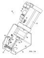
- FIG. 5 illustrates a particular embodiment of a precision spray pumping system used in connection with a spray skin treatment booth, such as a tanning booth.
- a spray skin treatment booth such as a tanning booth.
- four precision pump systems 40 are supported by a support structure 96. Each pump system 40 is in fluid communication with a respective reservoir 98.
- the precision pump system 40 is in electronic communication, through a controller, with a respective interrogator 100.
- the interrogator may read information stored on a machine readable tag, such as an RFID tag, attached to a removable container 102 of skin treatment solution, such as a sunless tanning solution.
- the information or data the interrogator 100 reads from the RFID tag may be used by the controller to direct operation of the pump system 40.
- the removable container 102 may contain any type of solution used in the application of a cosmetic to the skin in a spraying operation.
- the solution may be a solution for pre-tanning, moistening, tanning, and post-tanning.
- the solution may be clear or bronze and may be water or oil based.
- Each of the pump systems 40 may be plumbed to allow solution to be pumped from a respective reservoir 98 to the plurality of spray nozzles 16 (as shown in Figure 1 ). In this manner, each pump may be operable to pump a different solution to the spray nozzle 16.
- an individual may receive a spray skin treatment session, such as a spray tanning session that includes treatment from a plurality of different skin treatment solutions.
- the individual may receive a pre-tanning solution in a first treatment operation from a first reservoir pumped by a first pump system 40.
- the same person, in a second subsequent treatment operation may receive a bronzer skin treatment solution pumped by a second precision pump system 40 and sprayed on the individual.
- Each spray precision pump system 40 is operable as described herein to detect a predetermined position of its piston and communicate that information to a controller, which can then use that information in a comparison operation for fault detection to ensure optimum pump performance.
- a single positive displacement pump may siphon solution from a plurality of containers and/or reservoirs. Which solution is siphoned may be controlled by a solenoid or other type of valve.
- the pump phase may correspond to a delivery of a solution to one or more nozzles.
- the pump may be physically positioned near the nozzles to minimize the amount of solution that may remain in the liquid conduit lines after one solution is delivered and when switching to a second solution.
Abstract
Description
- This application claims priority to
U.S. Provisional Patent Application No. 61/702,185 filed on September 17, 2012 - The present invention relates generally to skin treatment spray systems, and more particularly to a precision pumping system for the delivery of skin treatment solutions in multiple spray treatment cycles.
- Booth spray systems for the application of skin lotions and cosmetics dispense a selectable variety of skin treatments including moisturizer and tanning treatments. Salon spray booths for sunless tanning and skin treatments offer multiple spray sessions with selections from a wide variety of skin lotions and tanning products. Many of the booth systems have moving gantries that apply the spray evenly over the full body or can be user-programmed to apply only to the face or legs. Some booths are outfitted with booth pre-heaters and full body drying systems. Automated booth spray systems used in salons consist basically of a booth structure that is either fully or partially enclosed with single or multiple spray nozzles positioned inside the booth. Reference is made to the following references generally directed to booth-type spray systems, the disclosures of which are hereby incorporated by reference:
U.S. Patent No. 6,199,557 to Laughlin filed on April 19, 1999 ;U.S. Patent No. 7,004,407 to Cooper filed on December 4, 2002 ;U.S. Patent No. 7,886,684 to Cooper et al. filed on April 28, 2006 ;U.S. Patent No. 8,201,288 to Thomason et al. filed on August 24, 2009 ;U.S. Patent Application Publication No. 2010/0266776 by Cooper et al. filed on April 20, 2010 ; andU.S. Patent Application Publication No. 2011/0133004 by Thomason et al. filed on October 22, 2010 . - The spray session is activated by the person receiving the spray treatment within the enclosure. An exhaust fan may be used to prevent overspray inside the booth or drifting spray escaping from the booth. Other booth features may include lights, voice prompts in different languages, heaters, skin drying systems, and interior washing and rinsing systems.
- The electrical and mechanical components in the rinse, drain, spray, gantry, heat and exhaust systems of these automated spray booths are operated in a sequence during a spray session by a microprocessor based or other sequential controller with a manual input device such as a keypad or button panel. Spray session parameters such as liquid flow, duration of spray, heater temperature, and the like are set and adjusted by input to the controller. Salon personnel and/or consumers using the spray system may manually enter certain operation parameters for each spray session.
- The spray solution used for sunless tanning is generally a water-based mixture of DHA (dihydroxyacetone) and/or erythrulose and various other skin care ingredients such as aloe vera. Often a cosmetic bronzer is added along with pleasant scents and other ingredients to enhance the tanning results and experience, such as formulations to balance skin pH. For best results, the spraying of the solution utilizes a finely atomized spray (mist), as opposed to using a spray stream or large spray droplets, because the mist of solution provides even coverage and reduces the risk of streaking or running of the spray deposit.
- The spray systems of these booth-type skin treatment sprayers generally include single or multiple containers or tanks containing liquid spray solution which is fed to the spray nozzles by single or multiple pumps or other methods, such as gravity or Venturi. Flow is generally controlled by solenoid valves and a mechanical pump for which flow rate can be varied by varying motor speed or pressure. Multiple nozzles may be stationary and positioned along the interior walls of the booth, or they may be mounted to a moving gantry. A spray system disclosed in
U.S. Patent No. 7,886,684 to Cooper et al. , the disclosure of which is hereby incorporated by reference, utilizes a single dose cartridge tank system. This system is configured with a single nozzle that oscillates while moving on a gantry. In addition, sprayers can be operated without a mechanical pump, relying on gravity or Venturi feed to the nozzle. - Multiple batch tank systems on skin care booth sprayers allow approximately 30 to more than 100 sessions between changing or re-filling the tanks. Booths with multiple tanks have the advantage of allowing a sequence of spray sessions with a choice of various lotions applied one after the other; for instance a moisturizer treatment may be applied after a tanning treatment, or a skin pH balancing spray may be applied before a tanning spray. Some booth models use refillable multiple tank systems with 2, 3 or 4 tanks. Many booth spray systems accommodate a more convenient bag-in-box system where multiple refillable and/or replaceable containers are received in a bay drawer of the unit as disclosed by
U.S. Patent No. 8,201,288 to Thomason et al. filed on August 24, 2009 , the disclosure of which is hereby incorporated by reference. - The liquid flow system of a booth-type spray system may clog resulting in less efficient pumping and possible under application of the skin treatment solution. Initially, the clog may not be significant enough to be immediately recognized. Thus, the spray system may continue to be operable but may provide incorrect flow rates and result in an inferior tanning experience. If the clog worsens, it may cause the pumping system to become inoperable and disable the spray booth during a spray tanning session of a paying customer.
- Embodiments disclosed herein propose a precision spray system for delivering a spray of skin treatment solution. The system includes at least one nozzle configured to emit a spray of skin treatment solution. A positive displacement pump is in fluid communication with the spray nozzle. The positive displacement pump includes a displaceable member, and displacement of the displaceable member corresponds to a pumping cycle of the positive displacement pump. A controller is in communication with the positive displacement pump. The controller is operable to apply a predetermined actuation parameter to direct an expected displacement and/or an expected displacement rate of the displaceable member and is also operable to receive an indication of an actual position of the displaceable member. The controller is further operable to compare the predetermined actuation parameter associated with the expected displacement of the displaceable member to a measured actuation parameter associated with the actual displacement of the displaceable member.
- In certain embodiments, based on the comparison, either the positive displacement pump continues to cycle and/or a fault condition is indicated. In certain embodiments, a fault condition may be a warning that the comparison has yielded a result that is out of a first tolerance, which may be associated with a first level caution. The system may indicate the caution condition and still continue the pumping operation.
- In certain embodiments, the positive displacement pump may be a piston-type pump that includes a stepper motor that functions as a linear actuator. The stepper motor linearly displaces the piston causing the pump to cycle. In this embodiment, the actuation parameter is associated with steps of the stepper motor. In an alternate embodiment, the actuation parameter may be electrical power applied to a non-stepper motor for a period of time, which may correspond to an actuation time. For example, electrical power may be applied to a D/C motor, an A/C motor, a speed controlled motor and the like.
- Technical advantages of the system and method for precisely controlling and validating movements of a pump for a skin treatment spray system include the ability to detect underperformance of the pump in either pumping or siphoning. An operator may be warned of the underperformance and may take corrective action at an appropriate time. In addition, the underperformance of the pump may be monitored to determine if the underperformance worsens, and if so, corrective action may be taken by the operator, at an appropriate time when the pump is not in use during a spray session.
- Further technical advantages include a pumping system that provides a steady, non-pulsed liquid flow for which the rate of flow and volume delivered may be precisely controlled and verified. Moreover, because solution is delivered in a single precisely controlled and maintained extension phase of the pump, calibration drift, that is common in conventional skin care treatment sprayer systems can be reduced or eliminated. In addition, because the pump system delivers liquid to a spray nozzle with minimum pre-pressurization time by extending a piston to pump the liquid, the pump system may reduce and/or eliminate problems associated with tolerance stack-up that occurs in conventional pumping systems.
- Still further technical advantages include the ability to track the actual amount of solution being dispensed by the spray nozzles, as opposed to only being able to track the desired amount of solution dispensed. In accurately tracking the actual dispensed amount, the remaining content of a removable and replaceable container may more accurately be determined.
- Other technical advantages will be readily apparent to one of ordinary skill in the art from the following figures, descriptions, and claims. Moreover, while specific advantages have been enumerated above, various embodiments may include all, some, or none of the enumerated advantages.
- A more complete understanding of the invention may be obtained by reference to the following drawings:
-
Figure 1 schematically illustrates a precision spray pumping system adaptable for spraying a skin treatment solution; -
Figure 2A is an isometric view of a precision piston-type pump system with a piston in a retracted position; -
Figure 2B is a cross sectional view of the precision piston-type pump system of -
Figure 2A ; -
Figure 3A is an isometric view of a precision piston-type pump system with a piston in an extended position; -
Figure 3B is a cross sectional view of the precision piston-type pump system of -
Figure 3A ; -
Figure 4 is a flow diagram of a method of operation for a precision spray pumping system; and -
Figure 5 is a portion of a spray tanning system employing a plurality of precision spray pumping systems according to embodiments of the present disclosure. -
Figure 1 is a schematic illustration of a precisionspray pumping system 10 according to embodiments of the present disclosure. Thesystem 10 includes apositive displacement pump 12 that is operable to draw a liquid from areservoir 14 and cause the liquid to be delivered to one ormore spray nozzles 16. In certain embodiments, thespray pumping system 10 may not include areservoir 14, and the pump will draw solution directly from a container, for example a removable container, of skin treatment solution. Any number of valves may be disposed among the fluid conduits connecting thereservoir 14, thepositive displacement pump 12, and thespray nozzles 16. Valves, such as check valves, control the fluid flow including the flow direction. - The
positive displacement pump 12 may be a piston pump powered by alinear actuator 18. Thelinear actuator 18 is in communication with acontroller 20. Thepositive displacement pump 12 also includes asensor system 22. Thesensor system 22 is also in communication with thecontroller 20 and may communicate a signal to thecontroller 20 when the sensor detects a flag that corresponds to a particular position of a piston of thepositive displacement pump 12. The detection of the flag corresponds to a home position of the piston. - The motor is actuated according to a predetermined actuation parameter that causes movement of the piston in the pump, which corresponds to delivery of a specific amount of liquid over a specific period of time. The actuation parameter may be any suitable control to cause movement of the piston by the linear actuator. For example, the actuation parameter may be applying power or a pulse or other motor activation method for a specified period of time to cause rotation of the rotor. In a preferred embodiment, the actuation parameter may be a pulse causing a rotor of a stepper motor to rotate a certain number of steps.
- In one embodiment, the
linear actuator 18 receives signals from thecontroller 20 and displaces the piston causing the liquid in thesystem 10 to be either siphoned or pumped. During a pump cycle thepump 12 receives a signal from thecontroller 20 that is intended to cause a predetermined expected distance of travel to extend the piston. A second signal is communicated from thecontroller 20 and directs the motor to reverse direction and retract the piston until an actual position of the flag, and thus the piston, is detected by thesensor 22. By comparing the steps taken by thelinear actuator 18 during the extension phase of the cycle to the steps taken by thelinear actuator 18 during the retraction (siphon) phase of the cycle, a determination may be made whether the piston traveled the expected distance in each phase of the cycle. If it is determined from the comparison that the piston did not travel an expected distance in one of the phases, and it is determined that the difference determined by the comparison is outside an acceptable tolerance, thesystem 10 provides an indication that a fault has occurred. The fault may indicate a blockage in the liquid conduit system that prevented the expected displacement of the piston in thepositive displacement pump 12. The difference in steps between each cycle phase is checked against a permissible variance or tolerance in determining whether to indicate a fault condition, and furthermore what fault condition to indicate. - The
reservoir 14 receives a liquid from acontainer 24. Any suitable number or type of valves may be disposed in the conduits between thereservoir 14 and thecontainer 24 to control the fluid flow. According to certain embodiments, thecontainer 24 is a removable bag-in-box container containing a skin treatment solution. The bag-in-box container 24 includes a tag 26 that is machine readable, such as a radio frequency identification (RFID) tag, bar code, QR (quick response) code, and the like. The tag 26 communicates information stored on or otherwise readable from the tag 26 to aninterrogator 28. - The
interrogator 28 is in communication with thecontroller 20 and receives information regarding thecontainer 24 and the solution therein and directs control of theprecision pumping system 10 based on that information. For example, theinterrogator 28 may receive information indicating that the solution within thecontainer 24 has a high viscosity. Thecontroller 20 uses this information to direct an appropriate displacement of the piston to pump a specific volume of the high viscosity solution. The proper displacement of the piston will cause an expected spray output from thespray nozzles 16. In this manner, aremovable container 24 of skin treatment solution is received by the precisionspray pumping system 10, and the solution may be sprayed through one or more of thenozzles 16 and applied to the skin of an individual in a skin treatment booth, such as a spray tanning booth. In addition, thecontroller 20 may also control agantry 30. Thegantry 30 supports and moves thespray nozzles 16. Thegantry 30 translates linearly to any position between an upper limit position and a lower limit position (and/or side-to side limits) to direct spray from thenozzles 16 to particular body parts of the person standing in the spray tanning booth. The control and movement of thegantry 30 is coordinated by thecontroller 20 such that a displacement of the piston in thepiston pump 12 correlates to a specific distance of travel of thegantry 30. For example, if thegantry 30 is to provide a skin treatment solution to just the legs of an individual standing in a spray tanning booth, a full displacement of the piston from a retracted position to an extended position is coordinated with the movement of thegantry 30 to pass over the legs of the individual. Thecontroller 20 also receives signals from aheight sensor 32 that optically or otherwise senses the height of an individual in the spray tanning booth and can adjust the travel of thegantry 30 accordingly. Other sensors, such as a linear or rotational encoder, or a time or limit switch corresponding to a particular position or motion of thegantry 30, may also be in communication with thecontroller 20 to provide information regarding the actual position of thegantry 30, which, similar to the piston position, may be compared to an expected position determined by thecontroller 20. - Operation of the
pump 12 generally corresponds with a spray treatment session. A spray treatment session may include one or more spray treatments, which may include one or more spray passes. Generally, a treatment may be associated with a specific solution and a pass may be associated with the gantry passing over a specific part of the customer's body and spraying skin treatment solution. For example, an individual may desire a spray treatment session to receive a spray tan. The customer may receive a first spray treatment of bronzer tanning solution delivered through the nozzles. The bronzer may be sprayed in a first pass, then the customer may be instructed to rotate 90 degrees to receive a second spray pass, then rotate 90 degrees to receive a third pass, then rotate 90 degrees to receive a fourth pass. After receiving the bronzer tanning solution, the customer may receive a moisturizer solution, which may include two spray passes over the entire body of the customer. Each spray pass may correspond to the customer rotating to receive the moisturizer on the front (facing the nozzles), then on the back of the customer. Finally, the customer may receive a second face treatment corresponding to a single pass of the nozzles over the face of the customer. - Between spray passes, the pump may retract to siphon additional liquid from the reservoir. This siphoning may correspond to a pause in the spray cycles. In certain embodiments, the siphoning corresponds to a dry pass of the gantry supporting the nozzles. Generally, no liquid is dispensed from the nozzles during a dry pass. The dry pass may or may not correspond to the system blowing air to dry the body. Thus, the operation of the pump is to extend the piston to spray solution, then to retract the piston to siphon liquid from the reservoir during a time when it is not necessary for the pump to spray. The time of each phase (pumping and siphoning) may be different and may be any suitable time desired for the spraying of skin treatment solution. For example, the pump may deliver a specific quantity of solution over a period of approximately 6.5 seconds. Then the siphoning phase may be quicker, such as three seconds. The siphoning phase may correspond to an instruction and delay for the customer to change their body position, which may be approximately twelve seconds. Or the siphoning time may be shorter and correspond to a dry pass of the gantry to prepare it for a subsequent spray pass over the customer. Siphoning occurs when the spray is not-desired and the pump is not spraying, such as a delay or a dry pass associated with a spray tanning operation. The
controller 20 includes one ormore processors 31 andmemory 35. Thus, the controller is essentially a microprocessor or other logic controller in communication with at least temporary memory and functions to control the components used in the spray session and to communicate data to other components of thesystem 10. In certain embodiments, thecontroller 20 may employ an Android or other suitable operating system, such as iOS. Thecontroller 20 may also be in communication with aninterface 36. Theinterface 36 may be integral with or remote to thecontroller 20. Theinterface 36 may be any suitable interface that allows a human to interact with and receive information from thecontroller 20. In certain embodiments, theinterface 36 may be a touch-screen, keypad, monitor, and the like. In a preferred embodiment, theinterface 36 may be a touch-screen that allows the user to communicate with thecontroller 20 by touching the screen where command icons and other information are displayed. Theinterface 36 may also be used to program thecontroller 20 or provide other information to thecontroller 20 that may be used to operate the precisionspray pumping system 10. -
Figures 2A and2B illustrate an isometric and a cross-sectional view, respectively, of an embodiment of a positive displacement pump as indicated inFigure 1 . The positive displacement pump is aprecision pump system 40, which ensures that a precise quantity of liquid is delivered to thespray nozzles 16. In certain embodiments, theprecision pump system 40 may pump approximately 25 ml over a time period of 4 to 25 seconds. In certain embodiments, theprecision pump system 40 may pump approximately 25 ml over approximately 6.5 seconds. This flow rate may correspond to a pass of thegantry 30 and thespray nozzles 16 over a portion of the body. For example, thegantry 30 may start at the head of a person and travel downward to the person's feet over a time of 6.5 seconds and simultaneously spray approximately 25 ml of spray tanning solution. The given values are only examples, and it should be understood that the system is operable to pump any suitable volume of solution over any suitable time. - A preferred embodiment of the present disclosure employs a piston-type pump which delivers a pulse-free spray, which is particularly applicable to spray tanning operations as discussed in
U.S. Patent No. 7,007,407 to Cooper , the disclosure of which is hereby incorporated by reference. Alternatively, the spray system of the present invention could use a multi-line peristaltic pump, a solenoid pump, a diaphragm pump, a reciprocating piston pump, a centrifugal pump, or vane pump, either alone or in combination with each other and/or the piston-type pump disclosed herein. - According to a certain embodiment, the
precision pump system 40 includes acylinder 42 and apiston 44. Thepiston 44 is a displaceable member that travels linearly within thecylinder 42 creating a pressure and volume differential, which siphons liquid from a reservoir and pumps it through the conduits to thespray nozzles 16 during a spray pumping cycle. The cycle includes a siphoning phase and a pumping phase. Thepiston 44 includes anupper seal 46 and alower seal 48. The upper seal andlower seal fluid chamber 50 within the cylinder is liquid-tight such that the liquid is prevented from escaping around thepiston 44. Theprecision pump system 40 may include only one seal; however multiple seals allows one to serve as a primary seal and another seal to server as a backup seal for improved reliability. - Displacement of the
piston 44 is directed by a suitable linear actuator. The linear actuator according to an embodiment of the present disclosure includes astepper drive motor 52. In certain embodiments, thestepper drive motor 52 causes alead screw 54 to be linearly displaced a certain distance based on signals received by themotor 52. The signals correspond to a known angular displacement of a rotor of themotor 52 and the corresponding displacement of arotor drive nut 55. Therotor drive nut 55 may be disposed within thecylinder 42 or outside of thecylinder 42. In the illustrated embodiment, therotor drive nut 55 is disposed within thecylinder 42 and analignment bushing 56 is disposed outside thecylinder 42. Thelead screw 54 extends through themotor 52. Therotor drive nut 55 meshes with corresponding threads of thelead screw 54 such that a specified rotation of therotor drive nut 55 by the rotor causes a corresponding linear displacement of thelead screw 54 and thepiston 44 attached to an end of thelead screw 54. In an alternate embodiment, therotor drive nut 55 may be disposed on an opposite side of themotor 52, for example, thealignment bushing 56 may be replaced by therotor drive nut 55. - As the
motor 52 of the linear actuator drives thepiston 44 from the extended position shown inFigures 3A and3B to the retracted position shown inFigures 2A and2B in the siphoning phase of the pump cycle, thefluid chamber 50 fills with solution from thesolution reservoir 14. In the illustrated embodiment, the retracted position corresponds to a maximum volume of thefluid chamber 50, and the extended position corresponds to a reduced volume of thefluid chamber 50 from the retracted position that occurs when the liquid is being pumped. The liquid is siphoned and pumped as thepiston 44 cycles between the retracted and extended position or any suitable intermediate positions as required by the desired fluid rate. The solution is drawn through aninlet 62 and through one ormore check valves 64. Thecheck valves 64 ensure that the liquid flowing through theinlet 62 into thefluid chamber 50 only flows in one direction because the pressure from the liquid flowing the opposite direction closes the valve and blocks liquid flow from such opposite direction. Thepiston 44 travels from the retracted position to the extended position and displaces the liquid in thefluid chamber 50 so that it exits theprecision pump system 40 through anoutlet 66. The liquid may travel through one or more check valves after it leaves theoutlet 66. The check valve on the outlet side of the liquid system performs similarly as thecheck valve 64 on the inlet side to ensure that liquid only travels one direction through the liquid system. Other types of direction control valves, such as solenoid valves, may be used to control of liquid through the system. Theoutlet 66 on the top of the pump facilitates dispelling unwanted air with minimal priming of the pump. - According to the teachings of the present disclosure, a piston-type pump as describe herein may reduce and/or eliminate the need for solenoid valves as a control for the delivery of the liquid to the spray nozzles. Thus, the piston pump reaches its pumping pressure quickly and solution can be delivered virtually simultaneously with the displacement of the pump. Also, the solution may cease being delivered virtually simultaneously with the ceasing of the extension of the piston.
- Attached at an opposite end of the
lead screw 54 from thepiston 44 is aflag 57. Theflag 57 is a component of theposition sensor system 22, as shown and described with respect toFigure 1 . Because theflag 57 is attached to thelead screw 54, it is linearly displaced the same distance as thepiston 44 when thelinear actuator 52 is operated to siphon or pump liquid to one ormore spray nozzles 16 according to the teachings of the present disclosure. In one embodiment, motion of theflag 57 and thus the lead screw and thepiston 44 is constrained by aslot 68. In addition, the coupling of theslot 68 and theflag 57 prevent thelead screw 54 from turning and also prevent thepiston 44 from rotating. Theflag 57 also serves as a visual indicator of the displacement of thepiston 44 within thecylinder 42. - The
slot 68 is formed in a panel of a mountingbracket 70. The mountingbracket 70 is a metal or plastic bracket with features to attach theprecision pump system 40 to a drawer of a spray tanning booth as shown inFigure 5 . In certain embodiments, the mountingbracket 70 may be an angled mounting bracket which holds the precision pump system at a predetermined angle. - As shown in
Figures 2A and2B , when thepiston 44 is in a retracted position, theflag 57 displaces anarm 58 of asensor 60. Displacement of thearm 58 creates an electrical contact with thesensor 60. The electrical contact is communicated to thecontroller 20, which determines that thepiston 44 is in a known retracted or home position as shown inFigures 2A and2B . -
Figures 3A and3B show isometric and cross section views, respectively, of theprecision pump system 40 in a piston extended position. Theprecision pump system 40 has this orientation once the pump has completed the pumping phase of its cycle and the liquid has been directed from thefluid chamber 50 through the conduit and to thespray nozzles 16. As shown inFigures 3A and3B , theflag 57 is displaced away from thesensor 60, and thus thearm 58 is not displaced by theflag 57. In the next phase of the cycle, where thepiston 44 retracts, theflag 57 displaces thearm 58, thus the position of theflag 57 and thepiston 44 is sensed, and electronically communicated to thecontroller 20 such that the controller determines that the piston is in its known fully retracted position. In other embodiments, other types of proximity sensing means may be used. For example, the sensor may be a mechanical limit switch as shown, or may be a magnetic device or any other device for sensing the position and proximity of a mechanical component, such as a pump piston. - As explained in more detail below with respect to
Figure 4 , the number of motor steps to move thepiston 44 to the known retracted position may be compared with the number of motor steps that previously moved thepiston 44 to an expected extended position, and a determination of whether a fault has occurred may be made based on that comparison. According to an alternate embodiment, the position sensor may be configured such that the extension of the piston, as opposed to the retraction of the piston, is detected by the sensor and considered the home position. - In the case of the stepper motor illustrated, the motor may be configured to slip. That is the rotor may be directed to turn in response to a received pulse, but the piston will not displace. Thus, an incomplete blockage in the liquid line may result in an initial displacement of the piston, and then the
motor 52, or a part of the piston drive system, may slip, skip, or stall as thepiston 44 is opposed by the increased pressure created by the blockage. In the subsequent pump phase, the motor steps to retract thepiston 44 until theflag 57 is detected by thesensor 60 at the fully retracted home position are determined. Thus, the number of motor steps intended to be taken by the motor to extend the piston a known distance to deliver a particular quantity of skin treatment solution can be compared to the number of motor steps actually taken to return thepiston 44 to the home position where theflag 57 is detected. From this comparison, the steps taken by the motor in the extension phase that did not result in a displacement of the piston may be determined, which provides an indication of the severity of the blockage. In other embodiments, the motor may be configured to stall or slow down when the piston is opposed by a predetermined force. In still alternate embodiments, a clutch mechanism may be employed to allow the motor to rotate without displacing the piston when the piston is opposed by a predetermined force in the fluid line. -
Figure 4 is a flow diagram of amethod 78 of operation of the precision spray pumping system according to an embodiment of the present disclosure. Themethod 78 begins atstep 79 where session input is received by the controller. A user may build a skin treatment session by inputting certain desired spray treatments, certain levels of treatment corresponding to an amount of skin treatment solution to be sprayed by the system, and a particular part of the body or the whole body over which the gantry will travel as the skin treatment solution is sprayed. The user may provide such input for multiple treatments to be provided by the sprayer during a session. - At
step 80, the controller determines the number of spray passes to perform and the amount of solution to deliver during a spray pass. This determination is based on the session input provided by the user. Generally, a spray pass corresponds to a single extension of the pump, which delivers the skin treatment solution to the nozzles and is sprayed onto the person in the skin treatment booth as the gantry moves to allow the spray from the nozzles to coat a particular part of the body. The single extension of the pump allows a non-pulsed spray to be delivered over a certain time period, such as 6.5 seconds. This non-pulsed spraying of the skin treatment solution is referred to as a spray pass. A treatment with a skin treatment solution typically includes multiple spray passes over a designated part of the body. For example, the user receives one spray pass of a sunless tanning solution over the front of her whole body. Then, as part of the same treatment, the user is instructed to turn 90 degrees and receive another spray pass of the sunless tanning solution over the side of her body. Thus, the controller receives the input regarding the desired treatments and determines the number and the sequence of spray passes to perform. - At
step 81, the piston is confirmed to be in its retracted, home position. As previously described, the retracted position of the piston activates a sensor, which communicates to the controller that the piston is in the home position. If the piston is not in its home position, it is retracted and the cylinder of the pump is filled with skin treatment solution and until the flag is detected and the piston is confirmed to be in its known, home position. From the known, home position, information about the travel of the piston during the extension and subsequent retraction phases of the pump cycle can be determined and compared. If the home position is not reached after a predetermined period of time or after a predetermined number of attempts, the controller may indicate an error condition. - The system starts the session according to the input of the user, at
step 82. The user may initiate the session after entering the skin treatment spray booth and touching a touch-sensitive sensor to provide input to the controller that the user is in position and ready to receive the spray session. - At
step 84, the motor is actuated according to a predetermined actuation parameter intended to extend thepiston 44 and pump a specific amount of liquid over a specific period of time or a specific movement distance of thepiston 44, which corresponds to a spray pass of the gantry over a part or the whole body. Precise and consistent application of a skin treatment solution is achieved according to the teachings of the present disclosure. For example, a precise and consistent volume of skin treatment solution is dispensed by the pumping system. By confirming the extension and retraction phases of a pump are equal within a certain acceptable tolerance, less than 5% volume variation in spray passes may be achieved. In certain embodiments, the volume variation in spray passes is less than 1%. - The session input determines the magnitude of the actuation parameter, which may be any suitable control to cause movement of the
piston 44. For example, the actuation parameter may be applying power or a pulse or other motor activation method for a specified period of time to cause rotation of the rotor. In a preferred embodiment, the actuation parameter may be causing a rotor of a stepper motor to rotate a certain number of steps. Actuation of the motor using the predetermined actuation parameter causes displacement of the piston, which should be a desired displacement to extend thepiston 44. The predetermined number of steps (or time, etc.) causes an expected angular displacement of a rotor within the motor, which corresponds to an expected displacement distance of thepiston 44 during a pumping phase of the pump's cycle. However, if there is a force greater than a predetermined value, the motor or other drive system will slip or stall and the intended displacement of thepiston 44 will not correspond to the actual displacement of thepiston 44. - At
step 86, the motor is actuated in steps (or time or otherwise) to retract the piston and draw skin treatment solution into the pump in connection with a second (siphoning) phase of the pump's cycle. The piston is retracted while another action is occurring. For example, the piston may retract while the gantry moves to be in position for another spray pass. Or, the piston may retract during a time period in which the user is given a short amount of time to rotate to be in position to receive another spray pass over the side of her body. - The piston is retracted until the sensor is activated at
step 88. As described herein, activating the sensor includes displacement of an arm to create an electrical connection, which is communicated to thecontroller 20. - At
step 90, the controller determines if the extension pump phase is approximately equal to the retraction pump phase. For example, it is determined whether the predetermined actuation parameter, for example the number of steps (or distance or time) associated with retracting the piston is approximately equal to the predetermined number of steps (or time, etc.) used to extend the piston. In normal operation, the predetermined actuation parameter needed to retract the piston to activate the sensor should be approximately equal to the predetermined actuation parameter used to extend the piston, as described with respect to step 84. The number of steps for retraction may be within an acceptable range, tolerance, or variance but may not be exactly equal to the predetermined number of steps to extend the piston and the controller may determine that the retraction steps are approximately equal to the extension steps. In certain embodiments, the actuation parameter may be associated with rotation or linear movement of an encoder. The actuation parameter may also be steps of a stepper motor or electrical motor power applied over a period of time to an AC or DC motor, which may or may not have speed control. - If it is determined that the retraction actuation parameter is approximately equal (within an acceptable tolerance) to the extension actuation parameter, the pump will continue to cycle and the method returns to step 84, and the system is prepared to deliver skin treatment solution for another spray pass. If it is determined that the actuation parameter to retract the piston is not equal (within an acceptable tolerance) to the actuation parameter used to extend the piston, then a fault level may be determined and indicated at
step 92. The system may take any suitable controller and/or mechanical action in response to a particular fault level determination including, but not limited to, continue pumping, ceasing pumping, and/or sending a communication notifying a service technician of the fault. - The fault level may be a first caution level, a second caution level, or a severe fault level, which may correspond to one or two yellow LED indicators and/or a red LED indicator. In other embodiments, the fault level may be displayed by the interface. As an example, the expected extension of the piston may have been intended to cause the delivery of 20 ml of solution to the nozzles. After retracting the piston and making the comparison, it may be determined that the piston only extended a distance sufficient to
delivery 18 ml of solution, each step of the motor corresponds to the delivery of a fraction of a milliliter of solution. The difference of 2 ml may be sufficient to provide a first caution indicator but allow the pump to continue operation to avoid inconveniencing the customer during the middle of a spray tanning session. However, if the pump actually only delivered 10 ml of solution, this may correspond to a severe fault warranting shut down of the pump from continued operation. - By tracking multiple caution levels, it may be determined if the malfunction in delivery continues to worsen, which may be an indicator of a clog in the liquid lines, a malfunctioning valve, or may be an indication of a malfunctioning pump. In addition, the controller may communicate the fault indicator to a service technician via email or other electronic communication method.
- If the number of steps used to retract the position to activate the sensor is less than the predetermined number of steps used to extend the piston, it may be determined that a blockage in the liquid system prevented the piston from fully extending. Thus, it may be determined that there is a clog in the liquid system upstream of the pump.
- If the number of steps to retract the piston is greater than the number of steps to extend the piston, it may be determined that more steps and motor power was required to retract the piston to activate the sensor than was expected. In this instance, it may be determined that the pump system has erred in its siphoning phase. Accordingly, this fault condition may likewise be indicated by the controller. The method ends after either a fault or a caution level is indicated and/or a go condition is determined and the pump continues to cycle. Of course, the method also ends upon the successful and/or fault-free completion of the predetermined number of pump cycles as determined by the spray treatment session being delivered. The comparison operation is employed during each pumping cycle, which allows precise delivery of a specific amount of skin treatment solution during each spray pass. Also, the
precision pump method 78 may be initiated by an operator in a single instance to assist in diagnosis of a possibly malfunctioning system. In addition, the system may indicate that the piston did not return home if the sensor is not activated within a predetermined time limit. - Thus, the precision pump system according to embodiments of the present disclosure delivers consistent sprayed solution from the nozzles. When spray tanning solution, such as a bronzer, is sprayed from the nozzles, the user receives repeatable and consistent results in darkness/color level for each spray pass, for each spray treatment, and for each spray session.
- Consistent with the teachings of the present disclosure, other sensing systems then that described herein may be used to detect a position of the piston. For example, the position of the piston may be determined using a linear or rotational encoder. In an alternative embodiment, the position of the piston may be determined by a timer.
Figure 5 illustrates a particular embodiment of a precision spray pumping system used in connection with a spray skin treatment booth, such as a tanning booth. As shown, fourprecision pump systems 40 are supported by asupport structure 96. Eachpump system 40 is in fluid communication with arespective reservoir 98. In addition, theprecision pump system 40 is in electronic communication, through a controller, with arespective interrogator 100. The interrogator may read information stored on a machine readable tag, such as an RFID tag, attached to aremovable container 102 of skin treatment solution, such as a sunless tanning solution. The information or data theinterrogator 100 reads from the RFID tag may be used by the controller to direct operation of thepump system 40. Theremovable container 102 may contain any type of solution used in the application of a cosmetic to the skin in a spraying operation. For example, the solution may be a solution for pre-tanning, moistening, tanning, and post-tanning. The solution may be clear or bronze and may be water or oil based. - Each of the
pump systems 40 may be plumbed to allow solution to be pumped from arespective reservoir 98 to the plurality of spray nozzles 16 (as shown inFigure 1 ). In this manner, each pump may be operable to pump a different solution to thespray nozzle 16. Thus, an individual may receive a spray skin treatment session, such as a spray tanning session that includes treatment from a plurality of different skin treatment solutions. For example, the individual may receive a pre-tanning solution in a first treatment operation from a first reservoir pumped by afirst pump system 40. The same person, in a second subsequent treatment operation, may receive a bronzer skin treatment solution pumped by a secondprecision pump system 40 and sprayed on the individual. Each sprayprecision pump system 40 is operable as described herein to detect a predetermined position of its piston and communicate that information to a controller, which can then use that information in a comparison operation for fault detection to ensure optimum pump performance. - According to an alternate embodiment, a single positive displacement pump according to the teachings of the present disclosure may siphon solution from a plurality of containers and/or reservoirs. Which solution is siphoned may be controlled by a solenoid or other type of valve. The pump phase may correspond to a delivery of a solution to one or more nozzles. In this embodiment, the pump may be physically positioned near the nozzles to minimize the amount of solution that may remain in the liquid conduit lines after one solution is delivered and when switching to a second solution.
Claims (15)
- A precision pumping system for delivering a spray of skin treatment solution, comprising:at least one nozzle configured to emit a spray of a skin treatment solution;a positive displacement pump in fluid communication with the at least one spray nozzle, the positive displacement pump comprising a displaceable member,displacement of the displaceable member corresponding to a pumping cycle of the positive displacement pump;a controller in communication with the positive displacement pump, the controller being operable to apply a predetermined actuation parameter to direct an expected displacement of the displaceable member and being further operable to receive an indication of an actual position of the displaceable member; andwherein the controller is further operable to compare the predetermined actuation parameter associated with the expected displacement of the displaceable member to a measured actuation parameter associated with the actual displacement of the displaceable member.
- The system of claim 1, wherein the predetermined actuation parameter is associated with steps of a stepper motor; or
wherein the predetermined actuation parameter is associated with electrical power applied for a period of time to a linear actuator. - The system of claim 2, wherein the linear actuator comprises a motor.
- The system of claim 1 or 2, wherein the positive displacement pump comprises a piston pump and the displaceable member comprises a piston.
- The system of claim 4, further comprising:a linear actuator operable to displace the piston; ora linear actuator operable to direct motion of a lead screw, the lead screw having a piston coupled to a first end and a flag coupled to an opposite end, the detection of the flag corresponding to the actual position of the displaceable member.
- The system of claim 5, wherein the linear actuator comprises a motor.
- The system of claim 6, wherein the motor comprises a stepper motor.
- The system of claim 5, further comprising a mounting bracket defining a guide slot constraining a linear motion of the flag.
- The system according to any one of the preceding claims, further comprising:a flag coupled to the displaceable member; anda position sensor operable to detect the flag.
- The system of claim 9, wherein the position sensor comprises an arm and displacement of the arm by the flag generates an electrical signal associated with the actual position of the displaceable member.
- The system according to any one of the preceding claims, wherein the positive displacement pump delivers the skin treatment solution to the at least one spray nozzle.
- A system for spraying a skin treatment solution, according to any one of the claims 1 to 11, comprising:a controller operable to control a plurality of precision pumping systems;at least one spray nozzle fluidly coupled to the plurality of precision pumping systems, a precision pumping system comprising:a positive displacement pump in fluid communication with the at least one spray nozzle, the positive displacement pump comprising a displaceable member,displacement of the displaceable member corresponding to a pumping cycle of the positive displacement pump;the positive displacement pump in communication with the controller, the controller being operable to apply a predetermined actuation parameter to direct an expected displacement of the displaceable member and being further operable to receive an indication of an actual position of the displaceable member; andwherein the controller is further operable to compare the predetermined actuation parameter associated with the expected displacement of the displaceable member to a measured actuation parameter associated with the actual displacement of the displaceable member.
- A precision sprayer system for spraying a skin treatment solution, according to any one of the preceding claims, comprising:a piston pump comprising a piston and a linear actuator, the linear actuator operable to displace the piston during a pumping cycle of the piston pump;a position sensor operable to detect a flag coupled to the piston, detection of the flag corresponding to a known position of the piston;a controller in communication with the linear actuator, the controller being operable to apply an actuation parameter to direct a displacement of the piston andbeing further operable to receive a signal from the position sensor upon detection of the flag;at least one sprayer nozzle receiving a skin treatment solution from the piston pump; andwherein the controller is further operable to compare a predetermined actuation parameter associated with an expected displacement of the piston to a measured actuation parameter associated with an actual position of the piston.
- The system of claim 13, wherein the linear actuator comprises a motor and the actuation parameter is associated with a current for a period of time received by motor.
- The system of claim 13 or 14, wherein the position sensor comprises an arm and displacement of the arm by the flag generates an electrical signal associated with the actual position of the piston.
Applications Claiming Priority (1)
| Application Number | Priority Date | Filing Date | Title |
|---|---|---|---|
| US201261702185P | 2012-09-17 | 2012-09-17 |
Publications (2)
| Publication Number | Publication Date |
|---|---|
| EP2708288A2 true EP2708288A2 (en) | 2014-03-19 |
| EP2708288A3 EP2708288A3 (en) | 2015-05-06 |
Family
ID=49237021
Family Applications (1)
| Application Number | Title | Priority Date | Filing Date |
|---|---|---|---|
| EP20130184687 Withdrawn EP2708288A3 (en) | 2012-09-17 | 2013-09-17 | Precision pumping system for spray treatment cycles |
Country Status (3)
| Country | Link |
|---|---|
| US (1) | US9278367B2 (en) |
| EP (1) | EP2708288A3 (en) |
| CA (1) | CA2827099A1 (en) |
Cited By (1)
| Publication number | Priority date | Publication date | Assignee | Title |
|---|---|---|---|---|
| EP3169901A4 (en) * | 2014-07-14 | 2018-03-14 | Graco Minnesota Inc. | Material dispense tracking and control |
Families Citing this family (12)
| Publication number | Priority date | Publication date | Assignee | Title |
|---|---|---|---|---|
| US9032565B2 (en) | 2009-12-16 | 2015-05-19 | Kohler Co. | Touchless faucet assembly and method of operation |
| CN103939878B (en) * | 2014-04-22 | 2016-02-17 | 崔哲 | Steam beauty treatment hair care machine |
| US10155208B2 (en) * | 2014-09-30 | 2018-12-18 | Taiwan Semiconductor Manufacturing Co., Ltd. | Liquid mixing system for semiconductor fabrication |
| US20160330901A1 (en) * | 2015-05-14 | 2016-11-17 | Deere & Company | Product distribution device with section control monitoring |
| CN204742996U (en) * | 2015-07-13 | 2015-11-11 | 温州芒果电器制造有限公司 | Large capacity hair care essential oil tuyere |
| CN109195646B (en) * | 2016-06-01 | 2023-04-25 | 费森尤斯维尔公司 | Infusion device and method allowing detection of drift of sensor signal |
| US11465165B2 (en) * | 2017-08-26 | 2022-10-11 | The Boeing Company | High-volume low-pressure end effector |
| US11772234B2 (en) | 2019-10-25 | 2023-10-03 | Applied Materials, Inc. | Small batch polishing fluid delivery for CMP |
| CN112605163B (en) * | 2020-12-04 | 2022-12-30 | 江永县青鹤铝业有限公司 | Interrupted feed structure and orthopedic paint spraying apparatus of aluminum alloy plate |
| CN113953105A (en) * | 2021-11-22 | 2022-01-21 | 王彦军 | Centrifugal coating paint spraying device |
| CN115106216B (en) * | 2022-07-18 | 2023-08-18 | 南京工业大学 | Spraying device |
| CN115591698A (en) * | 2022-10-31 | 2023-01-13 | 重庆长安汽车股份有限公司(Cn) | Intelligent vehicle body release control method and system based on double lines of automobile coating production |
Citations (6)
| Publication number | Priority date | Publication date | Assignee | Title |
|---|---|---|---|---|
| US6199557B1 (en) | 1997-10-08 | 2001-03-13 | Laughlin Products, Inc. | Method of and apparatus for automatically coating the human body |
| US7004407B2 (en) | 2001-12-04 | 2006-02-28 | Mystic Tan, Inc. | Uniform metering system for spray applications |
| US20100266776A1 (en) | 2009-04-21 | 2010-10-21 | Mt Industries, Inc. | Automated skin spray and dry system |
| US7886684B2 (en) | 2003-05-09 | 2011-02-15 | Mt Industries, Inc. | Gantry tower spraying system with cartridge/receptacle assembly |
| US20110133004A1 (en) | 2009-12-04 | 2011-06-09 | Mt Industries, Inc. | Skin treatment spray nozzle system for automatic spray gantry |
| US8201288B2 (en) | 2006-01-05 | 2012-06-19 | Sunless, Inc. | Automatic body spray system |
Family Cites Families (118)
| Publication number | Priority date | Publication date | Assignee | Title |
|---|---|---|---|---|
| US1586009A (en) | 1923-02-08 | 1926-05-25 | Shelburne Augustine | Air brush |
| US1982509A (en) | 1931-01-10 | 1934-11-27 | Frank Paul | Apparatus for applying treatment media to the living body |
| US2139133A (en) | 1936-09-28 | 1938-12-06 | Jens A Paasche | Airbrush |
| BE439965A (en) | 1939-12-06 | 1900-01-01 | ||
| US2267264A (en) | 1940-05-14 | 1941-12-23 | James G Bland | Air conduit heater |
| US2401504A (en) | 1943-12-04 | 1946-06-04 | Jens A Paasche | Airbrush device |
| US3057558A (en) | 1958-02-19 | 1962-10-09 | Schweitzer Electrostatic Compa | Electrostatic atomizing head |
| US3007178A (en) | 1958-07-07 | 1961-11-07 | Altman Murray | Combination steam bath and shower |
| US3344992A (en) | 1964-01-27 | 1967-10-03 | Edward O Norris | Spray gun |
| US3437791A (en) | 1965-10-21 | 1969-04-08 | Charles S Gardner | Electrical heating attachment for aerosol cans |
| US3587118A (en) | 1968-05-22 | 1971-06-28 | John R Compton | Sit-in shower and bath tub,both with driers |
| US3596834A (en) | 1969-07-28 | 1971-08-03 | Gen Electric | Self-reversing spray arm assembly for a washing appliance |
| US3662407A (en) | 1970-05-25 | 1972-05-16 | Donald E Colucci | Personal hygiene device |
| US3759449A (en) | 1971-03-04 | 1973-09-18 | Ruthman Machinery Co | Device for producing coolant mist |
| US3721250A (en) | 1971-04-16 | 1973-03-20 | Clairol Inc | Mist applicator comb |
| US3770201A (en) | 1972-05-25 | 1973-11-06 | R Sanders | Air heating device for artists air brush |
| US3780943A (en) | 1972-08-14 | 1973-12-25 | D Lilja | Spray apparatus and method |
| US3854489A (en) | 1972-10-12 | 1974-12-17 | Schick Inc | Hair styling appliance |
| JPS5428783B2 (en) | 1974-02-14 | 1979-09-19 | ||
| US3905379A (en) | 1974-01-14 | 1975-09-16 | Sunbeam Corp | Hair dryer with mist feature |
| LU70281A1 (en) | 1974-06-10 | 1976-04-13 | ||
| US3989143A (en) | 1974-07-15 | 1976-11-02 | Nalco Chemical Company | Upper strata chlorination of upper sections of clarifiers |
| FR2341323A1 (en) | 1976-02-19 | 1977-09-16 | Villard Pierre | APPARATUS FOR SPREADING PARAFFIN ON THE HUMAN BODY FOR SLIMMING TREATMENTS |
| US4056078A (en) | 1976-08-03 | 1977-11-01 | Clem Blafford | Automatic dog washer |
| US4130120A (en) | 1977-04-11 | 1978-12-19 | Kohler Co. | Bathing chamber |
| US4114022A (en) | 1977-08-16 | 1978-09-12 | Braulke Iii Herbert A | Combined hot air and steam hair dryer |
| GB2056852B (en) | 1979-07-25 | 1984-06-20 | Matsushita Electric Works Ltd | Facial sauna device |
| US4394967A (en) | 1979-12-18 | 1983-07-26 | Jean Amiaut | Gun for applying paints by hot process |
| US4382424A (en) | 1981-11-27 | 1983-05-10 | Hogar S.R.L. | Automatic apparatus for cleaning dogs and similar animals |
| US4386739A (en) | 1981-12-18 | 1983-06-07 | Graco Inc. | Nozzle for hydrostatic fluid tip |
| IT8254051V0 (en) | 1982-12-10 | 1982-12-10 | Mario Altissimo | AUTOMATIC APPARATUS FOR WASHING DOGS AND SIMILAR ANIMALS |
| US4523080A (en) | 1983-03-14 | 1985-06-11 | Bolton John D | Apparatus for treatment of hair and scalp |
| IT8353345V0 (en) | 1983-05-20 | 1983-05-20 | Rolando Walter | AUTOMATIC APPARATUS FOR WASHING THE FEET |
| US5038769A (en) | 1983-06-29 | 1991-08-13 | Krauser Robert S | Method and apparatus for treating ailments |
| US4605019A (en) | 1984-09-05 | 1986-08-12 | Sorenco, Inc. | Sprayer attachment for a hair dryer |
| US4597757A (en) | 1985-07-22 | 1986-07-01 | Ruderian Max J | Heat and salve applicator |
| JPS6272834A (en) | 1985-09-24 | 1987-04-03 | アイシン精機株式会社 | Privates washing apparatus |
| DE3540990A1 (en) | 1985-11-19 | 1987-05-21 | Heinrich Koller | Hot-air blower with a spray device for liquid |
| US4714462A (en) * | 1986-02-03 | 1987-12-22 | Intermedics Infusaid, Inc. | Positive pressure programmable infusion pump |
| DE3631270A1 (en) | 1986-09-13 | 1988-03-24 | Kopperschmidt Mueller & Co | DEVICE FOR SPRAY COATING WORKPIECES |
| DE3720938A1 (en) | 1987-06-25 | 1989-01-05 | Peter Fuchs | Device for spraying liquids by means of propellent gas |
| US4915303A (en) | 1987-09-28 | 1990-04-10 | Accuspray, Inc. | Paint spray gun |
| US4862754A (en) * | 1987-12-11 | 1989-09-05 | Precision General, Inc. | Portable piston style sample cylinder |
| GB8802130D0 (en) | 1988-02-01 | 1988-03-02 | Devilbiss Co | Spraygun |
| US4901379A (en) | 1988-04-25 | 1990-02-20 | Hydrabaths, Inc. | Air excitation hydromassage system |
| US4941808A (en) * | 1988-06-29 | 1990-07-17 | Humayun Qureshi | Multi-mode differential fluid displacement pump |
| CA1336373C (en) | 1988-09-21 | 1995-07-25 | Nordson Corporation | Apparatus for spraying hot melt adhesives |
| US5078322A (en) | 1988-10-24 | 1992-01-07 | Wagner Spray Tech Corporation | Low pressure high volume spray gun |
| DE8911932U1 (en) | 1989-10-06 | 1990-01-18 | Bersch & Fratscher Gmbh, 8757 Karlstein, De | |
| US5074322A (en) | 1990-12-06 | 1991-12-24 | Jaw Chin Woei | Structure of sterilizing hand dryer |
| US5136735A (en) | 1991-03-07 | 1992-08-11 | Zimmerman Phyllis E | Immobile patient shower and skin care unit |
| US5228150A (en) | 1991-12-13 | 1993-07-20 | Parker Milton B | Patient bathing apparatus |
| US5339540A (en) | 1992-07-21 | 1994-08-23 | Syd Edwards | Hair dryer accessory device |
| US5261427A (en) | 1992-08-04 | 1993-11-16 | Moshe Dolev | Comb device for destruction of lice and lice eggs |
| US5241974A (en) | 1992-11-25 | 1993-09-07 | Ta-Wei Chen | Hair appliance for directing warm air to hair |
| NO177453C (en) | 1992-11-30 | 1995-09-20 | Trosterud Mek Verksted As | Tripod and foot treatment facility |
| US5664593A (en) | 1993-12-06 | 1997-09-09 | Mcclain; Edward T. | Apparatus for applying suntanning lotion mist |
| US5387200A (en) | 1994-01-10 | 1995-02-07 | Sun-Safe Technologies Limited Partnership | Portable applicator for applying skin protection fluids |
| US5520519A (en) | 1994-09-09 | 1996-05-28 | Seiko Epson Corporation | Performance enhancing base for small compressor |
| ZA959368B (en) | 1994-11-04 | 1996-01-01 | Croda Inc | Fatty alcohol phosphate ester emulsifier compositions |
| US5558276A (en) | 1994-12-14 | 1996-09-24 | Tram-7 Precision, Inc. | Air gun for spraying and drying air-dryable liquid materials |
| US5642570A (en) | 1996-04-09 | 1997-07-01 | Lee; Tzung Sheng | Structure of hair drier |
| IT1289114B1 (en) | 1996-06-12 | 1998-09-25 | N T S Nuove Tecnologie Sanitar | AUTOMATIC PLANT FOR HYGIENIC CLEANING AFTER PHYSIOLOGICAL FUNCTIONS |
| US5738728A (en) * | 1996-07-26 | 1998-04-14 | Bio Dot, Inc. | Precision metered aerosol dispensing apparatus |
| US7041089B2 (en) | 1997-10-08 | 2006-05-09 | Laughlin Products, Inc. | Automated system for coating the human body: virtual motion |
| US6431180B2 (en) | 1997-10-08 | 2002-08-13 | Laughlin Products, Inc. | Automated system for coating the human body |
| US6416747B1 (en) | 1997-10-08 | 2002-07-09 | Laughlin Products, Inc. | Method, apparatus, and composition for automatically coating the human body with plural components |
| US5991937A (en) | 1998-03-10 | 1999-11-30 | Safara; Stephen G | Bidet device |
| US5971298A (en) | 1998-05-04 | 1999-10-26 | Northrop Grumman Corporation | Micro spray gun |
| US6106547A (en) | 1998-09-22 | 2000-08-22 | Huei-Jung; Lien | Hot/cold dual-mold skin treatment apparatus |
| JP2000135111A (en) | 1998-10-30 | 2000-05-16 | Koichiro Takana | Dryer |
| WO2000054892A1 (en) | 1999-03-12 | 2000-09-21 | Troy Howard Cooper | Misting apparatus for application of coating materials to skin surface |
| US6418573B1 (en) | 1999-08-12 | 2002-07-16 | Masatoshi Masuda | Bathing method and bathing apparatus |
| AU2001249510A1 (en) | 2000-03-27 | 2001-10-08 | Schott Glas | New cosmetic, personal care, cleaning agent, and nutritional supplement compositions comprising bioactive glass and methods of making and using the same |
| US6802830B1 (en) | 2000-06-16 | 2004-10-12 | Drew Waters | Device and method that generates a fog capable of altering the color of human skin |
| US6302122B1 (en) | 2000-09-22 | 2001-10-16 | Spectrum Products, Inc. | Apparatus for automatic application of compositions to the skin |
| US6673097B1 (en) | 2001-02-23 | 2004-01-06 | Hollywood Tanning Systems, Inc. | Tanning booth having reduced tanning time |
| AU2002355429A1 (en) | 2001-08-08 | 2003-02-24 | Spectrum Products, Inc. | Apparatus for automatic application of sunless tanning composition having an attached dressing room |
| JP2003159305A (en) | 2001-09-13 | 2003-06-03 | Matsushita Electric Works Ltd | Skin care device |
| EP1438158B1 (en) | 2001-09-21 | 2007-03-21 | Extrude Hone Corporation | Abrasive flow machining apparatus and method |
| US7083115B2 (en) | 2001-10-04 | 2006-08-01 | Spraying Systems Co. | Spray gun with removable heat jacket |
| US6554208B1 (en) | 2001-11-21 | 2003-04-29 | Hollywood Tanning Systems, Inc. | Tanning booth having automated spray |
| JP4087796B2 (en) | 2002-03-22 | 2008-05-21 | アンヘル セグラ ムーニョス | Animal conditioning, cleaning, disinfection, parasite removal, hydromassage equipment |
| US7004932B2 (en) | 2003-01-24 | 2006-02-28 | Lester Szurko | Overspray collection booth |
| CA2515301C (en) | 2003-02-07 | 2013-05-07 | Warrick J. Smith | Tanning booth |
| US20040156793A1 (en) | 2003-02-11 | 2004-08-12 | Golden Chiropractic Group Ltd. | Skin care composition and method of skin treatment |
| WO2004084983A1 (en) | 2003-03-21 | 2004-10-07 | Paul Spivak | Spray booth method and apparatus |
| US7297211B2 (en) | 2003-05-09 | 2007-11-20 | Mystic Tan, Inc. | Single-dose spray system for application of liquids onto the human body |
| US20040228810A1 (en) | 2003-05-13 | 2004-11-18 | Starr Hamson | Sprayable sunless tanning solution with sunscreen protection |
| US6913572B2 (en) | 2003-09-17 | 2005-07-05 | Allen Licht | Spa capsule |
| SE526593C2 (en) | 2003-10-21 | 2005-10-11 | Scandfilter Ab | Air filtration systems |
| US20060275555A1 (en) | 2004-02-10 | 2006-12-07 | Daniele Colizza | Painting method and apparatus |
| US20050242207A1 (en) | 2004-05-03 | 2005-11-03 | Ramon Tejeda | Spray gun coupled with a quick connect ring nut and a spring-loaded air diverter and a method for assembling the same |
| US20050279865A1 (en) | 2004-06-18 | 2005-12-22 | Innovative Developments, Llc | Fluid spraying system |
| US7462242B2 (en) | 2004-06-21 | 2008-12-09 | Mystic Tan, Inc. | Misting apparatus for electrostatic application of coating materials to body surfaces |
| US7883026B2 (en) | 2004-06-30 | 2011-02-08 | Illinois Tool Works Inc. | Fluid atomizing system and method |
| US6973679B1 (en) | 2004-07-02 | 2005-12-13 | Jahan N. Schad | Personal cleansing spray device |
| EP1791646A4 (en) | 2004-08-11 | 2010-03-17 | Sheeresque Inc | Solution dispensing apparatus |
| US20060064815A1 (en) | 2004-09-24 | 2006-03-30 | The Boeing Company | Mist Delivery System |
| KR200372902Y1 (en) | 2004-10-21 | 2005-01-21 | 임재상 | Pet washing apparatus |
| US20060118039A1 (en) | 2004-11-03 | 2006-06-08 | Cooper Steven C | Spray device with touchless controls |
| US7569037B1 (en) | 2005-01-27 | 2009-08-04 | Paul Spivak | Atomizing spray apparatus and method |
| US20060207013A1 (en) | 2005-03-15 | 2006-09-21 | Alsons Corporation | Shower mounted facial treatment cocoon |
| US20060231567A1 (en) | 2005-04-13 | 2006-10-19 | John Perrone | Coin operated suntan lotion spray machine |
| CN100506195C (en) | 2005-04-28 | 2009-07-01 | 永胜(东莞)电子有限公司 | Wax nursing method and apparatus in use for skin |
| GB2432785B (en) | 2005-12-05 | 2011-08-10 | Gerald Hipperson | A lotion application compartment |
| US9050117B2 (en) | 2006-08-28 | 2015-06-09 | The Regents Of The University Of California | Dynamic cooling of human skin using a nontoxic cryogen with no ozone depletion and minimal global warming potential |
| US7819383B2 (en) | 2007-03-29 | 2010-10-26 | Norgren Gt Development Corporation | Three-position selector valve |
| US8074899B2 (en) | 2007-11-06 | 2011-12-13 | Luminess Lp | Airbrush makeup application system and methods of use |
| US7772526B2 (en) | 2008-01-21 | 2010-08-10 | Kenny Chuong | Hair styling device |
| FR2927235B1 (en) | 2008-02-13 | 2010-02-19 | Oreal | DEVICE FOR SPRAYING A COSMETIC COMPOSITION |
| FR2934507B1 (en) | 2008-07-29 | 2011-07-15 | Herve Gourdin | DEVICE FOR HEATING A DROP JET |
| FR2949052B1 (en) | 2009-08-13 | 2015-03-27 | Oreal | PROCESS FOR COSMETIC TREATMENT OF SCALP. |
| US20110133001A1 (en) | 2009-12-04 | 2011-06-09 | Mt Industries, Inc. | Hand held skin treatment spray system |
| US8486030B2 (en) | 2009-12-04 | 2013-07-16 | Sunless, Inc. | Hand held skin treatment spray system with proportional air and liquid control |
| US20110259974A1 (en) | 2009-12-04 | 2011-10-27 | Mt Industries, Inc. | Base unit for hand held skin treatment spray system |
| US20110202019A1 (en) | 2009-12-04 | 2011-08-18 | Mt Industries, Inc. | Hand held skin treatment spray system with air heating element |
| US20130262033A1 (en) | 2012-04-02 | 2013-10-03 | Greg Henson | Remote monitoring and management of sunless tanning devices |
-
2013
- 2013-09-17 CA CA2827099A patent/CA2827099A1/en not_active Abandoned
- 2013-09-17 US US14/029,413 patent/US9278367B2/en active Active
- 2013-09-17 EP EP20130184687 patent/EP2708288A3/en not_active Withdrawn
Patent Citations (6)
| Publication number | Priority date | Publication date | Assignee | Title |
|---|---|---|---|---|
| US6199557B1 (en) | 1997-10-08 | 2001-03-13 | Laughlin Products, Inc. | Method of and apparatus for automatically coating the human body |
| US7004407B2 (en) | 2001-12-04 | 2006-02-28 | Mystic Tan, Inc. | Uniform metering system for spray applications |
| US7886684B2 (en) | 2003-05-09 | 2011-02-15 | Mt Industries, Inc. | Gantry tower spraying system with cartridge/receptacle assembly |
| US8201288B2 (en) | 2006-01-05 | 2012-06-19 | Sunless, Inc. | Automatic body spray system |
| US20100266776A1 (en) | 2009-04-21 | 2010-10-21 | Mt Industries, Inc. | Automated skin spray and dry system |
| US20110133004A1 (en) | 2009-12-04 | 2011-06-09 | Mt Industries, Inc. | Skin treatment spray nozzle system for automatic spray gantry |
Cited By (3)
| Publication number | Priority date | Publication date | Assignee | Title |
|---|---|---|---|---|
| EP3169901A4 (en) * | 2014-07-14 | 2018-03-14 | Graco Minnesota Inc. | Material dispense tracking and control |
| US10046351B2 (en) | 2014-07-14 | 2018-08-14 | Graco Minnesota Inc. | Material dispense tracking and control |
| US10661294B2 (en) | 2014-07-14 | 2020-05-26 | Graco Minnesota Inc. | Material dispense tracking and control |
Also Published As
| Publication number | Publication date |
|---|---|
| US9278367B2 (en) | 2016-03-08 |
| EP2708288A3 (en) | 2015-05-06 |
| CA2827099A1 (en) | 2014-03-17 |
| US20140076992A1 (en) | 2014-03-20 |
Similar Documents
| Publication | Publication Date | Title |
|---|---|---|
| US9278367B2 (en) | Precision pumping system for spray treatment cycles | |
| EP2708289A2 (en) | Vented reservoir for a sprayer system | |
| US20240024528A1 (en) | Instrument Reprocessor And Instrument Reprocessing Methods | |
| KR20160033167A (en) | Spray system pressure differential monitoring | |
| EP2708290A2 (en) | System and method for automatically controlling application of skin treatment solution | |
| US5560317A (en) | Mechanism to dispense medication to animals | |
| KR20100136937A (en) | Dispenser with discrete dispense cycles | |
| CN110753586B (en) | Method for controlling an electrostatic atomizer for a liquid | |
| KR20160034954A (en) | Spray system pressure and ratio control | |
| JPH02253871A (en) | Application apparatus of plant- protective compound | |
| KR20160033166A (en) | Proportioning cylinder for spray system | |
| WO2016140953A1 (en) | Liquid dispensing system with improved pressure control | |
| JP7326331B2 (en) | Foaming away system and anti-drip mechanism for such system | |
| JP4944096B2 (en) | Mounting portion and spray system including the mounting portion | |
| CN211412396U (en) | Anti-bubble spraying machine | |
| CN112752886A (en) | Shower with additive dispenser |
Legal Events
| Date | Code | Title | Description |
|---|---|---|---|
| PUAI | Public reference made under article 153(3) epc to a published international application that has entered the european phase |
Free format text: ORIGINAL CODE: 0009012 |
|
| 17P | Request for examination filed |
Effective date: 20130917 |
|
| AK | Designated contracting states |
Kind code of ref document: A2 Designated state(s): AL AT BE BG CH CY CZ DE DK EE ES FI FR GB GR HR HU IE IS IT LI LT LU LV MC MK MT NL NO PL PT RO RS SE SI SK SM TR |
|
| AX | Request for extension of the european patent |
Extension state: BA ME |
|
| PUAL | Search report despatched |
Free format text: ORIGINAL CODE: 0009013 |
|
| AK | Designated contracting states |
Kind code of ref document: A3 Designated state(s): AL AT BE BG CH CY CZ DE DK EE ES FI FR GB GR HR HU IE IS IT LI LT LU LV MC MK MT NL NO PL PT RO RS SE SI SK SM TR |
|
| AX | Request for extension of the european patent |
Extension state: BA ME |
|
| RIC1 | Information provided on ipc code assigned before grant |
Ipc: A61M 35/00 20060101AFI20150331BHEP Ipc: B05B 15/12 20060101ALN20150331BHEP Ipc: B05B 12/00 20060101ALI20150331BHEP |
|
| STAA | Information on the status of an ep patent application or granted ep patent |
Free format text: STATUS: THE APPLICATION IS DEEMED TO BE WITHDRAWN |
|
| 18D | Application deemed to be withdrawn |
Effective date: 20151107 |