EP2708156A1 - Self-opening and self-closing slide assembly - Google Patents
Self-opening and self-closing slide assembly Download PDFInfo
- Publication number
- EP2708156A1 EP2708156A1 EP12184222.3A EP12184222A EP2708156A1 EP 2708156 A1 EP2708156 A1 EP 2708156A1 EP 12184222 A EP12184222 A EP 12184222A EP 2708156 A1 EP2708156 A1 EP 2708156A1
- Authority
- EP
- European Patent Office
- Prior art keywords
- rail
- hooking
- protrusion
- synchronic
- passage
- Prior art date
- Legal status (The legal status is an assumption and is not a legal conclusion. Google has not performed a legal analysis and makes no representation as to the accuracy of the status listed.)
- Granted
Links
- 230000003139 buffering effect Effects 0.000 claims description 11
- 235000013290 Sagittaria latifolia Nutrition 0.000 description 1
- 235000015246 common arrowhead Nutrition 0.000 description 1
- 230000002035 prolonged effect Effects 0.000 description 1
Images








Classifications
-
- A—HUMAN NECESSITIES
- A47—FURNITURE; DOMESTIC ARTICLES OR APPLIANCES; COFFEE MILLS; SPICE MILLS; SUCTION CLEANERS IN GENERAL
- A47B—TABLES; DESKS; OFFICE FURNITURE; CABINETS; DRAWERS; GENERAL DETAILS OF FURNITURE
- A47B88/00—Drawers for tables, cabinets or like furniture; Guides for drawers
- A47B88/40—Sliding drawers; Slides or guides therefor
- A47B88/453—Actuated drawers
- A47B88/46—Actuated drawers operated by mechanically-stored energy, e.g. by springs
- A47B88/47—Actuated drawers operated by mechanically-stored energy, e.g. by springs having both self-opening and self-closing mechanisms which interact with each other
Definitions
- the present invention relates to a self-opening and self-closing device, and more particularly, to a self-opening and self-closing slide assembly that can be self-opening when being pressed and self-closing when being pushed inward.
- the present invention intends to provide a self-close/open slide assembly which combines the functions of self-open and self-close so that the rails automatically open or close by applying a force thereto.
- the present invention relates to a self-opening and self-closing slide assembly and comprises a first rail having a side wall, a release portion, a guide groove and a first passage.
- the release portion is located on the side wall and in the first passage.
- the guide groove is located on the side wall and has a longitudinal groove and a transverse groove which communicates with the longitudinal groove.
- a second rail is slidably connected to the first rail and has a side wall, a protrusion and a second passage.
- the protrusion is connected to the side wall of the second rail and faces the first passage of the first rail.
- a third rail is slidably connected to the second rail and has a push block facing the second passage of the second rail.
- a movable unit has a base, a first resilient member, a push member, a movable member and a second resilient member.
- the base is connected to the side wall of the first rail and has a longitudinal section, a room and a guide passage.
- the room is substantially parallel to the longitudinal section.
- the guide passage has a longitudinal guide groove and a transverse guide groove which communicates with the longitudinal guide groove.
- the first resilient member is biased between the base and the push member.
- the push member is located corresponding to the second rail.
- the movable member is movably connected to the base and has a first leg, a second leg, a guide path and an engaging portion. The first leg and the second leg are respectively located corresponding to the guide passage and the room of the base.
- the guide path has a first longitudinal guide path, a second longitudinal guide path and a mediate path.
- the first and second longitudinal guide paths are located on two sides of the engaging portion.
- the mediate path communicates with the first and second longitudinal guide paths and located corresponding to the engaging portion.
- the second resilient member is located in the room of the base and contacts the second leg of the movable member.
- a passive unit has a link, a connection unit and a first spring.
- the link has a first protrusion and a second protrusion.
- the first protrusion is located in the guide groove of the first rail and the second protrusion is located corresponding to the protrusion of the second rail.
- the connection unit is connected between the movable member and the link.
- the first spring is connected between the link and the connection unit.
- a synchronic unit has a synchronic member and a second spring.
- the synchronic member is pivotably connected to the second rail and has a first contact portion and a second contact portion.
- the first contact portion faces the side wall of the first rail and is located corresponding to the release portion.
- the second contact portion is located corresponding to the push block of the third rail.
- the second spring is connected between the synchronic member and the second rail.
- a hooking unit has a hooking member and a contact member.
- the hooking member is pivotably connected to the third rail and has a hooking portion.
- the contact member is fixed to the third rail and located corresponding to the movable member. When the third rail is located at a retracted position relative to the first rail, the second rail is retracted in the first rail.
- the hooking portion of the hooking member is engaged with the engaging portion of the movable member.
- the push member is pushed by the second rail and compresses the first resilient member.
- the first resilient member generates a force in a first direction and the force is applied to the push member.
- the second leg of the movable member contacts the second resilient member.
- the push block of the third rail is located corresponding to the second contact portion of the synchronic member.
- the second rail is pushed by the push member and moves relative to the first rail.
- the push block of the third rail contacts the second contact portion of the synchronic member so that the second rail is pulled along with the movement of the third rail.
- the protrusion of the second rail pushes the second protrusion of the link so that the first protrusion of the link moves along the longitudinal groove of the guide groove of the first rail.
- the movable member is moved by the link and the connection unit.
- the movable member moves along the longitudinal guide groove of the guide passage of the base.
- the first leg is located in the transverse guide groove of the guide passage and the second resilient member is compressed by the second leg and generates a force in a second direction.
- the synchronic member swings an angle and the second contact portion of the synchronic member is disengaged from the push block of the third rail.
- the third rail is retracted relative to the first rail, the first contact portion of the synchronic member is separated from the release portion of the first rail and the second contact portion returns to a position located corresponding to the push block.
- the movable member When the contact member pushes the movable member, the movable member is disengaged from the transverse guide groove of the guide passage and the hooking portion of the hooking member contacts the engaging portion of the movable member.
- the force of the second resilient member retracts the third rail relative to the first rail and the first protrusion of the link is separated from the transverse groove of the guide groove.
- the slide assembly further comprises a threaded block and an adjustment member, and both of which are located corresponding to the room.
- the adjustment member has a threaded rod and a head which extends from one end of the threaded rod.
- the threaded rod of the adjustment member threadedly extends through the threaded block.
- the threaded rod in the room contacts the second leg of the movable member.
- connection unit comprises a first connector and a second connector which is connected to the first connector.
- the first connector is fixed to the movable member by a fixing member.
- the second connector is pivotably connected to the link.
- the link has a first hook and the second connector has a second hook.
- the first spring is hooked between the first and second hooks.
- a support member is fixed to the side wall of the first rail and has a support passage in which the second connector is movably located.
- the support member has at least one stop wall to maintain the second connector in the support passage.
- the side wall of the second rail has a window and the synchronic member is located beside the window and pivotably connected to the second rail by a pivot.
- the first contact portion of the synchronic member extends through the window and toward the side wall of the first rail.
- the first contact portion of the synchronic member has an inclined face which is located corresponding to the release portion of the first rail.
- the synchronic member has a third hook and the second rail has a fourth hook.
- the second spring is hooked between the third and fourth hooks.
- the third rail has an opening.
- the hooking unit comprises a cover which is located corresponding to the opening and is fixed to the third rail.
- the hooking member is pivotably connected to the cover by a pin.
- the cover has a curved slot which is located corresponding to the hooking portion of the hooking member. The hooking portion of the hooking member extends through the curved slot.
- the first rail has a buffering member connected thereto and comprises a plunger which is extendable from the buffering member. The distance that the plunger extends forms a buffering travel to the second rail.
- the present invention also provides a self-close/open slide assembly and comprises a first rail having a top wall, bottom wall, a side wall, a release portion and a guide groove.
- the side wall is connected between the top and bottom walls.
- the top wall, the bottom wall and the side wall define a first passage.
- the release portion is located on the side wall and in the first passage.
- the guide groove is located on the side wall and has a longitudinal groove and a transverse groove which is located at the distal end of the longitudinal groove and communicates with the longitudinal groove.
- a second rail is slidably connected to the first rail and has a top wall, a bottom wall, a side wall and a protrusion.
- the side wall is connected between the top and bottom walls of the second rail.
- the top wall, the bottom wall and the side wall define a second passage.
- the protrusion is connected to the side wall of the second rail and faces the first passage of the first rail.
- a third rail is slidably connected to the second rail and has a push block facing the second passage of the second rail.
- a movable unit has a base, a fixing frame, a first resilient member, a push member, a movable member and a second resilient member.
- the base is connected to the side wall of the first rail and has a longitudinal section, a room and a guide passage.
- the room is substantially parallel to the longitudinal section.
- the guide passage has a longitudinal guide groove and a transverse guide groove which is located at the distal end of the longitudinal guide rove and communicates with the longitudinal guide groove.
- the fixing frame is connected to the base and comprises a longitudinal rod.
- the first resilient member is mounted to the longitudinal rod.
- the push member is slidably connected to the longitudinal section of the base and movably mounted to the longitudinal rod of the fixing frame and contacts the first resilient member.
- the movable member is movably connected to the base and has a first leg, a second leg, a guide path and an engaging portion. The first leg and the second leg are respectively located corresponding to the guide passage and the room of the base.
- the guide path has a first longitudinal guide path, a second longitudinal guide path and a mediate path.
- the first and second longitudinal guide paths are located on two sides of the engaging portion.
- the mediate path communicates with the first and second longitudinal guide paths and is located corresponding to the engaging portion.
- the second resilient member is located in the room of the base and contacts the second leg of the movable member.
- a passive unit has a link, a connection unit and a first spring.
- the link has a first protrusion and a second protrusion.
- the first protrusion is located in the guide groove of the first rail and the second protrusion is located corresponding to the protrusion of the second rail.
- the connection unit is connected between the movable member and the link.
- the first spring is connected between the link and the connection unit.
- a synchronic unit has a synchronic member and a second spring.
- the synchronic member is pivotably connected to the second rail and has a first contact portion and a second contact portion. The first contact portion faces the side wall of the first rail and is located corresponding to the release portion.
- the second contact portion is located corresponding to the push block of the third rail.
- the second spring is connected between the synchronic member and the second rail.
- a hooking unit has a hooking member and a contact member.
- the hooking member is pivotably connected to the third rail and has a hooking portion.
- the contact member is fixed to the third rail and located corresponding to the movable member.
- the self-opening and self-closing slide assembly of the present invention comprises a first rail 10, a first bearing assembly 12, a second rail 14, a second bearing assembly 16, a third rail 18 and an open-close device 20.
- the first bearing assembly 12 is connected to the first rail 10 so that the second rail 14 is slidably connected to the first rail 10.
- the second bearing assembly 16 is connected to the second rail 14 so that the third rail 18 is slidably connected to the second rail 14.
- the first rail 10 has a top wall 22a, bottom wall 22b, a side wall 24, a release portion 26 and a guide groove 28.
- the side wall 24 is connected between the top and bottom walls 22a, 22b.
- the top wall 22a, the bottom wall 22b and the side wall 24 define a first passage 30.
- the release portion 26 is located on the side wall 24 and in the first passage 30.
- the guide groove 28 is located on the side wall 24 and has a longitudinal groove 32 and a transverse groove 34 which is located at the distal end of the longitudinal groove 32 and communicates with the longitudinal groove 32.
- the second rail 14 is slidably connected to the first passage 30 of the first rail 10 by the first bearing assembly 12.
- the second rail 14 comprises a top wall 36a, a bottom wall 36b, a side wall 38, a protrusion 40 and a window 42 as shown in Fig. 3 .
- the side wall 38 is connected between the top and bottom walls 36a, 36b of the second rail 14.
- the top wall 36a, the bottom wall 36b and the side wall 38 define a second passage 44.
- the protrusion 40 is connected to the side wall 38 of the second rail 14 and faces the first passage 30 of the first rail 10.
- the window 42 is defined in an end of the side wall 38.
- the third rail 18 is slidably connected to the second passage 44 of the second rail 14 by the second bearing assembly 16, and has a push block 46 and an opening 48 as shown in Fig. 4 .
- the push block 46 faces the second passage 44 of the second rail 14.
- the open-close device 20 comprises a movable unit 50, a passive unit 52, a synchronic unit 54 and a hooking unit 56.
- the movable unit 50 as shown in Fig. 5 and 6 , comprises a base 58, a fixing frame 60, a first resilient member 62, a push member 64, a movable member 66 and a second resilient member 68.
- the base 58 is connected to one end of the side wall 24 of the first rail 10 and comprises a longitudinal section 70, a room 72 and a guide passage 74.
- the distal end of the longitudinal section 70 has a stop portion 76.
- the room 72 is substantially parallel to the longitudinal section 70.
- the guide passage 74 has a longitudinal guide groove 78 and a transverse guide groove 80 which is located at the distal end of the longitudinal guide rove 78 and communicates with the longitudinal guide groove 78.
- the fixing frame 60 is connected to the base 58 and comprises a longitudinal rod 82.
- the first resilient member 62 is mounted to the longitudinal rod 82 and has one end thereof contacting the fixing frame 60.
- the push member 64 is slidably connected to the longitudinal section 70 of the base 58 and movably mounted to the longitudinal rod 82 of the fixing frame 60 and contacts the first resilient member 62.
- the push member 64 is pushed to compress the first resilient member 62, the first resilient member 62 generates a force in a first direction and the force is applied to the push member 64.
- the movable member 66 is movably connected to the base 58 and has a first leg 84a, a second leg 84b, a guide path 86 and an engaging portion 88.
- the first leg 84a and the second leg 84b are respectively located corresponding to the guide passage 74 and the room 72 of the base 58.
- the initial status of the first leg 84a is contacting the longitudinal guide groove 78 of the guide passage 74 and the second leg 84b is located in the room 72 of the base 58.
- the guide path 86 has a first longitudinal guide path 90, a second longitudinal guide path 92 and a mediate path 94.
- the first and second longitudinal guide paths 90, 92 are located on two sides of the engaging portion 88.
- the mediate path 94 communicates with the first and second longitudinal guide paths 90, 92 and is located corresponding to the engaging portion 88.
- the movable member 66 has a driving end 96 which is located close to the engaging portion 88.
- the second resilient member 68 is located in the room 72 of the base 58.
- the second leg 84b moves to compress the second resilient member 68
- the second resilient member 68 is compressed by the second leg 84b and generates a force in a second direction.
- the force of the second resilient member 68 is applied to the second leg 84b.
- the first and second directions are in opposite to each other.
- a preferable embodiment further comprises a threaded block 98 and an adjustment member 100 both located corresponding to the room 72.
- the adjustment member 100 has a threaded rod 102 and a head 104 which extends from one end of the threaded rod 102.
- the threaded rod 102 of the adjustment member 100 threadedly extends through the threaded block 98, so that the threaded rod 102 in the room 72 contacts the second leg 84b of the movable member 66.
- the threaded rod 102 is moved forward or backward relative to the room 72 such that the initial position of the second leg 84b in the room 72 of the base 58 can be adjusted.
- the passive unit 52 has a link 106, a connection unit 108 and a first spring 110.
- the link 106 has a first protrusion 112 and a second protrusion 114.
- the first protrusion 112 is located in the guide groove 28 of the first rail 10.
- the second protrusion 114 is located longitudinally and corresponding to the protrusion 40 of the second rail 14.
- the connection unit 108 is connected between the movable member 66 and the link 106.
- the connection unit 108 comprises a first connector 116 and a second connector 118 which is connected to the first connector 116.
- the first connector 116 is fixed to the movable member 66 by a fixing member 120 as shown in Fig. 6 .
- the second connector 118 is pivotably connected to the link 106.
- the first spring 110 is connected between the link 106 and the second connector 118 of the connection unit 108.
- the link 106 has a first hook 122 and the second connector 118 has a second hook 124.
- the first spring 110 is hooked between the first and second hooks 122, 124.
- the movable unit 52 comprises a support member 126 fixed to the side wall 24 of the first rail 10 and has a support passage 128 in which the second connector 118 is movably located.
- the support member 126 has at least one stop wall 130 to maintain the second connector 118 in the support passage 128 of the support member 126.
- the synchronic unit 54 has a synchronic member 132 and a second spring 134.
- the synchronic member 132 is pivotably connected to the side wall 38 of the second rail 14 by a pivot 136 and has a first contact portion 138 and a second contact portion 140.
- the first contact portion 138 extends through the window 42 of the second rail 14 and toward the side wall 24 of the first rail 10.
- the first contact portion 138 of the synchronic member 132 has an inclined face 142 which is located corresponding to the release portion 26 of the first rail 10.
- the second contact portion 140 is located corresponding to the push block 46 of the third rail 18.
- the second spring 134 is connected between the synchronic member 132 and the second rail 14.
- the synchronic member 132 has a third hook 144 and the second rail 14 has a fourth hook 146.
- the second spring 134 is hooked between the third and fourth hooks 144, 146.
- the hooking unit 56 has a hooking member 148, a cover 150 and a contact member 152.
- the hooking member 148 is pivotably connected to the cover 150 by a pin 156.
- the cover 150 is securely connected to the third rail 18 and located corresponding to the opening 48 of the third rail 18.
- the cover 150 has a curved slot 158 which is located corresponding to the hooking portion 154 of the hooking member 148.
- the hooking portion 154 of the hooking member 148 extends through the curved slot 158 and is movable within the curved slot 158.
- the contact member 152 is fixed to the third rail 18 and located corresponding to the driving end 96 of the movable member 66.
- the second rail 14 is retracted in the first rail 10.
- the hooking portion 154 of the hooking member 148 is engaged with the engaging portion 88 of the movable member 66.
- the second resilient member 68 contacts the second leg 84b of the movable member 66.
- the push member 64 is pushed by the second rail 14 and compresses the first resilient member 62, the first resilient member 62 generates a force in a first direction F1 and the force is applied to the push member 64.
- the push block 46 of the third rail 18 is located corresponding to the second contact portion 140 of the synchronic member 132 of the second rail 14.
- the first resilient member 62 stores a force relative to the second rail 14.
- the force of the second resilient member 68 is applied to the movable member 66.
- the second leg 84b of the movable member 66 contacts the threaded rod 102 of the adjustment member 100.
- connection unit 108 is connected between the movable member 66 is moved by the link 106, the movable member 66 moves along the longitudinal guide groove 78 of the guide passage 74 of the base 58.
- the protrusion 40 of the second rail 14 presses on the top of the second protrusion 114 of the link 106.
- the first protrusion 112 of the link 106 is located in the transverse groove 34 of the guide groove 28.
- the movable member 66 is guided and moved, the first leg 84a is located in the transverse guide groove 80 of the guide passage 74 and the second resilient member 68 is compressed by the second leg 84b and generates a force in the second direction F2.
- the first contact portion 138 of the synchronic member 132 contacts the release portion 26 of the first rail 10
- the first contact portion 138 contacts the release portion 26 by the inclined face 142 and is temporarily positioned.
- the synchronic member 132 swings an angle and the second contact portion 140 of the synchronic member 132 is disengaged from the push block 46 of the third rail 18. Therefore, the third rail 18 can be completely pulled relative to the first rail 10 and the distance is prolonged by the second rail 14.
- the third rail 18 when the third rail 18 is retracted relative to the first rail 10, the third rail 18 is first retracted into the second rail 14, and then the third rail 18 and the second rail 14 are retracted relative to the first rail 10.
- the push block 46 of the third rail 18 moves to the position where the push block 46 is located corresponding to the second contact portion 140 of the synchronic member 132.
- the first contact portion 138 of the synchronic member 132 is separated from the release portion 26 of the first rail 10.
- the protrusion 40 of the second rail 14 does not press on the second protrusion 114 of the link 106 after the second rail 14 moves.
- the force of the second resilient member 68 in the second direction F2 is applied to the movable member 66, the engaging portion 88 of the movable member 66 contacts the hooking portion 154 of the hooking member 148 to retract the third rail 18 relative to the first rail 10 to the status as shown in Fig. 8 .
- a connection unit 108 is connected to the movable member 66 and the link 106 so that the movable member 66 moves the link 106 as shown in Fig. 18 .
- the first protrusion 112 of the movable member 66 removes from the transverse groove 34 of the guide groove 28 and returns to the longitudinal groove 32 of the guide groove 28.
- the first spring 110 provides assistance to allow the link 106 to swing smoothly.
- a preferable embodiment further comprises a buffering member 160 connected to the first rail 10 and comprises a plunger 162 which is extendable from the buffering member 160.
- the plunger 162 is located corresponding to the second rail 14 and the distance that the plunger 162 extends forms a buffering travel to the second rail 14.
- the plunger 162 contacts the second rail 14 so that the retraction action of the slide assembly is more stable.
Landscapes
- Engineering & Computer Science (AREA)
- Mechanical Engineering (AREA)
- Drawers Of Furniture (AREA)
Abstract
Description
- The present invention relates to a self-opening and self-closing device, and more particularly, to a self-opening and self-closing slide assembly that can be self-opening when being pressed and self-closing when being pushed inward.
- A conventional opening and closing device used for drawers is disclosed in
U.S. Patent No. 7,374,261 to Wang with the title of "Push-open type slide structure" andU.S. Patent No. 7,249,813 to Gasser with the title of "Retraction device for drawers", both of which provide a single function. -
U.S. Patent No. 8,172,345 to Liang with the title of "Self-moving device for movable furniture parts" discloses a self-moving device for slide assembly. - The present invention intends to provide a self-close/open slide assembly which combines the functions of self-open and self-close so that the rails automatically open or close by applying a force thereto.
- The present invention relates to a self-opening and self-closing slide assembly and comprises a first rail having a side wall, a release portion, a guide groove and a first passage. The release portion is located on the side wall and in the first passage. The guide groove is located on the side wall and has a longitudinal groove and a transverse groove which communicates with the longitudinal groove. A second rail is slidably connected to the first rail and has a side wall, a protrusion and a second passage. The protrusion is connected to the side wall of the second rail and faces the first passage of the first rail. A third rail is slidably connected to the second rail and has a push block facing the second passage of the second rail. A movable unit has a base, a first resilient member, a push member, a movable member and a second resilient member. The base is connected to the side wall of the first rail and has a longitudinal section, a room and a guide passage. The room is substantially parallel to the longitudinal section. The guide passage has a longitudinal guide groove and a transverse guide groove which communicates with the longitudinal guide groove. The first resilient member is biased between the base and the push member. The push member is located corresponding to the second rail. The movable member is movably connected to the base and has a first leg, a second leg, a guide path and an engaging portion. The first leg and the second leg are respectively located corresponding to the guide passage and the room of the base. The guide path has a first longitudinal guide path, a second longitudinal guide path and a mediate path. The first and second longitudinal guide paths are located on two sides of the engaging portion. The mediate path communicates with the first and second longitudinal guide paths and located corresponding to the engaging portion. The second resilient member is located in the room of the base and contacts the second leg of the movable member. A passive unit has a link, a connection unit and a first spring. The link has a first protrusion and a second protrusion. The first protrusion is located in the guide groove of the first rail and the second protrusion is located corresponding to the protrusion of the second rail. The connection unit is connected between the movable member and the link. The first spring is connected between the link and the connection unit. A synchronic unit has a synchronic member and a second spring. The synchronic member is pivotably connected to the second rail and has a first contact portion and a second contact portion. The first contact portion faces the side wall of the first rail and is located corresponding to the release portion. The second contact portion is located corresponding to the push block of the third rail. The second spring is connected between the synchronic member and the second rail. A hooking unit has a hooking member and a contact member. The hooking member is pivotably connected to the third rail and has a hooking portion. The contact member is fixed to the third rail and located corresponding to the movable member. When the third rail is located at a retracted position relative to the first rail, the second rail is retracted in the first rail. The hooking portion of the hooking member is engaged with the engaging portion of the movable member. The push member is pushed by the second rail and compresses the first resilient member. The first resilient member generates a force in a first direction and the force is applied to the push member. The second leg of the movable member contacts the second resilient member. The push block of the third rail is located corresponding to the second contact portion of the synchronic member. When the third rail is pushed by a pushing force, the hooking portion of the hooking member is disengaged from the engaging portion of the movable member and is moved to the first longitudinal guide path of the movable member. When the pushing force is disappeared, the force in the first direction of the first resilient member is released. The second rail is pushed by the push member and moves relative to the first rail. When the third rail is continuously pulled, the push block of the third rail contacts the second contact portion of the synchronic member so that the second rail is pulled along with the movement of the third rail. The protrusion of the second rail pushes the second protrusion of the link so that the first protrusion of the link moves along the longitudinal groove of the guide groove of the first rail. The movable member is moved by the link and the connection unit. The movable member moves along the longitudinal guide groove of the guide passage of the base. When the first protrusion is engaged with the transverse groove of the guide groove, the protrusion of the second rail presses on a top of the second protrusion of the link. The first leg is located in the transverse guide groove of the guide passage and the second resilient member is compressed by the second leg and generates a force in a second direction. When the first contact portion of the synchronic member contacts the release portion of the first rail, the synchronic member swings an angle and the second contact portion of the synchronic member is disengaged from the push block of the third rail. When the third rail is retracted relative to the first rail, the first contact portion of the synchronic member is separated from the release portion of the first rail and the second contact portion returns to a position located corresponding to the push block. When the contact member pushes the movable member, the movable member is disengaged from the transverse guide groove of the guide passage and the hooking portion of the hooking member contacts the engaging portion of the movable member. The force of the second resilient member retracts the third rail relative to the first rail and the first protrusion of the link is separated from the transverse groove of the guide groove.
- Preferably, the slide assembly further comprises a threaded block and an adjustment member, and both of which are located corresponding to the room. The adjustment member has a threaded rod and a head which extends from one end of the threaded rod. The threaded rod of the adjustment member threadedly extends through the threaded block. The threaded rod in the room contacts the second leg of the movable member.
- Preferably, the connection unit comprises a first connector and a second connector which is connected to the first connector. The first connector is fixed to the movable member by a fixing member. The second connector is pivotably connected to the link.
- Preferably, the link has a first hook and the second connector has a second hook. The first spring is hooked between the first and second hooks.
- Preferably, a support member is fixed to the side wall of the first rail and has a support passage in which the second connector is movably located. The support member has at least one stop wall to maintain the second connector in the support passage.
- Preferably, the side wall of the second rail has a window and the synchronic member is located beside the window and pivotably connected to the second rail by a pivot. The first contact portion of the synchronic member extends through the window and toward the side wall of the first rail.
- Preferably, the first contact portion of the synchronic member has an inclined face which is located corresponding to the release portion of the first rail. The synchronic member has a third hook and the second rail has a fourth hook. The second spring is hooked between the third and fourth hooks.
- Preferably, the third rail has an opening. The hooking unit comprises a cover which is located corresponding to the opening and is fixed to the third rail. The hooking member is pivotably connected to the cover by a pin. The cover has a curved slot which is located corresponding to the hooking portion of the hooking member. The hooking portion of the hooking member extends through the curved slot.
- Preferably, the first rail has a buffering member connected thereto and comprises a plunger which is extendable from the buffering member. The distance that the plunger extends forms a buffering travel to the second rail.
- Alternatively, the present invention also provides a self-close/open slide assembly and comprises a first rail having a top wall, bottom wall, a side wall, a release portion and a guide groove. The side wall is connected between the top and bottom walls. The top wall, the bottom wall and the side wall define a first passage. The release portion is located on the side wall and in the first passage. The guide groove is located on the side wall and has a longitudinal groove and a transverse groove which is located at the distal end of the longitudinal groove and communicates with the longitudinal groove. A second rail is slidably connected to the first rail and has a top wall, a bottom wall, a side wall and a protrusion. The side wall is connected between the top and bottom walls of the second rail. The top wall, the bottom wall and the side wall define a second passage. The protrusion is connected to the side wall of the second rail and faces the first passage of the first rail. A third rail is slidably connected to the second rail and has a push block facing the second passage of the second rail. A movable unit has a base, a fixing frame, a first resilient member, a push member, a movable member and a second resilient member. The base is connected to the side wall of the first rail and has a longitudinal section, a room and a guide passage. The room is substantially parallel to the longitudinal section. The guide passage has a longitudinal guide groove and a transverse guide groove which is located at the distal end of the longitudinal guide rove and communicates with the longitudinal guide groove. The fixing frame is connected to the base and comprises a longitudinal rod. The first resilient member is mounted to the longitudinal rod. The push member is slidably connected to the longitudinal section of the base and movably mounted to the longitudinal rod of the fixing frame and contacts the first resilient member. The movable member is movably connected to the base and has a first leg, a second leg, a guide path and an engaging portion. The first leg and the second leg are respectively located corresponding to the guide passage and the room of the base. The guide path has a first longitudinal guide path, a second longitudinal guide path and a mediate path. The first and second longitudinal guide paths are located on two sides of the engaging portion. The mediate path communicates with the first and second longitudinal guide paths and is located corresponding to the engaging portion. The second resilient member is located in the room of the base and contacts the second leg of the movable member. A passive unit has a link, a connection unit and a first spring. The link has a first protrusion and a second protrusion. The first protrusion is located in the guide groove of the first rail and the second protrusion is located corresponding to the protrusion of the second rail. The connection unit is connected between the movable member and the link. The first spring is connected between the link and the connection unit. A synchronic unit has a synchronic member and a second spring. The synchronic member is pivotably connected to the second rail and has a first contact portion and a second contact portion. The first contact portion faces the side wall of the first rail and is located corresponding to the release portion. The second contact portion is located corresponding to the push block of the third rail. The second spring is connected between the synchronic member and the second rail. A hooking unit has a hooking member and a contact member. The hooking member is pivotably connected to the third rail and has a hooking portion. The contact member is fixed to the third rail and located corresponding to the movable member.
- The present invention will become more obvious from the following description when taken in connection with the accompanying drawings which show, for purposes of illustration only, a preferred embodiment in accordance with the present invention.
-
-
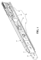
Fig. 1 is a perspective view to show the slide assembly of the present invention; -
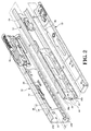
Fig. 2 is an exploded view to show the slide assembly of the present invention; -
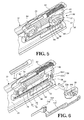
Fig. 3 is an exploded view to show the synchronic unit of the slide assembly of the present invention; -
Fig. 4 is an exploded view to show the hooking unit of the slide assembly of the present invention; -
Fig. 5 is an exploded view to show the movable unit of the slide assembly of the present invention; -
Fig. 6 is an exploded view to show part of the movable unit of the slide assembly of the present invention; -
Fig. 7 is a perspective view to show the passive unit of the slide assembly of the present invention; -
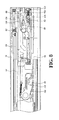
Fig. 8 is a perspective view to show that the slide assembly of the present invention is completely retracted; -
Fig. 9 shows the slide assembly of the present invention wherein the third rail is pushed; -
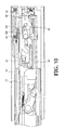
Fig. 10 shows the slide assembly of the present invention wherein the third rail is pushed and then released; -
Fig. 11 shows another status of the slide assembly of the present invention wherein the third rail is pushed and then released; -
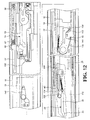
Fig. 12 shows that the third rail is pushed and then pulled, and the second rail is also pulled with the third rail; -
Fig. 13 shows that the third rail is pushed and then pulled, and the second rail is also pulled with the third rail, the passive unit and the synchronic unit are activated; -
Fig. 14 shows that the third rail is pushed and then pulled, and the second rail is also pulled with the third rail, the movable member of the passive unit is activated; -
Fig. 15 shows the two respective statuses of the passive unit and the synchronic unit when the third and second rails are pushed and retracted into the first rail; -
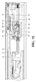
Fig. 16 shows the status of the movable unit when the third and second rails are pushed and retracted into the first rail; -
Fig. 17 shows that the movable member of the movable unit is pushed back to its initial position by the contact member when the third and second rails are pushed and retracted into the first rail; -
Fig. 18 shows that the link of the passive unit is pushed back to its initial position when the third and second rails are pushed and retracted into the first rail; -
Fig. 19 shows that the slide assembly of the present invention has a buffering member, and -
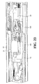
Fig. 20 shows that the buffering member is functioned to the second rail. - Referring to
Figs. 1 and2 , the self-opening and self-closing slide assembly of the present invention comprises afirst rail 10, a first bearing assembly 12, asecond rail 14, a second bearing assembly 16, athird rail 18 and an open-close device 20. The first bearing assembly 12 is connected to thefirst rail 10 so that thesecond rail 14 is slidably connected to thefirst rail 10. The second bearing assembly 16 is connected to thesecond rail 14 so that thethird rail 18 is slidably connected to thesecond rail 14. - The
first rail 10 has atop wall 22a,bottom wall 22b, aside wall 24, arelease portion 26 and aguide groove 28. Theside wall 24 is connected between the top andbottom walls top wall 22a, thebottom wall 22b and theside wall 24 define afirst passage 30. Therelease portion 26 is located on theside wall 24 and in thefirst passage 30. Theguide groove 28 is located on theside wall 24 and has alongitudinal groove 32 and atransverse groove 34 which is located at the distal end of thelongitudinal groove 32 and communicates with thelongitudinal groove 32. - The
second rail 14 is slidably connected to thefirst passage 30 of thefirst rail 10 by the first bearing assembly 12. Thesecond rail 14 comprises atop wall 36a, abottom wall 36b, aside wall 38, aprotrusion 40 and awindow 42 as shown inFig. 3 . Theside wall 38 is connected between the top andbottom walls second rail 14. Thetop wall 36a, thebottom wall 36b and theside wall 38 define asecond passage 44. Theprotrusion 40 is connected to theside wall 38 of thesecond rail 14 and faces thefirst passage 30 of thefirst rail 10. Thewindow 42 is defined in an end of theside wall 38. - The
third rail 18 is slidably connected to thesecond passage 44 of thesecond rail 14 by the second bearing assembly 16, and has apush block 46 and anopening 48 as shown inFig. 4 . Thepush block 46 faces thesecond passage 44 of thesecond rail 14. - The open-
close device 20 comprises amovable unit 50, apassive unit 52, asynchronic unit 54 and a hookingunit 56. - The
movable unit 50, as shown inFig. 5 and 6 , comprises abase 58, a fixingframe 60, a firstresilient member 62, apush member 64, amovable member 66 and a secondresilient member 68. Thebase 58 is connected to one end of theside wall 24 of thefirst rail 10 and comprises alongitudinal section 70, aroom 72 and aguide passage 74. The distal end of thelongitudinal section 70 has astop portion 76. Theroom 72 is substantially parallel to thelongitudinal section 70. Theguide passage 74 has alongitudinal guide groove 78 and atransverse guide groove 80 which is located at the distal end of thelongitudinal guide rove 78 and communicates with thelongitudinal guide groove 78. - The fixing
frame 60 is connected to thebase 58 and comprises alongitudinal rod 82. - The first
resilient member 62 is mounted to thelongitudinal rod 82 and has one end thereof contacting the fixingframe 60. - The
push member 64 is slidably connected to thelongitudinal section 70 of thebase 58 and movably mounted to thelongitudinal rod 82 of the fixingframe 60 and contacts the firstresilient member 62. When thepush member 64 is pushed to compress the firstresilient member 62, the firstresilient member 62 generates a force in a first direction and the force is applied to thepush member 64. - The
movable member 66 is movably connected to thebase 58 and has afirst leg 84a, asecond leg 84b, aguide path 86 and an engagingportion 88. Thefirst leg 84a and thesecond leg 84b are respectively located corresponding to theguide passage 74 and theroom 72 of thebase 58. The initial status of thefirst leg 84a is contacting thelongitudinal guide groove 78 of theguide passage 74 and thesecond leg 84b is located in theroom 72 of thebase 58. Theguide path 86 has a firstlongitudinal guide path 90, a secondlongitudinal guide path 92 and a mediatepath 94. The first and secondlongitudinal guide paths portion 88. The mediatepath 94 communicates with the first and secondlongitudinal guide paths portion 88. Preferably, themovable member 66 has a drivingend 96 which is located close to the engagingportion 88. - The second
resilient member 68 is located in theroom 72 of thebase 58. When thesecond leg 84b moves to compress the secondresilient member 68, the secondresilient member 68 is compressed by thesecond leg 84b and generates a force in a second direction. The force of the secondresilient member 68 is applied to thesecond leg 84b. The first and second directions are in opposite to each other. - A preferable embodiment further comprises a threaded
block 98 and anadjustment member 100 both located corresponding to theroom 72. Theadjustment member 100 has a threadedrod 102 and a head 104 which extends from one end of the threadedrod 102. The threadedrod 102 of theadjustment member 100 threadedly extends through the threadedblock 98, so that the threadedrod 102 in theroom 72 contacts thesecond leg 84b of themovable member 66. When the user rotates the head 104 of theadjustment member 100, the threadedrod 102 is moved forward or backward relative to theroom 72 such that the initial position of thesecond leg 84b in theroom 72 of the base 58 can be adjusted. - The
passive unit 52, as shown inFig. 7 , has alink 106, aconnection unit 108 and afirst spring 110. Thelink 106 has afirst protrusion 112 and asecond protrusion 114. Thefirst protrusion 112 is located in theguide groove 28 of thefirst rail 10. Thesecond protrusion 114 is located longitudinally and corresponding to theprotrusion 40 of thesecond rail 14. Theconnection unit 108 is connected between themovable member 66 and thelink 106. In a preferable embodiment, theconnection unit 108 comprises afirst connector 116 and asecond connector 118 which is connected to thefirst connector 116. Thefirst connector 116 is fixed to themovable member 66 by a fixingmember 120 as shown inFig. 6 . Thesecond connector 118 is pivotably connected to thelink 106. Thefirst spring 110 is connected between thelink 106 and thesecond connector 118 of theconnection unit 108. In a preferable embodiment, thelink 106 has afirst hook 122 and thesecond connector 118 has asecond hook 124. Thefirst spring 110 is hooked between the first andsecond hooks - In a preferable embodiment, the
movable unit 52 comprises asupport member 126 fixed to theside wall 24 of thefirst rail 10 and has asupport passage 128 in which thesecond connector 118 is movably located. Thesupport member 126 has at least onestop wall 130 to maintain thesecond connector 118 in thesupport passage 128 of thesupport member 126. - The
synchronic unit 54, as shown inFig. 3 , has asynchronic member 132 and asecond spring 134. Thesynchronic member 132 is pivotably connected to theside wall 38 of thesecond rail 14 by apivot 136 and has afirst contact portion 138 and asecond contact portion 140. Thefirst contact portion 138 extends through thewindow 42 of thesecond rail 14 and toward theside wall 24 of thefirst rail 10. Thefirst contact portion 138 of thesynchronic member 132 has aninclined face 142 which is located corresponding to therelease portion 26 of thefirst rail 10. Thesecond contact portion 140 is located corresponding to thepush block 46 of thethird rail 18. Thesecond spring 134 is connected between thesynchronic member 132 and thesecond rail 14. In a preferable embodiment, thesynchronic member 132 has athird hook 144 and thesecond rail 14 has afourth hook 146. Thesecond spring 134 is hooked between the third andfourth hooks - The hooking
unit 56, as shown inFig. 4 , has a hookingmember 148, acover 150 and acontact member 152. The hookingmember 148 is pivotably connected to thecover 150 by apin 156. Thecover 150 is securely connected to thethird rail 18 and located corresponding to theopening 48 of thethird rail 18. Thecover 150 has acurved slot 158 which is located corresponding to the hookingportion 154 of the hookingmember 148. The hookingportion 154 of the hookingmember 148 extends through thecurved slot 158 and is movable within thecurved slot 158. Thecontact member 152 is fixed to thethird rail 18 and located corresponding to the drivingend 96 of themovable member 66. - As shown in
Fig. 8 , when thethird rail 18 is located at a retracted position relative to thefirst rail 10, thesecond rail 14 is retracted in thefirst rail 10. The hookingportion 154 of the hookingmember 148 is engaged with the engagingportion 88 of themovable member 66. The secondresilient member 68 contacts thesecond leg 84b of themovable member 66. Thepush member 64 is pushed by thesecond rail 14 and compresses the firstresilient member 62, the firstresilient member 62 generates a force in a first direction F1 and the force is applied to thepush member 64. Under the retracted status, thepush block 46 of thethird rail 18 is located corresponding to thesecond contact portion 140 of thesynchronic member 132 of thesecond rail 14. The firstresilient member 62 stores a force relative to thesecond rail 14. The force of the secondresilient member 68 is applied to themovable member 66. Thesecond leg 84b of themovable member 66 contacts the threadedrod 102 of theadjustment member 100. - As shown in
Fig. 9 , when thethird rail 18 is pushed by a pushing force F (as shown in the direction shown by the arrow head), the hookingportion 154 of the hookingmember 148 is disengaged from the engagingportion 88 of themovable member 66 and is moved to the firstlongitudinal guide path 90 of themovable member 66. When the pushing force is disappeared, the force in the first direction F1 of the firstresilient member 62 is released, as shown inFigs. 10 and11 , thesecond rail 14 is pushed by thepush member 64 and thethird rail 18 is also moved by thesecond rail 14 relative to thefirst rail 10. - As shown in
Fig. 11 , when thethird rail 18 is continuously pulled relative to thefirst rail 10, as shown inFigs. 12 and13 , thepush block 46 of thethird rail 18 contacts thesecond contact portion 140 of thesynchronic member 132 so that thesecond rail 14 is pulled along with the movement of thethird rail 18. Theprotrusion 40 of thesecond rail 14 pushes thesecond protrusion 114 of thelink 106 so that along with the continuous movement of thesecond rail 14, thefirst protrusion 112 of thelink 106 moves along thelongitudinal groove 32 of theguide groove 28 of thefirst rail 10. As shown inFigs. 13 and14 , theconnection unit 108 is connected between themovable member 66 is moved by thelink 106, themovable member 66 moves along thelongitudinal guide groove 78 of theguide passage 74 of thebase 58. When thefirst protrusion 112 is guided and engaged with thetransverse groove 34 of theguide groove 28, theprotrusion 40 of thesecond rail 14 presses on the top of thesecond protrusion 114 of thelink 106. Thefirst protrusion 112 of thelink 106 is located in thetransverse groove 34 of theguide groove 28. Themovable member 66 is guided and moved, thefirst leg 84a is located in thetransverse guide groove 80 of theguide passage 74 and the secondresilient member 68 is compressed by thesecond leg 84b and generates a force in the second direction F2. - As shown in
Fig. 13 , when thefirst contact portion 138 of thesynchronic member 132 contacts therelease portion 26 of thefirst rail 10, thefirst contact portion 138 contacts therelease portion 26 by theinclined face 142 and is temporarily positioned. Thesynchronic member 132 swings an angle and thesecond contact portion 140 of thesynchronic member 132 is disengaged from thepush block 46 of thethird rail 18. Therefore, thethird rail 18 can be completely pulled relative to thefirst rail 10 and the distance is prolonged by thesecond rail 14. - As shown in
Fig. 15 , when thethird rail 18 is retracted relative to thefirst rail 10, thethird rail 18 is first retracted into thesecond rail 14, and then thethird rail 18 and thesecond rail 14 are retracted relative to thefirst rail 10. Thepush block 46 of thethird rail 18 moves to the position where thepush block 46 is located corresponding to thesecond contact portion 140 of thesynchronic member 132. Thefirst contact portion 138 of thesynchronic member 132 is separated from therelease portion 26 of thefirst rail 10. Theprotrusion 40 of thesecond rail 14 does not press on thesecond protrusion 114 of thelink 106 after thesecond rail 14 moves. - As shown in
Figs. 16 and17 , when the second andthird rails first rail 10, and thecontact member 152 pushes the drivingend 96 of themovable member 66 so that thefirst leg 84a of themovable member 66 is disengaged from thetransverse guide groove 80 of theguide passage 74 and the hookingportion 154 of the hookingmember 148 is moved to the secondlongitudinal guide path 92 of themovable member 66 and contacts the engagingportion 88 of themovable member 66. The force of the secondresilient member 68 in the second direction F2 is applied to themovable member 66, the engagingportion 88 of themovable member 66 contacts the hookingportion 154 of the hookingmember 148 to retract thethird rail 18 relative to thefirst rail 10 to the status as shown inFig. 8 . - Alternatively, as shown in
Fig. 17 , aconnection unit 108 is connected to themovable member 66 and thelink 106 so that themovable member 66 moves thelink 106 as shown inFig. 18 . Thefirst protrusion 112 of themovable member 66 removes from thetransverse groove 34 of theguide groove 28 and returns to thelongitudinal groove 32 of theguide groove 28. Thefirst spring 110 provides assistance to allow thelink 106 to swing smoothly. - As shown in
Figs. 19 ,20 , a preferable embodiment further comprises abuffering member 160 connected to thefirst rail 10 and comprises aplunger 162 which is extendable from the bufferingmember 160. Theplunger 162 is located corresponding to thesecond rail 14 and the distance that theplunger 162 extends forms a buffering travel to thesecond rail 14. When thesecond rail 14 is retracted with thethird rail 18 relative to thefirst rail 10, theplunger 162 contacts thesecond rail 14 so that the retraction action of the slide assembly is more stable. - While we have shown and described the embodiment in accordance with the present invention, it should be clear to those skilled in the art that further embodiments may be made without departing from the scope of the present invention.
Claims (9)
- A self-opening and self-closing slide assembly comprising:a first rail (10) having a side wall (24), a release portion (26), a guide groove (28) and a first passage (30), the release portion (26) located on the side wall (24) and in the first passage (30), the guide groove (28) located on the side wall (24) and having a longitudinal groove (32) and a transverse groove (34) which communicates with the longitudinal groove (32);a second rail (14) slidably connected to the first rail (10) and having a side wall (38), a protrusion (40) and a second passage (44), the protrusion (40) connected to the side wall (38) of the second rail (14) and facing the first passage (30) of the first rail (10);a third rail (18) slidably connected to the second rail (14) and having a push block (46) facing the second passage (44) of the second rail (14);a movable unit (50) having a base (58), a first resilient member (62), a push member (64), a movable member (66) and a second resilient member (68), the base (58) connected to the side wall (24) of the first rail (10) and having a longitudinal section (70), a room (72) and a guide passage (74), the room (72) substantially parallel to the longitudinal section (70), the guide passage (74) having a longitudinal guide groove (78) and a transverse guide groove (80) which communicates with the longitudinal guide groove (78), the first resilient member (62) being biased between the base (58) and the push member (64), the push member (64) located corresponding to the second rail (14), the movable member (66) movably connected to the base (58) and having a first leg (84a), a second leg (84b), a guide path (86) and an engaging portion (88), the first leg (84a) and the second leg (84b) respectively located corresponding to the guide passage (74) and the room (72) of the base (58), the guide path (86) having a first longitudinal guide path (90), a second longitudinal guide path (92) and a mediate path (94), the first and second longitudinal guide paths (90, 92) located on two sides of the engaging portion (88), the mediate path (94) communicating with the first and second longitudinal guide paths (90, 92) and located corresponding to the engaging portion (88), the second resilient member (68) located in the room (72) of the base (58) and contacting the second leg (84b) of the movable member (66);a passive unit (52) having a link (106), a connection unit (108) and a first spring (110), the link (106) having a first protrusion (112) and a second protrusion (114), the first protrusion (112) located in the guide groove (28) of the first rail (10), the second protrusion (114) located corresponding to the protrusion (40) of the second rail (14), the connection unit (108) connected between the movable member (66) and the link (106), the first spring (110) connected between the link (106) and the connection unit (108);a synchronic unit (54) having a synchronic member (132) and a second spring (134), the synchronic member (132) pivotably connected to the second rail (14) and having a first contact portion (138) and a second contact portion (140), the first contact portion (138) facing the side wall (24) of the first rail (10) and located corresponding to the release portion (26), the second contact portion (140) located corresponding to the push block (46) of the third rail (18), the second spring (134) connected between the synchronic member (132) and the second rail (14);a hooking unit (56) having a hooking member (148) and a contact member (152), the hooking member (148) pivotably connected to the third rail (18) and having a hooking portion (154), the contact member (152) fixed to the third rail (18) and located corresponding to the movable member (66);when the third rail (18) is located at a retracted position relative to the first rail (10), the second rail (14) is retracted in the first rail (10), the hooking portion (154) of the hooking member (148) is engaged with the engaging portion (88) of the movable member (66), the push member (64) is pushed by the second rail (14) and compresses the first resilient member (62), the first resilient member (62) generates a force in a first direction and the force is applied to the push member (64), the second leg (84b) of the movable member (66) contacts the second resilient member (68), the push block (46) of the third rail (18) is located corresponding to the second contact portion (140) of the synchronic member (132);wherein, when the third rail (18) is pushed by a pushing force, the hooking portion (154) of the hooking member (148) is disengaged from the engaging portion (88) of the movable member (66) and is moved to the first longitudinal guide path (90) of the movable member (66), when the pushing force is disappeared, the force in the first direction of the first resilient member (62) is released, the second rail (14) is pushed by the push member (64) and moves relative to the first rail (10), when the third rail (18) is continuously pulled, the push block (46) of the third rail (18) contacts the second contact portion (140) of the synchronic member (132) so that the second rail (14) is pulled along with movement of the third rail (18), the protrusion (40) of the second rail (14) pushes the second protrusion (114) of the link (106) so that the first protrusion (112) of the link (106) moves along the longitudinal groove (32) of the guide groove (28) of the first rail (10), the movable member (66) is moved by the link (106) and the connection unit (108), the movable member (66) moves along the longitudinal guide groove (78) of the guide passage (74) of the base (58), when the first protrusion (112) is engaged with the transverse groove (34) of the guide groove (28), the protrusion (40) of the second rail (14) presses on a top of the second protrusion (114) of the link (106), the first leg (84a) is located in the transverse guide groove (80) of the guide passage (74) and the second resilient member (68) is compressed by the second leg (84b) and generates a force in a second direction, when the first contact portion (138) of the synchronic member (132) contacts the release portion (26) of the first rail (10), the synchronic member (132) swings an angle and the second contact portion (140) of the synchronic member (132) is disengaged from the push block (46) of the third rail (18), andwherein, when the third rail (18) is retracted relative to the first rail (10), the first contact portion (138) of the synchronic member (132) is separated from the release portion (26) of the first rail (10) and the second contact portion (140) returns to a position located corresponding to the push block (46), when the contact member (152) pushes the movable member (66), the movable member (66) is disengaged from the transverse guide groove (80) of the guide passage (74) and the hooking portion (154) of the hooking member (148) contacts the engaging portion (88) of the movable member (66), the force of the second resilient member (68) retracts the third rail (18) relative to the first rail (10) and the first protrusion (112) of the link (106) is separated from the transverse groove (34) of the guide groove (28).
- The slide assembly as claimed in claim 1 further comprising a threaded block (98) and an adjustment member (100) both located corresponding to the room (72), the adjustment member (100) having a threaded rod (102) and a head (104) which extends from an end of the threaded rod (102), the threaded rod (102) of the adjustment member (100) threadedly extending through the threaded block (98), the threaded rod (102) in the room (72) contacting the second leg (84b) of the movable member (66).
- The slide assembly as claimed in claim 1, wherein the connection unit (108) comprises a first connector (116) and a second connector (118) which is connected to the first connector (116), the first connector (116) is fixed to the movable member (66) by a fixing member (120), the second connector (118) is pivotably connected to the link (106).
- The slide assembly as claimed in claim 3, wherein the link (106) has a first hook (122) and the second connector (118) has a second hook (124), the first spring (110) is hooked between the first and second hooks (122, 124).
- The slide assembly as claimed in claim 3, wherein a support member (126) is fixed to the side wall (24) of the first rail (10) and has a support passage (128) in which the second connector (118) is movably located, the support member (126) has at least one stop wall (130) to maintain the second connector (118) in the support passage (128).
- The slide assembly as claimed in claim 1, wherein the side wall (38) of the second rail (14) has a window (42) and the synchronic member (132) is located beside the window (42) and pivotably connected to the second rail (14) by a pivot (136), the first contact portion (138) of the synchronic member (132) extends through the window (42) and toward the side wall (24) of the first rail (10).
- The slide assembly as claimed in claim 6, wherein the first contact portion (138) of the synchronic member (132) has an inclined face (142) which is located corresponding to the release portion (26) of the first rail (10), the synchronic member (132) has a third hook (144) and the second rail (14) has a fourth hook (146), the second spring (134) is hooked between the third and fourth hooks (144, 146).
- The slide assembly as claimed in claim 1, wherein the third rail (18) has an opening (48), the hooking unit (56) comprises a cover (150) which is located corresponding to the opening (48) is fixed to the third rail (18), the hooking member (148) is pivotably connected to the cover (150) by a pin (156), the cover (150) has a curved slot (158) which is located corresponding to the hooking portion (154) of the hooking member (148), the hooking portion (154) of the hooking member (148) extends through the curved slot (158).
- The slide assembly as claimed in claim 1, wherein a buffering member (160) is connected to the first rail (10) and comprises a plunger (162) which is extendable from the buffering member (160), a distance that the plunger (162) extends forms a buffering travel to the second rail (14).
Priority Applications (2)
| Application Number | Priority Date | Filing Date | Title |
|---|---|---|---|
| EP12184222.3A EP2708156B1 (en) | 2012-09-13 | 2012-09-13 | Self-opening and self-closing slide assembly |
| ES12184222.3T ES2529993T3 (en) | 2012-09-13 | 2012-09-13 | Sliding assembly with automatic opening and automatic closing |
Applications Claiming Priority (1)
| Application Number | Priority Date | Filing Date | Title |
|---|---|---|---|
| EP12184222.3A EP2708156B1 (en) | 2012-09-13 | 2012-09-13 | Self-opening and self-closing slide assembly |
Publications (2)
| Publication Number | Publication Date |
|---|---|
| EP2708156A1 true EP2708156A1 (en) | 2014-03-19 |
| EP2708156B1 EP2708156B1 (en) | 2014-11-12 |
Family
ID=46888322
Family Applications (1)
| Application Number | Title | Priority Date | Filing Date |
|---|---|---|---|
| EP12184222.3A Active EP2708156B1 (en) | 2012-09-13 | 2012-09-13 | Self-opening and self-closing slide assembly |
Country Status (2)
| Country | Link |
|---|---|
| EP (1) | EP2708156B1 (en) |
| ES (1) | ES2529993T3 (en) |
Cited By (1)
| Publication number | Priority date | Publication date | Assignee | Title |
|---|---|---|---|---|
| CN107019356A (en) * | 2016-02-01 | 2017-08-08 | 川湖科技股份有限公司 | Sliding rail assembly |
Citations (6)
| Publication number | Priority date | Publication date | Assignee | Title |
|---|---|---|---|---|
| US7249813B2 (en) | 2003-04-25 | 2007-07-31 | Julius Blum Gesellschaft M.B.H. | Retraction device for drawers |
| US7374261B1 (en) | 2006-12-08 | 2008-05-20 | Dynaslide Corporation | Push-open type slide structure |
| EP2279680A1 (en) * | 2009-07-28 | 2011-02-02 | Paul Hettich GmbH & Co. KG | Opening and closing device |
| CA2698505A1 (en) * | 2010-03-31 | 2011-09-30 | King Slide Works Co., Ltd. | Opening device for a slide assembly |
| EP2428135A1 (en) * | 2010-09-13 | 2012-03-14 | King Slide Works Co., Ltd. | Slide assembly with buffering device |
| US8172345B2 (en) | 2009-07-20 | 2012-05-08 | King Slide Works Co., Ltd. | Self-moving device for movable furniture parts |
-
2012
- 2012-09-13 EP EP12184222.3A patent/EP2708156B1/en active Active
- 2012-09-13 ES ES12184222.3T patent/ES2529993T3/en active Active
Patent Citations (6)
| Publication number | Priority date | Publication date | Assignee | Title |
|---|---|---|---|---|
| US7249813B2 (en) | 2003-04-25 | 2007-07-31 | Julius Blum Gesellschaft M.B.H. | Retraction device for drawers |
| US7374261B1 (en) | 2006-12-08 | 2008-05-20 | Dynaslide Corporation | Push-open type slide structure |
| US8172345B2 (en) | 2009-07-20 | 2012-05-08 | King Slide Works Co., Ltd. | Self-moving device for movable furniture parts |
| EP2279680A1 (en) * | 2009-07-28 | 2011-02-02 | Paul Hettich GmbH & Co. KG | Opening and closing device |
| CA2698505A1 (en) * | 2010-03-31 | 2011-09-30 | King Slide Works Co., Ltd. | Opening device for a slide assembly |
| EP2428135A1 (en) * | 2010-09-13 | 2012-03-14 | King Slide Works Co., Ltd. | Slide assembly with buffering device |
Cited By (1)
| Publication number | Priority date | Publication date | Assignee | Title |
|---|---|---|---|---|
| CN107019356A (en) * | 2016-02-01 | 2017-08-08 | 川湖科技股份有限公司 | Sliding rail assembly |
Also Published As
| Publication number | Publication date |
|---|---|
| EP2708156B1 (en) | 2014-11-12 |
| ES2529993T3 (en) | 2015-02-25 |
Similar Documents
| Publication | Publication Date | Title |
|---|---|---|
| US8801120B2 (en) | Self-opening and self-closing slide assembly | |
| US8240789B2 (en) | Positioning device for slide assembly | |
| US8172345B2 (en) | Self-moving device for movable furniture parts | |
| US9364089B1 (en) | Self-closing slide rail assembly with deceleration mechanism | |
| US8496306B2 (en) | Opening mechanism of slide assembly | |
| US8147010B2 (en) | Slide assembly having an automatic retractable device | |
| US8308251B2 (en) | Elastic force adjustment device for slide assembly | |
| EP2201863B1 (en) | Self-moving device for movable furniture parts | |
| US20180087305A1 (en) | Ejection device for a movable furniture part | |
| US20130058596A1 (en) | Slide assembly with positioning device | |
| JP2017086858A (en) | Driving mechanism and driving method for furniture | |
| GB2459762A (en) | A retraction mechanism for a drawer | |
| JP2017086859A (en) | Drive mechanism | |
| CN104207507A (en) | Restraining device | |
| CN103653891B (en) | Slide rail assembly and self-opening and closing slide rail assembly | |
| EP2532272B1 (en) | Opening mechanism of slide assembly | |
| CN104822296A (en) | Device for moving movable furniture part | |
| TWI457094B (en) | Self opening and closing mechanism for slide rail assembly | |
| JP3193308U (en) | Self-closing device and slide rail kit using the same | |
| EP2708156B1 (en) | Self-opening and self-closing slide assembly | |
| US7588299B2 (en) | Rail assembly for drawers | |
| EP3025615B1 (en) | Self-closing slide rail assembly with deceleration mechanism | |
| JP3179942U (en) | Automatic opening and closing slide rail kit | |
| JP3196135U (en) | Self-closing slide rail kit | |
| EP2389837B1 (en) | Elastic force adjustment device for slide assembly |
Legal Events
| Date | Code | Title | Description |
|---|---|---|---|
| PUAI | Public reference made under article 153(3) epc to a published international application that has entered the european phase |
Free format text: ORIGINAL CODE: 0009012 |
|
| 17P | Request for examination filed |
Effective date: 20130507 |
|
| AK | Designated contracting states |
Kind code of ref document: A1 Designated state(s): AL AT BE BG CH CY CZ DE DK EE ES FI FR GB GR HR HU IE IS IT LI LT LU LV MC MK MT NL NO PL PT RO RS SE SI SK SM TR |
|
| AX | Request for extension of the european patent |
Extension state: BA ME |
|
| GRAP | Despatch of communication of intention to grant a patent |
Free format text: ORIGINAL CODE: EPIDOSNIGR1 |
|
| RIC1 | Information provided on ipc code assigned before grant |
Ipc: A47B 88/04 20060101AFI20140623BHEP |
|
| INTG | Intention to grant announced |
Effective date: 20140708 |
|
| GRAS | Grant fee paid |
Free format text: ORIGINAL CODE: EPIDOSNIGR3 |
|
| GRAA | (expected) grant |
Free format text: ORIGINAL CODE: 0009210 |
|
| AK | Designated contracting states |
Kind code of ref document: B1 Designated state(s): AL AT BE BG CH CY CZ DE DK EE ES FI FR GB GR HR HU IE IS IT LI LT LU LV MC MK MT NL NO PL PT RO RS SE SI SK SM TR |
|
| REG | Reference to a national code |
Ref country code: GB Ref legal event code: FG4D |
|
| REG | Reference to a national code |
Ref country code: CH Ref legal event code: EP |
|
| REG | Reference to a national code |
Ref country code: AT Ref legal event code: REF Ref document number: 695210 Country of ref document: AT Kind code of ref document: T Effective date: 20141115 |
|
| REG | Reference to a national code |
Ref country code: IE Ref legal event code: FG4D |
|
| REG | Reference to a national code |
Ref country code: DE Ref legal event code: R096 Ref document number: 602012003745 Country of ref document: DE Effective date: 20141224 |
|
| REG | Reference to a national code |
Ref country code: ES Ref legal event code: FG2A Ref document number: 2529993 Country of ref document: ES Kind code of ref document: T3 Effective date: 20150225 |
|
| REG | Reference to a national code |
Ref country code: NL Ref legal event code: VDEP Effective date: 20141112 |
|
| PG25 | Lapsed in a contracting state [announced via postgrant information from national office to epo] |
Ref country code: FI Free format text: LAPSE BECAUSE OF FAILURE TO SUBMIT A TRANSLATION OF THE DESCRIPTION OR TO PAY THE FEE WITHIN THE PRESCRIBED TIME-LIMIT Effective date: 20141112 Ref country code: IS Free format text: LAPSE BECAUSE OF FAILURE TO SUBMIT A TRANSLATION OF THE DESCRIPTION OR TO PAY THE FEE WITHIN THE PRESCRIBED TIME-LIMIT Effective date: 20150312 Ref country code: NL Free format text: LAPSE BECAUSE OF FAILURE TO SUBMIT A TRANSLATION OF THE DESCRIPTION OR TO PAY THE FEE WITHIN THE PRESCRIBED TIME-LIMIT Effective date: 20141112 Ref country code: PT Free format text: LAPSE BECAUSE OF FAILURE TO SUBMIT A TRANSLATION OF THE DESCRIPTION OR TO PAY THE FEE WITHIN THE PRESCRIBED TIME-LIMIT Effective date: 20150312 Ref country code: LT Free format text: LAPSE BECAUSE OF FAILURE TO SUBMIT A TRANSLATION OF THE DESCRIPTION OR TO PAY THE FEE WITHIN THE PRESCRIBED TIME-LIMIT Effective date: 20141112 Ref country code: NO Free format text: LAPSE BECAUSE OF FAILURE TO SUBMIT A TRANSLATION OF THE DESCRIPTION OR TO PAY THE FEE WITHIN THE PRESCRIBED TIME-LIMIT Effective date: 20150212 |
|
| PG25 | Lapsed in a contracting state [announced via postgrant information from national office to epo] |
Ref country code: LV Free format text: LAPSE BECAUSE OF FAILURE TO SUBMIT A TRANSLATION OF THE DESCRIPTION OR TO PAY THE FEE WITHIN THE PRESCRIBED TIME-LIMIT Effective date: 20141112 Ref country code: SE Free format text: LAPSE BECAUSE OF FAILURE TO SUBMIT A TRANSLATION OF THE DESCRIPTION OR TO PAY THE FEE WITHIN THE PRESCRIBED TIME-LIMIT Effective date: 20141112 Ref country code: CY Free format text: LAPSE BECAUSE OF FAILURE TO SUBMIT A TRANSLATION OF THE DESCRIPTION OR TO PAY THE FEE WITHIN THE PRESCRIBED TIME-LIMIT Effective date: 20141112 Ref country code: PL Free format text: LAPSE BECAUSE OF FAILURE TO SUBMIT A TRANSLATION OF THE DESCRIPTION OR TO PAY THE FEE WITHIN THE PRESCRIBED TIME-LIMIT Effective date: 20141112 Ref country code: RS Free format text: LAPSE BECAUSE OF FAILURE TO SUBMIT A TRANSLATION OF THE DESCRIPTION OR TO PAY THE FEE WITHIN THE PRESCRIBED TIME-LIMIT Effective date: 20141112 Ref country code: HR Free format text: LAPSE BECAUSE OF FAILURE TO SUBMIT A TRANSLATION OF THE DESCRIPTION OR TO PAY THE FEE WITHIN THE PRESCRIBED TIME-LIMIT Effective date: 20141112 |
|
| PG25 | Lapsed in a contracting state [announced via postgrant information from national office to epo] |
Ref country code: DK Free format text: LAPSE BECAUSE OF FAILURE TO SUBMIT A TRANSLATION OF THE DESCRIPTION OR TO PAY THE FEE WITHIN THE PRESCRIBED TIME-LIMIT Effective date: 20141112 Ref country code: CZ Free format text: LAPSE BECAUSE OF FAILURE TO SUBMIT A TRANSLATION OF THE DESCRIPTION OR TO PAY THE FEE WITHIN THE PRESCRIBED TIME-LIMIT Effective date: 20141112 Ref country code: EE Free format text: LAPSE BECAUSE OF FAILURE TO SUBMIT A TRANSLATION OF THE DESCRIPTION OR TO PAY THE FEE WITHIN THE PRESCRIBED TIME-LIMIT Effective date: 20141112 Ref country code: SK Free format text: LAPSE BECAUSE OF FAILURE TO SUBMIT A TRANSLATION OF THE DESCRIPTION OR TO PAY THE FEE WITHIN THE PRESCRIBED TIME-LIMIT Effective date: 20141112 Ref country code: RO Free format text: LAPSE BECAUSE OF FAILURE TO SUBMIT A TRANSLATION OF THE DESCRIPTION OR TO PAY THE FEE WITHIN THE PRESCRIBED TIME-LIMIT Effective date: 20141112 |
|
| REG | Reference to a national code |
Ref country code: DE Ref legal event code: R097 Ref document number: 602012003745 Country of ref document: DE |
|
| PLBE | No opposition filed within time limit |
Free format text: ORIGINAL CODE: 0009261 |
|
| STAA | Information on the status of an ep patent application or granted ep patent |
Free format text: STATUS: NO OPPOSITION FILED WITHIN TIME LIMIT |
|
| 26N | No opposition filed |
Effective date: 20150813 |
|
| PG25 | Lapsed in a contracting state [announced via postgrant information from national office to epo] |
Ref country code: IT Free format text: LAPSE BECAUSE OF FAILURE TO SUBMIT A TRANSLATION OF THE DESCRIPTION OR TO PAY THE FEE WITHIN THE PRESCRIBED TIME-LIMIT Effective date: 20141112 |
|
| PG25 | Lapsed in a contracting state [announced via postgrant information from national office to epo] |
Ref country code: SI Free format text: LAPSE BECAUSE OF FAILURE TO SUBMIT A TRANSLATION OF THE DESCRIPTION OR TO PAY THE FEE WITHIN THE PRESCRIBED TIME-LIMIT Effective date: 20141112 |
|
| PG25 | Lapsed in a contracting state [announced via postgrant information from national office to epo] |
Ref country code: MC Free format text: LAPSE BECAUSE OF FAILURE TO SUBMIT A TRANSLATION OF THE DESCRIPTION OR TO PAY THE FEE WITHIN THE PRESCRIBED TIME-LIMIT Effective date: 20141112 Ref country code: LU Free format text: LAPSE BECAUSE OF FAILURE TO SUBMIT A TRANSLATION OF THE DESCRIPTION OR TO PAY THE FEE WITHIN THE PRESCRIBED TIME-LIMIT Effective date: 20150913 |
|
| REG | Reference to a national code |
Ref country code: CH Ref legal event code: PL |
|
| REG | Reference to a national code |
Ref country code: FR Ref legal event code: ST Effective date: 20160531 |
|
| REG | Reference to a national code |
Ref country code: AT Ref legal event code: UEP Ref document number: 695210 Country of ref document: AT Kind code of ref document: T Effective date: 20141112 |
|
| PG25 | Lapsed in a contracting state [announced via postgrant information from national office to epo] |
Ref country code: LI Free format text: LAPSE BECAUSE OF NON-PAYMENT OF DUE FEES Effective date: 20150930 Ref country code: CH Free format text: LAPSE BECAUSE OF NON-PAYMENT OF DUE FEES Effective date: 20150930 |
|
| PG25 | Lapsed in a contracting state [announced via postgrant information from national office to epo] |
Ref country code: FR Free format text: LAPSE BECAUSE OF NON-PAYMENT OF DUE FEES Effective date: 20150930 |
|
| REG | Reference to a national code |
Ref country code: DE Ref legal event code: R079 Ref document number: 602012003745 Country of ref document: DE Free format text: PREVIOUS MAIN CLASS: A47B0088040000 Ipc: A47B0088400000 |
|
| PG25 | Lapsed in a contracting state [announced via postgrant information from national office to epo] |
Ref country code: MT Free format text: LAPSE BECAUSE OF FAILURE TO SUBMIT A TRANSLATION OF THE DESCRIPTION OR TO PAY THE FEE WITHIN THE PRESCRIBED TIME-LIMIT Effective date: 20141112 |
|
| PG25 | Lapsed in a contracting state [announced via postgrant information from national office to epo] |
Ref country code: HU Free format text: LAPSE BECAUSE OF FAILURE TO SUBMIT A TRANSLATION OF THE DESCRIPTION OR TO PAY THE FEE WITHIN THE PRESCRIBED TIME-LIMIT; INVALID AB INITIO Effective date: 20120913 Ref country code: BG Free format text: LAPSE BECAUSE OF FAILURE TO SUBMIT A TRANSLATION OF THE DESCRIPTION OR TO PAY THE FEE WITHIN THE PRESCRIBED TIME-LIMIT Effective date: 20141112 Ref country code: SM Free format text: LAPSE BECAUSE OF FAILURE TO SUBMIT A TRANSLATION OF THE DESCRIPTION OR TO PAY THE FEE WITHIN THE PRESCRIBED TIME-LIMIT Effective date: 20141112 |
|
| PG25 | Lapsed in a contracting state [announced via postgrant information from national office to epo] |
Ref country code: GR Free format text: LAPSE BECAUSE OF FAILURE TO SUBMIT A TRANSLATION OF THE DESCRIPTION OR TO PAY THE FEE WITHIN THE PRESCRIBED TIME-LIMIT Effective date: 20141112 |
|
| PG25 | Lapsed in a contracting state [announced via postgrant information from national office to epo] |
Ref country code: BE Free format text: LAPSE BECAUSE OF FAILURE TO SUBMIT A TRANSLATION OF THE DESCRIPTION OR TO PAY THE FEE WITHIN THE PRESCRIBED TIME-LIMIT Effective date: 20141112 |
|
| PG25 | Lapsed in a contracting state [announced via postgrant information from national office to epo] |
Ref country code: MK Free format text: LAPSE BECAUSE OF FAILURE TO SUBMIT A TRANSLATION OF THE DESCRIPTION OR TO PAY THE FEE WITHIN THE PRESCRIBED TIME-LIMIT Effective date: 20141112 |
|
| PG25 | Lapsed in a contracting state [announced via postgrant information from national office to epo] |
Ref country code: AL Free format text: LAPSE BECAUSE OF FAILURE TO SUBMIT A TRANSLATION OF THE DESCRIPTION OR TO PAY THE FEE WITHIN THE PRESCRIBED TIME-LIMIT Effective date: 20141112 |
|
| REG | Reference to a national code |
Ref country code: DE Ref legal event code: R082 Ref document number: 602012003745 Country of ref document: DE Representative=s name: 2K PATENT- UND RECHTSANWAELTE PARTNERSCHAFT MB, DE |
|
| PGFP | Annual fee paid to national office [announced via postgrant information from national office to epo] |
Ref country code: TR Payment date: 20210312 Year of fee payment: 10 |
|
| PGFP | Annual fee paid to national office [announced via postgrant information from national office to epo] |
Ref country code: AT Payment date: 20210928 Year of fee payment: 10 Ref country code: IE Payment date: 20210708 Year of fee payment: 10 |
|
| PGFP | Annual fee paid to national office [announced via postgrant information from national office to epo] |
Ref country code: GB Payment date: 20210707 Year of fee payment: 10 Ref country code: DE Payment date: 20210712 Year of fee payment: 10 |
|
| PGFP | Annual fee paid to national office [announced via postgrant information from national office to epo] |
Ref country code: ES Payment date: 20211123 Year of fee payment: 10 |
|
| REG | Reference to a national code |
Ref country code: DE Ref legal event code: R119 Ref document number: 602012003745 Country of ref document: DE |
|
| REG | Reference to a national code |
Ref country code: AT Ref legal event code: MM01 Ref document number: 695210 Country of ref document: AT Kind code of ref document: T Effective date: 20220913 |
|
| GBPC | Gb: european patent ceased through non-payment of renewal fee |
Effective date: 20220913 |
|
| PG25 | Lapsed in a contracting state [announced via postgrant information from national office to epo] |
Ref country code: IE Free format text: LAPSE BECAUSE OF NON-PAYMENT OF DUE FEES Effective date: 20220913 Ref country code: DE Free format text: LAPSE BECAUSE OF NON-PAYMENT OF DUE FEES Effective date: 20230401 Ref country code: AT Free format text: LAPSE BECAUSE OF NON-PAYMENT OF DUE FEES Effective date: 20220913 |
|
| REG | Reference to a national code |
Ref country code: ES Ref legal event code: FD2A Effective date: 20231030 |
|
| PG25 | Lapsed in a contracting state [announced via postgrant information from national office to epo] |
Ref country code: GB Free format text: LAPSE BECAUSE OF NON-PAYMENT OF DUE FEES Effective date: 20220913 |
|
| PG25 | Lapsed in a contracting state [announced via postgrant information from national office to epo] |
Ref country code: ES Free format text: LAPSE BECAUSE OF NON-PAYMENT OF DUE FEES Effective date: 20220914 |
|
| PG25 | Lapsed in a contracting state [announced via postgrant information from national office to epo] |
Ref country code: ES Free format text: LAPSE BECAUSE OF NON-PAYMENT OF DUE FEES Effective date: 20220914 |