EP2707682B1 - A zero-heat-flux, deep tissue temperature measurement system - Google Patents
A zero-heat-flux, deep tissue temperature measurement system Download PDFInfo
- Publication number
- EP2707682B1 EP2707682B1 EP12715468.0A EP12715468A EP2707682B1 EP 2707682 B1 EP2707682 B1 EP 2707682B1 EP 12715468 A EP12715468 A EP 12715468A EP 2707682 B1 EP2707682 B1 EP 2707682B1
- Authority
- EP
- European Patent Office
- Prior art keywords
- probe
- heater
- zero
- heat
- temperature
- Prior art date
- Legal status (The legal status is an assumption and is not a legal conclusion. Google has not performed a legal analysis and makes no representation as to the accuracy of the status listed.)
- Active
Links
Images


Classifications
-
- G—PHYSICS
- G01—MEASURING; TESTING
- G01K—MEASURING TEMPERATURE; MEASURING QUANTITY OF HEAT; THERMALLY-SENSITIVE ELEMENTS NOT OTHERWISE PROVIDED FOR
- G01K13/00—Thermometers specially adapted for specific purposes
- G01K13/20—Clinical contact thermometers for use with humans or animals
-
- G—PHYSICS
- G01—MEASURING; TESTING
- G01K—MEASURING TEMPERATURE; MEASURING QUANTITY OF HEAT; THERMALLY-SENSITIVE ELEMENTS NOT OTHERWISE PROVIDED FOR
- G01K1/00—Details of thermometers not specially adapted for particular types of thermometer
- G01K1/16—Special arrangements for conducting heat from the object to the sensitive element
- G01K1/165—Special arrangements for conducting heat from the object to the sensitive element for application in zero heat flux sensors
-
- G—PHYSICS
- G01—MEASURING; TESTING
- G01K—MEASURING TEMPERATURE; MEASURING QUANTITY OF HEAT; THERMALLY-SENSITIVE ELEMENTS NOT OTHERWISE PROVIDED FOR
- G01K15/00—Testing or calibrating of thermometers
- G01K15/005—Calibration
-
- G—PHYSICS
- G01—MEASURING; TESTING
- G01K—MEASURING TEMPERATURE; MEASURING QUANTITY OF HEAT; THERMALLY-SENSITIVE ELEMENTS NOT OTHERWISE PROVIDED FOR
- G01K7/00—Measuring temperature based on the use of electric or magnetic elements directly sensitive to heat ; Power supply therefor, e.g. using thermoelectric elements
- G01K7/16—Measuring temperature based on the use of electric or magnetic elements directly sensitive to heat ; Power supply therefor, e.g. using thermoelectric elements using resistive elements
- G01K7/22—Measuring temperature based on the use of electric or magnetic elements directly sensitive to heat ; Power supply therefor, e.g. using thermoelectric elements using resistive elements the element being a non-linear resistance, e.g. thermistor
Definitions
- the subject matter relates to a system for measurement of deep tissue temperature (DTT) as an indication of the core body temperature of humans or animals. More particularly, the subject matter relates to constructions and operations of a zero-heat-flux DTT measurement system with a cable interface for connection to a disposable DTT probe.
- DTT deep tissue temperature
- Deep tissue temperature is a proxy measure for core temperature, which is the mass-weighted mean temperature of the body contents. It is desirable to maintain core body temperature in a normothermic range in many clinical situations. For example, during the perioperative cycle maintenance of normothermia has been shown to reduce the incidence of many adverse consequences of anesthesia and surgery, including surgical site infections and bleeding; accordingly, it is beneficial to monitor a patient's body core temperature before, during, and after surgery. Of course noninvasive measurement is highly desirable, for the safety and the comfort of a patient, and for the convenience of the clinician. Thus, it is most advantageous to obtain a noninvasive DTT measurement by way of a device placed on the skin.
- Noninvasive measurement of DTT by means of a zero-heat-flux device was described by Fox and Solman in 1971 ( Fox RH, Solman AJ. A new technique for monitoring the deep body temperature in man from the intact skin surface. J. Physiol. Jan 1971:212(2): pp 8-10 ). Because the measurement depends on the absence of heat flux through the skin area where measurement takes place, the technique is referred to as a "zero-heat-flux" (ZHF) temperature measurement.
- ZHF zero-heat-flux
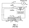
- the Fox/Solman system illustrated in FIG. 1 , estimates core body temperature using a ZHF temperature measurement device 10 including a pair of thermistors 20 separated by layer 22 of thermal insulation.
- a difference in the temperatures sensed by the thermistors 20 controls operation of a heater 24 of essentially planar construction that stops or blocks heat flow through a skin surface area contacted by the lower surface 26 of the device 10.
- a comparator 29 measures the difference in the sensed temperatures and provides the difference measurement to a controller 30.
- the heater 24 is operated for so long as the difference is non-zero. When the difference between the sensed temperatures reaches zero, the zero heat flux condition is satisfied, and the heater 24 is operated as needed to maintain the condition.
- the thermistor 20 at the lower surface 26 senses a temperature near, if not equal to, that of the skin surface area and its output is amplified at 36 and provided at 38 as the system output.
- Togawa improved the Fox/Solman measurement technique with a DTT measurement device structure that accounted for multidimensional heat flow in tissue.
- the Togawa device encloses a Fox and Solman-type ZHF design in a thick aluminum housing with a cylindrical annulus construction that reduces or eliminates radial heat flow from the center to the periphery of the device.
- the Fox/Solman and Togawa devices utilize heat flux normal to the body to control the operation of a heater that blocks heat flow from the skin through a thermal resistance in order to achieve a desired zero heat flux condition.
- the thermal mass added by Togawa's cover improves the stability of the Fox/Solman design and makes the measurement of deep tissue temperature more accurate. In this regard, since the goal is to achieve zero heat flux through the device, the more thermal resistance the better. However, the additional thermal resistance adds mass and size, and also increases the time required to reach a stable temperature.
- the size, mass, and cost of the Fox/Solman and Togawa devices do not promote disposability. Consequently, they must be sanitized after use, which exposes them to wear and tear and undetectable damage.
- the devices must also be stored for reuse. As a result, use of these devices raises the costs associated with zero-heat-flux DTT measurement and can pose a significant risk of cross contamination between patients. It is thus desirable to reduce the size and mass of a zero-heat-flux DTT measurement device, without compromising its performance, in order to promote disposability.
- a measurement device constructed according to the related applications is attached to the skin of a human or animal subject to sense the temperature of tissue deep under the skin.
- the measurement device is constituted of a flexible substrate and an electrical circuit disposed on a surface of the flexible substrate.
- the electrical circuit includes an essentially planar heater which is defined by an electrically conductive copper trace and which surrounds an unheated zone of the surface, a first thermal sensor disposed in the zone, a second thermal sensor disposed outside of the heater trace, a plurality of contact pads disposed outside of the heater trace, and a plurality of conductive traces that connect the first and second thermal sensors and the heater trace with the plurality of contact pads.
- Sections of the flexible substrate are folded together to place the first and second thermal sensors in proximity to each other.
- a layer of insulation disposed between the sections separates the first and second thermal sensors.
- the measurement device is oriented for operation so as to position the heater and the first thermal sensor on one side of the layer of insulation and the second thermal sensor on the other and in close proximity to an area of skin where a measurement is to be taken.
- the layout of the electrical circuit on a surface of the flexible substrate provides a low-profile, zero-heat-flux DTT measurement device that is essentially planar, even when the sections are folded together.
- Such devices are referred to as "sensors” or “probes”.
- sensors or "probes”.
- probe in order to avoid ambiguity with respect to the term "thermal sensor”, which is used in the specification to denote a device having an electrical property that changes in response to a change in temperature.
- DTT deep tissue temperature
- such a measurement system can have a construction customized for stand-alone operation. That is to say, one that does not include a standard signal output that can be accepted as an input by multi-function patient monitors.
- a standard signal output that can be accepted as an input by multi-function patient monitors.
- it is desirable that such an output signal interface conforming to a standard device or a standard input signal configuration defined for multi-function patient monitors would increase the versatility and usefulness of such a zero-heat-flux DTT measurement system.
- the disclosure concerns a zero-heat-flux DTT measurement system with a simple, low cost interface suitable for being used with disposable probes.
- the disclosure concerns simple, effective, and inexpensive system control mechanization for lightweight probes with low thermal mass.
- the disclosure concerns a zero-heat-flux DTT measurement system with a simple, low cost output signal interface conforming to a standard input signal configuration for multi-function patient monitors.
- a programmable memory for storing system information including thermal sensor calibration coefficients is located on the probe together with a heater and thermal sensors.
- a zero-heat-flux, DTT measurement system implementing control mechanization that checks signal continuity between the system and a probe, validates probe operation, determines skin and heater temperatures, and executes a control loop with safety measures related to measured skin and heater temperatures.
- a zero-heat-flux, DTT measurement system including an output signal interface conforming to a standard input signal configuration for multi-function patient monitor.
- the disclosure concerns a signal interface conforming to a standard device or a standard input signal configuration.
- This and other aspects are embodied in a system and method for emulating a standard thermistor output signal indicative of deep tissue temperature.
- a zero-heat-flux deep tissue temperature (DTT) measurement system measures internal body temperature by way of a zero-heat-flux DTT measurement probe that includes a heater and thermal sensors in a zero-heat-flux construction.
- the measurement system includes a processing and display unit with control mechanization that checks signal continuity with the probe, authenticates probe identity, decrements a use count of the probe, determines heater and skin temperatures based upon information obtained from the probe, and calculates a deep tissue temperature.
- the control loop implements safety measures related to measured temperatures and security measures related to integrity of data and probe use information associated with the probe.
- the measurement system includes a signal interface cable with an attached connector by which a probe can be physically, releasably, and electrically coupled to the system. The cable and connector together constitute a single element that is a removable and replaceable part of the system, separate from the probe.
- a standard output signal indicative of deep tissue temperature is provided by a measurement system emulation unit that imitates operation of a thermal sensor device.
- a zero-heat-flux DTT measurement probe (hereinafter, simply “a probe”) includes at least two thermal sensors, a heater, and a programmable memory device.
- a construction for such a probe includes a flexible substrate with at least two thermal sensors disposed thereon in a spaced-apart relationship.
- the thermal sensors are maintained in a spaced apart relationship on respective substrate layers by a flexible thermal insulator positioned between the layers.
- the substrate supports at least the thermal sensors, the separating thermal insulator; the programmable memory device, and the heater.
- the probe construction includes a periphery with a tab by which the probe is removeably coupled with a probe signal interface cable connector.
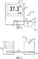
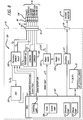
- a zero-heat-flux DTT measurement system 40 includes a processing and display unit 42 (hereinafter, "controller") and a probe 44.
- a signal interface cable 46 has first and second ends and a connector 48 mounted to the first end where a probe such as the probe 44 can be physically, removeably, and electrically coupled to the system.
- the signal interface cable 46 has a connector 50 mounted to the second end which can be inserted into and removed from a signal connector jack 52 in the controller 42.
- the signal interface cable 46 and connectors 48 and 50 are provided as a single integrated element that is a removable and replaceable part of the system, separate from the probe 44, and that are not formed together with the probe.
- a dongle 45 can be connected to and removed from the system by way of the signal interface cable 46, with connectors 48 and 50.
- the controller 42 has an output signal jack 54 where a cable 55 can be removeably plugged to conduct an output signal produced by an emulation unit to clinical equipment such as a multi-function patient monitor 56.
- the output signal is indicative of deep tissue temperature measured by the system 40 and conforms to a signal produced by an emulated temperature-responsive device.
- a manually-operated C/F button 59 on the rear surface of the controller 42 allows a system operator to select a scale (Celsius or Fahrenheit) for indicating temperature.
- the controller 42 includes information display elements by which measured temperatures, status indications, prompts, alarms and other system information are provided in visible form to a system operator.
- a multi-function display panel 43 of the liquid crystal type (LCD) displays a measured temperature.
- Zero-heat-flux DTT measurement probes that can be used in the zero-heat-flux DTT measurement system are preferably, but not necessarily, constructed according to the related applications.
- An example of a disposable probe representative of the probe 44 in FIG. 2 is shown in FIGS. 4-6 .
- a zero-heat-flux DTT measurement probe includes a flexible substrate supporting an electrical circuit in which a heater trace disposed on a first substrate layer defines a heater facing one side of a layer of thermally insulating material and surrounding a zone of the first substrate layer.
- a first thermal sensor is disposed in the zone, a programmable memory device is disposed on the first substrate layer outside of the heater, a second thermal sensor is disposed on the second substrate layer, a plurality of contact pads is disposed outside of the heater trace on a substrate surface, and a plurality of conductive traces connect the heater trace, the first and second thermal sensors and the programmable memory device to the contact pads.
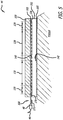
- FIG. 4 is a sectional, partially-schematic illustration of a preferred probe construction.
- FIG. 5 is a sectional, partially-schematic illustration of the preferred probe construction in which the section is rotated from the view of FIG. 4 .
- the probe 44 includes flexible substrate layers, a layer of thermally insulating material, and an electrical circuit.
- the electrical circuit includes a heater 126, a first thermal sensor 140, and a second thermal sensor 142.
- the heater 126 and the first thermal sensor 140 are disposed in or on a flexible substrate layer 103 and the second thermal sensor 142 is disposed in or on a flexible substrate layer 104.
- the first and second substrate layers 103 and 104 are separated by a flexible layer 102 of thermally insulating material.
- the flexible substrate layers 103 and 104 can be separate elements, but it is preferred that they be sections of a single flexible substrate folded around the layer of insulating material.
- adhesive film (not shown) attaches the substrate to the insulating layer 102.
- a layer of adhesive material 105 mounted to one side of the substrate layer 104 is provided with a removable liner (not shown) to attach the probe to skin.
- a flexible layer 109 of insulating material lies over the layers 102, 103, and 104 and is attached by adhesive film (not shown) to one side of the substrate layer 103.
- the insulating layer 109 extends over the heater 126 and the first thermal sensor 140.
- the electrical circuit further includes a programmable memory device 170 and contact pads 171 disposed in or on the flexible substrate layer 103.
- the programmable memory device 170 is positioned outside of the heater 126, preferably between the heater 126 and the contact pads 171.
- the contact pads 171 are positioned on a section 108 of the substrate layer 103 that projects beyond the insulating layer 109 so as to be detachably coupled with the connector 48 fixed to the first end of the cable 46.
- the programmable memory device 170 stores authentication data, thermal sensor calibration values, measured temperature data, probe use data, and other information.
- the thermal sensor calibration information includes one or more unique calibration coefficients for each thermistor.
- location of the programmable memory device 170 on the probe 44, between the heater 126 and the contact pads 171 permanently associates stored thermal sensor calibration information with the probe 44. Consequently, the need for a cable, with connector, permanently attached to the probe is eliminated.
- the cable 46 and connector 48 do not store unique calibration information, they can be used for any zero-heat-flux DTT measurement probe configured in accordance with the related applications.
- the probe 44 is disposed on a human or animal subject with the second thermal sensor 142 nearest the skin.
- the layer 102 is sandwiched between the first and second substrate layers 103 and 104 so as to separate the heater 126 and first thermal sensor 140 from the second thermal sensor 142.
- the layer 102 acts as a thermal resistance between the first and second thermal sensors, the second thermal sensor 142, located on the surface of the layer 102 that is closest to the skin, senses the temperature of the skin, and the first thermal sensor 140 senses the temperature at the opposing surface of the layer 102 away from the body.
- the heater While the temperature sensed by the first thermal sensor 140 is less than the temperature sensed by the second thermal sensor 142, the heater is operated to reduce heat flow through the layer 102 and the skin. When the temperature difference across the layer 102 is zero, heat flow through the layer 102 has been stopped. This is the zero-heat-flux condition as it is sensed by the first and second sensors 140 and 142. When the zero-heat-flux condition occurs, the temperature of the skin, indicated by the second thermal sensor, is interpreted as deep tissue temperature, if not core body temperature. When the zero heat flux condition is reached, the heater 126 is regulated as needed to maintain the condition. Preferably, but without limitation, the heater is regulated by changing the duty cycle of a square wave.
- a preferred construction of the substrate and electrical circuit portions of the probe 44 includes a flexible substrate 101 with contiguous sections 105, 106, and 108.
- the first, or center, section 105 is substantially circular in shape.
- the second section (or “tail”) 106 has the shape of a narrow, elongated rectangle with a bulbous end 107 that extends outwardly from the periphery of the center section 105 in a first direction.
- the third section (or "tab") is the extended section 108 seen in FIG. 5 .
- the tab 108 has the shape of a wide rectangle that extends outwardly from the periphery of the center section 105 in a second direction.
- Opposing notches 110 are formed in the tab 108 to receive and retain respective spring-loaded retainers of the connector 48.
- the tail 106 is displaced from the tab 108 by an arcuate distance of less than 180° in either a clockwise or a counterclockwise direction.
- an electrical circuit 120 is disposed on the flexible substrate 101.
- the elements of the electrical circuit 120 are located on the surface 121 of the flexible substrate 101.
- the electrical circuit 120 includes at least an electrically conductive heater trace, thermal sensors, a programmable memory device, electrically conductive connective trace portions, and mounting and contact pads.
- the heater trace 124 defines a generally annular heater 126 surrounding a zone 130 of the substrate 101 into which no portion of the heater trace 124 extends; in this regard, the zone 130 is not directly heated when the heater operates.
- the zone 130 occupies a generally circular portion of the surface 121. More completely, the zone 130 is a cylindrical section of the substrate 101 which includes the portion of the surface 121 seen in FIG.
- the zone 130 is centered in the center section 105 and is concentric with the heater 126.
- the first thermal sensor 140 is mounted on mounting pads formed in the zone 130.
- the second thermal sensor 142 is mounted on mounting pads disposed outside of the generally annular heater 126; preferably, these mounting pads are formed generally near the end of the tail 106, for example, in or near the center of the bulbous end 107 of the tail.
- the programmable memory device 170 includes at least one multi-pin electronic circuit device mounted on the probe 44.
- the programmable memory device 170 can be constituted of an electrically-erasable programmable read/write memory (EEPROM) mounted on mounting pads formed on a portion of the surface 121 on the center section 105 near or adjacent the tab 108.
- the contact pads 171 are formed on the surface 121, in the tab 108.
- a plurality of conductive trace portions connects the first and second thermal sensors, the programmable memory device 170, and the heater trace 124 with a plurality of the contact pads 171.
- at least one contact pad 171 is shared by the programmable memory device 170 and one of the heater 126, the first thermal sensor 140, and the second thermal sensor 142.
- the center section 105 has formed therein a plurality of slits 151, 152 to enhance the flexibility and conformability of the flexible substrate.
- the slits extend radially from the periphery toward the center of the center section 105.
- the slits define zones which move or flex independently of each other.
- the layout of the heater trace 124 is adapted to accommodate the slits.
- the heater trace follows a zigzag or switchback pattern with legs that increase in length from the periphery of the zone 130 to the ends of the longer slits 151 and then, after a step decrease at those ends, generally increase in length again to the outer periphery of the heater 126 in the zones defined by the slits.
- the construction of the heater has a generally annular shape centered in the zone 130, although the annularity is interrupted by the slits.
- the annular shape can be viewed as including a peripheral annulus of wedge-shaped heater zones surrounding a generally continuous central annulus.
- the heater 126 has a non-uniform power density construction that can be understood with reference to FIG. 6 .
- the heater 126 includes a central portion 128 (indicated by lightly drawn lines) having a first power density and a peripheral portion 129 (indicated by heavily drawn lines) which surrounds the central portion 128 and has a second power density higher than the first power density.
- the heater trace 124 is continuous and includes two ends, a first of which transitions to contact pad 5, and the second to contact pad 6.
- each of the central and peripheral portions 128 and 129 includes a plurality of sections arranged in a sequence, in which the sections of the central portion 128 alternate with the sections of the peripheral portion.
- the annular structure of the heater arrays the sections of the central portion 128 generally in a central annulus around the zone 130, and arrays the sections of the peripheral portion 129 around the central portion 128.
- the central portion 128 produces a central annulus of heat at the first power density surrounding the zone 130 and the peripheral portion 129 produces a ringshaped annulus of heat at the second power density that surrounds the central annulus of heat.
- the differing power densities of the heater portions 128 and 129 may be invariant within each portion; alternatively, they may vary. Variation of power density may be step-wise or continuous. Power density is most simply and economically established by the width of the heater trace 124 and/or the pitch (distance) between the legs of a switchback pattern. For example, the resistance, and therefore the power generated by the heater trace, varies inversely with the width of the trace. For any resistance, the power generated by the heater trace also varies inversely with the pitch of (distance between) the switchback legs.
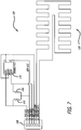
- the electrical circuit 120 on the flexible substrate 101 seen in FIG. 6 is shown in schematic form in FIG. 7 .
- the contact pads 171 on the tab 108 numbered 1-6 in FIG. 6 correspond to the identically-numbered elements in FIG. 7 .
- the number of contact pads shown is merely for illustration. More, or fewer, contact pads can be used; any specific number is determined by design choices including the specific device configuration of the programmable memory device, the heater construction, the number of thermal sensors, and so on. In some constructions it is desirable to utilize one or more of the contact pads for electrical signal conduction to or from more than a single element of the electrical circuit 120 in order to minimize the number of contact pads, thereby simplifying the circuit layout, minimizing the size and mass of the tab 108, and reducing interface connector size.
- the programmable memory device 170 includes a multi-pin EEPROM mounted by mounting pads to the probe 44.
- FIGS. 6 and 7 illustrate a construction in which one or more contact pads are shared by at least two elements of the electrical circuit. In this regard:
- the center section 105 and tail 106 are folded together about a flexible layer of insulating material such as the layer 102.
- the layer 102 provides thermal resistance and electrical insulation between the thermal sensors; it also supports the thermal sensors in a spaced-apart configuration.
- the first and second thermal sensors 140 and 142 are disposed on respective layers of substrate material that are separated by the layer of insulating material with the heater and first thermal sensor facing one side of the layer of insulating material and the second thermal sensor facing the other.
- the probe 44 with the electrical circuit 120 laid out on one or more sides of the flexible substrate 101 as illustrated in FIG. 4 , can be manufactured and assembled in the manner illustrated in the related applications, using materials identified in the Table of Materials and Parts.
- the probe is constructed with a stiffener comprising a separate piece or a layer of material painted, deposited, affixed, or formed on the tab 108 and then hardened.
- the stiffener reduces the flexibility of the tab 108, thereby enabling it to be reliably coupled to and decoupled from a connector.
- such a stiffener for the tab 108 is disposed on the outside surface of the flexible substrate 101 that corresponds to the second side of the flexible substrate 101.
- thermal sensors used in the detection of the zero-heat-flux condition. Given the importance of core body temperature, it is very desirable that the thermal sensors produce accurate temperature data in order to enable reliable detection of the zero-heat-flux condition and accurate estimation of core body temperature. In this case, the tradeoff is between accuracy and cost of the thermal sensor.
- a number of thermal sensor devices can be used in zero-heat-flux DTT measurement. These devices include PN junctions, resistive temperature devices, and thermistors, for example. Thermistors are a preferred choice for reasons of small size, handling convenience, ease of use, and reliability in the temperature range of interest. Their relatively low cost makes them desirable candidates for single-use, disposable probes.
- the magnitude of a thermistor's resistance changes in response to a change of the temperature of the thermistor.
- the thermistor's resistance is measured and converted to a temperature value using a known relationship.
- batch-to-batch manufacturing differences can yield a large variance in thermistor resistance.
- low-cost thermistors can exhibit a range of ⁇ 5% in resistance values from device to device at a given temperature, which yields a range of ⁇ 2.5° C in reported temperature.
- a variance can compromise the accuracy and reliability of zero-heat-flux temperature measurement.
- it is desirable to use such thermistors in order to limit the cost of parts and labor in manufacturing zero-heat-flux DTT probes it is important to correct for the effects of resistance variance on device operation.
- the range of thermistor resistance variance can be corrected by calibration of thermistor resistance using known methods, such as the Steinhart-Hart equation, which require knowledge of coefficients derived from values of thermistor resistance measured at fixed temperatures.
- the coefficients are used in known formulas to correct or adjust the magnitude of its indicated temperature. Such correction is called calibration.
- FIG. 6 and the corresponding electrical circuit of FIG. 7 illustrate location of a probe signal interface connection on the tab 108;
- FIG. 8 illustrates a signal interface between the probe 44 and the measurement system 40 that is established by releasably connecting the connector 48 to the signal interface location on the tab 108.
- the system 40 includes controller 200 and a signal interface that transfers power, common, and data signals between the controller 200 and the probe 44.
- the interface includes the cable 46 with the connector 48 releasably connected to the tab 108 and the connector 50 received in the signal connector jack 52.
- a separate signal path is provided for EEPROM ground, and the thermal sensor signal paths are shared with various pins of the EEPROM as per FIGS. 6 and 7 .
- This signal path configuration separates the digital ground for the EEPROM from the DC ground (common) for the heater, for good reason. Presume that the EEPROM and the heater share a contact pad for ground.
- the cable 46 including the contacts of the connector 48 has a certain amount of resistance. If the heater 126 is powered up, the current through it has to return to the controller 200 through the ground (common) contact, which means there will be some voltage developed on the probe side of the contact equal to the resistance of that line multiplied by the current through the heater 126.
- That voltage could be as high as 2 or 3 volts depending on the integrity of the contacts. If concurrently the supply voltage goes low on the EEPROM or even one of the logic lines goes low below this aforementioned generated voltage, the EEPROM would be reversed biased which could damage the part. Separating the heater and EEPROM grounds eliminates all these possibilities for damage to the EEPROM. Accordingly, it is desirable to electrically isolate the heater altogether from the other elements of the electrical circuit.
- a first contact pad (contact pad 5, for example) of the plurality of contact pads is connected only to a first terminal end of the heater trace, while a second contact pad (contact pad 6, for example) of the plurality of contact pads is connected only to the second terminal end of the heater trace.
- the thermal sensors are NTC (negative temperature coefficient) thermistors
- the common signal on contact pad 2 is held at a constant voltage level to provide Vcc for the EEPROM and a reference voltage for the thermistors.
- Control is switched via the thermistor/EEPROM switch circuit between reading the thermistors and clocking/reading/writing the EEPROM.
- the thermal sensors are NTC thermistors
- the EEPROM has stored in it one or more calibration coefficients for each thermistor.
- the calibration coefficients are read from the EEPROM through the SDA port in response to a clock signal provided to the SCL port of the EEPROM.
- the probe can be fabricated using the materials and parts listed in the following table.
- An electrical circuit with copper traces and pads is formed on a flexible substrate of polyester film by a conventional photo-etching technique and thermal sensors are mounted using a conventional surface mount technique.
- the dimensions in the table are thicknesses, except that ⁇ signifies diameter.
- the traces may be made wholly or partly with electrically conductive ink.
- the thermal sensors are preferably thermistors, but PN junctions or resistance temperature detectors can also be used.
- Flexible insulating layers 102, 109 Closed cell polyethylene foam with skinned major surfaces coated with pressure sensitive adhesive (PSA) Insulator 102: 040 x 3.0 mm thick Insulator 109: 040 x 1.5 mm thick Stiffener 10 mil thick PET film Stiffener: 0.25mm thick EEPROM 170 Micron Technology 24AA01T-I/OT
- the zero-heat-flux DTT measurement system includes a controller 200 built on a standard self-contained, single chip microcontroller unit (MCU) 202 that includes CPU, program storage, data storage, clock generation and an array of logic and peripheral devices, all integral with the processing and display unit 42.
- the measurement system is constructed and operated for regulating a probe 44 and for providing an emulated thermistor output signal to the patient monitor 56.
- the various peripherals are connected to the MCU via appropriate interfaces.
- System software running on the MCU 202 includes logic for probe control, display, and emulation.
- the probe control logic calculates and reports skin temperature based on analog-to-digital (ADC) readings of the resistance of the two thermistors 140 and 142.
- ADC analog-to-digital
- the display logic manages the provision of temperature and system status information in a visual form by way of the LCD panel 43.
- the emulation logic generates a system output signal that simulates the operation of a standard thermal sensor.
- the controller 200 includes the MCU 202, probe control logic 208 and switching logic 209, display logic 210, and emulation control logic 211.
- Vcc is provided for the thermistors 140, 142 and the programmable memory device 170 from a Vcc source 212.
- a switch 216 is operated to power the probe heater 126 by providing Vcc 218 as a pulse-width-modulated (PWM) waveform 219; a heater common is provided at 220.
- a memory device common is provided at 221.
- An information switch 222 has a first state in which the analog signals generated by the thermistors 140 and 142 are routed from contact pads 1 and 3 to ADC 224.
- a second state of the information switch 222 decouples the ADC 224, and couples a system clock (SCL) waveform to the programmable memory device 170 through contact pad 1. This permits data to be read from and written to the programmable memory device 170 by way of a serial data (SDA) pin of the memory device 170, through contact pad 3.
- SCL system clock
- SDA serial data
- the probe control logic 208 exercises read/write access to the programmable memory device 170 on the probe 44.
- the probe control logic 208 reads temperature data, probe authentication information, temperature and use histories, and calibration data from the probe, calculates temperature values, performs heater control calculations, exercises control over the operational state of the probe 44, and communicates with a system operator by way of the LCD panel 43.
- the probe control logic also writes information, including temperature history, probe use, and calibration data to the programmable memory device 170.
- FIG. 8 shows voltage signals E 1 and E 2 obtained from the thermistors 140 and 142 that are used to calculate skin and heater temperatures sensed by the thermistors.
- FIG. 8 also shows a heater control signal u (T) used to control the amount of heat produced by the heater 126.
- the thermistor voltage signals E 1 and E 2 are read by the probe control logic 208 and converted to obtain heater and skin temperature values T h and T s .
- the probe control logic 208 uses the heater and temperature values in a PID control algorithm that determines a magnitude of the heater control signal u (T).
- E 1 and E 2 are read in succession; preferably, each value is sampled at a predetermined rate (30 Hz, for example) and the average of the samples for each parameter is used.
- the magnitudes of resistances R 1 and R 2 for the thermistors 140 and 142 are calculated using the values measured for E 1 and E 2 .
- values of the heater and skin temperature parameters are calculated.
- the thermistor readings are calculated using a Steinhart-Hart algorithm and calibration coefficients A, B, and C read from the device 170.
- T lookup table or other linear approximation for T(R) can be used to obtain calibrated values of heater and skin temperatures.
- An error value ⁇ ( i ) is calculated as the difference between heater and skin temperatures (that is to say, the difference between the temperature sensed by thermistor 140 and the temperature sensed by the thermistor 142), and is used in the PID control algorithm to calculate u (T).
- the signal u (T) is a digital number having a value that ranges from zero to a maximum value.
- the value causes the heater switch 216 to modulate the pulse width of the Vcc waveform 219 provided to the heater, from zero, where the heater is effectively turned off, to max, where the heater is continuously on.
- the pulse width is limited to 90% in a PREWARMING mode of operation, and to 40% in an EQUILIBRATION mode of operation. While in error free operation, the heater 126 is not on continuously.
- the PID runs every second and outputs the heater PWM signal 219 in 0.1% increments (which is the same as the milliseconds necessary to run given a one-second duty cycle). It should be noted that we do not intend to limit the control mechanization of the heater 126 to PWM methods. In fact those skilled in the art will appreciate that heater power can be controlled by other modes, including, but not limited to continuous wave modulation.
- the MCU 202 operates the display logic 210 to control the visual interface between the controller 200.and a system operator.
- the display logic obtains an image from an MCU memory (not seen), colorizes it as needed, and puts it on the LCD panel 43. Text is rendered using a variety of fonts.
- a temperature history graph is built using data sensed by a probe. For example, a state machine (described below) sends a command to the display logic 210 to put a measured temperature on a STEADY state screen (for example, 36100 mC).
- the display logic 210 translates this into Fahrenheit if necessary. Then it translates the number from a fixed-point number (in mC) to a floating-point representation in a text string ("36.1").
- a particular font and MCU memory location are always used to represent the main temperature in Celsius.
- the MCU 202 includes emulation control logic 211 that controls the operation of an emulation unit (EMU) 227.
- the EMU 227 is operative to produce an output signal at an output jack 54 that conforms to a common signal interface for electronic medical equipment such as a patient monitor.
- the output signal mimics the characteristics of a resistive thermistor.
- the EMU imitates the resistance of a negative-temperature-characteristic (NTC) YSI-400 thermistor.
- NTC negative-temperature-characteristic
- the process of emulation converts a skin temperature measured by the measurement system 40, via a probe 44, to a resistance value that would be produced by a YSI-400 thermistor in response to the same temperature.
- the emulation logic 211 obtains a value of T s and provides the value to the emulation unit 227.
- the emulation unit (EMU) 227 converts the temperature value to the corresponding YSI-400 thermistor resistance value and provides the resistance value through the output jack 54.
- the YSI-400 thermistor signal is accepted as input by many patient monitors.
- the measurement system 40 emulates this output signal by driving the EMU 227 to provide a resistance value from the YSI-400 calibration chart equivalent to the DTT temperature. In this fashion, any monitor that accepts YSI-400 output will also accept output from the measurement system 40.
- the EMU 227 is a thermistor emulation system that utilizes a light-dependent resistor 229 illuminated by a microprocessor-controlled light source 228 to provide a high degree of compatibility with the emulated YSI-400 thermistor, and high galvanic isolation of the zero-heat-flux DTT measurement system 40.
- the light source 228 is constituted as a light emitting diode (LED), and the light-dependent resistor 229 is an output photocell.
- the photocell 229 is paired, or associated with, a reference light-dependent resistor 230, also constituted as a photocell; preferably, but not necessarily, the photocells 229 and 230 are matched.
- the LED 228 is positioned to illuminate both light-dependent resistors 229, 230 under control of the emulation control logic 211.
- Each of the photocells 229, 230 exhibits a resistance value inversely proportional to an intensity of light output by the LED 228, which corresponds to the temperature-responsive operation of an NTC thermistor.
- the photocell 229 provides an emulation signal in response to the level of illumination.
- the photocell 230 allows closed-loop regulation of the photocell 229 by the MCU 202.
- the EMU 227 is an integrated opto-electronic device such as the opto-coupler made and sold by Perkin-Elmer under the product name LT2015-1.
- the LED 228 converts the skin temperature value to light of an intensity that causes the resistance of the output photocell 229 to equal the resistance of a YSI-400 thermistor held at the same temperature. Light from the LED 228 also impinges on the reference photocell 230.
- the EMU 227 controls the intensity of the LED 228 based on resistance of the reference photocell 230 to correct for small variations in LED output and photocell sensitivity.
- the emulation logic 211 exercises control over the EMU 227 by way of a digital-to-analog converter (DAC) 231 and an analog-to-digital (A/D) converter 232 (ADC).
- DAC digital-to-analog converter
- A/D analog-to-digital converter 232
- the emulation logic 211 Based on the current value of T s , which is stored in digital form by the controller 200, the emulation logic 211 generates an LED drive signal.
- the drive signal has a magnitude that causes the LED 228 to emit light of such intensity as will cause the output photocell 229 to assume the resistance value that would be produced by the emulated thermistor in response to T s .
- the drive signal is converted from digital to analog form by DAC 231; a voltage-to-current converter 233 generates a current from the analog voltage produced by the DAC 231 that is applied to the LED 228.
- the emulation logic 211 reads the resistance value of the reference photocell 230 via the ADC 232 and makes any necessary corrections by adjusting the LED drive signal.
- An EMU calibration circuit includes an output switch 234 that is controlled by the emulator logic 211 for the purpose of periodically rerouting the EMU output produced by the output photocell 229 to an ADC 235. This allows the initial calculation and periodic recheck of the conversion table (below).
- the emulation logic 211 operates in response to a state flow that includes at least four states.
- a state flow that includes at least four states.
- the switch 234 In an OFF state, the switch 234 is operated to open the circuit to the patient monitor 56 so that the resistance is effectively infinite.
- the switch 234 closes the output circuit so that the patient monitor 56 can measure the resistance of the output photocell 229.
- the emulation logic 211 uses the values from the conversion table, below, to regulate the intensity of LED 228 with the aim of providing a desired output resistance value.
- a COARSE CALIBRATION state the switch 234 opens the circuit to the patient monitor 56 and closes the circuit to the ADC 235.
- the emulation logic 211 then constructs a coarse approximation of a conversion table.
- a FINE CALIBRATION state the switch 234 opens the circuit to the patient monitor 56 and closes the circuit to the ADC 235.
- the emulation logic 211 then corrects the conversion table for any
- the EMU 227 is operated by the emulation logic 211 with reference to a conversion table, an example of which is presented below. It is understood that the values in the table need not be perfect, but rather are held to within an acceptable degree of error.
- the first column of the conversion table represents DTT temperature at ZHF.
- the second column contains the target resistance value (in ohms) associated with the temperature in column 1.
- the third column (Emulation Photocell Output) provides an ADC setting taken from the photocell 229 during coarse calibration such that the resistance value of the emulation output photocell 229 taken at the EMU output jack 54 matches the YSI 400 value from column 2.
- the fourth column provides an ADC setting taken from the reference photocell 230, which is associated with the Emulation Photocell Output setting in column 3.
- EMU Conversion Table T s °C
- YSI 400 value ⁇
- Emulation Photocell 229 Output ADC counts
- Reference Photocell 230 Output ADC counts 25 2252 1532415 1537497 26 2156 1582938 1580443 27 2064 1682938 1623606 ... ... ... ... 44 1023 3007281 2353167
- the emulation logic 211 receives the current temperature value from within the MCU 202. Then the two temperature values in the table closest to the current temperature value are determined. The emulation logic then interpolates a target ADC value for the reference photocell 230.
- the DAC 231 is initially set to a midpoint setting after coarse calibration. DAC 231 drives the LED 228, which in turn illuminates both the output photocell 229 and the reference photocell 230. The output of the reference photocell 230 is then checked against the interpolated ADC target value via the ADC 235. If the value is different, the DAC 231 setting which drives the LED 228 is adjusted until the actual reference photocell output is the same as the interpolated target value. Once zeroed in, the DAC value continues to be updated so that the ADC 235 value tracks the target ADC value. This process is repeated on periodic basis to accommodate changes in the current temperature as well as changes in LED output and photocell response.
- the COARSE CALIBRATION state occurs each time a probe is attached to a patient.
- the emulation logic 211 incrementally changes the illumination produced by the LED 228, running through a broad range of possible values. At regular intervals, the emulation logic 211 attempts to reach an LED power such that the resistance value of photocell 229 achieves the YSI 400 value associated with a target temperature (e.g., 25 °C). When this condition is achieved, the associated LED setting and reference photocell output are recorded in their respective columns in the conversion table. The logic 211 increments the LED and repeats the process until the conversion table is fully populated.
- a target temperature e.g. 25 °C
- the FINE CALIBRATION state occurs periodically, with an interval chosen to be shorter than the time required for meaningful drift in the LED and photocell outputs.
- the emulator logic chooses the LED setting for a single target temperature based on the current temperature of the system. (e.g., 37.5°C). Then, the resistance value of the reference photocell 230 is compared to the actual resistance value of output photocell 229. The difference is used to set a fixed offset that is used to compensate the reference photocell in order to eliminate the error on the output photocell.
- the controller 200 can be assembled using parts listed in the following table. Of course, these parts are only illustrative and in no way limit the scope of this specification. Table of Controller Parts Element Part MCU 202 NXP LPC1313FBD48, 151 LCD Display Panel 43 Varitronix, COG-T240V6080-02 r1, 240x320 TFT, 25kHour backlight Heater Switch 216 ZXM61 P03FTA Thermistor/EEPROM Switch 222 TS5A23159DGSR EMU 227 Perkin-Elmer Optocoupler LT2015-1 DAC 231 MCP4725A1T-E/CH ADC 224, 232 TI ADS1224IPWT V-to-I 233 TI TLV271IDBVR
- the zero-heat-flux DTT measurement system 40 is constructed to measure deep tissue temperature in an orderly and directed manner in response to conditions it perceives and commands input to it by a system operator.
- the controller 200 of the system 40 governs the operations of the system 40 and the functions of the probe 44 connected to it, and processes data obtained from the probe in order to format it for control of the heater 126, for output (via the display panel 43 and the EMU 272), and for storage in the programmable storage device (hereinafter, the EEPROM) 170.
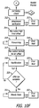
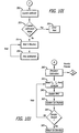
- FIGS. 10A-10K illustrate a method of operation performed by the controller in order to obtain one or more deep tissue temperature measurements.
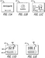
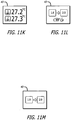
- Figures 11A-11M illustrate information output by the controller during execution of the method. The information is provided by way of the display panel 43, and each instance of information is referred to as a "screen" in the description that follows.
- Figure 10A is a state transition diagram that illustrates a sequence of machine states through which the zero-heat-flux DTT measurement system 40 transitions to obtain measurement of deep tissue temperature. Although a specific state sequence is shown, many other transitional states, operational steps, and fault conditions are possible during the operation to be described.
- a boot screen FIG. 11A
- STANDBY state 251 When fully booted up, the system 40 enters a STANDBY state 251, where it awaits the presence of a probe 44. At this time, a standby screen ( FIG. 11B ) is displayed.
- the system 40 When the system operator has plugged a probe 44 into the connector 48 of the signal interface cable 46, the system enters a READY state 252, indicated by a ready screen ( FIG. 11C ). Once a probe 44 is attached to a patient, the system 40 performs several sequential steps. First, the probe 44 is preheated by means of the heater 126 to somewhat above a transient skin temperature, which is not the core temperature, to accelerate equilibration. This operational condition, which may last for several minutes, is referred to as a PREWARMING state 253. Upon completion of prewarming, the system 40 attempts to cause equilibration between the skin thermistor 142 and the heater thermistor 140 using PID control.
- This operational condition which may take an additional 3-5 minutes, is referred to as the EQUILIBRATION state 254.
- an equilibration screen is displayed ( FIG. 11D or 11E ).
- the current temperature measured by the skin thermistor 142 is displayed, but is flashing and color-coded to show that the final temperature has not yet been reached.
- the screen also includes a progress bar 401, which shows approximate progress of the equilibration process.
- the screen indicates whether the measurement is in Celsius ( FIG. 11D ) or Fahrenheit ( FIG. 11E ).
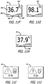
- the system 40 enters a normal STEADY state 255, indicated by a steady screen ( FIG. 11F or 11G ).
- the steady screen shows the current temperature of the skin thermistor 142, as well as whether the reading is in Celsius ( FIG. 11F ) or Fahrenheit ( FIG. 11G ).
- the steady screen shows a bar graph of patient temperature readings from the recent past. Preferably, but not necessarily, each bar comprises the average reading of a five minute interval and has sufficient space to show up to two hours of overall time.
- the patient temperature is referenced to a line indicating 36°C, a widely accepted threshold for hypothermia in humans.
- a first error state is a system error state, indicated by a system error screen ( FIG. 11I ).
- a second error state is a probe error state, indicated by a probe error screen ( FIG. 11I ).
- Either type of error state interrupts operation of the system. However, once system operation is interrupted, different resolution actions are indicated. In this regard, a probe error can be resolved by unplugging the probe; however a system error is usually not resolvable by the system operator. Any transition from one state to a succeeding one of the states 252, 253, 254, and 255 directs the program flow to stream F, which continues in FIG. 10E .
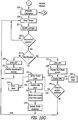
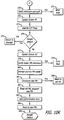
- FIGS 10B-10K illustrate a method by which the controller 200 operates the measurement system 42 to measure deep tissue temperature with the probe 44 connected to the system 40.
- These figures, and the accompanying explanation, presume appropriate programming of the MCU 202. Accordingly, unless otherwise indicated, the steps or acts that are illustrated and described are "controller-executed” steps, or are steps executed by a zero-heat-flux DTT measurement system.
- FIG. 10B illustrates a main control loop for the system 40.
- Figure 10C shows a probe connection sequence.
- Figure 10D shows a Celsius/Fahrenheit change sequence.
- Figure 10E shows a probe disconnection sequence.
- Figure 10F shows a heater control sequence.
- Figure 10G shows a data acquisition sequence.
- Figure 10H shows a safety check sequence.
- Figure 10I shows an EMU calibration sequence.
- Figure 10J shows a calibration dongle connection sequence.
- the MCU 202 can run the various process streams sequentially, or in an interlaced fashion, but at such a speed that they appear parallel from the point of view of the system operator.
- These process streams are a probe disconnection sequence (stream F, FIG. 10E ), a heater control sequence (stream H, FIG. 10F ), a main data acquisition sequence (stream I, FIG. 10G ), and a C/F change sequence (stream D, FIG. 10D ).
- the first step 261 begins when the processing and display unit 42 is plugged in and power is available.
- a control software program is initiated in the MCU 202.
- the boot screen ( FIG. 11A ) is output on the display panel 43 during the BOOT state 250.
- the standby screen ( FIG. 11B ) is displayed.
- the system is caused to enter the standby state 251 wherein it continuously attempts to confirm the presence of an EEPROM on a connected probe. If an EEPROM is detected, the switch 222 is placed in its second state and information is read from the EEPROM.
- the information includes at least probe authentication code and probe type data.
- a checksum on the EEPROM is examined for consistency. For example, copies of the authentication and type data can be written at multiple locations and provided to a checksum algorithm for validation of the stored data. If the checksum is invalid, an error 267 is generated.
- the authentication code read from the EEPROM is examined for consistency. If authentication is invalid, an error message 269 is generated.
- a probe type parameter read from the EEPROM is examined to determine which type of probe is present. If the probe type is unrecognized, an error 271 is generated. Preferably, one or more probe types are recognized; for example any one of three probe types can be present on a probe.
- a first type, found in step 272, is a normal disposable ZHF probe used for measuring patient DTT.
- a second probe type found in step 273, is a dongle, a device used to access restricted data or software for certain functions. For example, a calibration dongle configured to detachably connect to the signal interface cable connector 48 can be accessed by way of the signal interface cable. If this probe type is recognized, the program flow is directed to stream B, which continues in FIG. 10J .
- a third probe type, found in 274, is a firmware dongle used to access firmware of the system 40 for the purpose of upgrading, changing, or replacing programming. If this probe type is recognized, the program flow is directed to stream C, which continues in FIG. 10K .
- the following EEPROM memory map and pseudo-code sequence illustrate a routine executed by the controller for detecting connection of a DTT probe: DTT PROBE EEPROM MEMORY MAP Start Address Data A1 Serial Number A2 Authentication Key A3 Sensor Type: DTT Probe A4 Sensor Revision A5 Checksum A6 Uses Remaining A7 Time Remaining A8 Skin Thermistor bias A9 Skin Thermistor coefficient A A10 Skin Thermistor coefficient B A11 Skin Thermistor coefficient C A12 Heater Thermistor bias A13 Heater Thermistor coefficient A A14 Heater Thermistor coefficient B A15 Heater Thermistor coefficient C A16 Error A17 Trend data ... ...
- a sequence of connection steps is executed to prepare for operation when the probe is attached to a body for temperature monitoring.
- the integrity of the heater 126 is checked at step 280. Lack of electrical continuity in the heater circuit or inappropriate electrical resistance results in a probe error 281:
- the probe integrity is checked. Lack of electrical continuity in the thermistor circuits or inappropriate electrical resistance results in a probe error 283.
- a value of the probe revision is checked. In this regard, a probe revision parameter is used in case the data structure or the EEPROM changes, or other software-driven variants of the probe are desired. If the probe revision is not recognized, a probe error 285 is generated.
- the EEPROM contains parameters that are intended to limit extended use or reuse of the probe.
- a use count parameter in the Uses Remaining field in the DTT Probe EEPROM Memory Map
- a use count on the EEPROM is checked, and if it is equal to zero, system operation is interrupted and a probe error 287 is generated.
- a use time parameter in the Time Remaining field in the DTT Probe EEPROM Memory Map
- the EEPROM is periodically updated with new information (e.g., patient temperature).
- the current use time on the EEPROM is incremented downward by an appropriate time interval. If the check performed in step 288 finds that the use time is zero, a probe error 289 is generated.
- a serial number parameter implements measures to ensure that direct copies of the same probe (i.e., "direct knock offs") are detected. In this regard, a list of the most recent probe serial numbers used is maintained in nonvolatile memory of the MCU 202. If step 290 finds that particular probe has been used more than an allowed number of times, an error 291 is generated.
- step 293 the system 40 enters the READY state 252, the ready screen of FIG. 11C is displayed, and PID control of the heater 126 commences.
- the screen instructs the user to attach the probe to the patient.
- attachment can be indicated by the divergence of the two temperature sensors over time (i.e. current
- a preferred mode is to check that the skin temperature, as measured by thermistor 142, is above a threshold temperature (for example, 35°C) and that a time-wise slope of skin temperature change is greater than a threshold value; for example, 1.5°C/5 seconds.
- the system remains in the READY state, step 294, until these conditions are fulfilled.
- the system spawns parallel stream H ( FIG. 10F ) in step 295, spawns parallel stream I ( FIG. 10G ) in step 296, and spawns parallel stream D ( FIG. 10D ) in step 297.
- Process stream D ( FIG. 10D ) monitors the C/F button 59 and changes Celsius to Fahrenheit or vice versa.
- Step 300 checks for a button-press event. If the current mode is Celsius, step 302 changes it to Fahrenheit. If the current mode is Fahrenheit, step 301 changes it to Celsius.
- step 305 the system determines whether continuity with the EEPROM has been interrupted by attempting to read from it. If signal continuity between the controller 200 and the probe has not been interrupted, the read is successful, and the system transitions to the succeeding state. If the read fails, the probe has been disconnected from the connector, and a series of steps are taken to return the system to the standby state 265.
- step 306 PID control of the heater is deactivated.
- step 307 data acquisition from the thermistors is discontinued.
- step 308 the external circuit to the EMU subsystem is deactivated. Then step 309 returns software control to step 265.
- step 310 a parallel process stream E is initiated to monitor the probe 44 for unsafe thermal conditions, while the controller continues to regulate operation of the heater 126 through the PID control method initiated in step 293.
- step 312 the controller checks whether the probe is still attached to the patient using methods described above for step 294. If the software detects numerical instability in the control loop, a probe error 313 results.
- step 314 the allowable heater maximum output is increased to 90%.
- step 315 the controller causes the system to enter the prewarming state (state 253 in FIG. 10A ) and display the equilibration screen ( FIG. 11D or 11E ) on the display panel 43. An error in this state results in a probe error 316.
- a family of curves representing the decaying offset term is illustrated in FIG. 13 .
- the effect of the decaying offset term is to set a target heater temperature above the transient skin temperature by an initial offset amount known as the initial error term offset ( ⁇ n ).
- the offset is allowed to decay throughout the prewarming period for a duration (t n ) so that at the end of prewarming there is a smooth transition to normal PID heater control.
- step 3151 the controller determines initial prewarming parameters (initial error term offset ( ⁇ n ) and prewarming duration (t n )) preferably based on the current condition of the probe.
- One probe condition that can be used to generate these terms is a time-wise rate of change (slope) sensed by the skin thermistor 142. For example, if the slope of thermistor 142 is large (for example, greater than 3.6°C/minute), the probe is far from being equilibrated to the patient's DTT temperature and maximum prewarming is required.
- ⁇ n is set to 3°C ( ⁇ 1 in FIG. 12 ) and t n would be set to 300 seconds (t 1 in FIG.12 ).
- the initial error term offset ⁇ n is set to 1.5 °C ( ⁇ 2 in FIG. 13 ) and t n is set to 150 seconds (t 2 in FIG.12 ).
- the slope of thermistor 142 is low (for example, 0.24 °C/minute), possibly indicating a probe that was recently equilibrated became temporarily detached from the patient, no prewarming is needed and both ⁇ n and t n are set to zero.
- step 3152 the duration since the prewarming initiation (t) is calculated.
- step 3153 the duration calculated in step 3152 is compared to the prewarming duration (t n ) calculated in step 3151. If t is greater than or equal to t n , prewarming is completed and process continues to step 317 of FIG. 10F . If t is less than t n , the process continues to step 3154 where the updated offset term ( ⁇ o (t)) is calculated.
- step 3155 a new error value ⁇ is calculated by combining the error value ⁇ (i) with the offset ⁇ o (t). This error value is used in the PID control of the heater 126. Although a linear function relating ⁇ o (t) to t is used, this is not intended to limit the prewarming step 315; in fact, other functions could be used.
- the controller checks again for unusually high heater output in step 317. Then, in step 318, the controller causes the system to enter the equilibration state (254 in FIG. 10A ), whereby PID control is applied to the heater 126 to attempt to bring the probe into a ZHF condition. An error in this state results in a probe error message 319. If ZHF is achieved, the controller checks for calibration of the EMU 227 in step 320. If the EMU is not calibrated, control returns to step 318. If EMU calibration is complete, the controller sends the system into a steady-state condition 321 where the emulator resistance is accessible to a connected patient monitor and the PID control is operated to maintain the ZHF condition. Any fault in this state results in a probe error message 322.
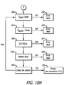
- the controller initiates and maintains a main data acquisition sequence.
- the controller initiates calibration of the EMU 227 by way of the process stream G ( FIG. 10I ).
- the controller determines the heater and skin temperatures (T h and T s ) sensed by the heater thermistor 140 and the skin thermistor 142.
- thermistor data obtained via the ADC 224 are in units of electrical voltage, which is converted to resistance and then to temperature.
- the resistance values are converted to temperature by applying the Steinhart-Hart coefficients stored on the EEPROM 170. Once converted, running averages of T h and T s are updated in step 327.
- the acquisition of the temperature data points can be much faster, but preferably, is performed once per second (1Hz); accordingly, after each set of data points is obtained, data acquisition continues in step 328, and the current setoff data points is checked in step 329 to see if criteria for entering the equilibration state are met.
- the time-wise slope of the T h and T s temperature curves change very slowly as equilibration is approached, and sources of small instrumental error can cause the system to bounce into and out of the zero-heat-flux condition.
- it is not necessary to achieve an absolute absence of heat flux as long as the differences are within acceptable limits for accuracy.
- a probe is considered to have achieved a zero-heat-flux condition if: 1) the difference between T h and T s is less than a first threshold value (for example, 0.1°C), and 2) the time-wise slope of T s is less than a second threshold value (for example, 0.06°C/minute).
- a first threshold value for example, 0.1°C
- a second threshold value for example, 0.06°C/minute
- the controller in step 337, causes the EMU system 227 to close the switch 234 to output signal jack 54 so as to provide the external patient monitor 56 with access to a resistance value equivalent to the patient temperature data. Then, in step 338, the controller initiates output of a steady screen ( FIG. 11F or 11G ) on the display panel 43 during the STEADY state 255 ( FIG. 10A ). At this time, in step 339, the controller conveys any changes in patient temperature to the EMU 227. Any fault in EMU operation causes a system error 340.
- step 341 the controller determines if the time interval has elapsed. If not, another set of data points is acquired (step 326). Otherwise, the running average of patient temperature is written to the EEPROM (step 332), with a write-error resulting in a probe error message (step 333). Next, the use time value on the EEPROM is updated, reflecting the time interval used in step 341. If the probe 44 has been plugged in for a time less than the time interval (i.e., the first time this step has occurred during the current use), the use count parameter read from the EEPROM is decremented by one (step 335) and the decremented use count is written to the EEPROM.
- the use count is decremented only once each time a probe is plugged in, and then only if a main data acquisition sequence has been initiated and the system has reached equilibrium (step 329) with no update error (step 340) and no trend write error (step 333). Stated another way, the use count is checked once ( FIG. 10C , steps 286 and 288) and, if the use count has not reached a blocking value (zero in this example) during a previous connection sequence, it is decremented once during the current probe connection sequence. Finally, the list of used probe serial numbers in MCU memory is updated (step 336). Then, another set of data points is acquired (step 326).
- step 329 the controller determines that the probe 44 does not meet the criteria for equilibration, the EMU 227 is turned off (330), and, in step 331, the system remains in the EQUILIBRATION state 254 ( FIG. 10A ), showing the equilibration screen ( FIG. 11D or 11E ) on display 43.
- the controller performs an ongoing check for fault conditions in the probe 44.
- the controller checks skin temperature T s for values above an unsafe threshold, for example 43°C, with a fault resulting in a probe error 343.
- the controller makes a similar check of heater temperature T h , with a fault resulting in a probe error 345.
- the controller compares the magnitude of the difference between T s and T h with a threshold value (for example 10°C), to ensure that the two thermistor values are consistent with each other.
- a threshold value for example 10°C
- a simple and effective heater safety circuit observes the heater operational parameters: a level of current through the heater, and a time that the heater remains on during any pulse of the PWM signal.
- a current level higher than a predetermined safety level (700 mA, for example) indicates a possible short circuit condition in the heater.
- a pulse width longer than a predetermined time (2 seconds, for example) indicates a possible fault that causes the heater switch 216 to stay on too long (which will overdrive the heater).
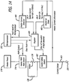
- a preferred heater safety circuit for a PWM heater control mode is illustrated in FIG. 13 .
- the heater safety circuit includes a heater current detector 400, a heater-on timer 402, a register 405 of the MCU 202, a current sense resister 403, and a heater safety switch 407.
- the elements of the heater safety circuit are located in the controller 200.
- the heater 126 is located on a probe 44. With the heater switch 216 closed a pulse of current is drawn by the heater 126.
- the current magnitude is sensed by the resistor 403 and the resulting voltage is input to both the current detector 400 and the timer 402.
- the current detector 400 monitors the level of the input voltage. When the current pulses on, the timer 402 begins a count down.
- the current detector 400 If the magnitude of the current exceeds the safety level, the current detector 400 generates a fault indication that is stored in the register 405. If the timer 402 does not count out before the pulse falls, it is reset to zero and starts another count from zero with the next pulse. If the timer counts out before the pulse falls to zero, it generates a fault indication that is stored in the register 405. A fault indication in the register 405 is reported to the MCU 202 and at the same time causes the heater safety switch 407 to open, which halts current flow to the heater 126. When a heater safety fault occurs, the MCU 202 writes an error code to the probe, which marks the probe as faulty and prevents it from being used again. The MCU 202 then erases the fault from the register, thereby closing the safety switch 407
- step 350 the controller applies criteria for detachment of the probe from a patient.
- skin temperature falls below 30°C and skin temperature is below heater temperature by a predetermined value (for example, 1.0°C); or the slope of the skin temperature is ⁇ -625 m°C/5seconds. If either condition is met, the controller, in step 351, returns the system to the READY state 252 ( FIG. 10A ).
- process stream G the operation of the EMU 227 is initiated and maintained.
- the EMU periodically self-calibrates in order to provide an output that accurately emulates patient temperature in YSI-400 format.
- calibration is actually performed in two stages: coarse and fine.
- Coarse calibration can be a relatively lengthy process (e.g., several minutes), therefore it is performed during the EQUILIBRATION state 254 ( FIG. 10A ) so as not to delay the output of patient temperature. If coarse calibration fails (step 353), a system error 354 occurs. If coarse calibration is successful, in step 355 the controller causes a delay of some interval, for example, five minutes, after which a fine calibration of the EMU occurs (step 356). Fine calibration is a shorter process than coarse calibration, for example, requiring less than one second to complete.
- a calibration dongle is used to check the calibration of the zero-heat-flux DTT measurement system 40 (process stream B) and to initiate calibration of the emulation system (process stream G).
- the controller enables a system operator to check the calibration of the system with a calibration dongle.
- This dongle resembles a probe, in that it connects to the patient cable and has an EEPROM for storage of S-H coefficients.
- the dongle differs from a probe by having precision resistors rather than thermistors. The resistance values of these resistors are chosen to provide a standard output that can be read on the display panel 43 and the patient monitor 56. By this process, a complete verification of system function and accuracy is provided.
- step 360 the controller initiates calibration of the EMU 227 by way of the parallel process stream G ( FIG. 10I ).
- the controller determines temperatures of the skin thermistor T s and heater thermistor T h in step 361.
- thermistor data obtained via the ADC 224 are in units of ADC counts, which are converted into units of resistance (ohms).
- the resistance values are converted to temperature by applying the Steinhart-Hart coefficients stored on the dongle's EEPROM.
- step 362 the controller updates the EMU 227 with the current value of T s .
- the controller outputs a calibration screen ( FIG. 11K ), with display continuing until the dongle is detached.
- a dongle is used to update programming of the zero-heat-flux DTT measurement system 40.
- Process stream C ( FIG. 10K ) enables a system operator to update the firmware of the controller 200 by means of a firmware update dongle.
- This dongle resembles a normal probe, in that is connects to the connector 48 of the patient cable 46 and has an EEPROM; however it has no heater or thermistors.
- step 370 verifies a checksum of the contents of the EEPROM, resulting in an error 371 if incorrect.
- step 372 causes update screen #1 ( FIG. 11L ) to be displayed.
- the user confirms the update by pressing the C/F button 59.
- step 377 changes the display panel 43 to update screen #2 ( FIG. 11M ).
- step 378 verifies a loader checksum, with a fault resulting in a probe error 379.
- Step 380 decrypts the updated software from the dongle's EEPROM and runs the firmware update code.
- step 381 the system verifies the checksum. If the checksum is incorrect, the system reverts to previous version of the firmware, step 588.
- Step 382 performs cleanup by erasing the old version of the firmware from memory, followed by rewriting of the system's authentication keys, 383. Finally, step 384 causes the DTT measurement system to reset to the new firmware, following which, the firmware update dongle is detached, step 385.
- FIG. 15 illustrates a dongle construction that can be used for calibration and programming.
- the dongle 1500 is shown in plan, with the view directed toward a dongle surface 1501 on which electronic components are mounted.
- components are mounted to one surface of a rigid circuit board configured with a tab 1508 that can be physically, realeasably, and electrically connected to the patient sensor cable 46 in the same manner as a DTT probe.
- the dongle is constructed to accommodate an 8-pin SOIC (small-outline integrated circuit) EEPROM 1510 along with five surface mounted resistors R1-R5.
- SOIC small-outline integrated circuit
- the calibration dongle preferably requires high precision (.1%) resistors whose resistance matches closely with that of a 10K ⁇ thermistor near 36°C.
- the programming dongle only requires a low precision pull-up resistor whose resistance is 10k ⁇ .
- the position of the resistors on the PCB allows the circuit to be visually identified. That is, if surface mounted resistors are placed in positions R1 and R3, the dongle can be identified programming dongle.
- a low precision 6.2 ⁇ resistor can, optionally, populate position R5. This position allows the heater circuitry to be checked.
Description
- This application contains subject matter related to subject matter of the following US patent applications:
-
US patent application 12/584,108, filed 08/31/2009 -
US patent application 12/798,668, filed 04/07/2010 -
US patent application 12/798,670, filed 04/07/2010 -
US provisional application for patent 61/463,393, filed 02/16/2011 - The subject matter relates to a system for measurement of deep tissue temperature (DTT) as an indication of the core body temperature of humans or animals. More particularly, the subject matter relates to constructions and operations of a zero-heat-flux DTT measurement system with a cable interface for connection to a disposable DTT probe.
- Deep tissue temperature is a proxy measure for core temperature, which is the mass-weighted mean temperature of the body contents. It is desirable to maintain core body temperature in a normothermic range in many clinical situations. For example, during the perioperative cycle maintenance of normothermia has been shown to reduce the incidence of many adverse consequences of anesthesia and surgery, including surgical site infections and bleeding; accordingly, it is beneficial to monitor a patient's body core temperature before, during, and after surgery. Of course noninvasive measurement is highly desirable, for the safety and the comfort of a patient, and for the convenience of the clinician. Thus, it is most advantageous to obtain a noninvasive DTT measurement by way of a device placed on the skin.
- Noninvasive measurement of DTT by means of a zero-heat-flux device was described by Fox and Solman in 1971 (Fox RH, Solman AJ. A new technique for monitoring the deep body temperature in man from the intact skin surface. J. Physiol. Jan 1971:212(2): pp 8-10). Because the measurement depends on the absence of heat flux through the skin area where measurement takes place, the technique is referred to as a "zero-heat-flux" (ZHF) temperature measurement. The Fox/Solman system, illustrated in
FIG. 1 , estimates core body temperature using a ZHFtemperature measurement device 10 including a pair ofthermistors 20 separated bylayer 22 of thermal insulation. A difference in the temperatures sensed by thethermistors 20 controls operation of aheater 24 of essentially planar construction that stops or blocks heat flow through a skin surface area contacted by thelower surface 26 of thedevice 10. Acomparator 29 measures the difference in the sensed temperatures and provides the difference measurement to acontroller 30. Theheater 24 is operated for so long as the difference is non-zero. When the difference between the sensed temperatures reaches zero, the zero heat flux condition is satisfied, and theheater 24 is operated as needed to maintain the condition. Thethermistor 20 at thelower surface 26 senses a temperature near, if not equal to, that of the skin surface area and its output is amplified at 36 and provided at 38 as the system output. Togawa improved the Fox/Solman measurement technique with a DTT measurement device structure that accounted for multidimensional heat flow in tissue. (Togawa T. Non-Invasive Deep Body Temperature Measurement. In: Rolfe P (ed) Non-Invasive Physiological Measurements. Vol. 1. 1979. Academic Press, London, pp. 261-277). The Togawa device encloses a Fox and Solman-type ZHF design in a thick aluminum housing with a cylindrical annulus construction that reduces or eliminates radial heat flow from the center to the periphery of the device. - The Fox/Solman and Togawa devices utilize heat flux normal to the body to control the operation of a heater that blocks heat flow from the skin through a thermal resistance in order to achieve a desired zero heat flux condition. This results in a construction that stacks the heater, thermal resistance, and thermal sensors of a ZHF temperature measurement device, which can result in a substantial vertical profile. The thermal mass added by Togawa's cover improves the stability of the Fox/Solman design and makes the measurement of deep tissue temperature more accurate. In this regard, since the goal is to achieve zero heat flux through the device, the more thermal resistance the better. However, the additional thermal resistance adds mass and size, and also increases the time required to reach a stable temperature.
- The size, mass, and cost of the Fox/Solman and Togawa devices do not promote disposability. Consequently, they must be sanitized after use, which exposes them to wear and tear and undetectable damage. The devices must also be stored for reuse. As a result, use of these devices raises the costs associated with zero-heat-flux DTT measurement and can pose a significant risk of cross contamination between patients. It is thus desirable to reduce the size and mass of a zero-heat-flux DTT measurement device, without compromising its performance, in order to promote disposability.
- Inexpensive, disposable, zero-heat-flux DTT measurement devices are described and illustrated in the related US patent applications ("the related applications") and in
US2011/051776 A1 ,US2009/116536 A1 ,US5483190 A1 ,WO2010/103436 A1 ,US5735605 A . A measurement device constructed according to the related applications is attached to the skin of a human or animal subject to sense the temperature of tissue deep under the skin. The measurement device is constituted of a flexible substrate and an electrical circuit disposed on a surface of the flexible substrate. The electrical circuit includes an essentially planar heater which is defined by an electrically conductive copper trace and which surrounds an unheated zone of the surface, a first thermal sensor disposed in the zone, a second thermal sensor disposed outside of the heater trace, a plurality of contact pads disposed outside of the heater trace, and a plurality of conductive traces that connect the first and second thermal sensors and the heater trace with the plurality of contact pads. Sections of the flexible substrate are folded together to place the first and second thermal sensors in proximity to each other. A layer of insulation disposed between the sections separates the first and second thermal sensors. The measurement device is oriented for operation so as to position the heater and the first thermal sensor on one side of the layer of insulation and the second thermal sensor on the other and in close proximity to an area of skin where a measurement is to be taken. The layout of the electrical circuit on a surface of the flexible substrate provides a low-profile, zero-heat-flux DTT measurement device that is essentially planar, even when the sections are folded together. Such devices are referred to as "sensors" or "probes". In the following specification such a device will be referred to as a "probe" in order to avoid ambiguity with respect to the term "thermal sensor", which is used in the specification to denote a device having an electrical property that changes in response to a change in temperature. - Given the advances in construction and performance of lightweight, disposable probes as is evidenced in the related applications, it is now desirable to establish system mechanizations and procedures that quickly produce accurate and reliable temperature measurements in response to sensed data produced by such probes. In particular, there is a need for a zero-heat-flux deep tissue temperature (DTT) measurement system that measures internal body temperature by way of a lightweight, disposable measurement probe that includes a heater and thermal sensors disposed in a zero-heat-flux construction.
- Further, such a measurement system can have a construction customized for stand-alone operation. That is to say, one that does not include a standard signal output that can be accepted as an input by multi-function patient monitors. However, it is desirable that such an output signal interface conforming to a standard device or a standard input signal configuration defined for multi-function patient monitors would increase the versatility and usefulness of such a zero-heat-flux DTT measurement system.
- In one aspect, the disclosure concerns a zero-heat-flux DTT measurement system with a simple, low cost interface suitable for being used with disposable probes.
- In another aspect, the disclosure concerns simple, effective, and inexpensive system control mechanization for lightweight probes with low thermal mass.
- In yet another aspect, the disclosure concerns a zero-heat-flux DTT measurement system with a simple, low cost output signal interface conforming to a standard input signal configuration for multi-function patient monitors.
- These and other aspects are embodied in a zero-heat-flux DTT measurement system with a signal interface where a probe can be connected to and disconnected from the system.
- A programmable memory for storing system information including thermal sensor calibration coefficients is located on the probe together with a heater and thermal sensors.
- These and other aspects are embodied in a zero-heat-flux, DTT measurement system implementing control mechanization that checks signal continuity between the system and a probe, validates probe operation, determines skin and heater temperatures, and executes a control loop with safety measures related to measured skin and heater temperatures.
- These and other aspects are embodied in a zero-heat-flux, DTT measurement system including an output signal interface conforming to a standard input signal configuration for multi-function patient monitor.
- In another aspect, the disclosure concerns a signal interface conforming to a standard device or a standard input signal configuration.
- This and other aspects are embodied in a system and method for emulating a standard thermistor output signal indicative of deep tissue temperature.
-
-
FIG.1 is a schematic block diagram of a prior art deep tissue temperature measurement system including a zero-heat-flux DTT measurement probe. -
FIG. 2 is an illustration of a zero-heat-flux DTT measurement system embodying solutions to the problems described above. The illustration shows connections made between a processing and display unit and a probe. -
FIG. 3 is an illustration of the zero-heat-flux DTT measurement system ofFIG. 2 showing the connections made between the processing and display unit and a patient monitor with a standard interface. -
FIG. 4 is a first side sectional, partly schematic illustration of a zero-heat-flux DTT measurement probe illustrating components of a multi-layer construction. -
FIG. 5 is a second side sectional, partly schematic illustration of the probe ofFIG. 4 rotated to illustrate a programmable memory device included in the multi-layer construction. -
FIG. 6 illustrates a construction for assembling a zero-heat-flux DTT measurement probe. -
FIG. 7 is an electrical schematic diagram including elements of the probe construction ofFIG. 6 . -
FIG. 8 is a block diagram illustrating elements of the zero-heat-flux DTT measurement system ofFIG. 2 . -
FIG. 9 is a partial electronic schematic diagram illustrating an emulator for generating an output signal conforming to a standard input signal configuration for a patient monitor. -
FIG. 10A is a state diagram illustrating machine states of the zero-heat-flux, DTT measurement system ofFIG. 2 . -
FIGS 10B-10K together form a flow diagram illustrating a method by which the zero-heat-flux, DTT measurement system ofFIG. 2 is operated. -
FIGS. 11A-11M illustrate information screens generated during the operation of the zero-heat-flux, DTT measurement system ofFIG. 2 . -
FIG. 12 is a flow diagram illustrating a preferred process for prewarming a DTT measurement probe. -
FIG. 13 is a family of curves illustrating an error bias function used in the preferred process ofFIG.12 . -
FIG. 14 is a block diagram of a preferred heater safety circuit of the zero-heat-flux DTT measurement system ofFIG. 2 . -
FIG. 15 is a plan view of a representative dongle construction used for calibration and/or programming the zero-heat-flux DTT measurement system ofFIG. 2 . - A zero-heat-flux deep tissue temperature (DTT) measurement system measures internal body temperature by way of a zero-heat-flux DTT measurement probe that includes a heater and thermal sensors in a zero-heat-flux construction. The measurement system includes a processing and display unit with control mechanization that checks signal continuity with the probe, authenticates probe identity, decrements a use count of the probe, determines heater and skin temperatures based upon information obtained from the probe, and calculates a deep tissue temperature. The control loop implements safety measures related to measured temperatures and security measures related to integrity of data and probe use information associated with the probe. The measurement system includes a signal interface cable with an attached connector by which a probe can be physically, releasably, and electrically coupled to the system. The cable and connector together constitute a single element that is a removable and replaceable part of the system, separate from the probe. A standard output signal indicative of deep tissue temperature is provided by a measurement system emulation unit that imitates operation of a thermal sensor device.
- A zero-heat-flux DTT measurement probe (hereinafter, simply "a probe") includes at least two thermal sensors, a heater, and a programmable memory device. For example, a construction for such a probe includes a flexible substrate with at least two thermal sensors disposed thereon in a spaced-apart relationship. Preferably the thermal sensors are maintained in a spaced apart relationship on respective substrate layers by a flexible thermal insulator positioned between the layers. The substrate supports at least the thermal sensors, the separating thermal insulator; the programmable memory device, and the heater. The probe construction includes a periphery with a tab by which the probe is removeably coupled with a probe signal interface cable connector.
- As per
FIG. 2 , a zero-heat-fluxDTT measurement system 40 includes a processing and display unit 42 (hereinafter, "controller") and aprobe 44. Asignal interface cable 46 has first and second ends and aconnector 48 mounted to the first end where a probe such as theprobe 44 can be physically, removeably, and electrically coupled to the system. Thesignal interface cable 46 has aconnector 50 mounted to the second end which can be inserted into and removed from asignal connector jack 52 in thecontroller 42. Thesignal interface cable 46 andconnectors probe 44, and that are not formed together with the probe. In some aspects, adongle 45 can be connected to and removed from the system by way of thesignal interface cable 46, withconnectors FIG. 3 , thecontroller 42 has anoutput signal jack 54 where acable 55 can be removeably plugged to conduct an output signal produced by an emulation unit to clinical equipment such as a multi-function patient monitor 56. The output signal is indicative of deep tissue temperature measured by thesystem 40 and conforms to a signal produced by an emulated temperature-responsive device. A manually-operated C/F button 59 on the rear surface of thecontroller 42 allows a system operator to select a scale (Celsius or Fahrenheit) for indicating temperature. - As seen in
FIG. 2 , thecontroller 42 includes information display elements by which measured temperatures, status indications, prompts, alarms and other system information are provided in visible form to a system operator. For example, amulti-function display panel 43 of the liquid crystal type (LCD) displays a measured temperature. - Zero-heat-flux DTT measurement probes that can be used in the zero-heat-flux DTT measurement system are preferably, but not necessarily, constructed according to the related applications. An example of a disposable probe representative of the
probe 44 inFIG. 2 is shown inFIGS. 4-6 . As per these figures, a zero-heat-flux DTT measurement probe includes a flexible substrate supporting an electrical circuit in which a heater trace disposed on a first substrate layer defines a heater facing one side of a layer of thermally insulating material and surrounding a zone of the first substrate layer. A first thermal sensor is disposed in the zone, a programmable memory device is disposed on the first substrate layer outside of the heater, a second thermal sensor is disposed on the second substrate layer, a plurality of contact pads is disposed outside of the heater trace on a substrate surface, and a plurality of conductive traces connect the heater trace, the first and second thermal sensors and the programmable memory device to the contact pads. -
FIG. 4 is a sectional, partially-schematic illustration of a preferred probe construction.FIG. 5 is a sectional, partially-schematic illustration of the preferred probe construction in which the section is rotated from the view ofFIG. 4 . As perFIG. 4 , theprobe 44 includes flexible substrate layers, a layer of thermally insulating material, and an electrical circuit. The electrical circuit includes aheater 126, a firstthermal sensor 140, and a secondthermal sensor 142. Theheater 126 and the firstthermal sensor 140 are disposed in or on aflexible substrate layer 103 and the secondthermal sensor 142 is disposed in or on aflexible substrate layer 104. The first and second substrate layers 103 and 104 are separated by aflexible layer 102 of thermally insulating material. Theflexible substrate layers layer 102. A layer ofadhesive material 105 mounted to one side of thesubstrate layer 104 is provided with a removable liner (not shown) to attach the probe to skin. Preferably, aflexible layer 109 of insulating material lies over thelayers substrate layer 103. The insulatinglayer 109 extends over theheater 126 and the firstthermal sensor 140. - As seen in
FIG. 5 , the electrical circuit further includes aprogrammable memory device 170 andcontact pads 171 disposed in or on theflexible substrate layer 103. Theprogrammable memory device 170 is positioned outside of theheater 126, preferably between theheater 126 and thecontact pads 171. Thecontact pads 171 are positioned on asection 108 of thesubstrate layer 103 that projects beyond the insulatinglayer 109 so as to be detachably coupled with theconnector 48 fixed to the first end of thecable 46. As will be explained in detail with reference to other figures, theprogrammable memory device 170 stores authentication data, thermal sensor calibration values, measured temperature data, probe use data, and other information. Presuming that thethermal sensors programmable memory device 170 on theprobe 44, between theheater 126 and thecontact pads 171 permanently associates stored thermal sensor calibration information with theprobe 44. Consequently, the need for a cable, with connector, permanently attached to the probe is eliminated. Moreover, since thecable 46 andconnector 48 do not store unique calibration information, they can be used for any zero-heat-flux DTT measurement probe configured in accordance with the related applications. - With reference to
FIGS. 4 and5 , theprobe 44 is disposed on a human or animal subject with the secondthermal sensor 142 nearest the skin. Thelayer 102 is sandwiched between the first and second substrate layers 103 and 104 so as to separate theheater 126 and firstthermal sensor 140 from the secondthermal sensor 142. In operation, thelayer 102 acts as a thermal resistance between the first and second thermal sensors, the secondthermal sensor 142, located on the surface of thelayer 102 that is closest to the skin, senses the temperature of the skin, and the firstthermal sensor 140 senses the temperature at the opposing surface of thelayer 102 away from the body. While the temperature sensed by the firstthermal sensor 140 is less than the temperature sensed by the secondthermal sensor 142, the heater is operated to reduce heat flow through thelayer 102 and the skin. When the temperature difference across thelayer 102 is zero, heat flow through thelayer 102 has been stopped. This is the zero-heat-flux condition as it is sensed by the first andsecond sensors heater 126 is regulated as needed to maintain the condition. Preferably, but without limitation, the heater is regulated by changing the duty cycle of a square wave. - With reference to
FIG. 6 , a preferred construction of the substrate and electrical circuit portions of theprobe 44 includes aflexible substrate 101 withcontiguous sections section 105 is substantially circular in shape. The second section (or "tail") 106 has the shape of a narrow, elongated rectangle with abulbous end 107 that extends outwardly from the periphery of thecenter section 105 in a first direction. The third section (or "tab") is theextended section 108 seen inFIG. 5 . Thetab 108 has the shape of a wide rectangle that extends outwardly from the periphery of thecenter section 105 in a second direction. Opposingnotches 110 are formed in thetab 108 to receive and retain respective spring-loaded retainers of theconnector 48. Preferably, thetail 106 is displaced from thetab 108 by an arcuate distance of less than 180° in either a clockwise or a counterclockwise direction. - As per
FIG. 6 , anelectrical circuit 120 is disposed on theflexible substrate 101. Preferably, but not necessarily, the elements of theelectrical circuit 120 are located on thesurface 121 of theflexible substrate 101. Theelectrical circuit 120 includes at least an electrically conductive heater trace, thermal sensors, a programmable memory device, electrically conductive connective trace portions, and mounting and contact pads. Theheater trace 124 defines a generallyannular heater 126 surrounding azone 130 of thesubstrate 101 into which no portion of theheater trace 124 extends; in this regard, thezone 130 is not directly heated when the heater operates. Thezone 130 occupies a generally circular portion of thesurface 121. More completely, thezone 130 is a cylindrical section of thesubstrate 101 which includes the portion of thesurface 121 seen inFIG. 6 , the counterpart portion of the opposing surface (not seen in this figure), and the solid portion therebetween. Preferably, but not necessarily, thezone 130 is centered in thecenter section 105 and is concentric with theheater 126. The firstthermal sensor 140 is mounted on mounting pads formed in thezone 130. The secondthermal sensor 142 is mounted on mounting pads disposed outside of the generallyannular heater 126; preferably, these mounting pads are formed generally near the end of thetail 106, for example, in or near the center of thebulbous end 107 of the tail. In some constructions theprogrammable memory device 170 includes at least one multi-pin electronic circuit device mounted on theprobe 44. For example theprogrammable memory device 170 can be constituted of an electrically-erasable programmable read/write memory (EEPROM) mounted on mounting pads formed on a portion of thesurface 121 on thecenter section 105 near or adjacent thetab 108. Thecontact pads 171 are formed on thesurface 121, in thetab 108. A plurality of conductive trace portions connects the first and second thermal sensors, theprogrammable memory device 170, and theheater trace 124 with a plurality of thecontact pads 171. Preferably, but not necessarily, at least onecontact pad 171 is shared by theprogrammable memory device 170 and one of theheater 126, the firstthermal sensor 140, and the secondthermal sensor 142. - As seen in
FIG. 6 , preferably, but not necessarily, thecenter section 105 has formed therein a plurality ofslits center section 105. The slits define zones which move or flex independently of each other. The layout of theheater trace 124 is adapted to accommodate the slits. In this regard, the heater trace follows a zigzag or switchback pattern with legs that increase in length from the periphery of thezone 130 to the ends of the longer slits 151 and then, after a step decrease at those ends, generally increase in length again to the outer periphery of theheater 126 in the zones defined by the slits. As illustrated, the construction of the heater has a generally annular shape centered in thezone 130, although the annularity is interrupted by the slits. Alternatively, the annular shape can be viewed as including a peripheral annulus of wedge-shaped heater zones surrounding a generally continuous central annulus. - Preferably, but not necessarily, the
heater 126 has a non-uniform power density construction that can be understood with reference toFIG. 6 . In this construction, theheater 126 includes a central portion 128 (indicated by lightly drawn lines) having a first power density and a peripheral portion 129 (indicated by heavily drawn lines) which surrounds thecentral portion 128 and has a second power density higher than the first power density. Theheater trace 124 is continuous and includes two ends, a first of which transitions to contactpad 5, and the second to contactpad 6. However, because of the slits, each of the central andperipheral portions central portion 128 alternate with the sections of the peripheral portion. Nevertheless, the annular structure of the heater arrays the sections of thecentral portion 128 generally in a central annulus around thezone 130, and arrays the sections of theperipheral portion 129 around thecentral portion 128. When theheater 126 is operated, thecentral portion 128 produces a central annulus of heat at the first power density surrounding thezone 130 and theperipheral portion 129 produces a ringshaped annulus of heat at the second power density that surrounds the central annulus of heat. - The differing power densities of the
heater portions heater trace 124 and/or the pitch (distance) between the legs of a switchback pattern. For example, the resistance, and therefore the power generated by the heater trace, varies inversely with the width of the trace. For any resistance, the power generated by the heater trace also varies inversely with the pitch of (distance between) the switchback legs. - The
electrical circuit 120 on theflexible substrate 101 seen inFIG. 6 is shown in schematic form inFIG. 7 . Thecontact pads 171 on thetab 108 numbered 1-6 inFIG. 6 correspond to the identically-numbered elements inFIG. 7 . The number of contact pads shown is merely for illustration. More, or fewer, contact pads can be used; any specific number is determined by design choices including the specific device configuration of the programmable memory device, the heater construction, the number of thermal sensors, and so on. In some constructions it is desirable to utilize one or more of the contact pads for electrical signal conduction to or from more than a single element of theelectrical circuit 120 in order to minimize the number of contact pads, thereby simplifying the circuit layout, minimizing the size and mass of thetab 108, and reducing interface connector size. - Preferably, the
programmable memory device 170 includes a multi-pin EEPROM mounted by mounting pads to theprobe 44.FIGS. 6 and7 illustrate a construction in which one or more contact pads are shared by at least two elements of the electrical circuit. In this regard: - one lead of the second thermal sensor 142 (TH2) and
pin 1 of theprogrammable memory device 170 are connected by conductive trace portions to contactpad 1; - leads of the first and second thermal sensors 140,142 and
pin 4 of theprogrammable memory device 170 are connected by conductive trace portions to contactpad 2; - one lead of the first thermal sensor 140 (TH1) and
pin 3 of theprogrammable memory device 170 are connected by conductive trace portions to contactpad 3; -
pins programmable memory device 170 are connected by a conductive trace portion to contactpad 4; - the return end of the
heater trace 124 is connected by a conductive trace portion to contactpad 5; and - the input end of the
heater trace 124 is connected by a conductive trace portion to contactpad 6. - With reference to
FIGS. 4-6 , when theprobe 44 is assembled, thecenter section 105 andtail 106 are folded together about a flexible layer of insulating material such as thelayer 102. Thelayer 102 provides thermal resistance and electrical insulation between the thermal sensors; it also supports the thermal sensors in a spaced-apart configuration. In other words, the first and secondthermal sensors - The
probe 44, with theelectrical circuit 120 laid out on one or more sides of theflexible substrate 101 as illustrated inFIG. 4 , can be manufactured and assembled in the manner illustrated in the related applications, using materials identified in the Table of Materials and Parts. Preferably, the probe is constructed with a stiffener comprising a separate piece or a layer of material painted, deposited, affixed, or formed on thetab 108 and then hardened. The stiffener reduces the flexibility of thetab 108, thereby enabling it to be reliably coupled to and decoupled from a connector. Preferably, with reference toFIGS. 4 and6 , such a stiffener for thetab 108 is disposed on the outside surface of theflexible substrate 101 that corresponds to the second side of theflexible substrate 101. - Design and manufacturing choices made with respect to a zero-heat-flux DTT measurement probe can influence its operation. One design choice relates to the thermal sensors used in the detection of the zero-heat-flux condition. Given the importance of core body temperature, it is very desirable that the thermal sensors produce accurate temperature data in order to enable reliable detection of the zero-heat-flux condition and accurate estimation of core body temperature. In this case, the tradeoff is between accuracy and cost of the thermal sensor. A number of thermal sensor devices can be used in zero-heat-flux DTT measurement. These devices include PN junctions, resistive temperature devices, and thermistors, for example. Thermistors are a preferred choice for reasons of small size, handling convenience, ease of use, and reliability in the temperature range of interest. Their relatively low cost makes them desirable candidates for single-use, disposable probes.
- The magnitude of a thermistor's resistance changes in response to a change of the temperature of the thermistor. Thus, to determine the magnitude of the temperature, the thermistor's resistance is measured and converted to a temperature value using a known relationship. However, batch-to-batch manufacturing differences can yield a large variance in thermistor resistance. For example, low-cost thermistors can exhibit a range of ± 5% in resistance values from device to device at a given temperature, which yields a range of ± 2.5° C in reported temperature. A variance can compromise the accuracy and reliability of zero-heat-flux temperature measurement. Thus, while it is desirable to use such thermistors in order to limit the cost of parts and labor in manufacturing zero-heat-flux DTT probes, it is important to correct for the effects of resistance variance on device operation.
- The range of thermistor resistance variance can be corrected by calibration of thermistor resistance using known methods, such as the Steinhart-Hart equation, which require knowledge of coefficients derived from values of thermistor resistance measured at fixed temperatures. When a thermistor is operated in its temperature measuring mode, the coefficients are used in known formulas to correct or adjust the magnitude of its indicated temperature. Such correction is called calibration.
- The physical layout shown in
FIG. 6 and the corresponding electrical circuit ofFIG. 7 illustrate location of a probe signal interface connection on thetab 108;FIG. 8 illustrates a signal interface between theprobe 44 and themeasurement system 40 that is established by releasably connecting theconnector 48 to the signal interface location on thetab 108. With reference to these figures, thesystem 40 includescontroller 200 and a signal interface that transfers power, common, and data signals between thecontroller 200 and theprobe 44. Preferably, the interface includes thecable 46 with theconnector 48 releasably connected to thetab 108 and theconnector 50 received in thesignal connector jack 52. - Presuming that the
programmable memory device 170 includes an EEPROM, a separate signal path is provided for EEPROM ground, and the thermal sensor signal paths are shared with various pins of the EEPROM as perFIGS. 6 and7 . This signal path configuration separates the digital ground for the EEPROM from the DC ground (common) for the heater, for good reason. Presume that the EEPROM and the heater share a contact pad for ground. Thecable 46 including the contacts of theconnector 48 has a certain amount of resistance. If theheater 126 is powered up, the current through it has to return to thecontroller 200 through the ground (common) contact, which means there will be some voltage developed on the probe side of the contact equal to the resistance of that line multiplied by the current through theheater 126. That voltage could be as high as 2 or 3 volts depending on the integrity of the contacts. If concurrently the supply voltage goes low on the EEPROM or even one of the logic lines goes low below this aforementioned generated voltage, the EEPROM would be reversed biased which could damage the part. Separating the heater and EEPROM grounds eliminates all these possibilities for damage to the EEPROM. Accordingly, it is desirable to electrically isolate the heater altogether from the other elements of the electrical circuit. Thus, as perFIG. 7 , a first contact pad (contact pad 5, for example) of the plurality of contact pads is connected only to a first terminal end of the heater trace, while a second contact pad (contact pad 6, for example) of the plurality of contact pads is connected only to the second terminal end of the heater trace. - With reference to
FIGS. 7 and8 , if the thermal sensors are NTC (negative temperature coefficient) thermistors, the common signal oncontact pad 2 is held at a constant voltage level to provide Vcc for the EEPROM and a reference voltage for the thermistors. Control is switched via the thermistor/EEPROM switch circuit between reading the thermistors and clocking/reading/writing the EEPROM. Presuming again that the thermal sensors are NTC thermistors, the EEPROM has stored in it one or more calibration coefficients for each thermistor. When theprobe 44 is connected to thesystem 40, the calibration coefficients are read from the EEPROM through the SDA port in response to a clock signal provided to the SCL port of the EEPROM. The following table summarizes an exemplary construction of the interface.Table of Signals and Electrical Characteristics Element Signals and Electrical Characteristics Thermal sensors Common reference signal is 3.3 volts DC. Outputs are analog. Heater 126Total resistance 6.5 to 7.0 ohms driven by a pulse width modulated waveform of 3.5 volts DC. The power density of the peripheral portion 129 is 30%-60% higher than that of thecenter portion 128.EEPROM 170 (Micron Technology 24AA01T-I/OT) Ground is 0 volts. Vcc is 3.3 volts DC. SCL and SDA pins see a low impedance source switched in parallel with the thermistor outputs. Pin 5 (write protect) is held to ground in order to enable the device to be read from and written to when connected to the system. - The probe can be fabricated using the materials and parts listed in the following table. An electrical circuit with copper traces and pads is formed on a flexible substrate of polyester film by a conventional photo-etching technique and thermal sensors are mounted using a conventional surface mount technique. The dimensions in the table are thicknesses, except that Ø signifies diameter. Of course, these materials and dimensions are only illustrative and in no way limit the scope of this specification. For example, the traces may be made wholly or partly with electrically conductive ink. In another example, the thermal sensors are preferably thermistors, but PN junctions or resistance temperature detectors can also be used.
Table of Materials and Parts Element Material/Part Representative dimensions/characteristics Flexible substrate 101,heater 126, contacts, andpads 2 mil thick Polyethylene terephthalate (PET) film with deposited and photo-etched ½ oz. copper traces and pads and immersion silver-plated contacts. Substrate 101: 0.05mm thick Thermal sensors Negative Temperature Coefficient (NTC) thermistors, Part # NCP18XH103F03RB, Murata Electronics North America. 10k thermistors in 0603 package. Flexible insulating layers Closed cell polyethylene foam with skinned major surfaces coated with pressure sensitive adhesive (PSA) Insulator 102: 040 x 3.0 mm thick Insulator 109: 040 x 1.5 mm thick Stiffener 10 mil thick PET film Stiffener: 0.25mm thick EEPROM 170 Micron Technology 24AA01T-I/OT - With reference to
FIG. 8 , the zero-heat-flux DTT measurement system includes acontroller 200 built on a standard self-contained, single chip microcontroller unit (MCU) 202 that includes CPU, program storage, data storage, clock generation and an array of logic and peripheral devices, all integral with the processing anddisplay unit 42. The measurement system is constructed and operated for regulating aprobe 44 and for providing an emulated thermistor output signal to thepatient monitor 56. The various peripherals are connected to the MCU via appropriate interfaces. System software running on theMCU 202 includes logic for probe control, display, and emulation. The probe control logic calculates and reports skin temperature based on analog-to-digital (ADC) readings of the resistance of the twothermistors LCD panel 43. The emulation logic generates a system output signal that simulates the operation of a standard thermal sensor. - As per
FIG. 8 , thecontroller 200 includes theMCU 202,probe control logic 208 and switchinglogic 209,display logic 210, andemulation control logic 211. Vcc is provided for thethermistors programmable memory device 170 from aVcc source 212. Aswitch 216 is operated to power theprobe heater 126 by providingVcc 218 as a pulse-width-modulated (PWM)waveform 219; a heater common is provided at 220. A memory device common is provided at 221. An information switch 222 has a first state in which the analog signals generated by thethermistors contact pads ADC 224. A second state of the information switch 222 decouples theADC 224, and couples a system clock (SCL) waveform to theprogrammable memory device 170 throughcontact pad 1. This permits data to be read from and written to theprogrammable memory device 170 by way of a serial data (SDA) pin of thememory device 170, throughcontact pad 3. - With further reference to
FIG. 8 , theprobe control logic 208 exercises read/write access to theprogrammable memory device 170 on theprobe 44. Theprobe control logic 208 reads temperature data, probe authentication information, temperature and use histories, and calibration data from the probe, calculates temperature values, performs heater control calculations, exercises control over the operational state of theprobe 44, and communicates with a system operator by way of theLCD panel 43. The probe control logic also writes information, including temperature history, probe use, and calibration data to theprogrammable memory device 170. -
FIG. 8 shows voltage signals E1 and E2 obtained from thethermistors FIG. 8 also shows a heater control signal u(T) used to control the amount of heat produced by theheater 126. With the switch 222 in the first state, the thermistor voltage signals E1 and E2 are read by theprobe control logic 208 and converted to obtain heater and skin temperature values Th and Ts. Theprobe control logic 208 uses the heater and temperature values in a PID control algorithm that determines a magnitude of the heater control signal u(T). E1 and E2 are read in succession; preferably, each value is sampled at a predetermined rate (30 Hz, for example) and the average of the samples for each parameter is used. The magnitudes of resistances R1 and R2 for thethermistors programmable memory device 170 for each thermistor, values of the heater and skin temperature parameters are calculated. Preferably, but without limitation, the thermistor readings are calculated using a Steinhart-Hart algorithm and calibration coefficients A, B, and C read from thedevice 170. Alternatively an R vs. T lookup table or other linear approximation for T(R) can be used to obtain calibrated values of heater and skin temperatures. An error value ε(i) is calculated as the difference between heater and skin temperatures (that is to say, the difference between the temperature sensed bythermistor 140 and the temperature sensed by the thermistor 142), and is used in the PID control algorithm to calculate u(T). - With further reference to
FIG. 8 , the signal u(T) is a digital number having a value that ranges from zero to a maximum value. The value causes theheater switch 216 to modulate the pulse width of theVcc waveform 219 provided to the heater, from zero, where the heater is effectively turned off, to max, where the heater is continuously on. Preferably, but not necessarily, in order to ensure safe operation of theheater 126, the pulse width is limited to 90% in a PREWARMING mode of operation, and to 40% in an EQUILIBRATION mode of operation. While in error free operation, theheater 126 is not on continuously. Preferably, but not necessarily, in order to ensure safe operation of theheater 126, the PID runs every second and outputs theheater PWM signal 219 in 0.1% increments (which is the same as the milliseconds necessary to run given a one-second duty cycle). It should be noted that we do not intend to limit the control mechanization of theheater 126 to PWM methods. In fact those skilled in the art will appreciate that heater power can be controlled by other modes, including, but not limited to continuous wave modulation. - With further reference to
FIG. 8 , theMCU 202 operates thedisplay logic 210 to control the visual interface between the controller 200.and a system operator. In this regard, the display logic obtains an image from an MCU memory (not seen), colorizes it as needed, and puts it on theLCD panel 43. Text is rendered using a variety of fonts. A temperature history graph is built using data sensed by a probe. For example, a state machine (described below) sends a command to thedisplay logic 210 to put a measured temperature on a STEADY state screen (for example, 36100 mC). Thedisplay logic 210 translates this into Fahrenheit if necessary. Then it translates the number from a fixed-point number (in mC) to a floating-point representation in a text string ("36.1"). A particular font and MCU memory location are always used to represent the main temperature in Celsius. - With reference to
FIGS. 8 and9 , theMCU 202 includesemulation control logic 211 that controls the operation of an emulation unit (EMU) 227. TheEMU 227 is operative to produce an output signal at anoutput jack 54 that conforms to a common signal interface for electronic medical equipment such as a patient monitor. Preferably, but not necessarily, the output signal mimics the characteristics of a resistive thermistor. In some aspects, but without limitation, the EMU imitates the resistance of a negative-temperature-characteristic (NTC) YSI-400 thermistor. In this regard, the process of emulation converts a skin temperature measured by themeasurement system 40, via aprobe 44, to a resistance value that would be produced by a YSI-400 thermistor in response to the same temperature. In operation, theemulation logic 211 obtains a value of Ts and provides the value to theemulation unit 227. The emulation unit (EMU) 227 converts the temperature value to the corresponding YSI-400 thermistor resistance value and provides the resistance value through theoutput jack 54. - The YSI-400 thermistor signal is accepted as input by many patient monitors. The
measurement system 40 emulates this output signal by driving theEMU 227 to provide a resistance value from the YSI-400 calibration chart equivalent to the DTT temperature. In this fashion, any monitor that accepts YSI-400 output will also accept output from themeasurement system 40. - With reference to
FIG. 9 , theEMU 227 is a thermistor emulation system that utilizes a light-dependent resistor 229 illuminated by a microprocessor-controlledlight source 228 to provide a high degree of compatibility with the emulated YSI-400 thermistor, and high galvanic isolation of the zero-heat-fluxDTT measurement system 40. In this regard, thelight source 228 is constituted as a light emitting diode (LED), and the light-dependent resistor 229 is an output photocell. Preferably, thephotocell 229 is paired, or associated with, a reference light-dependent resistor 230, also constituted as a photocell; preferably, but not necessarily, thephotocells LED 228 is positioned to illuminate both light-dependent resistors emulation control logic 211. Each of thephotocells LED 228, which corresponds to the temperature-responsive operation of an NTC thermistor. Thephotocell 229 provides an emulation signal in response to the level of illumination. Thephotocell 230 allows closed-loop regulation of thephotocell 229 by theMCU 202. Preferably, but not necessarily, theEMU 227 is an integrated opto-electronic device such as the opto-coupler made and sold by Perkin-Elmer under the product name LT2015-1. - In operation, the
LED 228 converts the skin temperature value to light of an intensity that causes the resistance of theoutput photocell 229 to equal the resistance of a YSI-400 thermistor held at the same temperature. Light from theLED 228 also impinges on thereference photocell 230. TheEMU 227 controls the intensity of theLED 228 based on resistance of thereference photocell 230 to correct for small variations in LED output and photocell sensitivity. Theemulation logic 211 exercises control over theEMU 227 by way of a digital-to-analog converter (DAC) 231 and an analog-to-digital (A/D) converter 232 (ADC). Based on the current value of Ts, which is stored in digital form by thecontroller 200, theemulation logic 211 generates an LED drive signal. The drive signal has a magnitude that causes theLED 228 to emit light of such intensity as will cause theoutput photocell 229 to assume the resistance value that would be produced by the emulated thermistor in response to Ts. The drive signal is converted from digital to analog form byDAC 231; a voltage-to-current converter 233 generates a current from the analog voltage produced by theDAC 231 that is applied to theLED 228. In order to confirm that the resistance value produced by theoutput photocell 229 is correct, theemulation logic 211 reads the resistance value of thereference photocell 230 via theADC 232 and makes any necessary corrections by adjusting the LED drive signal. An EMU calibration circuit includes anoutput switch 234 that is controlled by theemulator logic 211 for the purpose of periodically rerouting the EMU output produced by theoutput photocell 229 to anADC 235. This allows the initial calculation and periodic recheck of the conversion table (below). - The
emulation logic 211 operates in response to a state flow that includes at least four states. In an OFF state, theswitch 234 is operated to open the circuit to the patient monitor 56 so that the resistance is effectively infinite. In an ON state, theswitch 234 closes the output circuit so that the patient monitor 56 can measure the resistance of theoutput photocell 229. In this state, theemulation logic 211 uses the values from the conversion table, below, to regulate the intensity ofLED 228 with the aim of providing a desired output resistance value. In a COARSE CALIBRATION state, theswitch 234 opens the circuit to the patient monitor 56 and closes the circuit to theADC 235. Theemulation logic 211 then constructs a coarse approximation of a conversion table. In a FINE CALIBRATION state, theswitch 234 opens the circuit to the patient monitor 56 and closes the circuit to theADC 235. Theemulation logic 211 then corrects the conversion table for any errors that may have occurred since the coarse calibration was done. - The
EMU 227 is operated by theemulation logic 211 with reference to a conversion table, an example of which is presented below. It is understood that the values in the table need not be perfect, but rather are held to within an acceptable degree of error. The first column of the conversion table represents DTT temperature at ZHF. The second column (YSI 400 Value) contains the target resistance value (in ohms) associated with the temperature incolumn 1. The third column (Emulation Photocell Output) provides an ADC setting taken from thephotocell 229 during coarse calibration such that the resistance value of theemulation output photocell 229 taken at theEMU output jack 54 matches theYSI 400 value fromcolumn 2. The fourth column (Reference Photocell Output) provides an ADC setting taken from thereference photocell 230, which is associated with the Emulation Photocell Output setting incolumn 3.EMU Conversion Table Ts (°C) YSI 400 value (Ω)Emulation Photocell 229 Output (ADC counts)Reference Photocell 230 Output (ADC counts)25 2252 1532415 1537497 26 2156 1582938 1580443 27 2064 1682938 1623606 ... ... ... ... 44 1023 3007281 2353167 - In the ON state, the
emulation logic 211 receives the current temperature value from within theMCU 202. Then the two temperature values in the table closest to the current temperature value are determined. The emulation logic then interpolates a target ADC value for thereference photocell 230. TheDAC 231 is initially set to a midpoint setting after coarse calibration.DAC 231 drives theLED 228, which in turn illuminates both theoutput photocell 229 and thereference photocell 230. The output of thereference photocell 230 is then checked against the interpolated ADC target value via theADC 235. If the value is different, theDAC 231 setting which drives theLED 228 is adjusted until the actual reference photocell output is the same as the interpolated target value. Once zeroed in, the DAC value continues to be updated so that theADC 235 value tracks the target ADC value. This process is repeated on periodic basis to accommodate changes in the current temperature as well as changes in LED output and photocell response. - The COARSE CALIBRATION state occurs each time a probe is attached to a patient. First, the
emulation logic 211 incrementally changes the illumination produced by theLED 228, running through a broad range of possible values. At regular intervals, theemulation logic 211 attempts to reach an LED power such that the resistance value ofphotocell 229 achieves theYSI 400 value associated with a target temperature (e.g., 25 °C). When this condition is achieved, the associated LED setting and reference photocell output are recorded in their respective columns in the conversion table. Thelogic 211 increments the LED and repeats the process until the conversion table is fully populated. - The FINE CALIBRATION state occurs periodically, with an interval chosen to be shorter than the time required for meaningful drift in the LED and photocell outputs. The emulator logic chooses the LED setting for a single target temperature based on the current temperature of the system. (e.g., 37.5°C). Then, the resistance value of the
reference photocell 230 is compared to the actual resistance value ofoutput photocell 229. The difference is used to set a fixed offset that is used to compensate the reference photocell in order to eliminate the error on the output photocell. - The
controller 200 can be assembled using parts listed in the following table. Of course, these parts are only illustrative and in no way limit the scope of this specification.Table of Controller Parts Element Part MCU 202 NXP LPC1313FBD48, 151 LCD Display Panel 43Varitronix, COG-T240V6080-02 r1, 240x320 TFT, 25kHour backlight Heater Switch 216 ZXM61 P03FTA Thermistor/EEPROM Switch 222 TS5A23159DGSR EMU 227 Perkin-Elmer Optocoupler LT2015-1 DAC 231MCP4725A1T-E/ CH ADC 224, 232 TI ADS1224IPWT V-to- I 233TI TLV271IDBVR - The zero-heat-flux
DTT measurement system 40 is constructed to measure deep tissue temperature in an orderly and directed manner in response to conditions it perceives and commands input to it by a system operator. Thecontroller 200 of thesystem 40 governs the operations of thesystem 40 and the functions of theprobe 44 connected to it, and processes data obtained from the probe in order to format it for control of theheater 126, for output (via thedisplay panel 43 and the EMU 272), and for storage in the programmable storage device (hereinafter, the EEPROM) 170.FIGS. 10A-10K illustrate a method of operation performed by the controller in order to obtain one or more deep tissue temperature measurements.Figures 11A-11M illustrate information output by the controller during execution of the method. The information is provided by way of thedisplay panel 43, and each instance of information is referred to as a "screen" in the description that follows. -
Figure 10A is a state transition diagram that illustrates a sequence of machine states through which the zero-heat-fluxDTT measurement system 40 transitions to obtain measurement of deep tissue temperature. Although a specific state sequence is shown, many other transitional states, operational steps, and fault conditions are possible during the operation to be described. When first powered up, thesystem 40 enters aBOOT state 250. At this time, a boot screen (FIG. 11A ) is output on thedisplay panel 43. When fully booted up, thesystem 40 enters aSTANDBY state 251, where it awaits the presence of aprobe 44. At this time, a standby screen (FIG. 11B ) is displayed. When the system operator has plugged aprobe 44 into theconnector 48 of thesignal interface cable 46, the system enters aREADY state 252, indicated by a ready screen (FIG. 11C ). Once aprobe 44 is attached to a patient, thesystem 40 performs several sequential steps. First, theprobe 44 is preheated by means of theheater 126 to somewhat above a transient skin temperature, which is not the core temperature, to accelerate equilibration. This operational condition, which may last for several minutes, is referred to as aPREWARMING state 253. Upon completion of prewarming, thesystem 40 attempts to cause equilibration between theskin thermistor 142 and theheater thermistor 140 using PID control. This operational condition, which may take an additional 3-5 minutes, is referred to as theEQUILIBRATION state 254. During both the prewarming and equilibration states, an equilibration screen is displayed (FIG. 11D or 11E ). On the equilibration screen ofFIG. 11D , the current temperature measured by theskin thermistor 142 is displayed, but is flashing and color-coded to show that the final temperature has not yet been reached. The screen also includes aprogress bar 401, which shows approximate progress of the equilibration process. In addition, the screen indicates whether the measurement is in Celsius (FIG. 11D ) or Fahrenheit (FIG. 11E ). When equilibration is attained, thesystem 40 enters a normalSTEADY state 255, indicated by a steady screen (FIG. 11F or 11G ). The steady screen shows the current temperature of theskin thermistor 142, as well as whether the reading is in Celsius (FIG. 11F ) or Fahrenheit (FIG. 11G ). In addition, the steady screen shows a bar graph of patient temperature readings from the recent past. Preferably, but not necessarily, each bar comprises the average reading of a five minute interval and has sufficient space to show up to two hours of overall time. The patient temperature is referenced to a line indicating 36°C, a widely accepted threshold for hypothermia in humans. If the patient temperature falls below this value, the color of the bar changes, for example, from white to blue, further highlighting the patient's condition. The patient's temperature data are written to theEEPROM 170 on theprobe 44, and since it is possible to unplug theprobe 44 for some period of time, it is possible for the record of temperature to include gaps. Such gaps are shown with the absence of a single bar in the chart (408 inFIG. 11H ), regardless of duration. Although not shown inFIG. 10A , it is possible to enter an error state due to one or more conditions. For example, a first error state is a system error state, indicated by a system error screen (FIG. 11I ). For another example, a second error state is a probe error state, indicated by a probe error screen (FIG. 11J ). Either type of error state interrupts operation of the system. However, once system operation is interrupted, different resolution actions are indicated. In this regard, a probe error can be resolved by unplugging the probe; however a system error is usually not resolvable by the system operator. any transition from one state to a succeeding one of thestates FIG. 10E . -
Figures 10B-10K illustrate a method by which thecontroller 200 operates themeasurement system 42 to measure deep tissue temperature with theprobe 44 connected to thesystem 40. These figures, and the accompanying explanation, presume appropriate programming of theMCU 202. Accordingly, unless otherwise indicated, the steps or acts that are illustrated and described are "controller-executed" steps, or are steps executed by a zero-heat-flux DTT measurement system. - A method of deep tissue temperature measurement which is executed by the
MCU 202 running theprobe control logic 208 begins inFIG. 10B , which illustrates a main control loop for thesystem 40.Figure 10C shows a probe connection sequence.Figure 10D shows a Celsius/Fahrenheit change sequence.Figure 10E shows a probe disconnection sequence.Figure 10F shows a heater control sequence.Figure 10G shows a data acquisition sequence.Figure 10H shows a safety check sequence.Figure 10I shows an EMU calibration sequence.Figure 10J shows a calibration dongle connection sequence. - In the description to follow, parallel process streams are set forth with the understanding that the "process" being illustrated and described is a sequence of steps performed by the controller. Moreover, it is to be understood that the parallel operation of such streams is a convention understood by the person of ordinary skill in the art. The
MCU 202 can run the various process streams sequentially, or in an interlaced fashion, but at such a speed that they appear parallel from the point of view of the system operator. These process streams are a probe disconnection sequence (stream F,FIG. 10E ), a heater control sequence (stream H,FIG. 10F ), a main data acquisition sequence (stream I,FIG. 10G ), and a C/F change sequence (stream D,FIG. 10D ). - Further, all error conditions encountered in the operational sequences illustrated in
FIGS. 10B-10K result in the one of two possible outcomes. Errors related to a probe cause the system to display the error screen ofFIG. 11J , then return to an error wait state at a current state in an operational sequence. System-related errors cause the system to display the error screen ofFIG. 11I , then return to an error wait state for resolution of the error. In all error conditions, the heater is turned off and emulation is discontinued. - Referring now to
FIGS. 10A and10B , thefirst step 261 begins when the processing anddisplay unit 42 is plugged in and power is available. Instep 262, a control software program is initiated in theMCU 202. Instep 263 the boot screen (FIG. 11A ) is output on thedisplay panel 43 during theBOOT state 250. After completion of software initialization, instep 264 the standby screen (FIG. 11B ) is displayed. Then instep 265 the system is caused to enter thestandby state 251 wherein it continuously attempts to confirm the presence of an EEPROM on a connected probe. If an EEPROM is detected, the switch 222 is placed in its second state and information is read from the EEPROM. The information includes at least probe authentication code and probe type data. In step 266 a checksum on the EEPROM is examined for consistency. For example, copies of the authentication and type data can be written at multiple locations and provided to a checksum algorithm for validation of the stored data. If the checksum is invalid, anerror 267 is generated. Instep 268 the authentication code read from the EEPROM is examined for consistency. If authentication is invalid, anerror message 269 is generated. In step 270 a probe type parameter read from the EEPROM is examined to determine which type of probe is present. If the probe type is unrecognized, anerror 271 is generated. Preferably, one or more probe types are recognized; for example any one of three probe types can be present on a probe. A first type, found instep 272, is a normal disposable ZHF probe used for measuring patient DTT. In this case, the program flow is directed to stream A, which continues inFIG. 10C . A second probe type, found instep 273, is a dongle, a device used to access restricted data or software for certain functions. For example, a calibration dongle configured to detachably connect to the signalinterface cable connector 48 can be accessed by way of the signal interface cable. If this probe type is recognized, the program flow is directed to stream B, which continues inFIG. 10J . A third probe type, found in 274, is a firmware dongle used to access firmware of thesystem 40 for the purpose of upgrading, changing, or replacing programming. If this probe type is recognized, the program flow is directed to stream C, which continues inFIG. 10K . - The following EEPROM memory map and pseudo-code sequence illustrate a routine executed by the controller for detecting connection of a DTT probe:
DTT PROBE EEPROM MEMORY MAP Start Address Data A1 Serial Number A2 Authentication Key A3 Sensor Type: DTT Probe A4 Sensor Revision A5 Checksum A6 Uses Remaining A7 Time Remaining A8 Skin Thermistor bias A9 Skin Thermistor coefficient A A10 Skin Thermistor coefficient B A11 Skin Thermistor coefficient C A12 Heater Thermistor bias A13 Heater Thermistor coefficient A A14 Heater Thermistor coefficient B A15 Heater Thermistor coefficient C A16 Error A17 Trend data ... ...
  Read / Initialize sequence

  While in STANDBY, controller looks for a connected probe
      //The controller polls, looking for a response from an EEPROM by continually
      sending a Read command for the EEPROM//
      //When a probe is connected, its EEPROM acknowledges the command. When the
      controller sees this response, it knows a probe is now connected//

  Upon detecting a connected probe, the controller reads contents of the EEPROM

  The controller now operates using the data read from the EEPROM
      //No further READ operations occur except to verify EEPROM continuity and WRITE
      operations//

  With the data read from the EEPROM, the controller proceeds to verify and categorize the
  probe
      //The size of the dataset is checked to help verify the data integrity//
      //The probe type and revision are checked to see if they are valid//
      //A checksum (CRC) is calculated over the data set and verified with a value that was
  stored in the EEPROM to ensure the integrity of the data//
      //An Authentication Key is verified to ensure the probe is authentic and un-
      tampered//
      //The probe database is checked to see if the probe has been tampered with//
      //The data is checked to verify that time and uses remain on the probe//
      //The data is checked to see if there is a past error saved on the probe//

  If all of the data checks are passed, then the controller proceeds to test the physical
  attributes of the probe (heater, skin thermistor, heater thermistor).

  Else, an error is displayed on the screen.

  If all of the checks pass, then the controller proceeds on to the next state (moves from
  Standby to Ready).
a decaying offset term εo in which:
Claims (10)
- A zero-heat-flux temperature measurement system (40) for measuring deep tissue temperature using a probe (44) with first and second flexible substrate layers (103,105) sandwiching a layer of thermally insulating material (102) and a tab (108) with electrical contact pads (171), in which a heater (126) and a first thermal sensor (140) and a programmable memory device (170) are disposed on the first substrate layer, and a second thermal sensor (142) is disposed on the second substrate layer, the system including:a controller (42) with a signal connector jack (52) and an emulation unit (227);a probe signal interface cable (46) with first and second ends;a first connector (48) attached to the first end of the probe signal interface cable (46) for detachably connecting to the tab (108); and,a second connector (50) attached to the second end of the probe signal interface cable (46) for being inserted into and removed from the signal connector jack (52) in the controller;in which the probe signal interface cable and the first and second connectors are a single integrated element separate from the probe,wherein the emulation unit (227) is operative to produce an output signal at an output jack (54) that conforms to a common signal interface for electronic medical equipment, and in which the controller includes probe control logic (208), and the zero-heat-flux temperature system further includes an information switch (222) having a first state in which the information switch is operative to connect thermistor signals from the probe signal interface cable to the probe control logic and a second state in which the information switch is operative to connect programmable memory device information from the probe signal interface cable to the control logic.
- The zero-heat-flux temperature measurement system of claim 1, including a heater switch (216) operative to switch a pulse-width-modulated drive signal (219) through the probe signal interface cable to the heater.
- The zero-heat-flux temperature system of claim 1 or 2, in which the first state of the information switch means blocks the transfer of programmable memory device signals from being transferred through the probe signal interface cable and the second state of the information switch means enables the transfer of programmable memory device signals through the probe signal interface cable.
- The zero-heat-flux temperature system of claim 3, wherein the emulation unit (227) comprises an emulation output cable (55) connected to the output jack.
- The zero-heat-flux temperature system of claim 4, in which the emulation output unit emulates a YSI-400 thermistor.
- The zero-heat-flux temperature system of claim 5, wherein the emulation unit (227) imitates the resistance of the YSI-400 thermistor by converting a skin temperature measured by the measurement system (40), via the probe (44), to a resistance value that would be produced by the YSI-400 thermistor in response to a same temperature.
- The zero-heat-flux temperature system of claim 5, wherein the emulation unit (227) converts a temperature value to a corresponding YSI-400 thermistor resistance value and provides the resistance value through the output jack (54).
- The zero-heat-flux temperature system of claim 1, wherein the programmable memory device (170) is positioned between the heater (126) and the contact pads (171).
- The zero-heat-flux temperature system of claim 4, wherein the emulation unit (227) utilizes a light-dependent resistor (229) illuminated by a microprocessor-controlled light source (228).
- The zero-heat-flux temperature system of claim 1, wherein data is updated on the programmable memory device (170) at periodic intervals by the controller.
Applications Claiming Priority (3)
| Application Number | Priority Date | Filing Date | Title |
|---|---|---|---|
| US201161518766P | 2011-05-10 | 2011-05-10 | |
| US13/373,529 US9354122B2 (en) | 2011-05-10 | 2011-11-17 | Zero-heat-flux, deep tissue temperature measurement system |
| PCT/US2012/000112 WO2012154212A2 (en) | 2011-05-10 | 2012-03-01 | A zero-heat-flux, deep tissue temperature measurement system |
Publications (2)
| Publication Number | Publication Date |
|---|---|
| EP2707682A2 EP2707682A2 (en) | 2014-03-19 |
| EP2707682B1 true EP2707682B1 (en) | 2019-11-27 |
Family
ID=45977012
Family Applications (1)
| Application Number | Title | Priority Date | Filing Date |
|---|---|---|---|
| EP12715468.0A Active EP2707682B1 (en) | 2011-05-10 | 2012-03-01 | A zero-heat-flux, deep tissue temperature measurement system |
Country Status (9)
| Country | Link |
|---|---|
| US (2) | US9354122B2 (en) |
| EP (1) | EP2707682B1 (en) |
| JP (1) | JP6038890B2 (en) |
| CN (1) | CN103582806A (en) |
| AU (2) | AU2012254171A1 (en) |
| BR (1) | BR112013028136A2 (en) |
| CA (1) | CA2834717A1 (en) |
| MX (1) | MX2013012705A (en) |
| WO (1) | WO2012154212A2 (en) |
Families Citing this family (32)
| Publication number | Priority date | Publication date | Assignee | Title |
|---|---|---|---|---|
| EP2942003A3 (en) * | 2009-04-15 | 2016-03-23 | 3M Innovative Properties Company of 3M Center | Deep tissue temperature probe constructions |
| US8292495B2 (en) | 2010-04-07 | 2012-10-23 | Arizant Healthcare Inc. | Zero-heat-flux, deep tissue temperature measurement devices with thermal sensor calibration |
| US8292502B2 (en) | 2010-04-07 | 2012-10-23 | Arizant Healthcare Inc. | Constructions for zero-heat-flux, deep tissue temperature measurement devices |
| EP2928365B8 (en) * | 2012-12-06 | 2019-03-27 | Frederick J. Fritz | Csf shunt flow evaluation apparatus using a conformable expanded dynamic range thermosensor |
| JP6337416B2 (en) * | 2013-03-12 | 2018-06-06 | セイコーエプソン株式会社 | Temperature measuring device |
| US9622336B2 (en) * | 2013-10-25 | 2017-04-11 | Tektronix, Inc. | Releasable probe connection |
| US9468485B2 (en) | 2013-12-12 | 2016-10-18 | Medtronic Cryocath Lp | Real-time lesion formation assessment |
| US10009993B2 (en) * | 2014-04-18 | 2018-06-26 | Xerox Corporation | Circuit board reflow of components using on board copper traces as heating element |
| EP3186820A1 (en) * | 2014-08-29 | 2017-07-05 | bioMérieux, Inc. | Maldi-tof mass spectrometers with delay time variations and related methods |
| MX2017005452A (en) * | 2014-10-29 | 2017-07-04 | Koninklijke Philips Nv | System and method for controlling a temperature. |
| CN104434048B (en) * | 2014-12-01 | 2016-08-24 | 电子科技大学 | A kind of human body deep tissue temperature measuring instrument and measuring method |
| JP2016164525A (en) * | 2015-03-06 | 2016-09-08 | セイコーエプソン株式会社 | Temperature measurement device and temperature measurement method |
| US20180028069A1 (en) * | 2016-07-29 | 2018-02-01 | VivaLnk Inc. | Wearable thermometer patch for accurate measurement of human skin temperature |
| JP6783604B2 (en) * | 2016-09-27 | 2020-11-11 | 株式会社トプコン | Temperature measuring device and temperature measuring method |
| US9964578B1 (en) * | 2016-11-04 | 2018-05-08 | Peaceful Thriving Enterprise Co., Ltd. | Car circuit tester |
| US10856741B2 (en) * | 2016-12-14 | 2020-12-08 | Vital Connect, Inc. | Core body temperature detection device |
| US10820802B2 (en) * | 2016-12-30 | 2020-11-03 | Welch Allyn, Inc. | Wearable patch for patient monitoring |
| WO2018167765A1 (en) * | 2017-03-14 | 2018-09-20 | Haber Mordehy | Method, system and device for noninvasive core body temperature monitoring |
| US11744469B2 (en) | 2017-03-31 | 2023-09-05 | Nec Corporation | Thermal diffusion coefficient measuring device, and deep-body thermometer, deep-body temperature measuring device, and deep-body temperature measuring method using same |
| JP6999385B2 (en) | 2017-11-30 | 2022-01-18 | 株式会社テクノ・コモンズ | Object data measuring device |
| WO2019126607A1 (en) * | 2017-12-22 | 2019-06-27 | Robert Bosch Gmbh | Core temperature sensor with thermal conductivity compensation |
| CN108038331B (en) * | 2017-12-27 | 2022-11-11 | 重庆工商职业学院 | High-precision temperature data correction method based on cloud computing |
| CN111837019B (en) | 2017-12-28 | 2022-09-06 | 科技共享股份有限公司 | Biological data measuring device |
| WO2019225532A1 (en) | 2018-05-21 | 2019-11-28 | 株式会社村田製作所 | Paste-type deep body thermometer |
| US11872156B2 (en) | 2018-08-22 | 2024-01-16 | Masimo Corporation | Core body temperature measurement |
| JP7340600B2 (en) * | 2018-10-04 | 2023-09-07 | オニオ アーエス | Sensor, method for estimating the core temperature of a living body, and method for using the sensor |
| JP2022506028A (en) * | 2018-11-12 | 2022-01-17 | コーニンクレッカ フィリップス エヌ ヴェ | Switched capacitor resistance emulation |
| GB2588580B (en) * | 2019-10-11 | 2022-06-22 | Windtech As | Measuring environmental exposure |
| CN111693177A (en) * | 2020-06-23 | 2020-09-22 | 广东小天才科技有限公司 | Method, device and medium for measuring body core temperature and intelligent wearable equipment |
| CN112384040B (en) * | 2020-11-12 | 2022-05-24 | 中国电子科技集团公司第二十九研究所 | Skin heat exchange bypass control system and control method thereof |
| CN113558582A (en) * | 2021-07-23 | 2021-10-29 | 中国人民解放军联勤保障部队第九〇〇医院 | Core body temperature measuring device and method and electronic equipment |
| CN115081316A (en) | 2022-06-07 | 2022-09-20 | 武汉大学 | DC/DC converter fault diagnosis method and system based on improved sparrow search algorithm |
Citations (2)
| Publication number | Priority date | Publication date | Assignee | Title |
|---|---|---|---|---|
| US5735605A (en) * | 1996-10-02 | 1998-04-07 | Deroyal Industries, Inc. | Thermocouple temperature probe adapter |
| WO2010103436A1 (en) * | 2009-03-13 | 2010-09-16 | Koninklijke Philips Electronics N.V. | Zero heat flux temperature sensing device |
Family Cites Families (168)
| Publication number | Priority date | Publication date | Assignee | Title |
|---|---|---|---|---|
| US1363259A (en) | 1919-09-19 | 1920-12-28 | Mills David Hirst | Thermometer-cover |
| US1526641A (en) | 1921-08-09 | 1925-02-17 | Pacific Fire Extinguisher Comp | Thermopile |
| US1638943A (en) | 1922-09-27 | 1927-08-16 | Westinghouse Electric & Mfg Co | Thermoelectric cell and method of making the same |
| US1528383A (en) | 1923-06-11 | 1925-03-03 | Schmidt Ernst | Device for the measurement of heat |
| US2378804A (en) | 1940-05-13 | 1945-06-19 | Honeywell Regulator Co | Thermocouple |
| US2381819A (en) | 1942-08-19 | 1945-08-07 | Alltools Ltd | Thermocouple |
| US2629757A (en) | 1943-11-08 | 1953-02-24 | Warren Dunham Foster | Method of construction of sensitive thermopiles |
| US2519785A (en) | 1944-08-14 | 1950-08-22 | Okolicsanyi Ferenc | Thermopile |
| US2807657A (en) | 1953-12-21 | 1957-09-24 | North American Aviation Inc | Method of making a thermopile |
| US2969141A (en) | 1957-06-17 | 1961-01-24 | Eugene M Katzin | Thermometer cover |
| US3099575A (en) | 1959-10-20 | 1963-07-30 | Engelhard Ind Inc | Thermocouple |
| US3099923A (en) | 1960-01-18 | 1963-08-06 | Theodor H Benzinger | Thermopile switching systems |
| US3238775A (en) | 1962-01-02 | 1966-03-08 | Lockheed Aircraft Corp | Heat flux responsive device |
| FI43701B (en) | 1962-02-14 | 1971-02-01 | H Jaerund | |
| SE303009B (en) | 1962-12-07 | 1968-08-12 | Berger J Welin | |
| US3427209A (en) | 1965-05-18 | 1969-02-11 | Armstrong Cork Co | Quick response heat-sensing element |
| US3367182A (en) | 1965-06-02 | 1968-02-06 | Nasa Usa | Heat flux measuring system |
| US3301394A (en) | 1965-10-15 | 1967-01-31 | Medical Supply Company | Sheath package |
| US3581570A (en) | 1967-09-05 | 1971-06-01 | Garrett Corp | Thermal radiation sensor |
| US3469685A (en) | 1967-10-23 | 1969-09-30 | Medical Supply Co | Sheath package and method of application |
| US3607445A (en) | 1968-02-19 | 1971-09-21 | Rdf Corp | Thermal apparatus |
| US3767470A (en) | 1968-02-19 | 1973-10-23 | F Hines | Thermally compensated heat flow sensors |
| US3552558A (en) | 1968-06-11 | 1971-01-05 | George W Poncy | Sterile package for clinical thermometers and the like and method of making it |
| GB1354874A (en) | 1970-05-01 | 1974-06-05 | Nat Res Dev | Temperature measurement |
| US3942123A (en) | 1970-06-15 | 1976-03-02 | Ivac Corporation | Electronic measurement system |
| US3809230A (en) | 1970-10-05 | 1974-05-07 | Johnson & Johnson | Sheath-package and method |
| US3720103A (en) | 1970-11-03 | 1973-03-13 | Cornell Aeronautical Labor Inc | Heat flux measuring system |
| GB1415644A (en) | 1971-11-18 | 1975-11-26 | Johnson Matthey Co Ltd | Resistance thermometer element |
| US3833115A (en) | 1972-02-24 | 1974-09-03 | R Schapker | Clinical probe and disposable sheath |
| US3877463A (en) | 1973-07-02 | 1975-04-15 | Massachusetts Inst Technology | Thermal method and device for the differential diagnosis of human tumors and circulatory disorders |
| US4022063A (en) | 1974-10-15 | 1977-05-10 | Rwb Labs | Electromechanical digital thermometer |
| US4149066A (en) | 1975-11-20 | 1979-04-10 | Akitoshi Niibe | Temperature controlled flexible electric heating panel |
| US4024312A (en) | 1976-06-23 | 1977-05-17 | Johnson & Johnson | Pressure-sensitive adhesive tape having extensible and elastic backing composed of a block copolymer |
| US4142631A (en) | 1977-05-09 | 1979-03-06 | Brandriff Robert C | Sterile thermometer sheath |
| US4182313A (en) | 1977-05-31 | 1980-01-08 | Narda Microwave Corporation | Implantable temperature probe |
| DE2835602C2 (en) | 1978-08-14 | 1980-09-04 | Jochen Dr.-Ing. 8035 Gauting Edrich | Method and device for non-contact subcutaneous body temperature distribution determination |
| JPS5529794U (en) | 1978-08-18 | 1980-02-26 | ||
| US4253469A (en) | 1979-04-20 | 1981-03-03 | The Narda Microwave Corporation | Implantable temperature probe |
| JPS5529794A (en) | 1979-07-14 | 1980-03-03 | Terumo Corp | Temperature detector for deep-part temperature measurement |
| US4275741A (en) | 1979-08-13 | 1981-06-30 | Jochen Edrich | Procedure for noncontacting measurement of subcutaneous temperature distributions |
| US4347854A (en) | 1979-10-15 | 1982-09-07 | Gosline Scott P | Bipolar temperature measuring apparatus |
| DE3100610C2 (en) | 1981-01-12 | 1983-07-07 | Vladimir Dr.-Ing. Blazek | Measuring device for the non-invasive determination of venous or arterial outflow and flow disturbances |
| JPS57183832A (en) | 1981-05-01 | 1982-11-12 | Terumo Corp | Heat stream density measuring apparatus of live doby surface |
| JPS6211395Y2 (en) | 1981-05-16 | 1987-03-18 | ||
| EP0077073B1 (en) | 1981-10-13 | 1989-08-09 | Radiometer A/S | Method for transcutaneous measurement of a blood parameter and an electrochemical measuring electrode device for carrying out the method |
| SE442063B (en) | 1982-04-15 | 1985-11-25 | Minitube Ab | FEVER thermowell |
| JPS58225327A (en) | 1982-06-24 | 1983-12-27 | Sharp Corp | Electronic clinical thermometer |
| US4541734A (en) | 1982-06-24 | 1985-09-17 | Terumo Kabushiki Kaisha | Electronic clinical thermometer, and method of measuring body temperature |
| US4592000A (en) | 1982-06-24 | 1986-05-27 | Terumo Corporation | Electronic clinical thermometer, and method of measuring body temperature |
| US4574359A (en) | 1982-12-21 | 1986-03-04 | Terumo Kabushiki Kaisha | Electronic clinical thermometer, and method of measuring body temperature |
| DE3346285A1 (en) | 1982-12-21 | 1984-10-11 | Terumo K.K., Tokio/Tokyo | ELECTRONIC CLINICAL THERMOMETER AND METHOD FOR MEASURING BODY TEMPERATURE |
| JPS60201224A (en) | 1984-03-27 | 1985-10-11 | Kyushu Daigaku | Multilayered thin-film heat conduction gauge |
| JPS6150023U (en) | 1984-09-07 | 1986-04-04 | ||
| JPS6150023A (en) * | 1984-12-13 | 1986-03-12 | Omron Tateisi Electronics Co | Electronic thermometer |
| DE3527942A1 (en) | 1985-08-03 | 1987-02-12 | Fraunhofer Ges Forschung | Method and device for measuring the core body temperature of biological measurement subjects |
| US4669049A (en) | 1985-10-08 | 1987-05-26 | Mon-A-Therm, Inc. | Temperature measuring instrument and adapter for same |
| FR2588962B1 (en) | 1985-10-23 | 1988-01-15 | Centre Nat Rech Scient | SENSOR FOR MEASURING THE THERMAL CONDUCTIVITY OF MATERIALS |
| US4859078A (en) | 1986-02-07 | 1989-08-22 | Massachusetts Institute Of Technology | Apparatus for the non-invasive measurement of thermal properties and perfusion rates of biomaterials |
| JPH0625700B2 (en) | 1986-03-04 | 1994-04-06 | テルモ株式会社 | Electronic thermometer |
| US4747413A (en) | 1986-11-07 | 1988-05-31 | Bloch Harry S | Infant temperature measuring apparatus and methods |
| WO1988004040A1 (en) | 1986-11-26 | 1988-06-02 | Terumo Kabushiki Kaisha | Electronic clinical thermometer |
| JPH0795004B2 (en) | 1986-12-24 | 1995-10-11 | テルモ株式会社 | Body temperature measuring device |
| JPH0638062B2 (en) | 1987-04-08 | 1994-05-18 | テルモ株式会社 | Automatic inspection device for predictive temperature measuring equipment |
| JPS63253223A (en) | 1987-04-09 | 1988-10-20 | Terumo Corp | Temperature measuring instrument |
| US5002057A (en) | 1987-12-28 | 1991-03-26 | G. L. Spaeth | Cover for prism of an applanation tonometer and method of application thereof |
| US5149200A (en) | 1988-08-25 | 1992-09-22 | Terumo Kabushiki Kaisha | Temperature measuring probe and electronic clinical thermometer equipped with same |
| US5178468A (en) | 1988-08-25 | 1993-01-12 | Terumo Kabushiki Kaisha | Temperature measuring probe and electronic clinical thermometer equipped with same |
| JP2675344B2 (en) | 1988-08-25 | 1997-11-12 | テルモ株式会社 | Temperature measuring probe |
| US5199436A (en) | 1988-12-06 | 1993-04-06 | Exergen Corporation | Radiation detector having improved accuracy |
| US4955380A (en) | 1988-12-15 | 1990-09-11 | Massachusetts Institute Of Technology | Flexible measurement probes |
| CH678579A5 (en) | 1989-04-24 | 1991-09-30 | Mettler Toledo Ag | |
| US5050612A (en) | 1989-09-12 | 1991-09-24 | Matsumura Kenneth N | Device for computer-assisted monitoring of the body |
| US5062432A (en) | 1990-05-09 | 1991-11-05 | Labelle Industries, Inc. | Method and apparatus for monitoring personal core temperature |
| US5073034A (en) | 1990-06-12 | 1991-12-17 | Beran Anthony V | Single thermistor/analog converter substitute for a dual thermistor network |
| ATE155575T1 (en) | 1990-12-12 | 1997-08-15 | Sherwood Medical Co | CALIBRATION OF AN INFRARED THERMOMETER USING AREA CALIBRATION CURVE REPRESENTATION |
| US5516581A (en) | 1990-12-20 | 1996-05-14 | Minnesota Mining And Manufacturing Company | Removable adhesive tape |
| US5263775A (en) | 1991-02-01 | 1993-11-23 | Aetrium, Inc. | Apparatus for handling devices under varying temperatures |
| US5172979A (en) | 1991-11-29 | 1992-12-22 | Texaco Inc. | Heater tube skin thermocouple |
| GB2266771B (en) | 1992-04-22 | 1995-11-01 | Robert Lendrum Fyfe | Heatflow balancing thermometer |
| JP3375995B2 (en) | 1992-11-25 | 2003-02-10 | ミネソタ マイニング アンド マニュファクチャリング カンパニー | Medical temperature sensor |
| US5255979A (en) | 1993-02-01 | 1993-10-26 | Ferrari R Keith | Medical temperature probe cover |
| US6231962B1 (en) | 1993-08-31 | 2001-05-15 | 3M Innovative Properties Company | Removable foam adhesive tape |
| US5466614A (en) | 1993-09-20 | 1995-11-14 | At&T Global Information Solutions Company | Structure and method for remotely measuring process data |
| FI96066C (en) | 1994-03-24 | 1996-04-25 | Polar Electro Oy | Method and apparatus for determining the internal temperature and coefficient of heat conduction in a structure |
| US5483190A (en) | 1994-12-01 | 1996-01-09 | United Technologies Corporation | Floating voltage controlled thermistor/platinum probe emulator |
| US5725308A (en) | 1994-12-23 | 1998-03-10 | Rtd Technology, Inc. | Quick registering thermometer |
| JPH08211000A (en) | 1995-02-06 | 1996-08-20 | Terumo Corp | Thermal physical property measuring device |
| US6001471A (en) | 1995-08-11 | 1999-12-14 | 3M Innovative Properties Company | Removable adhesive tape with controlled sequential release |
| US5990412A (en) | 1996-05-07 | 1999-11-23 | Vatell Corporation | Differential thermopile heat flux transducer formed by depositing metals and non-metals from liquids onto a substrate |
| US6014890A (en) | 1996-09-25 | 2000-01-18 | Breen; Peter H. | Fast response humidity and temperature sensor device |
| US5884235A (en) | 1996-12-17 | 1999-03-16 | Integrated Systems, Inc. | Non-contact, zero-flux temperature sensor |
| IL120758A (en) | 1997-05-01 | 2000-02-29 | Medisim Ltd | High speed accurate temperature measuring device |
| US6278051B1 (en) | 1997-10-09 | 2001-08-21 | Vatell Corporation | Differential thermopile heat flux transducer |
| US5993698A (en) | 1997-11-06 | 1999-11-30 | Acheson Industries, Inc. | Electrical device containing positive temperature coefficient resistor composition and method of manufacturing the device |
| US6179159B1 (en) | 1998-01-26 | 2001-01-30 | Mariruth D. Gurley | Communicable disease barrier digit cover and dispensing package therefor |
| WO1999060356A1 (en) | 1998-05-20 | 1999-11-25 | Consiglio Nazionale Delle Ricerche | Heat flux control method and apparatus for calorimetry, adiabatic shielding, precise temperature setting and the like |
| US6224543B1 (en) | 1998-05-21 | 2001-05-01 | Adroit Medical Systems, Inc. | Non-latex inverted sheath device |
| CA2343635A1 (en) | 1998-09-09 | 2000-03-16 | U.S. Army Institute Of Surgical Research | Disposable pulse oximeter assembly and protective cover therefor |
| US6292685B1 (en) | 1998-09-11 | 2001-09-18 | Exergen Corporation | Temporal artery temperature detector |
| US6203191B1 (en) | 1998-10-28 | 2001-03-20 | Speculative Incorporated | Method of junction temperature determination and control utilizing heat flow |
| US6398727B1 (en) | 1998-12-23 | 2002-06-04 | Baxter International Inc. | Method and apparatus for providing patient care |
| US6220750B1 (en) | 1999-03-29 | 2001-04-24 | Yoram Palti | Non-invasive temperature measurement method and apparatus |
| US6355916B1 (en) | 1999-05-18 | 2002-03-12 | Alaris Medical Systems, Inc. | Closed loop system and method for heating a probe |
| US6377848B1 (en) | 1999-08-25 | 2002-04-23 | Vyteris, Inc. | Devices activating an iontophoretic delivery device |
| IL132549A0 (en) | 1999-10-24 | 2001-03-19 | Medisim Ltd | Method for the production of electronic thermometers and a thermometer produced according to the method |
| US6255622B1 (en) | 1999-10-27 | 2001-07-03 | Hewlett-Packard Company | Electronic device having external surface thermal feedback |
| US6312391B1 (en) | 2000-02-16 | 2001-11-06 | Urologix, Inc. | Thermodynamic modeling of tissue treatment procedure |
| US20020097775A1 (en) | 2000-08-29 | 2002-07-25 | Hechmi Hamouda | Heat sensing device for thermal and skin burn evaluation |
| US6773405B2 (en) | 2000-09-15 | 2004-08-10 | Jacob Fraden | Ear temperature monitor and method of temperature measurement |
| JP3536096B2 (en) | 2000-10-24 | 2004-06-07 | テルモ株式会社 | Deep temperature measuring device |
| GB0103886D0 (en) | 2001-02-16 | 2001-04-04 | Baumbach Per L | Temperature measuring device |
| US6595929B2 (en) | 2001-03-30 | 2003-07-22 | Bodymedia, Inc. | System for monitoring health, wellness and fitness having a method and apparatus for improved measurement of heat flow |
| EP1249691A1 (en) | 2001-04-11 | 2002-10-16 | Omron Corporation | Electronic clinical thermometer |
| US6501364B1 (en) | 2001-06-15 | 2002-12-31 | City University Of Hong Kong | Planar printed-circuit-board transformers with effective electromagnetic interference (EMI) shielding |
| US6886978B2 (en) | 2001-06-18 | 2005-05-03 | Omron Corporation | Electronic clinical thermometer |
| DE10139705A1 (en) | 2001-08-11 | 2003-04-03 | Draeger Medical Ag | Device for measuring body temperature |
| JP4157914B2 (en) | 2002-03-20 | 2008-10-01 | 坂野 數仁 | Temperature measuring apparatus and temperature measuring method |
| US6676287B1 (en) | 2002-08-07 | 2004-01-13 | Mathis Instruments Ltd. | Direct thermal conductivity measurement technique |
| DE10249853A1 (en) | 2002-10-25 | 2004-05-13 | Liedtke, Rainer K., Dr. | Flexible, plaster-type chip heating system, for thermodynamic control of topical (trans)dermal systems, including supporting matrix, electrical energy source, controlling microprocessor and electric heater |
| JP4009520B2 (en) | 2002-11-05 | 2007-11-14 | 日東電工株式会社 | Flexible circuit board for temperature measurement |
| US7306283B2 (en) | 2002-11-21 | 2007-12-11 | W.E.T. Automotive Systems Ag | Heater for an automotive vehicle and method of forming same |
| WO2004074794A1 (en) | 2003-02-20 | 2004-09-02 | Ysi Incorporated | Digitally modified resistive output for a temperature sensor |
| US6921198B2 (en) * | 2003-06-12 | 2005-07-26 | Medivance Incorporated | Patient temperature repeating system and method |
| US7374336B2 (en) | 2003-06-16 | 2008-05-20 | Jacob Fraden | Contact thermometer for body cavity |
| FR2858406B1 (en) | 2003-08-01 | 2005-10-21 | Centre Nat Rech Scient | SENSOR, DEVICE AND METHOD FOR MEASURING INTERFACE PRESSURE BETWEEN TWO BODIES |
| US7270476B2 (en) | 2003-08-21 | 2007-09-18 | Omron Healthcare Co., Ltd. | Electronic clinical thermometer with quick temperature estimating device |
| US20050101843A1 (en) | 2003-11-06 | 2005-05-12 | Welch Allyn, Inc. | Wireless disposable physiological sensor |
| DK1734858T3 (en) | 2004-03-22 | 2014-10-20 | Bodymedia Inc | NON-INVASIVE TEMPERATURE MONITORING DEVICE |
| US20060122473A1 (en) | 2004-10-13 | 2006-06-08 | Kill Robert A | Wireless patch temperature sensor system |
| DE102005004933B3 (en) | 2005-02-03 | 2006-08-31 | Dräger Safety AG & Co. KGaA | Device for measuring the body temperature of a living being |
| US7318004B2 (en) | 2005-04-01 | 2008-01-08 | Cardinal Health 303, Inc. | Temperature prediction system and method |
| US7322743B2 (en) | 2005-07-25 | 2008-01-29 | Caterpillar Inc. | Temperature measurement system and method |
| DE102005037921B3 (en) | 2005-08-11 | 2006-06-14 | Dräger Medical AG & Co. KG | Temperature measuring device, for patient use, has evaluating means for detecting skin surface temperature from first temperature measured value and determines temperature at skin surface where double temperature sensor is in contact |
| US8032210B2 (en) | 2005-10-06 | 2011-10-04 | Spinematrix, Inc. | EMG diagnostic system and method |
| DE102005049676B3 (en) | 2005-10-18 | 2006-11-16 | Dräger Medical AG & Co. KG | Method of contact-free determination of body temperature of baby involves using surface temperature at particular selected body location |
| US7316507B2 (en) | 2005-11-03 | 2008-01-08 | Covidien Ag | Electronic thermometer with flex circuit location |
| JP2009517117A (en) | 2005-11-25 | 2009-04-30 | コーニンクレッカ フィリップス エレクトロニクス エヌ ヴィ | Biometric sensor |
| JP2007212407A (en) | 2006-02-13 | 2007-08-23 | Kanazawa Univ | Non-heating type deep part medical thermometer and deep part temperature measuring device using it |
| CA2583034C (en) | 2006-03-03 | 2016-01-05 | James W. Haslett | Bandage with sensors |
| CA2538940A1 (en) | 2006-03-03 | 2006-06-22 | James W. Haslett | Bandage with sensors |
| US7597668B2 (en) | 2006-05-31 | 2009-10-06 | Medisim Ltd. | Non-invasive temperature measurement |
| WO2008068665A1 (en) | 2006-12-06 | 2008-06-12 | Koninklijke Philips Electronics, N.V. | Device for measuring core temperature |
| KR20090103883A (en) | 2006-12-20 | 2009-10-01 | 코닌클리케 필립스 일렉트로닉스 엔.브이. | Device and method for measuring core temperature |
| JP5049018B2 (en) | 2007-01-09 | 2012-10-17 | ソニーモバイルコミュニケーションズ株式会社 | Non-contact charger |
| DE102007002369B3 (en) | 2007-01-17 | 2008-05-15 | Drägerwerk AG & Co. KGaA | Dual temperature sensor for e.g. patient, has sensor units with connections arranged parallel to each other in block and at distance to each other from external surface of block, where distance is formed by layer of insulating material |
| US20080200969A1 (en) | 2007-02-16 | 2008-08-21 | Thermage, Inc. | Temperature sensing apparatus and methods for treatment devices used to deliver high frequency energy to tissue |
| US7632008B2 (en) | 2007-06-08 | 2009-12-15 | Palo Alto Research Center Incorporated | Ranking fragment types with calorimetry |
| JP2009080000A (en) | 2007-09-26 | 2009-04-16 | Citizen Holdings Co Ltd | Clinical thermometer |
| US8021039B2 (en) | 2007-11-07 | 2011-09-20 | Frank Amato | Quality control material monitor |
| CN101435727B (en) | 2007-11-12 | 2011-01-26 | 深圳迈瑞生物医疗电子股份有限公司 | Temperature predicting method and apparatus |
| US7896545B2 (en) | 2008-03-19 | 2011-03-01 | Micron Technology, Inc. | Apparatus and methods for temperature calibration and sensing |
| WO2009141786A2 (en) | 2008-05-21 | 2009-11-26 | Piramal Life Sciences Limited | Anti-inflammatory compounds |
| US9587991B2 (en) | 2008-05-23 | 2017-03-07 | Koninklijke Philips N.V. | Substrate layer adapted to carry sensors, actuators or electrical components |
| US20110213227A1 (en) * | 2008-09-01 | 2011-09-01 | David Ziv | Wireless medical monitoring system |
| JP5304203B2 (en) * | 2008-11-28 | 2013-10-02 | 東亜ディーケーケー株式会社 | measuring device |
| JP5478874B2 (en) | 2008-12-02 | 2014-04-23 | 株式会社フィルテック | Substrate, substrate holding device, analysis device, program, detection system, semiconductor device, display device, and semiconductor manufacturing device |
| US8770836B2 (en) | 2009-01-15 | 2014-07-08 | First Solar, Inc. | Wireless temperature profiling system |
| JP5731402B2 (en) | 2009-01-19 | 2015-06-10 | コーニンクレッカ フィリップス エヌ ヴェ | Zero heat flux sensor and method using the same |
| EP2417430B1 (en) | 2009-04-06 | 2017-06-14 | Koninklijke Philips N.V. | A temperature sensor for body temperature measurement |
| EP2419004B1 (en) | 2009-04-15 | 2017-07-19 | 3M Innovative Properties Company | Deep tissue temperature probe constructions |
| EP2942003A3 (en) | 2009-04-15 | 2016-03-23 | 3M Innovative Properties Company of 3M Center | Deep tissue temperature probe constructions |
| EP2251660B1 (en) | 2009-05-14 | 2016-07-27 | Drägerwerk AG & Co. KGaA | Double temperature sensor |
| US8226294B2 (en) | 2009-08-31 | 2012-07-24 | Arizant Healthcare Inc. | Flexible deep tissue temperature measurement devices |
| US8292502B2 (en) | 2010-04-07 | 2012-10-23 | Arizant Healthcare Inc. | Constructions for zero-heat-flux, deep tissue temperature measurement devices |
| US8292495B2 (en) | 2010-04-07 | 2012-10-23 | Arizant Healthcare Inc. | Zero-heat-flux, deep tissue temperature measurement devices with thermal sensor calibration |
| US8714816B2 (en) | 2010-09-12 | 2014-05-06 | Medisim Ltd. | Temperature sensor with calibrated analog resistive output |
| US20130317388A1 (en) | 2011-02-16 | 2013-11-28 | Arizant Healthcare Inc. | Zero-heat-flux temperature measurement devices with peripheral skin temperature measurement |
| US9448198B2 (en) | 2011-07-05 | 2016-09-20 | Stmicroelectronics Pte Ltd. | Microsensor with integrated temperature control |
-
2011
- 2011-11-17 US US13/373,529 patent/US9354122B2/en active Active
-
2012
- 2012-03-01 CN CN201280021342.0A patent/CN103582806A/en active Pending
- 2012-03-01 BR BR112013028136A patent/BR112013028136A2/en not_active IP Right Cessation
- 2012-03-01 JP JP2014510300A patent/JP6038890B2/en active Active
- 2012-03-01 WO PCT/US2012/000112 patent/WO2012154212A2/en active Application Filing
- 2012-03-01 AU AU2012254171A patent/AU2012254171A1/en not_active Abandoned
- 2012-03-01 MX MX2013012705A patent/MX2013012705A/en active IP Right Grant
- 2012-03-01 CA CA2834717A patent/CA2834717A1/en not_active Abandoned
- 2012-03-01 EP EP12715468.0A patent/EP2707682B1/en active Active
-
2015
- 2015-05-18 AU AU2015202681A patent/AU2015202681B2/en not_active Ceased
-
2016
- 2016-04-28 US US15/140,694 patent/US10274383B2/en active Active
Patent Citations (2)
| Publication number | Priority date | Publication date | Assignee | Title |
|---|---|---|---|---|
| US5735605A (en) * | 1996-10-02 | 1998-04-07 | Deroyal Industries, Inc. | Thermocouple temperature probe adapter |
| WO2010103436A1 (en) * | 2009-03-13 | 2010-09-16 | Koninklijke Philips Electronics N.V. | Zero heat flux temperature sensing device |
Also Published As
| Publication number | Publication date |
|---|---|
| EP2707682A2 (en) | 2014-03-19 |
| US20160238463A1 (en) | 2016-08-18 |
| WO2012154212A3 (en) | 2013-04-11 |
| US10274383B2 (en) | 2019-04-30 |
| JP2014513310A (en) | 2014-05-29 |
| BR112013028136A2 (en) | 2017-01-10 |
| JP6038890B2 (en) | 2016-12-07 |
| CA2834717A1 (en) | 2012-11-15 |
| AU2015202681B2 (en) | 2017-02-02 |
| US20120289855A1 (en) | 2012-11-15 |
| WO2012154212A2 (en) | 2012-11-15 |
| CN103582806A (en) | 2014-02-12 |
| MX2013012705A (en) | 2014-03-05 |
| AU2012254171A1 (en) | 2013-11-14 |
| US9354122B2 (en) | 2016-05-31 |
| AU2015202681A1 (en) | 2015-06-11 |
Similar Documents
| Publication | Publication Date | Title |
|---|---|---|
| US10274383B2 (en) | Zero-heat-flux, deep tissue temperature measurement system | |
| US8292495B2 (en) | Zero-heat-flux, deep tissue temperature measurement devices with thermal sensor calibration | |
| US11015984B2 (en) | System and apparatus for determining ambient temperatures for a fluid analyte system | |
| EP1567842B1 (en) | Thermometry probe calibration method | |
| US6220750B1 (en) | Non-invasive temperature measurement method and apparatus | |
| US8714816B2 (en) | Temperature sensor with calibrated analog resistive output | |
| US20110249701A1 (en) | Constructions for zero-heat-flux, deep tissue temprature measurement devices | |
| WO2012112222A1 (en) | Zero-heat-flux temperature measurement devices with peripheral skin temperature measurement | |
| BRPI9816314B1 (en) | INSERTION TEST STRIP FOR A CONCENTRATION MEASUREMENT DEVICE | |
| US3688580A (en) | Clinical thermometer | |
| US20040071182A1 (en) | Thermometry probe calibration method | |
| JPH04170934A (en) | Biosurface blood flow meter and blood flow rate measuring method |
Legal Events
| Date | Code | Title | Description |
|---|---|---|---|
| PUAI | Public reference made under article 153(3) epc to a published international application that has entered the european phase |
Free format text: ORIGINAL CODE: 0009012 |
|
| 17P | Request for examination filed |
Effective date: 20131126 |
|
| AK | Designated contracting states |
Kind code of ref document: A2 Designated state(s): AL AT BE BG CH CY CZ DE DK EE ES FI FR GB GR HR HU IE IS IT LI LT LU LV MC MK MT NL NO PL PT RO RS SE SI SK SM TR |
|
| DAX | Request for extension of the european patent (deleted) | ||
| STAA | Information on the status of an ep patent application or granted ep patent |
Free format text: STATUS: EXAMINATION IS IN PROGRESS |
|
| 17Q | First examination report despatched |
Effective date: 20170322 |
|
| GRAP | Despatch of communication of intention to grant a patent |
Free format text: ORIGINAL CODE: EPIDOSNIGR1 |
|
| STAA | Information on the status of an ep patent application or granted ep patent |
Free format text: STATUS: GRANT OF PATENT IS INTENDED |
|
| INTG | Intention to grant announced |
Effective date: 20190312 |
|
| GRAJ | Information related to disapproval of communication of intention to grant by the applicant or resumption of examination proceedings by the epo deleted |
Free format text: ORIGINAL CODE: EPIDOSDIGR1 |
|
| GRAS | Grant fee paid |
Free format text: ORIGINAL CODE: EPIDOSNIGR3 |
|
| GRAJ | Information related to disapproval of communication of intention to grant by the applicant or resumption of examination proceedings by the epo deleted |
Free format text: ORIGINAL CODE: EPIDOSDIGR1 |
|
| GRAL | Information related to payment of fee for publishing/printing deleted |
Free format text: ORIGINAL CODE: EPIDOSDIGR3 |
|
| STAA | Information on the status of an ep patent application or granted ep patent |
Free format text: STATUS: EXAMINATION IS IN PROGRESS |
|
| GRAP | Despatch of communication of intention to grant a patent |
Free format text: ORIGINAL CODE: EPIDOSNIGR1 |
|
| STAA | Information on the status of an ep patent application or granted ep patent |
Free format text: STATUS: GRANT OF PATENT IS INTENDED |
|
| INTG | Intention to grant announced |
Effective date: 20190312 |
|
| INTG | Intention to grant announced |
Effective date: 20190801 |
|
| GRAA | (expected) grant |
Free format text: ORIGINAL CODE: 0009210 |
|
| STAA | Information on the status of an ep patent application or granted ep patent |
Free format text: STATUS: THE PATENT HAS BEEN GRANTED |
|
| AK | Designated contracting states |
Kind code of ref document: B1 Designated state(s): AL AT BE BG CH CY CZ DE DK EE ES FI FR GB GR HR HU IE IS IT LI LT LU LV MC MK MT NL NO PL PT RO RS SE SI SK SM TR |
|
| REG | Reference to a national code |
Ref country code: GB Ref legal event code: FG4D |
|
| REG | Reference to a national code |
Ref country code: CH Ref legal event code: EP |
|
| REG | Reference to a national code |
Ref country code: DE Ref legal event code: R096 Ref document number: 602012066003 Country of ref document: DE |
|
| REG | Reference to a national code |
Ref country code: AT Ref legal event code: REF Ref document number: 1207218 Country of ref document: AT Kind code of ref document: T Effective date: 20191215 |
|
| REG | Reference to a national code |
Ref country code: IE Ref legal event code: FG4D |
|
| REG | Reference to a national code |
Ref country code: NL Ref legal event code: MP Effective date: 20191127 |
|
| REG | Reference to a national code |
Ref country code: LT Ref legal event code: MG4D |
|
| PG25 | Lapsed in a contracting state [announced via postgrant information from national office to epo] |
Ref country code: NO Free format text: LAPSE BECAUSE OF FAILURE TO SUBMIT A TRANSLATION OF THE DESCRIPTION OR TO PAY THE FEE WITHIN THE PRESCRIBED TIME-LIMIT Effective date: 20200227 Ref country code: LT Free format text: LAPSE BECAUSE OF FAILURE TO SUBMIT A TRANSLATION OF THE DESCRIPTION OR TO PAY THE FEE WITHIN THE PRESCRIBED TIME-LIMIT Effective date: 20191127 Ref country code: GR Free format text: LAPSE BECAUSE OF FAILURE TO SUBMIT A TRANSLATION OF THE DESCRIPTION OR TO PAY THE FEE WITHIN THE PRESCRIBED TIME-LIMIT Effective date: 20200228 Ref country code: NL Free format text: LAPSE BECAUSE OF FAILURE TO SUBMIT A TRANSLATION OF THE DESCRIPTION OR TO PAY THE FEE WITHIN THE PRESCRIBED TIME-LIMIT Effective date: 20191127 Ref country code: ES Free format text: LAPSE BECAUSE OF FAILURE TO SUBMIT A TRANSLATION OF THE DESCRIPTION OR TO PAY THE FEE WITHIN THE PRESCRIBED TIME-LIMIT Effective date: 20191127 Ref country code: LV Free format text: LAPSE BECAUSE OF FAILURE TO SUBMIT A TRANSLATION OF THE DESCRIPTION OR TO PAY THE FEE WITHIN THE PRESCRIBED TIME-LIMIT Effective date: 20191127 Ref country code: SE Free format text: LAPSE BECAUSE OF FAILURE TO SUBMIT A TRANSLATION OF THE DESCRIPTION OR TO PAY THE FEE WITHIN THE PRESCRIBED TIME-LIMIT Effective date: 20191127 Ref country code: FI Free format text: LAPSE BECAUSE OF FAILURE TO SUBMIT A TRANSLATION OF THE DESCRIPTION OR TO PAY THE FEE WITHIN THE PRESCRIBED TIME-LIMIT Effective date: 20191127 Ref country code: BG Free format text: LAPSE BECAUSE OF FAILURE TO SUBMIT A TRANSLATION OF THE DESCRIPTION OR TO PAY THE FEE WITHIN THE PRESCRIBED TIME-LIMIT Effective date: 20200227 |
|
| PG25 | Lapsed in a contracting state [announced via postgrant information from national office to epo] |
Ref country code: IS Free format text: LAPSE BECAUSE OF FAILURE TO SUBMIT A TRANSLATION OF THE DESCRIPTION OR TO PAY THE FEE WITHIN THE PRESCRIBED TIME-LIMIT Effective date: 20200327 Ref country code: RS Free format text: LAPSE BECAUSE OF FAILURE TO SUBMIT A TRANSLATION OF THE DESCRIPTION OR TO PAY THE FEE WITHIN THE PRESCRIBED TIME-LIMIT Effective date: 20191127 Ref country code: HR Free format text: LAPSE BECAUSE OF FAILURE TO SUBMIT A TRANSLATION OF THE DESCRIPTION OR TO PAY THE FEE WITHIN THE PRESCRIBED TIME-LIMIT Effective date: 20191127 |
|
| PG25 | Lapsed in a contracting state [announced via postgrant information from national office to epo] |
Ref country code: AL Free format text: LAPSE BECAUSE OF FAILURE TO SUBMIT A TRANSLATION OF THE DESCRIPTION OR TO PAY THE FEE WITHIN THE PRESCRIBED TIME-LIMIT Effective date: 20191127 |
|
| PG25 | Lapsed in a contracting state [announced via postgrant information from national office to epo] |
Ref country code: DK Free format text: LAPSE BECAUSE OF FAILURE TO SUBMIT A TRANSLATION OF THE DESCRIPTION OR TO PAY THE FEE WITHIN THE PRESCRIBED TIME-LIMIT Effective date: 20191127 Ref country code: RO Free format text: LAPSE BECAUSE OF FAILURE TO SUBMIT A TRANSLATION OF THE DESCRIPTION OR TO PAY THE FEE WITHIN THE PRESCRIBED TIME-LIMIT Effective date: 20191127 Ref country code: PT Free format text: LAPSE BECAUSE OF FAILURE TO SUBMIT A TRANSLATION OF THE DESCRIPTION OR TO PAY THE FEE WITHIN THE PRESCRIBED TIME-LIMIT Effective date: 20200419 Ref country code: EE Free format text: LAPSE BECAUSE OF FAILURE TO SUBMIT A TRANSLATION OF THE DESCRIPTION OR TO PAY THE FEE WITHIN THE PRESCRIBED TIME-LIMIT Effective date: 20191127 Ref country code: CZ Free format text: LAPSE BECAUSE OF FAILURE TO SUBMIT A TRANSLATION OF THE DESCRIPTION OR TO PAY THE FEE WITHIN THE PRESCRIBED TIME-LIMIT Effective date: 20191127 |
|
| REG | Reference to a national code |
Ref country code: DE Ref legal event code: R097 Ref document number: 602012066003 Country of ref document: DE |
|
| PG25 | Lapsed in a contracting state [announced via postgrant information from national office to epo] |
Ref country code: SK Free format text: LAPSE BECAUSE OF FAILURE TO SUBMIT A TRANSLATION OF THE DESCRIPTION OR TO PAY THE FEE WITHIN THE PRESCRIBED TIME-LIMIT Effective date: 20191127 Ref country code: SM Free format text: LAPSE BECAUSE OF FAILURE TO SUBMIT A TRANSLATION OF THE DESCRIPTION OR TO PAY THE FEE WITHIN THE PRESCRIBED TIME-LIMIT Effective date: 20191127 |
|
| REG | Reference to a national code |
Ref country code: AT Ref legal event code: MK05 Ref document number: 1207218 Country of ref document: AT Kind code of ref document: T Effective date: 20191127 |
|
| PLBE | No opposition filed within time limit |
Free format text: ORIGINAL CODE: 0009261 |
|
| STAA | Information on the status of an ep patent application or granted ep patent |
Free format text: STATUS: NO OPPOSITION FILED WITHIN TIME LIMIT |
|
| PG25 | Lapsed in a contracting state [announced via postgrant information from national office to epo] |
Ref country code: MC Free format text: LAPSE BECAUSE OF FAILURE TO SUBMIT A TRANSLATION OF THE DESCRIPTION OR TO PAY THE FEE WITHIN THE PRESCRIBED TIME-LIMIT Effective date: 20191127 |
|
| REG | Reference to a national code |
Ref country code: CH Ref legal event code: PL |
|
| 26N | No opposition filed |
Effective date: 20200828 |
|
| PG25 | Lapsed in a contracting state [announced via postgrant information from national office to epo] |
Ref country code: PL Free format text: LAPSE BECAUSE OF FAILURE TO SUBMIT A TRANSLATION OF THE DESCRIPTION OR TO PAY THE FEE WITHIN THE PRESCRIBED TIME-LIMIT Effective date: 20191127 Ref country code: SI Free format text: LAPSE BECAUSE OF FAILURE TO SUBMIT A TRANSLATION OF THE DESCRIPTION OR TO PAY THE FEE WITHIN THE PRESCRIBED TIME-LIMIT Effective date: 20191127 Ref country code: AT Free format text: LAPSE BECAUSE OF FAILURE TO SUBMIT A TRANSLATION OF THE DESCRIPTION OR TO PAY THE FEE WITHIN THE PRESCRIBED TIME-LIMIT Effective date: 20191127 |
|
| REG | Reference to a national code |
Ref country code: BE Ref legal event code: MM Effective date: 20200331 |
|
| PG25 | Lapsed in a contracting state [announced via postgrant information from national office to epo] |
Ref country code: LU Free format text: LAPSE BECAUSE OF NON-PAYMENT OF DUE FEES Effective date: 20200301 |
|
| PG25 | Lapsed in a contracting state [announced via postgrant information from national office to epo] |
Ref country code: FR Free format text: LAPSE BECAUSE OF NON-PAYMENT OF DUE FEES Effective date: 20200331 Ref country code: CH Free format text: LAPSE BECAUSE OF NON-PAYMENT OF DUE FEES Effective date: 20200331 Ref country code: LI Free format text: LAPSE BECAUSE OF NON-PAYMENT OF DUE FEES Effective date: 20200331 Ref country code: IE Free format text: LAPSE BECAUSE OF NON-PAYMENT OF DUE FEES Effective date: 20200301 Ref country code: IT Free format text: LAPSE BECAUSE OF FAILURE TO SUBMIT A TRANSLATION OF THE DESCRIPTION OR TO PAY THE FEE WITHIN THE PRESCRIBED TIME-LIMIT Effective date: 20191127 |
|
| PG25 | Lapsed in a contracting state [announced via postgrant information from national office to epo] |
Ref country code: BE Free format text: LAPSE BECAUSE OF NON-PAYMENT OF DUE FEES Effective date: 20200331 |
|
| GBPC | Gb: european patent ceased through non-payment of renewal fee |
Effective date: 20200301 |
|
| PG25 | Lapsed in a contracting state [announced via postgrant information from national office to epo] |
Ref country code: GB Free format text: LAPSE BECAUSE OF NON-PAYMENT OF DUE FEES Effective date: 20200301 |
|
| PG25 | Lapsed in a contracting state [announced via postgrant information from national office to epo] |
Ref country code: TR Free format text: LAPSE BECAUSE OF FAILURE TO SUBMIT A TRANSLATION OF THE DESCRIPTION OR TO PAY THE FEE WITHIN THE PRESCRIBED TIME-LIMIT Effective date: 20191127 Ref country code: MT Free format text: LAPSE BECAUSE OF FAILURE TO SUBMIT A TRANSLATION OF THE DESCRIPTION OR TO PAY THE FEE WITHIN THE PRESCRIBED TIME-LIMIT Effective date: 20191127 Ref country code: CY Free format text: LAPSE BECAUSE OF FAILURE TO SUBMIT A TRANSLATION OF THE DESCRIPTION OR TO PAY THE FEE WITHIN THE PRESCRIBED TIME-LIMIT Effective date: 20191127 |
|
| PG25 | Lapsed in a contracting state [announced via postgrant information from national office to epo] |
Ref country code: MK Free format text: LAPSE BECAUSE OF FAILURE TO SUBMIT A TRANSLATION OF THE DESCRIPTION OR TO PAY THE FEE WITHIN THE PRESCRIBED TIME-LIMIT Effective date: 20191127 |
|
| PGFP | Annual fee paid to national office [announced via postgrant information from national office to epo] |
Ref country code: DE Payment date: 20230221 Year of fee payment: 12 |
|
| P01 | Opt-out of the competence of the unified patent court (upc) registered |
Effective date: 20230530 |