EP2707474B1 - Photothermal substrates for selective transfection of cells - Google Patents
Photothermal substrates for selective transfection of cells Download PDFInfo
- Publication number
- EP2707474B1 EP2707474B1 EP12785188.9A EP12785188A EP2707474B1 EP 2707474 B1 EP2707474 B1 EP 2707474B1 EP 12785188 A EP12785188 A EP 12785188A EP 2707474 B1 EP2707474 B1 EP 2707474B1
- Authority
- EP
- European Patent Office
- Prior art keywords
- cell
- nanoparticles
- cells
- thin film
- orifices
- Prior art date
- Legal status (The legal status is an assumption and is not a legal conclusion. Google has not performed a legal analysis and makes no representation as to the accuracy of the status listed.)
- Active
Links
- 239000000758 substrate Substances 0.000 title description 115
- 238000001890 transfection Methods 0.000 title description 47
- 210000004027 cell Anatomy 0.000 claims description 337
- 239000002105 nanoparticle Substances 0.000 claims description 186
- 239000010409 thin film Substances 0.000 claims description 125
- 238000000034 method Methods 0.000 claims description 116
- 239000002245 particle Substances 0.000 claims description 113
- 239000000463 material Substances 0.000 claims description 96
- 239000010936 titanium Substances 0.000 claims description 65
- 239000003153 chemical reaction reagent Substances 0.000 claims description 60
- 239000010931 gold Substances 0.000 claims description 57
- PCHJSUWPFVWCPO-UHFFFAOYSA-N gold Chemical compound [Au] PCHJSUWPFVWCPO-UHFFFAOYSA-N 0.000 claims description 48
- 229910052737 gold Inorganic materials 0.000 claims description 48
- 238000010438 heat treatment Methods 0.000 claims description 40
- 239000012528 membrane Substances 0.000 claims description 39
- 239000012530 fluid Substances 0.000 claims description 23
- 229910052719 titanium Inorganic materials 0.000 claims description 20
- RTAQQCXQSZGOHL-UHFFFAOYSA-N Titanium Chemical compound [Ti] RTAQQCXQSZGOHL-UHFFFAOYSA-N 0.000 claims description 18
- 150000007523 nucleic acids Chemical class 0.000 claims description 17
- 108020004707 nucleic acids Proteins 0.000 claims description 16
- 102000039446 nucleic acids Human genes 0.000 claims description 16
- 108090000765 processed proteins & peptides Proteins 0.000 claims description 16
- 108090000623 proteins and genes Proteins 0.000 claims description 16
- 210000003463 organelle Anatomy 0.000 claims description 14
- 102000004169 proteins and genes Human genes 0.000 claims description 14
- 238000004113 cell culture Methods 0.000 claims description 10
- 210000000349 chromosome Anatomy 0.000 claims description 10
- 238000004891 communication Methods 0.000 claims description 10
- 230000005670 electromagnetic radiation Effects 0.000 claims description 9
- 239000011859 microparticle Substances 0.000 claims description 7
- 230000001427 coherent effect Effects 0.000 claims description 6
- 102000004190 Enzymes Human genes 0.000 claims description 5
- 108090000790 Enzymes Proteins 0.000 claims description 5
- 244000052769 pathogen Species 0.000 claims description 5
- 102000053642 Catalytic RNA Human genes 0.000 claims description 4
- 108090000994 Catalytic RNA Proteins 0.000 claims description 4
- 239000001963 growth medium Substances 0.000 claims description 4
- 230000001939 inductive effect Effects 0.000 claims description 4
- 108091092562 ribozyme Proteins 0.000 claims description 4
- ATJFFYVFTNAWJD-UHFFFAOYSA-N Tin Chemical compound [Sn] ATJFFYVFTNAWJD-UHFFFAOYSA-N 0.000 claims description 2
- 230000001717 pathogenic effect Effects 0.000 claims description 2
- 229910010037 TiAlN Inorganic materials 0.000 claims 1
- 239000010408 film Substances 0.000 description 74
- 210000000170 cell membrane Anatomy 0.000 description 67
- 229910052751 metal Inorganic materials 0.000 description 55
- 239000002184 metal Substances 0.000 description 54
- 239000011521 glass Substances 0.000 description 45
- 238000001356 surgical procedure Methods 0.000 description 36
- 238000002347 injection Methods 0.000 description 28
- 239000007924 injection Substances 0.000 description 28
- 230000005284 excitation Effects 0.000 description 23
- 239000010410 layer Substances 0.000 description 21
- 238000005286 illumination Methods 0.000 description 20
- 229910052723 transition metal Inorganic materials 0.000 description 20
- 238000002474 experimental method Methods 0.000 description 19
- 230000005291 magnetic effect Effects 0.000 description 19
- 238000000520 microinjection Methods 0.000 description 19
- 238000002406 microsurgery Methods 0.000 description 19
- 241000894006 Bacteria Species 0.000 description 18
- 230000003833 cell viability Effects 0.000 description 18
- 238000005520 cutting process Methods 0.000 description 17
- 230000000694 effects Effects 0.000 description 17
- 239000000243 solution Substances 0.000 description 17
- -1 transition metal nitride Chemical class 0.000 description 16
- 239000003795 chemical substances by application Substances 0.000 description 15
- 210000004962 mammalian cell Anatomy 0.000 description 15
- 239000002082 metal nanoparticle Substances 0.000 description 15
- 239000004065 semiconductor Substances 0.000 description 15
- 230000001464 adherent effect Effects 0.000 description 14
- 238000000576 coating method Methods 0.000 description 14
- 230000006378 damage Effects 0.000 description 14
- 238000004519 manufacturing process Methods 0.000 description 14
- 238000012576 optical tweezer Methods 0.000 description 14
- 230000008569 process Effects 0.000 description 14
- 150000003624 transition metals Chemical class 0.000 description 14
- 238000013459 approach Methods 0.000 description 13
- 230000015572 biosynthetic process Effects 0.000 description 13
- 239000011248 coating agent Substances 0.000 description 13
- 239000000203 mixture Substances 0.000 description 13
- 150000004767 nitrides Chemical class 0.000 description 13
- 229910000510 noble metal Inorganic materials 0.000 description 13
- 230000003287 optical effect Effects 0.000 description 13
- 108020004414 DNA Proteins 0.000 description 12
- 229910045601 alloy Inorganic materials 0.000 description 12
- 239000000956 alloy Substances 0.000 description 12
- 239000002609 medium Substances 0.000 description 12
- 239000004033 plastic Substances 0.000 description 12
- 229920003023 plastic Polymers 0.000 description 12
- 230000010287 polarization Effects 0.000 description 12
- 239000011148 porous material Substances 0.000 description 12
- 239000000126 substance Substances 0.000 description 12
- 239000011324 bead Substances 0.000 description 11
- 230000003834 intracellular effect Effects 0.000 description 11
- 239000013612 plasmid Substances 0.000 description 11
- 229910052710 silicon Inorganic materials 0.000 description 11
- UQSXHKLRYXJYBZ-UHFFFAOYSA-N Iron oxide Chemical compound [Fe]=O UQSXHKLRYXJYBZ-UHFFFAOYSA-N 0.000 description 10
- 238000009792 diffusion process Methods 0.000 description 10
- 230000005684 electric field Effects 0.000 description 10
- 239000002071 nanotube Substances 0.000 description 10
- 238000012546 transfer Methods 0.000 description 10
- XUIMIQQOPSSXEZ-UHFFFAOYSA-N Silicon Chemical compound [Si] XUIMIQQOPSSXEZ-UHFFFAOYSA-N 0.000 description 9
- 150000001413 amino acids Chemical class 0.000 description 9
- 229910052732 germanium Inorganic materials 0.000 description 9
- 230000012010 growth Effects 0.000 description 9
- 239000002086 nanomaterial Substances 0.000 description 9
- KDLHZDBZIXYQEI-UHFFFAOYSA-N palladium Substances [Pd] KDLHZDBZIXYQEI-UHFFFAOYSA-N 0.000 description 9
- 239000002096 quantum dot Substances 0.000 description 9
- 239000010703 silicon Substances 0.000 description 9
- 230000001052 transient effect Effects 0.000 description 9
- 108091032973 (ribonucleotides)n+m Proteins 0.000 description 8
- GWEVSGVZZGPLCZ-UHFFFAOYSA-N Titan oxide Chemical compound O=[Ti]=O GWEVSGVZZGPLCZ-UHFFFAOYSA-N 0.000 description 8
- NRTOMJZYCJJWKI-UHFFFAOYSA-N Titanium nitride Chemical compound [Ti]#N NRTOMJZYCJJWKI-UHFFFAOYSA-N 0.000 description 8
- 238000009826 distribution Methods 0.000 description 8
- 238000004880 explosion Methods 0.000 description 8
- 239000002360 explosive Substances 0.000 description 8
- 239000002953 phosphate buffered saline Substances 0.000 description 8
- XJMOSONTPMZWPB-UHFFFAOYSA-M propidium iodide Chemical compound [I-].[I-].C12=CC(N)=CC=C2C2=CC=C(N)C=C2[N+](CCC[N+](C)(CC)CC)=C1C1=CC=CC=C1 XJMOSONTPMZWPB-UHFFFAOYSA-M 0.000 description 8
- SQGYOTSLMSWVJD-UHFFFAOYSA-N silver(1+) nitrate Chemical compound [Ag+].[O-]N(=O)=O SQGYOTSLMSWVJD-UHFFFAOYSA-N 0.000 description 8
- 241000581608 Burkholderia thailandensis Species 0.000 description 7
- OKTJSMMVPCPJKN-UHFFFAOYSA-N Carbon Chemical compound [C] OKTJSMMVPCPJKN-UHFFFAOYSA-N 0.000 description 7
- 230000001580 bacterial effect Effects 0.000 description 7
- 239000000872 buffer Substances 0.000 description 7
- 210000002421 cell wall Anatomy 0.000 description 7
- GNPVGFCGXDBREM-UHFFFAOYSA-N germanium atom Chemical compound [Ge] GNPVGFCGXDBREM-UHFFFAOYSA-N 0.000 description 7
- 238000003384 imaging method Methods 0.000 description 7
- 210000004940 nucleus Anatomy 0.000 description 7
- 102000004196 processed proteins & peptides Human genes 0.000 description 7
- 238000006722 reduction reaction Methods 0.000 description 7
- 239000000523 sample Substances 0.000 description 7
- 239000004094 surface-active agent Substances 0.000 description 7
- 229910000314 transition metal oxide Inorganic materials 0.000 description 7
- LZZYPRNAOMGNLH-UHFFFAOYSA-M Cetrimonium bromide Chemical compound [Br-].CCCCCCCCCCCCCCCC[N+](C)(C)C LZZYPRNAOMGNLH-UHFFFAOYSA-M 0.000 description 6
- 238000010521 absorption reaction Methods 0.000 description 6
- JNDMLEXHDPKVFC-UHFFFAOYSA-N aluminum;oxygen(2-);yttrium(3+) Chemical compound [O-2].[O-2].[O-2].[Al+3].[Y+3] JNDMLEXHDPKVFC-UHFFFAOYSA-N 0.000 description 6
- 230000001413 cellular effect Effects 0.000 description 6
- 239000000919 ceramic Substances 0.000 description 6
- 238000006243 chemical reaction Methods 0.000 description 6
- 230000001276 controlling effect Effects 0.000 description 6
- 238000000151 deposition Methods 0.000 description 6
- 238000000605 extraction Methods 0.000 description 6
- 230000001965 increasing effect Effects 0.000 description 6
- 229910052500 inorganic mineral Inorganic materials 0.000 description 6
- 230000000670 limiting effect Effects 0.000 description 6
- 239000007788 liquid Substances 0.000 description 6
- 150000004706 metal oxides Chemical class 0.000 description 6
- 239000002923 metal particle Substances 0.000 description 6
- 150000002739 metals Chemical class 0.000 description 6
- 239000011707 mineral Substances 0.000 description 6
- 239000002101 nanobubble Substances 0.000 description 6
- 239000002073 nanorod Substances 0.000 description 6
- 230000035515 penetration Effects 0.000 description 6
- BASFCYQUMIYNBI-UHFFFAOYSA-N platinum Chemical compound [Pt] BASFCYQUMIYNBI-UHFFFAOYSA-N 0.000 description 6
- 230000009467 reduction Effects 0.000 description 6
- VYPSYNLAJGMNEJ-UHFFFAOYSA-N silicon dioxide Inorganic materials O=[Si]=O VYPSYNLAJGMNEJ-UHFFFAOYSA-N 0.000 description 6
- 238000003786 synthesis reaction Methods 0.000 description 6
- 229910019901 yttrium aluminum garnet Inorganic materials 0.000 description 6
- 239000006144 Dulbecco’s modified Eagle's medium Substances 0.000 description 5
- ZMXDDKWLCZADIW-UHFFFAOYSA-N N,N-Dimethylformamide Chemical compound CN(C)C=O ZMXDDKWLCZADIW-UHFFFAOYSA-N 0.000 description 5
- 239000004793 Polystyrene Substances 0.000 description 5
- 229920001486 SU-8 photoresist Polymers 0.000 description 5
- 230000005779 cell damage Effects 0.000 description 5
- 208000037887 cell injury Diseases 0.000 description 5
- 239000002019 doping agent Substances 0.000 description 5
- 238000001704 evaporation Methods 0.000 description 5
- 230000008020 evaporation Effects 0.000 description 5
- 210000002950 fibroblast Anatomy 0.000 description 5
- 239000007850 fluorescent dye Substances 0.000 description 5
- 239000007789 gas Substances 0.000 description 5
- 230000001678 irradiating effect Effects 0.000 description 5
- 229920002223 polystyrene Polymers 0.000 description 5
- 238000004080 punching Methods 0.000 description 5
- 239000010453 quartz Substances 0.000 description 5
- 230000002829 reductive effect Effects 0.000 description 5
- XLYOFNOQVPJJNP-UHFFFAOYSA-N water Substances O XLYOFNOQVPJJNP-UHFFFAOYSA-N 0.000 description 5
- 239000011701 zinc Substances 0.000 description 5
- CIWBSHSKHKDKBQ-JLAZNSOCSA-N Ascorbic acid Chemical compound OC[C@H](O)[C@H]1OC(=O)C(O)=C1O CIWBSHSKHKDKBQ-JLAZNSOCSA-N 0.000 description 4
- IJGRMHOSHXDMSA-UHFFFAOYSA-N Atomic nitrogen Chemical compound N#N IJGRMHOSHXDMSA-UHFFFAOYSA-N 0.000 description 4
- CURLTUGMZLYLDI-UHFFFAOYSA-N Carbon dioxide Chemical compound O=C=O CURLTUGMZLYLDI-UHFFFAOYSA-N 0.000 description 4
- QPLDLSVMHZLSFG-UHFFFAOYSA-N Copper oxide Chemical compound [Cu]=O QPLDLSVMHZLSFG-UHFFFAOYSA-N 0.000 description 4
- 238000004435 EPR spectroscopy Methods 0.000 description 4
- LFQSCWFLJHTTHZ-UHFFFAOYSA-N Ethanol Chemical compound CCO LFQSCWFLJHTTHZ-UHFFFAOYSA-N 0.000 description 4
- 108010043121 Green Fluorescent Proteins Proteins 0.000 description 4
- 239000002250 absorbent Substances 0.000 description 4
- 230000002745 absorbent Effects 0.000 description 4
- 239000002253 acid Substances 0.000 description 4
- 239000003463 adsorbent Substances 0.000 description 4
- 230000008901 benefit Effects 0.000 description 4
- 229910052799 carbon Inorganic materials 0.000 description 4
- 125000003178 carboxy group Chemical group [H]OC(*)=O 0.000 description 4
- 238000005229 chemical vapour deposition Methods 0.000 description 4
- 229910052802 copper Inorganic materials 0.000 description 4
- 239000010949 copper Substances 0.000 description 4
- 210000001671 embryonic stem cell Anatomy 0.000 description 4
- 230000005350 ferromagnetic resonance Effects 0.000 description 4
- 238000001476 gene delivery Methods 0.000 description 4
- 239000012535 impurity Substances 0.000 description 4
- 230000010354 integration Effects 0.000 description 4
- 150000002632 lipids Chemical class 0.000 description 4
- 239000000696 magnetic material Substances 0.000 description 4
- 229910001092 metal group alloy Inorganic materials 0.000 description 4
- 229910044991 metal oxide Inorganic materials 0.000 description 4
- 238000012986 modification Methods 0.000 description 4
- 230000004048 modification Effects 0.000 description 4
- 239000002110 nanocone Substances 0.000 description 4
- 239000002077 nanosphere Substances 0.000 description 4
- 239000002070 nanowire Substances 0.000 description 4
- 229910052763 palladium Inorganic materials 0.000 description 4
- 230000005298 paramagnetic effect Effects 0.000 description 4
- 230000000737 periodic effect Effects 0.000 description 4
- 229910052709 silver Inorganic materials 0.000 description 4
- 210000000130 stem cell Anatomy 0.000 description 4
- 238000004416 surface enhanced Raman spectroscopy Methods 0.000 description 4
- 102000007469 Actins Human genes 0.000 description 3
- 108010085238 Actins Proteins 0.000 description 3
- 229920004943 Delrin® Polymers 0.000 description 3
- 241000713666 Lentivirus Species 0.000 description 3
- FOIXSVOLVBLSDH-UHFFFAOYSA-N Silver ion Chemical compound [Ag+] FOIXSVOLVBLSDH-UHFFFAOYSA-N 0.000 description 3
- 229920006362 Teflon® Polymers 0.000 description 3
- 238000002679 ablation Methods 0.000 description 3
- 229910003481 amorphous carbon Inorganic materials 0.000 description 3
- 238000003491 array Methods 0.000 description 3
- 210000004436 artificial bacterial chromosome Anatomy 0.000 description 3
- 239000001569 carbon dioxide Substances 0.000 description 3
- 229910002092 carbon dioxide Inorganic materials 0.000 description 3
- 238000000541 cathodic arc deposition Methods 0.000 description 3
- 239000006143 cell culture medium Substances 0.000 description 3
- 229910052804 chromium Inorganic materials 0.000 description 3
- 239000011651 chromium Substances 0.000 description 3
- 238000009501 film coating Methods 0.000 description 3
- 108010021843 fluorescent protein 583 Proteins 0.000 description 3
- 239000012737 fresh medium Substances 0.000 description 3
- 229910052733 gallium Inorganic materials 0.000 description 3
- 239000003112 inhibitor Substances 0.000 description 3
- XEEYBQQBJWHFJM-UHFFFAOYSA-N iron Substances [Fe] XEEYBQQBJWHFJM-UHFFFAOYSA-N 0.000 description 3
- 230000001788 irregular Effects 0.000 description 3
- 238000001725 laser pyrolysis Methods 0.000 description 3
- 230000033001 locomotion Effects 0.000 description 3
- 210000004072 lung Anatomy 0.000 description 3
- 239000002069 magnetite nanoparticle Substances 0.000 description 3
- 230000007246 mechanism Effects 0.000 description 3
- 239000011325 microbead Substances 0.000 description 3
- 210000003470 mitochondria Anatomy 0.000 description 3
- 239000002091 nanocage Substances 0.000 description 3
- 239000002064 nanoplatelet Substances 0.000 description 3
- 230000037361 pathway Effects 0.000 description 3
- 238000000059 patterning Methods 0.000 description 3
- 229910052697 platinum Inorganic materials 0.000 description 3
- 229920000642 polymer Polymers 0.000 description 3
- 229920001184 polypeptide Polymers 0.000 description 3
- 239000002243 precursor Substances 0.000 description 3
- 125000002924 primary amino group Chemical group [H]N([H])* 0.000 description 3
- 238000005086 pumping Methods 0.000 description 3
- 230000005855 radiation Effects 0.000 description 3
- 238000011160 research Methods 0.000 description 3
- 239000004332 silver Substances 0.000 description 3
- 238000004088 simulation Methods 0.000 description 3
- 239000012279 sodium borohydride Substances 0.000 description 3
- 229910000033 sodium borohydride Inorganic materials 0.000 description 3
- 239000007787 solid Substances 0.000 description 3
- 238000004544 sputter deposition Methods 0.000 description 3
- 238000012360 testing method Methods 0.000 description 3
- 230000035899 viability Effects 0.000 description 3
- 229910052725 zinc Inorganic materials 0.000 description 3
- 102000040650 (ribonucleotides)n+m Human genes 0.000 description 2
- 108090000672 Annexin A5 Proteins 0.000 description 2
- 102000004121 Annexin A5 Human genes 0.000 description 2
- ZOXJGFHDIHLPTG-UHFFFAOYSA-N Boron Chemical compound [B] ZOXJGFHDIHLPTG-UHFFFAOYSA-N 0.000 description 2
- RYGMFSIKBFXOCR-UHFFFAOYSA-N Copper Chemical compound [Cu] RYGMFSIKBFXOCR-UHFFFAOYSA-N 0.000 description 2
- 229920002307 Dextran Polymers 0.000 description 2
- RTZKZFJDLAIYFH-UHFFFAOYSA-N Diethyl ether Chemical compound CCOCC RTZKZFJDLAIYFH-UHFFFAOYSA-N 0.000 description 2
- 235000002918 Fraxinus excelsior Nutrition 0.000 description 2
- GYHNNYVSQQEPJS-UHFFFAOYSA-N Gallium Chemical compound [Ga] GYHNNYVSQQEPJS-UHFFFAOYSA-N 0.000 description 2
- 102000004144 Green Fluorescent Proteins Human genes 0.000 description 2
- 229910004042 HAuCl4 Inorganic materials 0.000 description 2
- 239000002211 L-ascorbic acid Substances 0.000 description 2
- 235000000069 L-ascorbic acid Nutrition 0.000 description 2
- 239000000232 Lipid Bilayer Substances 0.000 description 2
- 108091034117 Oligonucleotide Proteins 0.000 description 2
- KPKZJLCSROULON-QKGLWVMZSA-N Phalloidin Chemical compound N1C(=O)[C@@H]([C@@H](O)C)NC(=O)[C@H](C)NC(=O)[C@H](C[C@@](C)(O)CO)NC(=O)[C@H](C2)NC(=O)[C@H](C)NC(=O)[C@@H]3C[C@H](O)CN3C(=O)[C@@H]1CSC1=C2C2=CC=CC=C2N1 KPKZJLCSROULON-QKGLWVMZSA-N 0.000 description 2
- 238000001069 Raman spectroscopy Methods 0.000 description 2
- BQCADISMDOOEFD-UHFFFAOYSA-N Silver Chemical compound [Ag] BQCADISMDOOEFD-UHFFFAOYSA-N 0.000 description 2
- 108091027967 Small hairpin RNA Proteins 0.000 description 2
- 238000003917 TEM image Methods 0.000 description 2
- MCMNRKCIXSYSNV-UHFFFAOYSA-N Zirconium dioxide Chemical compound O=[Zr]=O MCMNRKCIXSYSNV-UHFFFAOYSA-N 0.000 description 2
- 150000007513 acids Chemical class 0.000 description 2
- 125000003275 alpha amino acid group Chemical group 0.000 description 2
- 150000001412 amines Chemical class 0.000 description 2
- 125000000539 amino acid group Chemical group 0.000 description 2
- 230000000692 anti-sense effect Effects 0.000 description 2
- 229910052785 arsenic Inorganic materials 0.000 description 2
- RQNWIZPPADIBDY-UHFFFAOYSA-N arsenic atom Chemical compound [As] RQNWIZPPADIBDY-UHFFFAOYSA-N 0.000 description 2
- 229960005070 ascorbic acid Drugs 0.000 description 2
- 239000002956 ash Substances 0.000 description 2
- 238000003556 assay Methods 0.000 description 2
- 230000008952 bacterial invasion Effects 0.000 description 2
- WMWLMWRWZQELOS-UHFFFAOYSA-N bismuth(iii) oxide Chemical compound O=[Bi]O[Bi]=O WMWLMWRWZQELOS-UHFFFAOYSA-N 0.000 description 2
- 229910052796 boron Inorganic materials 0.000 description 2
- 210000004899 c-terminal region Anatomy 0.000 description 2
- 229910052793 cadmium Inorganic materials 0.000 description 2
- 150000001720 carbohydrates Chemical class 0.000 description 2
- 235000014633 carbohydrates Nutrition 0.000 description 2
- 230000015556 catabolic process Effects 0.000 description 2
- 230000030833 cell death Effects 0.000 description 2
- 238000012512 characterization method Methods 0.000 description 2
- 230000002925 chemical effect Effects 0.000 description 2
- 239000000084 colloidal system Substances 0.000 description 2
- 238000007796 conventional method Methods 0.000 description 2
- 230000008878 coupling Effects 0.000 description 2
- 238000010168 coupling process Methods 0.000 description 2
- 238000005859 coupling reaction Methods 0.000 description 2
- 238000002716 delivery method Methods 0.000 description 2
- 230000008021 deposition Effects 0.000 description 2
- 239000000975 dye Substances 0.000 description 2
- 238000005566 electron beam evaporation Methods 0.000 description 2
- 238000004520 electroporation Methods 0.000 description 2
- 238000011156 evaluation Methods 0.000 description 2
- 239000000835 fiber Substances 0.000 description 2
- 239000012634 fragment Substances 0.000 description 2
- 239000002223 garnet Substances 0.000 description 2
- 230000005484 gravity Effects 0.000 description 2
- 238000003306 harvesting Methods 0.000 description 2
- BHEPBYXIRTUNPN-UHFFFAOYSA-N hydridophosphorus(.) (triplet) Chemical compound [PH] BHEPBYXIRTUNPN-UHFFFAOYSA-N 0.000 description 2
- 238000011065 in-situ storage Methods 0.000 description 2
- 210000004263 induced pluripotent stem cell Anatomy 0.000 description 2
- 230000002401 inhibitory effect Effects 0.000 description 2
- 230000003993 interaction Effects 0.000 description 2
- 150000002500 ions Chemical class 0.000 description 2
- 150000002505 iron Chemical class 0.000 description 2
- 229930027917 kanamycin Natural products 0.000 description 2
- 229960000318 kanamycin Drugs 0.000 description 2
- SBUJHOSQTJFQJX-NOAMYHISSA-N kanamycin Chemical compound O[C@@H]1[C@@H](O)[C@H](O)[C@@H](CN)O[C@@H]1O[C@H]1[C@H](O)[C@@H](O[C@@H]2[C@@H]([C@@H](N)[C@H](O)[C@@H](CO)O2)O)[C@H](N)C[C@@H]1N SBUJHOSQTJFQJX-NOAMYHISSA-N 0.000 description 2
- 229930182823 kanamycin A Natural products 0.000 description 2
- 210000003734 kidney Anatomy 0.000 description 2
- 230000002147 killing effect Effects 0.000 description 2
- 238000002032 lab-on-a-chip Methods 0.000 description 2
- 210000003712 lysosome Anatomy 0.000 description 2
- 230000001868 lysosomic effect Effects 0.000 description 2
- 238000005259 measurement Methods 0.000 description 2
- 238000002844 melting Methods 0.000 description 2
- 230000008018 melting Effects 0.000 description 2
- MYWUZJCMWCOHBA-VIFPVBQESA-N methamphetamine Chemical compound CN[C@@H](C)CC1=CC=CC=C1 MYWUZJCMWCOHBA-VIFPVBQESA-N 0.000 description 2
- 108091070501 miRNA Proteins 0.000 description 2
- 239000002679 microRNA Substances 0.000 description 2
- 238000001000 micrograph Methods 0.000 description 2
- 238000002156 mixing Methods 0.000 description 2
- 239000002102 nanobead Substances 0.000 description 2
- 229910052759 nickel Inorganic materials 0.000 description 2
- PXHVJJICTQNCMI-UHFFFAOYSA-N nickel Substances [Ni] PXHVJJICTQNCMI-UHFFFAOYSA-N 0.000 description 2
- 229910052757 nitrogen Inorganic materials 0.000 description 2
- 239000002773 nucleotide Substances 0.000 description 2
- 125000003729 nucleotide group Chemical group 0.000 description 2
- 239000013307 optical fiber Substances 0.000 description 2
- 239000003960 organic solvent Substances 0.000 description 2
- 238000012856 packing Methods 0.000 description 2
- 230000035699 permeability Effects 0.000 description 2
- 229920002120 photoresistant polymer Polymers 0.000 description 2
- 238000005240 physical vapour deposition Methods 0.000 description 2
- 238000006116 polymerization reaction Methods 0.000 description 2
- 238000012545 processing Methods 0.000 description 2
- 230000008439 repair process Effects 0.000 description 2
- 229910052703 rhodium Inorganic materials 0.000 description 2
- 239000010948 rhodium Substances 0.000 description 2
- 239000011435 rock Substances 0.000 description 2
- 150000003839 salts Chemical class 0.000 description 2
- 238000001878 scanning electron micrograph Methods 0.000 description 2
- 238000012216 screening Methods 0.000 description 2
- 238000010008 shearing Methods 0.000 description 2
- HBMJWWWQQXIZIP-UHFFFAOYSA-N silicon carbide Chemical compound [Si+]#[C-] HBMJWWWQQXIZIP-UHFFFAOYSA-N 0.000 description 2
- 229910010271 silicon carbide Inorganic materials 0.000 description 2
- 239000004055 small Interfering RNA Substances 0.000 description 2
- 239000011734 sodium Substances 0.000 description 2
- 210000001082 somatic cell Anatomy 0.000 description 2
- 238000010186 staining Methods 0.000 description 2
- UCSJYZPVAKXKNQ-HZYVHMACSA-N streptomycin Chemical compound CN[C@H]1[C@H](O)[C@@H](O)[C@H](CO)O[C@H]1O[C@@H]1[C@](C=O)(O)[C@H](C)O[C@H]1O[C@@H]1[C@@H](NC(N)=N)[C@H](O)[C@@H](NC(N)=N)[C@H](O)[C@H]1O UCSJYZPVAKXKNQ-HZYVHMACSA-N 0.000 description 2
- 239000000725 suspension Substances 0.000 description 2
- 230000001360 synchronised effect Effects 0.000 description 2
- 229910052715 tantalum Inorganic materials 0.000 description 2
- XOLBLPGZBRYERU-UHFFFAOYSA-N tin dioxide Chemical compound O=[Sn]=O XOLBLPGZBRYERU-UHFFFAOYSA-N 0.000 description 2
- 231100000331 toxic Toxicity 0.000 description 2
- 230000002588 toxic effect Effects 0.000 description 2
- 230000001960 triggered effect Effects 0.000 description 2
- JCMLRUNDSXARRW-UHFFFAOYSA-N trioxouranium Chemical compound O=[U](=O)=O JCMLRUNDSXARRW-UHFFFAOYSA-N 0.000 description 2
- 239000013598 vector Substances 0.000 description 2
- 229910000859 α-Fe Inorganic materials 0.000 description 2
- 229910006297 γ-Fe2O3 Inorganic materials 0.000 description 2
- YBNMDCCMCLUHBL-UHFFFAOYSA-N (2,5-dioxopyrrolidin-1-yl) 4-pyren-1-ylbutanoate Chemical compound C=1C=C(C2=C34)C=CC3=CC=CC4=CC=C2C=1CCCC(=O)ON1C(=O)CCC1=O YBNMDCCMCLUHBL-UHFFFAOYSA-N 0.000 description 1
- VLJQDHDVZJXNQL-UHFFFAOYSA-N 4-methyl-n-(oxomethylidene)benzenesulfonamide Chemical compound CC1=CC=C(S(=O)(=O)N=C=O)C=C1 VLJQDHDVZJXNQL-UHFFFAOYSA-N 0.000 description 1
- 229920001817 Agar Polymers 0.000 description 1
- 229910017115 AlSb Inorganic materials 0.000 description 1
- 239000012099 Alexa Fluor family Substances 0.000 description 1
- 238000012935 Averaging Methods 0.000 description 1
- 229910015808 BaTe Inorganic materials 0.000 description 1
- 241001453380 Burkholderia Species 0.000 description 1
- 241000418666 Burkholderia thailandensis E264 Species 0.000 description 1
- 229910004813 CaTe Inorganic materials 0.000 description 1
- OYPRJOBELJOOCE-UHFFFAOYSA-N Calcium Chemical compound [Ca] OYPRJOBELJOOCE-UHFFFAOYSA-N 0.000 description 1
- 229910004613 CdTe Inorganic materials 0.000 description 1
- VYZAMTAEIAYCRO-UHFFFAOYSA-N Chromium Chemical compound [Cr] VYZAMTAEIAYCRO-UHFFFAOYSA-N 0.000 description 1
- 229910021560 Chromium(III) bromide Inorganic materials 0.000 description 1
- 229910003321 CoFe Inorganic materials 0.000 description 1
- 229910017612 Cu(In,Ga)Se2 Inorganic materials 0.000 description 1
- 229910002475 Cu2ZnSnS4 Inorganic materials 0.000 description 1
- 201000010374 Down Syndrome Diseases 0.000 description 1
- 229910016697 EuO Inorganic materials 0.000 description 1
- 241000282326 Felis catus Species 0.000 description 1
- MBMLMWLHJBBADN-UHFFFAOYSA-N Ferrous sulfide Chemical compound [Fe]=S MBMLMWLHJBBADN-UHFFFAOYSA-N 0.000 description 1
- 229910002601 GaN Inorganic materials 0.000 description 1
- 229910005540 GaP Inorganic materials 0.000 description 1
- 229910005542 GaSb Inorganic materials 0.000 description 1
- 229910005543 GaSe Inorganic materials 0.000 description 1
- 229910052688 Gadolinium Inorganic materials 0.000 description 1
- 229910001218 Gallium arsenide Inorganic materials 0.000 description 1
- SXRSQZLOMIGNAQ-UHFFFAOYSA-N Glutaraldehyde Chemical compound O=CCCCC=O SXRSQZLOMIGNAQ-UHFFFAOYSA-N 0.000 description 1
- DGAQECJNVWCQMB-PUAWFVPOSA-M Ilexoside XXIX Chemical compound C[C@@H]1CC[C@@]2(CC[C@@]3(C(=CC[C@H]4[C@]3(CC[C@@H]5[C@@]4(CC[C@@H](C5(C)C)OS(=O)(=O)[O-])C)C)[C@@H]2[C@]1(C)O)C)C(=O)O[C@H]6[C@@H]([C@H]([C@@H]([C@H](O6)CO)O)O)O.[Na+] DGAQECJNVWCQMB-PUAWFVPOSA-M 0.000 description 1
- 229910000673 Indium arsenide Inorganic materials 0.000 description 1
- GPXJNWSHGFTCBW-UHFFFAOYSA-N Indium phosphide Chemical compound [In]#P GPXJNWSHGFTCBW-UHFFFAOYSA-N 0.000 description 1
- 229910001030 Iron–nickel alloy Inorganic materials 0.000 description 1
- 208000017924 Klinefelter Syndrome Diseases 0.000 description 1
- 229910003410 La0.7Ca0.3MnO3 Inorganic materials 0.000 description 1
- 229910002282 La2CuO4 Inorganic materials 0.000 description 1
- 229910003327 LiNbO3 Inorganic materials 0.000 description 1
- 229910000708 MFe2O4 Inorganic materials 0.000 description 1
- 229910017680 MgTe Inorganic materials 0.000 description 1
- 241000699666 Mus <mouse, genus> Species 0.000 description 1
- 241000699660 Mus musculus Species 0.000 description 1
- 229930040373 Paraformaldehyde Natural products 0.000 description 1
- 229930182555 Penicillin Natural products 0.000 description 1
- JGSARLDLIJGVTE-MBNYWOFBSA-N Penicillin G Chemical compound N([C@H]1[C@H]2SC([C@@H](N2C1=O)C(O)=O)(C)C)C(=O)CC1=CC=CC=C1 JGSARLDLIJGVTE-MBNYWOFBSA-N 0.000 description 1
- 108091093037 Peptide nucleic acid Proteins 0.000 description 1
- 108010009711 Phalloidine Proteins 0.000 description 1
- OAICVXFJPJFONN-UHFFFAOYSA-N Phosphorus Chemical compound [P] OAICVXFJPJFONN-UHFFFAOYSA-N 0.000 description 1
- 239000004698 Polyethylene Substances 0.000 description 1
- ZLMJMSJWJFRBEC-UHFFFAOYSA-N Potassium Chemical compound [K] ZLMJMSJWJFRBEC-UHFFFAOYSA-N 0.000 description 1
- 239000006146 Roswell Park Memorial Institute medium Substances 0.000 description 1
- 229910052581 Si3N4 Inorganic materials 0.000 description 1
- BLRPTPMANUNPDV-UHFFFAOYSA-N Silane Chemical compound [SiH4] BLRPTPMANUNPDV-UHFFFAOYSA-N 0.000 description 1
- 229910004411 SrTe Inorganic materials 0.000 description 1
- 229910002370 SrTiO3 Inorganic materials 0.000 description 1
- 239000004098 Tetracycline Substances 0.000 description 1
- 208000037280 Trisomy Diseases 0.000 description 1
- 239000013504 Triton X-100 Substances 0.000 description 1
- 229920004890 Triton X-100 Polymers 0.000 description 1
- 241000251539 Vertebrata <Metazoa> Species 0.000 description 1
- 241000700605 Viruses Species 0.000 description 1
- 238000002441 X-ray diffraction Methods 0.000 description 1
- 229910009493 Y3Fe5O12 Inorganic materials 0.000 description 1
- HCHKCACWOHOZIP-UHFFFAOYSA-N Zinc Chemical compound [Zn] HCHKCACWOHOZIP-UHFFFAOYSA-N 0.000 description 1
- 229910007381 Zn3Sb2 Inorganic materials 0.000 description 1
- 229910007709 ZnTe Inorganic materials 0.000 description 1
- JLCPHMBAVCMARE-UHFFFAOYSA-N [3-[[3-[[3-[[3-[[3-[[3-[[3-[[3-[[3-[[3-[[3-[[5-(2-amino-6-oxo-1H-purin-9-yl)-3-[[3-[[3-[[3-[[3-[[3-[[5-(2-amino-6-oxo-1H-purin-9-yl)-3-[[5-(2-amino-6-oxo-1H-purin-9-yl)-3-hydroxyoxolan-2-yl]methoxy-hydroxyphosphoryl]oxyoxolan-2-yl]methoxy-hydroxyphosphoryl]oxy-5-(5-methyl-2,4-dioxopyrimidin-1-yl)oxolan-2-yl]methoxy-hydroxyphosphoryl]oxy-5-(6-aminopurin-9-yl)oxolan-2-yl]methoxy-hydroxyphosphoryl]oxy-5-(6-aminopurin-9-yl)oxolan-2-yl]methoxy-hydroxyphosphoryl]oxy-5-(6-aminopurin-9-yl)oxolan-2-yl]methoxy-hydroxyphosphoryl]oxy-5-(6-aminopurin-9-yl)oxolan-2-yl]methoxy-hydroxyphosphoryl]oxyoxolan-2-yl]methoxy-hydroxyphosphoryl]oxy-5-(5-methyl-2,4-dioxopyrimidin-1-yl)oxolan-2-yl]methoxy-hydroxyphosphoryl]oxy-5-(4-amino-2-oxopyrimidin-1-yl)oxolan-2-yl]methoxy-hydroxyphosphoryl]oxy-5-(5-methyl-2,4-dioxopyrimidin-1-yl)oxolan-2-yl]methoxy-hydroxyphosphoryl]oxy-5-(5-methyl-2,4-dioxopyrimidin-1-yl)oxolan-2-yl]methoxy-hydroxyphosphoryl]oxy-5-(6-aminopurin-9-yl)oxolan-2-yl]methoxy-hydroxyphosphoryl]oxy-5-(6-aminopurin-9-yl)oxolan-2-yl]methoxy-hydroxyphosphoryl]oxy-5-(4-amino-2-oxopyrimidin-1-yl)oxolan-2-yl]methoxy-hydroxyphosphoryl]oxy-5-(4-amino-2-oxopyrimidin-1-yl)oxolan-2-yl]methoxy-hydroxyphosphoryl]oxy-5-(4-amino-2-oxopyrimidin-1-yl)oxolan-2-yl]methoxy-hydroxyphosphoryl]oxy-5-(6-aminopurin-9-yl)oxolan-2-yl]methoxy-hydroxyphosphoryl]oxy-5-(4-amino-2-oxopyrimidin-1-yl)oxolan-2-yl]methyl [5-(6-aminopurin-9-yl)-2-(hydroxymethyl)oxolan-3-yl] hydrogen phosphate Polymers Cc1cn(C2CC(OP(O)(=O)OCC3OC(CC3OP(O)(=O)OCC3OC(CC3O)n3cnc4c3nc(N)[nH]c4=O)n3cnc4c3nc(N)[nH]c4=O)C(COP(O)(=O)OC3CC(OC3COP(O)(=O)OC3CC(OC3COP(O)(=O)OC3CC(OC3COP(O)(=O)OC3CC(OC3COP(O)(=O)OC3CC(OC3COP(O)(=O)OC3CC(OC3COP(O)(=O)OC3CC(OC3COP(O)(=O)OC3CC(OC3COP(O)(=O)OC3CC(OC3COP(O)(=O)OC3CC(OC3COP(O)(=O)OC3CC(OC3COP(O)(=O)OC3CC(OC3COP(O)(=O)OC3CC(OC3COP(O)(=O)OC3CC(OC3COP(O)(=O)OC3CC(OC3COP(O)(=O)OC3CC(OC3COP(O)(=O)OC3CC(OC3CO)n3cnc4c(N)ncnc34)n3ccc(N)nc3=O)n3cnc4c(N)ncnc34)n3ccc(N)nc3=O)n3ccc(N)nc3=O)n3ccc(N)nc3=O)n3cnc4c(N)ncnc34)n3cnc4c(N)ncnc34)n3cc(C)c(=O)[nH]c3=O)n3cc(C)c(=O)[nH]c3=O)n3ccc(N)nc3=O)n3cc(C)c(=O)[nH]c3=O)n3cnc4c3nc(N)[nH]c4=O)n3cnc4c(N)ncnc34)n3cnc4c(N)ncnc34)n3cnc4c(N)ncnc34)n3cnc4c(N)ncnc34)O2)c(=O)[nH]c1=O JLCPHMBAVCMARE-UHFFFAOYSA-N 0.000 description 1
- CYKMNKXPYXUVPR-UHFFFAOYSA-N [C].[Ti] Chemical compound [C].[Ti] CYKMNKXPYXUVPR-UHFFFAOYSA-N 0.000 description 1
- 238000000862 absorption spectrum Methods 0.000 description 1
- 229910052946 acanthite Inorganic materials 0.000 description 1
- 239000000370 acceptor Substances 0.000 description 1
- 230000009471 action Effects 0.000 description 1
- 238000004115 adherent culture Methods 0.000 description 1
- 210000004504 adult stem cell Anatomy 0.000 description 1
- 239000008272 agar Substances 0.000 description 1
- PPQRONHOSHZGFQ-LMVFSUKVSA-N aldehydo-D-ribose 5-phosphate Chemical group OP(=O)(O)OC[C@@H](O)[C@@H](O)[C@@H](O)C=O PPQRONHOSHZGFQ-LMVFSUKVSA-N 0.000 description 1
- AZDRQVAHHNSJOQ-UHFFFAOYSA-N alumane Chemical class [AlH3] AZDRQVAHHNSJOQ-UHFFFAOYSA-N 0.000 description 1
- UQZIWOQVLUASCR-UHFFFAOYSA-N alumane;titanium Chemical compound [AlH3].[Ti] UQZIWOQVLUASCR-UHFFFAOYSA-N 0.000 description 1
- 229910052782 aluminium Inorganic materials 0.000 description 1
- 125000003277 amino group Chemical group 0.000 description 1
- 238000000137 annealing Methods 0.000 description 1
- 150000001495 arsenic compounds Chemical class 0.000 description 1
- 239000012298 atmosphere Substances 0.000 description 1
- 210000003719 b-lymphocyte Anatomy 0.000 description 1
- 229910052788 barium Inorganic materials 0.000 description 1
- 229910002113 barium titanate Inorganic materials 0.000 description 1
- 230000004071 biological effect Effects 0.000 description 1
- 230000008033 biological extinction Effects 0.000 description 1
- 239000003738 black carbon Substances 0.000 description 1
- 210000002459 blastocyst Anatomy 0.000 description 1
- 150000001639 boron compounds Chemical class 0.000 description 1
- 239000005388 borosilicate glass Substances 0.000 description 1
- BDOSMKKIYDKNTQ-UHFFFAOYSA-N cadmium atom Chemical compound [Cd] BDOSMKKIYDKNTQ-UHFFFAOYSA-N 0.000 description 1
- UHYPYGJEEGLRJD-UHFFFAOYSA-N cadmium(2+);selenium(2-) Chemical compound [Se-2].[Cd+2] UHYPYGJEEGLRJD-UHFFFAOYSA-N 0.000 description 1
- DEGAKNSWVGKMLS-UHFFFAOYSA-N calcein Chemical compound O1C(=O)C2=CC=CC=C2C21C1=CC(CN(CC(O)=O)CC(O)=O)=C(O)C=C1OC1=C2C=C(CN(CC(O)=O)CC(=O)O)C(O)=C1 DEGAKNSWVGKMLS-UHFFFAOYSA-N 0.000 description 1
- 239000011575 calcium Substances 0.000 description 1
- 229910052791 calcium Inorganic materials 0.000 description 1
- 238000004364 calculation method Methods 0.000 description 1
- 239000011852 carbon nanoparticle Substances 0.000 description 1
- 239000002041 carbon nanotube Substances 0.000 description 1
- 229910021393 carbon nanotube Inorganic materials 0.000 description 1
- 150000007942 carboxylates Chemical class 0.000 description 1
- 150000001732 carboxylic acid derivatives Chemical class 0.000 description 1
- 125000002091 cationic group Chemical group 0.000 description 1
- 229960000484 ceftazidime Drugs 0.000 description 1
- NMVPEQXCMGEDNH-TZVUEUGBSA-N ceftazidime pentahydrate Chemical compound O.O.O.O.O.S([C@@H]1[C@@H](C(N1C=1C([O-])=O)=O)NC(=O)\C(=N/OC(C)(C)C(O)=O)C=2N=C(N)SC=2)CC=1C[N+]1=CC=CC=C1 NMVPEQXCMGEDNH-TZVUEUGBSA-N 0.000 description 1
- 230000021164 cell adhesion Effects 0.000 description 1
- 230000010261 cell growth Effects 0.000 description 1
- 239000013592 cell lysate Substances 0.000 description 1
- CETPSERCERDGAM-UHFFFAOYSA-N ceric oxide Chemical compound O=[Ce]=O CETPSERCERDGAM-UHFFFAOYSA-N 0.000 description 1
- 229910000422 cerium(IV) oxide Inorganic materials 0.000 description 1
- 208000019065 cervical carcinoma Diseases 0.000 description 1
- 230000008859 change Effects 0.000 description 1
- 238000001311 chemical methods and process Methods 0.000 description 1
- 239000007795 chemical reaction product Substances 0.000 description 1
- 239000003638 chemical reducing agent Substances 0.000 description 1
- WIIZWVCIJKGZOK-RKDXNWHRSA-N chloramphenicol Chemical compound ClC(Cl)C(=O)N[C@H](CO)[C@H](O)C1=CC=C([N+]([O-])=O)C=C1 WIIZWVCIJKGZOK-RKDXNWHRSA-N 0.000 description 1
- 229960005091 chloramphenicol Drugs 0.000 description 1
- UZDWIWGMKWZEPE-UHFFFAOYSA-K chromium(iii) bromide Chemical compound [Cr+3].[Br-].[Br-].[Br-] UZDWIWGMKWZEPE-UHFFFAOYSA-K 0.000 description 1
- 230000002759 chromosomal effect Effects 0.000 description 1
- 238000005049 combustion synthesis Methods 0.000 description 1
- 239000002131 composite material Substances 0.000 description 1
- 150000001875 compounds Chemical class 0.000 description 1
- 238000009833 condensation Methods 0.000 description 1
- 230000005494 condensation Effects 0.000 description 1
- 239000000470 constituent Substances 0.000 description 1
- 238000011109 contamination Methods 0.000 description 1
- BERDEBHAJNAUOM-UHFFFAOYSA-N copper(I) oxide Inorganic materials [Cu]O[Cu] BERDEBHAJNAUOM-UHFFFAOYSA-N 0.000 description 1
- 230000007797 corrosion Effects 0.000 description 1
- 238000005260 corrosion Methods 0.000 description 1
- DMSZORWOGDLWGN-UHFFFAOYSA-N ctk1a3526 Chemical compound NP(N)(N)=O DMSZORWOGDLWGN-UHFFFAOYSA-N 0.000 description 1
- 238000012258 culturing Methods 0.000 description 1
- KRFJLUBVMFXRPN-UHFFFAOYSA-N cuprous oxide Chemical compound [O-2].[Cu+].[Cu+] KRFJLUBVMFXRPN-UHFFFAOYSA-N 0.000 description 1
- 230000009089 cytolysis Effects 0.000 description 1
- 210000004292 cytoskeleton Anatomy 0.000 description 1
- 230000003247 decreasing effect Effects 0.000 description 1
- 238000006731 degradation reaction Methods 0.000 description 1
- 239000008367 deionised water Substances 0.000 description 1
- 229910021641 deionized water Inorganic materials 0.000 description 1
- 238000013461 design Methods 0.000 description 1
- 238000001514 detection method Methods 0.000 description 1
- 238000011161 development Methods 0.000 description 1
- 239000003989 dielectric material Substances 0.000 description 1
- 239000003085 diluting agent Substances 0.000 description 1
- 239000004205 dimethyl polysiloxane Substances 0.000 description 1
- 235000013870 dimethyl polysiloxane Nutrition 0.000 description 1
- NAGJZTKCGNOGPW-UHFFFAOYSA-K dioxido-sulfanylidene-sulfido-$l^{5}-phosphane Chemical compound [O-]P([O-])([S-])=S NAGJZTKCGNOGPW-UHFFFAOYSA-K 0.000 description 1
- LOKCTEFSRHRXRJ-UHFFFAOYSA-I dipotassium trisodium dihydrogen phosphate hydrogen phosphate dichloride Chemical compound P(=O)(O)(O)[O-].[K+].P(=O)(O)([O-])[O-].[Na+].[Na+].[Cl-].[K+].[Cl-].[Na+] LOKCTEFSRHRXRJ-UHFFFAOYSA-I 0.000 description 1
- 238000007598 dipping method Methods 0.000 description 1
- 208000037265 diseases, disorders, signs and symptoms Diseases 0.000 description 1
- 208000035475 disorder Diseases 0.000 description 1
- 239000006185 dispersion Substances 0.000 description 1
- 238000004090 dissolution Methods 0.000 description 1
- 235000012489 doughnuts Nutrition 0.000 description 1
- 238000012377 drug delivery Methods 0.000 description 1
- 238000007876 drug discovery Methods 0.000 description 1
- 238000001312 dry etching Methods 0.000 description 1
- 238000010894 electron beam technology Methods 0.000 description 1
- 238000000609 electron-beam lithography Methods 0.000 description 1
- 230000012202 endocytosis Effects 0.000 description 1
- 210000001163 endosome Anatomy 0.000 description 1
- 238000005516 engineering process Methods 0.000 description 1
- 230000007613 environmental effect Effects 0.000 description 1
- 238000005530 etching Methods 0.000 description 1
- 210000003527 eukaryotic cell Anatomy 0.000 description 1
- 230000007717 exclusion Effects 0.000 description 1
- 210000004700 fetal blood Anatomy 0.000 description 1
- 210000000604 fetal stem cell Anatomy 0.000 description 1
- 238000011049 filling Methods 0.000 description 1
- 238000001914 filtration Methods 0.000 description 1
- 238000002073 fluorescence micrograph Methods 0.000 description 1
- 238000012757 fluorescence staining Methods 0.000 description 1
- 239000000446 fuel Substances 0.000 description 1
- 238000007306 functionalization reaction Methods 0.000 description 1
- 231100000722 genetic damage Toxicity 0.000 description 1
- 230000002068 genetic effect Effects 0.000 description 1
- 210000004602 germ cell Anatomy 0.000 description 1
- 229910021480 group 4 element Inorganic materials 0.000 description 1
- 229910021478 group 5 element Inorganic materials 0.000 description 1
- 229940093920 gynecological arsenic compound Drugs 0.000 description 1
- 229910052735 hafnium Inorganic materials 0.000 description 1
- 230000017525 heat dissipation Effects 0.000 description 1
- 210000005260 human cell Anatomy 0.000 description 1
- 239000001257 hydrogen Substances 0.000 description 1
- 229910052739 hydrogen Inorganic materials 0.000 description 1
- 150000002431 hydrogen Chemical class 0.000 description 1
- 125000001841 imino group Chemical group [H]N=* 0.000 description 1
- 238000010569 immunofluorescence imaging Methods 0.000 description 1
- 230000006872 improvement Effects 0.000 description 1
- 229910052738 indium Inorganic materials 0.000 description 1
- WPYVAWXEWQSOGY-UHFFFAOYSA-N indium antimonide Chemical compound [Sb]#[In] WPYVAWXEWQSOGY-UHFFFAOYSA-N 0.000 description 1
- RPQDHPTXJYYUPQ-UHFFFAOYSA-N indium arsenide Chemical compound [In]#[As] RPQDHPTXJYYUPQ-UHFFFAOYSA-N 0.000 description 1
- 230000006698 induction Effects 0.000 description 1
- 208000015181 infectious disease Diseases 0.000 description 1
- 208000014674 injury Diseases 0.000 description 1
- 230000002452 interceptive effect Effects 0.000 description 1
- 210000005061 intracellular organelle Anatomy 0.000 description 1
- 229910052741 iridium Inorganic materials 0.000 description 1
- 229910052742 iron Inorganic materials 0.000 description 1
- MTRJKZUDDJZTLA-UHFFFAOYSA-N iron yttrium Chemical compound [Fe].[Y] MTRJKZUDDJZTLA-UHFFFAOYSA-N 0.000 description 1
- JEIPFZHSYJVQDO-UHFFFAOYSA-N iron(III) oxide Inorganic materials O=[Fe]O[Fe]=O JEIPFZHSYJVQDO-UHFFFAOYSA-N 0.000 description 1
- 238000005304 joining Methods 0.000 description 1
- 210000003292 kidney cell Anatomy 0.000 description 1
- 238000002372 labelling Methods 0.000 description 1
- 229910052746 lanthanum Inorganic materials 0.000 description 1
- 238000000608 laser ablation Methods 0.000 description 1
- 238000004093 laser heating Methods 0.000 description 1
- 238000000651 laser trapping Methods 0.000 description 1
- RQQRAHKHDFPBMC-UHFFFAOYSA-L lead(ii) iodide Chemical compound I[Pb]I RQQRAHKHDFPBMC-UHFFFAOYSA-L 0.000 description 1
- 208000032839 leukemia Diseases 0.000 description 1
- 239000003446 ligand Substances 0.000 description 1
- 230000031700 light absorption Effects 0.000 description 1
- 239000007791 liquid phase Substances 0.000 description 1
- 210000004698 lymphocyte Anatomy 0.000 description 1
- 230000002934 lysing effect Effects 0.000 description 1
- 230000002101 lytic effect Effects 0.000 description 1
- 229910052749 magnesium Inorganic materials 0.000 description 1
- 239000002122 magnetic nanoparticle Substances 0.000 description 1
- 238000001755 magnetron sputter deposition Methods 0.000 description 1
- 229910052960 marcasite Inorganic materials 0.000 description 1
- 230000000873 masking effect Effects 0.000 description 1
- 108010082117 matrigel Proteins 0.000 description 1
- 238000005551 mechanical alloying Methods 0.000 description 1
- 230000001404 mediated effect Effects 0.000 description 1
- QSHDDOUJBYECFT-UHFFFAOYSA-N mercury Chemical compound [Hg] QSHDDOUJBYECFT-UHFFFAOYSA-N 0.000 description 1
- 229910052753 mercury Inorganic materials 0.000 description 1
- YFDLHELOZYVNJE-UHFFFAOYSA-L mercury diiodide Chemical compound I[Hg]I YFDLHELOZYVNJE-UHFFFAOYSA-L 0.000 description 1
- 150000001247 metal acetylides Chemical class 0.000 description 1
- 239000007769 metal material Substances 0.000 description 1
- 239000000693 micelle Substances 0.000 description 1
- 238000002493 microarray Methods 0.000 description 1
- 238000004853 microextraction Methods 0.000 description 1
- 230000003278 mimic effect Effects 0.000 description 1
- 229910003465 moissanite Inorganic materials 0.000 description 1
- 238000001451 molecular beam epitaxy Methods 0.000 description 1
- 229910052961 molybdenite Inorganic materials 0.000 description 1
- CWQXQMHSOZUFJS-UHFFFAOYSA-N molybdenum disulfide Chemical compound S=[Mo]=S CWQXQMHSOZUFJS-UHFFFAOYSA-N 0.000 description 1
- 229910052982 molybdenum disulfide Inorganic materials 0.000 description 1
- 238000012544 monitoring process Methods 0.000 description 1
- 239000002048 multi walled nanotube Substances 0.000 description 1
- 239000002103 nanocoating Substances 0.000 description 1
- 239000002121 nanofiber Substances 0.000 description 1
- GNRSAWUEBMWBQH-UHFFFAOYSA-N nickel(II) oxide Inorganic materials [Ni]=O GNRSAWUEBMWBQH-UHFFFAOYSA-N 0.000 description 1
- 229910052758 niobium Inorganic materials 0.000 description 1
- 239000002777 nucleoside Substances 0.000 description 1
- 150000003833 nucleoside derivatives Chemical class 0.000 description 1
- CXQXSVUQTKDNFP-UHFFFAOYSA-N octamethyltrisiloxane Chemical compound C[Si](C)(C)O[Si](C)(C)O[Si](C)(C)C CXQXSVUQTKDNFP-UHFFFAOYSA-N 0.000 description 1
- 229960002378 oftasceine Drugs 0.000 description 1
- 239000003921 oil Substances 0.000 description 1
- 238000005457 optimization Methods 0.000 description 1
- 150000002894 organic compounds Chemical class 0.000 description 1
- 229910052958 orpiment Inorganic materials 0.000 description 1
- 239000007800 oxidant agent Substances 0.000 description 1
- 230000003647 oxidation Effects 0.000 description 1
- 238000007254 oxidation reaction Methods 0.000 description 1
- 229920002866 paraformaldehyde Polymers 0.000 description 1
- 230000036961 partial effect Effects 0.000 description 1
- 239000011236 particulate material Substances 0.000 description 1
- 229940049954 penicillin Drugs 0.000 description 1
- 239000012071 phase Substances 0.000 description 1
- 229910052698 phosphorus Inorganic materials 0.000 description 1
- 239000011574 phosphorus Substances 0.000 description 1
- 238000000206 photolithography Methods 0.000 description 1
- 239000000049 pigment Substances 0.000 description 1
- 238000004987 plasma desorption mass spectroscopy Methods 0.000 description 1
- 229910021340 platinum monosilicide Inorganic materials 0.000 description 1
- 229920000435 poly(dimethylsiloxane) Polymers 0.000 description 1
- 229920000573 polyethylene Polymers 0.000 description 1
- 239000002861 polymer material Substances 0.000 description 1
- 239000011591 potassium Substances 0.000 description 1
- 229910052700 potassium Inorganic materials 0.000 description 1
- 229940098458 powder spray Drugs 0.000 description 1
- 238000002360 preparation method Methods 0.000 description 1
- 229910052683 pyrite Inorganic materials 0.000 description 1
- NIFIFKQPDTWWGU-UHFFFAOYSA-N pyrite Chemical compound [Fe+2].[S-][S-] NIFIFKQPDTWWGU-UHFFFAOYSA-N 0.000 description 1
- 239000006100 radiation absorber Substances 0.000 description 1
- 239000011541 reaction mixture Substances 0.000 description 1
- 238000006479 redox reaction Methods 0.000 description 1
- 230000001105 regulatory effect Effects 0.000 description 1
- 239000011347 resin Substances 0.000 description 1
- 229920005989 resin Polymers 0.000 description 1
- 230000004043 responsiveness Effects 0.000 description 1
- 238000012552 review Methods 0.000 description 1
- 229910052702 rhenium Inorganic materials 0.000 description 1
- MHOVAHRLVXNVSD-UHFFFAOYSA-N rhodium atom Chemical compound [Rh] MHOVAHRLVXNVSD-UHFFFAOYSA-N 0.000 description 1
- 150000003290 ribose derivatives Chemical group 0.000 description 1
- 229910052707 ruthenium Inorganic materials 0.000 description 1
- 239000012266 salt solution Substances 0.000 description 1
- SBIBMFFZSBJNJF-UHFFFAOYSA-N selenium;zinc Chemical compound [Se]=[Zn] SBIBMFFZSBJNJF-UHFFFAOYSA-N 0.000 description 1
- 238000013207 serial dilution Methods 0.000 description 1
- 229910000077 silane Inorganic materials 0.000 description 1
- HQVNEWCFYHHQES-UHFFFAOYSA-N silicon nitride Chemical compound N12[Si]34N5[Si]62N3[Si]51N64 HQVNEWCFYHHQES-UHFFFAOYSA-N 0.000 description 1
- 229910052814 silicon oxide Inorganic materials 0.000 description 1
- 239000010944 silver (metal) Substances 0.000 description 1
- 229910001961 silver nitrate Inorganic materials 0.000 description 1
- FSJWWSXPIWGYKC-UHFFFAOYSA-M silver;silver;sulfanide Chemical compound [SH-].[Ag].[Ag+] FSJWWSXPIWGYKC-UHFFFAOYSA-M 0.000 description 1
- 239000002356 single layer Substances 0.000 description 1
- 230000005476 size effect Effects 0.000 description 1
- 150000003384 small molecules Chemical class 0.000 description 1
- 229910052708 sodium Inorganic materials 0.000 description 1
- SDKPSXWGRWWLKR-UHFFFAOYSA-M sodium;9,10-dioxoanthracene-1-sulfonate Chemical compound [Na+].O=C1C2=CC=CC=C2C(=O)C2=C1C=CC=C2S(=O)(=O)[O-] SDKPSXWGRWWLKR-UHFFFAOYSA-M 0.000 description 1
- 239000007779 soft material Substances 0.000 description 1
- 230000000392 somatic effect Effects 0.000 description 1
- 238000001179 sorption measurement Methods 0.000 description 1
- 241000894007 species Species 0.000 description 1
- 230000003595 spectral effect Effects 0.000 description 1
- 238000001228 spectrum Methods 0.000 description 1
- 229910052596 spinel Inorganic materials 0.000 description 1
- 239000011029 spinel Substances 0.000 description 1
- 229910052566 spinel group Inorganic materials 0.000 description 1
- 238000005118 spray pyrolysis Methods 0.000 description 1
- 239000003381 stabilizer Substances 0.000 description 1
- 238000010561 standard procedure Methods 0.000 description 1
- 230000003068 static effect Effects 0.000 description 1
- 238000003756 stirring Methods 0.000 description 1
- 238000003860 storage Methods 0.000 description 1
- 229960005322 streptomycin Drugs 0.000 description 1
- 229910052712 strontium Inorganic materials 0.000 description 1
- 235000000346 sugar Nutrition 0.000 description 1
- 238000002198 surface plasmon resonance spectroscopy Methods 0.000 description 1
- 238000004381 surface treatment Methods 0.000 description 1
- 230000002459 sustained effect Effects 0.000 description 1
- 230000002194 synthesizing effect Effects 0.000 description 1
- 238000010189 synthetic method Methods 0.000 description 1
- GUVRBAGPIYLISA-UHFFFAOYSA-N tantalum atom Chemical compound [Ta] GUVRBAGPIYLISA-UHFFFAOYSA-N 0.000 description 1
- 229940071240 tetrachloroaurate Drugs 0.000 description 1
- 229960002180 tetracycline Drugs 0.000 description 1
- 229930101283 tetracycline Natural products 0.000 description 1
- 235000019364 tetracycline Nutrition 0.000 description 1
- 150000003522 tetracyclines Chemical class 0.000 description 1
- 238000000427 thin-film deposition Methods 0.000 description 1
- 150000003573 thiols Chemical class 0.000 description 1
- RYYWUUFWQRZTIU-UHFFFAOYSA-K thiophosphate Chemical compound [O-]P([O-])([O-])=S RYYWUUFWQRZTIU-UHFFFAOYSA-K 0.000 description 1
- 229910052718 tin Inorganic materials 0.000 description 1
- 210000001519 tissue Anatomy 0.000 description 1
- 231100000419 toxicity Toxicity 0.000 description 1
- 230000001988 toxicity Effects 0.000 description 1
- 238000012549 training Methods 0.000 description 1
- 238000011830 transgenic mouse model Methods 0.000 description 1
- 230000008733 trauma Effects 0.000 description 1
- 238000011282 treatment Methods 0.000 description 1
- KOECRLKKXSXCPB-UHFFFAOYSA-K triiodobismuthane Chemical compound I[Bi](I)I KOECRLKKXSXCPB-UHFFFAOYSA-K 0.000 description 1
- 229910052721 tungsten Inorganic materials 0.000 description 1
- 241001430294 unidentified retrovirus Species 0.000 description 1
- 238000009827 uniform distribution Methods 0.000 description 1
- FCTBKIHDJGHPPO-UHFFFAOYSA-N uranium dioxide Inorganic materials O=[U]=O FCTBKIHDJGHPPO-UHFFFAOYSA-N 0.000 description 1
- 125000005289 uranyl group Chemical group 0.000 description 1
- 229910052720 vanadium Inorganic materials 0.000 description 1
- 238000007740 vapor deposition Methods 0.000 description 1
- 239000003981 vehicle Substances 0.000 description 1
- 230000003612 virological effect Effects 0.000 description 1
- 230000000007 visual effect Effects 0.000 description 1
- 230000010356 wave oscillation Effects 0.000 description 1
- 230000003313 weakening effect Effects 0.000 description 1
- 229910052727 yttrium Inorganic materials 0.000 description 1
- 239000010457 zeolite Substances 0.000 description 1
- 229910052726 zirconium Inorganic materials 0.000 description 1
- 229910003145 α-Fe2O3 Inorganic materials 0.000 description 1
Images


Classifications
-
- C—CHEMISTRY; METALLURGY
- C12—BIOCHEMISTRY; BEER; SPIRITS; WINE; VINEGAR; MICROBIOLOGY; ENZYMOLOGY; MUTATION OR GENETIC ENGINEERING
- C12M—APPARATUS FOR ENZYMOLOGY OR MICROBIOLOGY; APPARATUS FOR CULTURING MICROORGANISMS FOR PRODUCING BIOMASS, FOR GROWING CELLS OR FOR OBTAINING FERMENTATION OR METABOLIC PRODUCTS, i.e. BIOREACTORS OR FERMENTERS
- C12M1/00—Apparatus for enzymology or microbiology
- C12M1/42—Apparatus for the treatment of microorganisms or enzymes with electrical or wave energy, e.g. magnetism, sonic waves
-
- C—CHEMISTRY; METALLURGY
- C12—BIOCHEMISTRY; BEER; SPIRITS; WINE; VINEGAR; MICROBIOLOGY; ENZYMOLOGY; MUTATION OR GENETIC ENGINEERING
- C12M—APPARATUS FOR ENZYMOLOGY OR MICROBIOLOGY; APPARATUS FOR CULTURING MICROORGANISMS FOR PRODUCING BIOMASS, FOR GROWING CELLS OR FOR OBTAINING FERMENTATION OR METABOLIC PRODUCTS, i.e. BIOREACTORS OR FERMENTERS
- C12M35/00—Means for application of stress for stimulating the growth of microorganisms or the generation of fermentation or metabolic products; Means for electroporation or cell fusion
- C12M35/02—Electrical or electromagnetic means, e.g. for electroporation or for cell fusion
-
- C—CHEMISTRY; METALLURGY
- C12—BIOCHEMISTRY; BEER; SPIRITS; WINE; VINEGAR; MICROBIOLOGY; ENZYMOLOGY; MUTATION OR GENETIC ENGINEERING
- C12M—APPARATUS FOR ENZYMOLOGY OR MICROBIOLOGY; APPARATUS FOR CULTURING MICROORGANISMS FOR PRODUCING BIOMASS, FOR GROWING CELLS OR FOR OBTAINING FERMENTATION OR METABOLIC PRODUCTS, i.e. BIOREACTORS OR FERMENTERS
- C12M23/00—Constructional details, e.g. recesses, hinges
- C12M23/02—Form or structure of the vessel
- C12M23/16—Microfluidic devices; Capillary tubes
-
- C—CHEMISTRY; METALLURGY
- C12—BIOCHEMISTRY; BEER; SPIRITS; WINE; VINEGAR; MICROBIOLOGY; ENZYMOLOGY; MUTATION OR GENETIC ENGINEERING
- C12M—APPARATUS FOR ENZYMOLOGY OR MICROBIOLOGY; APPARATUS FOR CULTURING MICROORGANISMS FOR PRODUCING BIOMASS, FOR GROWING CELLS OR FOR OBTAINING FERMENTATION OR METABOLIC PRODUCTS, i.e. BIOREACTORS OR FERMENTERS
- C12M23/00—Constructional details, e.g. recesses, hinges
- C12M23/20—Material Coatings
-
- C—CHEMISTRY; METALLURGY
- C12—BIOCHEMISTRY; BEER; SPIRITS; WINE; VINEGAR; MICROBIOLOGY; ENZYMOLOGY; MUTATION OR GENETIC ENGINEERING
- C12M—APPARATUS FOR ENZYMOLOGY OR MICROBIOLOGY; APPARATUS FOR CULTURING MICROORGANISMS FOR PRODUCING BIOMASS, FOR GROWING CELLS OR FOR OBTAINING FERMENTATION OR METABOLIC PRODUCTS, i.e. BIOREACTORS OR FERMENTERS
- C12M41/00—Means for regulation, monitoring, measurement or control, e.g. flow regulation
- C12M41/06—Means for regulation, monitoring, measurement or control, e.g. flow regulation of illumination
- C12M41/08—Means for changing the orientation
-
- C—CHEMISTRY; METALLURGY
- C12—BIOCHEMISTRY; BEER; SPIRITS; WINE; VINEGAR; MICROBIOLOGY; ENZYMOLOGY; MUTATION OR GENETIC ENGINEERING
- C12N—MICROORGANISMS OR ENZYMES; COMPOSITIONS THEREOF; PROPAGATING, PRESERVING, OR MAINTAINING MICROORGANISMS; MUTATION OR GENETIC ENGINEERING; CULTURE MEDIA
- C12N13/00—Treatment of microorganisms or enzymes with electrical or wave energy, e.g. magnetism, sonic waves
-
- C—CHEMISTRY; METALLURGY
- C12—BIOCHEMISTRY; BEER; SPIRITS; WINE; VINEGAR; MICROBIOLOGY; ENZYMOLOGY; MUTATION OR GENETIC ENGINEERING
- C12N—MICROORGANISMS OR ENZYMES; COMPOSITIONS THEREOF; PROPAGATING, PRESERVING, OR MAINTAINING MICROORGANISMS; MUTATION OR GENETIC ENGINEERING; CULTURE MEDIA
- C12N15/00—Mutation or genetic engineering; DNA or RNA concerning genetic engineering, vectors, e.g. plasmids, or their isolation, preparation or purification; Use of hosts therefor
- C12N15/09—Recombinant DNA-technology
- C12N15/87—Introduction of foreign genetic material using processes not otherwise provided for, e.g. co-transformation
Definitions
- Delivery methods such as endocytosis, can entrap cargo in an endosome, where the low pH microenvironment and lytic enzymes often lead to cargo degradation ( Luo and Saltzman (2000) Nat. Biotechnol. 18: 33-37 ).
- Viral and chemical delivery methods package the cargo inside a virus or form chemical complexes that enhance uptake ( Naldini et al.
- Physical transfer methods include electroporation ( Chu, et al. (1987) Nucleic Acids Res. 15: 1311-1326 ) and sonoporation ( Mitragotri (2005) Nat. Rev. Drug Discovery, 4: 255-260 ), which produce randomly distributed nanoscale pores, and optoporation ( Tirlapur and Konig (2002) Nature, 418: 290-291 ; Vogel, et al. (2005) Appl. Phys. B: Laser Opt., 81: 1015-1047 ; Clark et al. (2006) J. Biomed. Opt., 11: 014034 ), which generates pores on the cell membrane at the laser focal point. Through these pores, small cargo is delivered into cells by thermal diffusion or by an electric field.
- Microcapillary injection King (2004) Methods in Molecular Biology 245: Gene Delivery to Mammalian Cells 1; Humana Press Inc.: Totowa, NJ ) uses a sharp lass tip to mechanically penetrate a cell membrane for delivery.
- mechanical trauma from membrane penetration limits the typical pipet tip to 0.5 um in diameter in order to maintain cell viability ( Han et al. (2998) J. Nanomed. Nanotechnol. Biol. Med., 4: 215-225 ).
- Electroinjection which combines electroporation with microcapillary injection, has demonstrated small molecule delivery, such as RNA and plasmid DNA, into live cells ( Boudes et al. (208) J. Neurosci. Meth., 170: 204-211 ; Kitamura et al. (2008) Nat. Meth., 5: 61-67 ) and bacteria delivery into artificial lipid vesicles ( Hurtig and Orwar (2008) Soft Matter, 4: 1515-1520 ) by weakening the contacting cell membrane with an electric field, followed by gentle mechanical penetration into the cell. Ting-Hsiang Wu et al.
- SLAM simple lipid assisted microinjection
- the present invention provides a device for delivering a reagent into a cell, said device comprising:
- the present disclosure provides a cell surgery tool that can achieve highly local penetration of a cell with significantly reduced damage or stress to the cell.
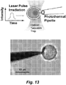
- a cell microsurgery tool is provided where the tool comprises a microcapillary (e.g ., micropipette) having at and/or near the tip a metal film or a plurality of nanoparticles that can be heated by application of electromagnetic energy.
- a cell microsurgery tool comprising a microcapillary having at and/or near the tip a metal film or a plurality of nanoparticles that can be heated by application of electromagnetic energy.
- the microcapillary comprises a hollow bore.
- the tip of the microcapillary ranges in diameter from about 0.01 ⁇ m, 0.05 ⁇ m, 0.1 ⁇ m, or 0.5 ⁇ m to about 1 ⁇ m, 3 ⁇ m, 5 ⁇ m, 8 ⁇ m, or 10 ⁇ m.
- the micropipette has an OD ranging from about 0.5 to about 2 ⁇ m or 3 ⁇ m.
- the nanoparticles range in size from about 50 nm to about 500 nm. In various aspects the nanoparticles range in size from about 10 nm to about 500 nm. In various aspects the nanoparticles are selected from the group consisting of a nanobead, nanowire, a nanotube, a nanodot, a nanocone, and a quantum dot.
- the metal film or nanoparticles comprise a noble metal, a noble metal alloy, a noble metal nitride, and/or a noble metal oxide. In various aspects the metal film or nanoparticles comprise a transition metal, a transition metal alloy, a transition metal nitride, and/or a transition metal oxide.
- the metal film or nanoparticles comprises a magnetic, paramagnetic, or superparamagnetic material.
- the microcapillary comprises a material selected from the group consisting of glass, a mineral, a ceramic, and a plastic.
- the microcapillary comprises a glass microcapillary having nanoparticles near the tip.
- the microcapillary comprises a glass microcapillary having gold nanoparticles near the tip.
- the microcapillary comprises a glass microcapillary where the nanoparticles are predominantly located within 100 ⁇ m of the tip of the microcapillary.
- the methods typically involves contacting the cell with a microsurgery tool as described herein; and applying electromagnetic energy to the tool whereby the temperature of the metal film or metal nanoparticles is increased thereby facilitating penetration of the tool into or through the membrane of the cell.
- the applying electromagnetic energy comprises applying light to heat the metal film or the nanoparticles.
- the applying electromagnetic energy comprises applying a laser beam to heat the metal film or the nanoparticles. While laser heating is generally preferred, other electromagnetic sources are contemplated. Accordingly, in certain aspects the applying electromagnetic energy comprises applying a magnetic field to heat the metal film or the nanoparticles.
- the applying electromagnetic energy comprises applying an electric field to heat the metal film or the nanoparticles.
- the temperature of the metal film or metal nanoparticles is increased at least 100, 150, 200, 250, 300, or 350 degrees Celsius above-ambient.
- the method further comprises injecting a material into the cell through the microcapillary tube.
- the method further comprises removing a material from the cell through the microcapillary tube.
- the microcapillary comprises a hollow bore.
- the tip of the microcapillary ranges in diameter from about 0.1 ⁇ m to about 5 ⁇ m.
- the nanoparticles range in size from about 5 nm to about 500 nm and/or from about 10 nm to about 400nm.
- the nanoparticles are selected from the group consisting of a nanowire, a nanotube, a nanodot, a nanocone, and a quantum dot.
- the metal film or nanoparticles comprise a noble metal, a noble metal alloy, a noble metal nitride, and a noble metal oxide.
- the metal film or nanoparticles comprise a transition metal, a transition metal alloy, a transition metal nitride, and a transition metal oxide.
- the metal film or nanoparticles comprise a magnetic, paramagnetic, or superparamagnetic material.
- the microcapillary comprises a material selected from the group consisting of glass, a mineral (e.g ., quartz), a ceramic, and a plastic (e.g ., polypropynene, polyethylene, polystyrene, DELRIN®, TEFLON®, etc. ) .
- the microcapillary comprises a glass or quartz microcapillary having nanoparticles near the tip.
- the microcapillary comprises a glass microcapillary having gold nanoparticles near the tip.
- the microcapillary comprises a glass microcapillary where the nanoparticles are predominantly located within 100 ⁇ m of the tip of the microcapillary.
- a system for performing microsurgery on a cell comprising a microsurgery tool as described herein, and a micromanipulator (micropositioner) for positioning the microsurgery tool.
- the system further comprises a microscope for visualizing a cell manipulated by the microsurgery tool.
- the system further comprises a pump for delivering or removing a reagent (e.g. , a molecule, organelle, or fluid) using the microsurgery tool.
- the system further comprises an electromagnetic energy source (e.g. , a laser) for exciting the particles/nanoparticles and/or thin film on the microsurgery tool.
- the electromagnetic energy source is selected from the group consisting of a magnetic field generator, a laser, an RF field generator, and the like.
- this disclosure describes methods of preparing a tool for microsurgery on a cell.
- the methods typically involve attaching to a microcapillary tube a plurality of nanoparticles at or near the tip of the microcapillary tube thereby providing a device that can be locally heated by application of electromagnetic energy to the nanoparticles.
- the attaching comprises adsorbing the nanoparticles to the microcapillary.
- the attaching comprises fabricating the nanoparticles in situ on the microcapillary.
- the attaching comprises chemically coupling the nanoparticles to the microcapillary.
- the single-cell surgery tools of this disclosure include atomic force measurement (AFM) tips.
- AFM atomic force measurement
- a nanoparticle can be integrated with an AFM tip for cell surgery applications.
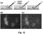
- This nanoparticle integrated AFM tip can cut any desire shape on a cell membrane by scanning the tip and laser pulsing it.
- the tools of this disclosure expressly exclude atomic force measurement (AFM) tips.
- FAM atomic force measurement
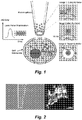
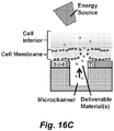
- the devices comprise a surface (e.g. , a transfection substrate) bearing particles and/or nanoparticles and/or a film (e.g. , a thin film) where the particles/nanoparticles and/or thin film comprises a material that heats up when exposed to ( e.g. , irradiated by) an energy source (e.g. , electromagnetic radiation such as a laser).
- an energy source e.g. , electromagnetic radiation such as a laser
- Cells can be disposed on or near the surface, and when the particles/nanoparticles and/or thin film is heated up, openings are formed in the cell (e.g.
- the cell membrane is permeabilized) permitting the introduction or removal of various reagents into or from the cell.
- the surface comprises the surface of a vessel (e.g ., a cell culture vessel, a microtiter plate, a chamber in a microfluidic device, and the like.
- the surface comprises a wall and/or floor of a well in a microtiter plate, a silicon or glass wafer, a microscope slide, a cell culture vessel, or a chamber or channel in a microfluidic device.
- the surface comprises a surface of a chamber configured to contain cells and disposed for viewing with a microscope.
- the surface comprises a surface of a chamber configured to replace a stage on a microscope (e.g. , an inverted microscope).
- the chamber has an open top, while in other embodiments, the top of the chamber is closed.
- the surface comprises a material selected from the group consisting of a glass, a mineral, and a plastic.
- the surface comprises a material selected from Group II materials, Group III materials, Group IV materials, Group V materials, and/or Group VI materials.
- the surface comprises a Group IV material (e.g ., silicon, germanium, etc. ) .
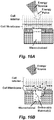
- the surface comprises one or more orifices.
- the nanoparticles and/or thin film is deposited on a surface of the orifice or near the orifice.
- the surface comprises at least two orifices, or at least 3 orifices, or at least 4 orifices, or at least 5 orifices, or at least 8 orifices, or at least 10 orifices, or at least 15 orifices, or at least 20 orifices, or at least 25 orifices, or at least 30 orifices, or at least 40 orifices, or at least 50 orifices, or at least 75 orifices, or at least 100 orifices, or at least 200 orifices, or at least 300 orifices, or at least 500 orifices.
- said orifices are all located within an area of said surface of about 2 cm 2 or less, or about 1 cm 2 or less, or within about 0.5 cm 2 or less, or within about 0.1 cm 2 or less.
- the nanoparticles and/or thin film are disposed within about 100 ⁇ m, or within about 50 ⁇ m, or within about 25 ⁇ m, or within about 20 ⁇ m, or within about 15 ⁇ m, or within about 10 ⁇ m, or within about 5 ⁇ m of said orifice(s).
- the particles/nanoparticles and/or thin film is deposited on a surface of a plurality of the orifices and/or near a plurality of the orifices.
- the particles/nanoparticles and/or thin film is deposited on a surface of a majority of the orifices and/or near a majority of the orifices. In certain embodiments the particles/nanoparticles and/or thin film is deposited on a surface of substantially all of the orifices and/or near substantially all of the orifices. In certain embodiments the nanoparticles and/or a thin film are deposited on a wall and/or all around the lip of the orifice(s). In certain embodiments the nanoparticles and/or a thin film are preferentially on one region of a wall or lip of the orifice(s).
- the nanoparticles and/or a thin film are deposited on the face of the surface and/or on the lip of an orifice on the same side on which cells are disposed. In certain embodiments the nanoparticles and/or a thin film are deposited on the face of the surface and/or on the lip of an orifice opposite the side on which cells are disposed. In certain embodiments the nanoparticles and/or thin film comprise a thin film. In certain embodiments the nanoparticles and/or thin film comprise nanoparticles and the nanoparticles range in size from about 5 nm to about 500 nm.
- the nanoparticle range in size from about 2 nm, or about 5 nm, or about 10 nm, or about 15 nm, or about 20 nm to about 400 nm, or to about 300 nm, or to about 250 nm, or to about 200 nm, or to about 150 nm, or to about 100 nm, or to about 75 nm, or to about 50 nm.
- the nanoparticles are selected from the group consisting of a nanobead or nanosphere, a nanowire, a nanotube, a nanodot, a nanocone, and a quantum dot.
- the nanoparticles and/or thin film comprise a material selected from the group consisting of a semiconductor, a metal, a metal alloy, a metal nitride, and a metal oxide. In certain embodiments the nanoparticles and/or thin film comprise a material selected from the group consisting of a transition metal, a transition metal alloy, a transition metal nitride, and a transition metal oxide. In certain embodiments the nanoparticles and/or thin film comprise a material selected from the group consisting of gold, titanium (Ti), TiN, TiCn, and TiAlN. In certain embodiments the nanoparticle and/or thin film comprise a Group IV material (e.g ., silicon, germanium, etc.
- a Group IV material e.g ., silicon, germanium, etc.
- the nanoparticle and/or thin film comprise silicon or germanium doped with a material selected from the group consisting of boron, arsenic, phosphorous, or gallium.
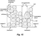
- one or more of the orifices are in fluid communication with a chamber containing a reagent to be delivered into a cell.
- the device comprises a microchannel and one or more of the orifices are in fluid communication with the microchannel.
- the device comprises a plurality of microchannels. In certain embodiments different microchannels are in fluid communication with different orifices.
- the device comprises a manifold and/or valves to deliver fluids to different microchannels.
- the microchannel(s) contain a reagent to be delivered into said cell.
- the reagent is selected from the group consisting of a nucleic acids, a ribozyme, a protein or peptide, an enzyme, an antibody, an organelle, a chromosome, a pathogen, and a microparticle or nanoparticle.
- the microchannel(s) (or the chamber(s)) are pressurized, under control of a pump, fed by a gravity feed, or electrokinetically pumped.
- the device further comprises a controller that monitors and/or controls flow in said microchannel and controls timing and, optionally, location of the illumination of said surface.
- the device is configured to replace the stage on an inverted microscope.
- one or more cells are disposed on the surface and in certain embodiments; the cell(s) are disposed on or adjacent to an orifice in the substrate.
- the cell is a mammalian cell (e.g ., a human cell, a non-human mammalian cell).
- the cell is a stem cell (e.g ., a fetal stem cell, a cord blood stem cell, an adult stem cell, an induced pluripotent stem cell (IPSC), etc. ) .
- a stem cell e.g ., a fetal stem cell, a cord blood stem cell, an adult stem cell, an induced pluripotent stem cell (IPSC), etc.
- systems are described for selectively creating an opening into a cell or a group of cells.
- the system is one for selectively delivering an agent into a cell.
- the system typically comprises a device comprising a transfection substrate ( e.g ., as described above) and a source of electromagnetic energy capable of heating the nanoparticles or thin film.
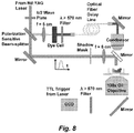
- the source of electromagnetic energy is a laser or a non-coherent light source.
- the source of electromagnetic energy is a laser.
- the system comprises a lens system, a mirror system, or a mask, and/or a positioning system to directing the electromagnetic energy to a specific region of the surface.
- the system comprises a controller that controls the timing and/or pattern of illumination by the source of electromagnetic radiation.
- methods are described for selectively creating an opening into a cell or a group of cells.
- the methods can be used to selectively delivering a reagent (or multiple agents) into a cell.
- the methods utilize the transfection substrates and/or systems ( e.g ., as described above). Accordingly in certain embodiments, a method of delivering a reagent into a cell is provided.
- the method comprises providing cells on a device comprising a transfection substrate ( e.g ., as described above) and/or in a system comprising a device for transfecting cells ( e.g ., as described above) where the cells are disposed on the surface (transfection substrate); contacting the cells with the reagent; and exposing a region of the surface to electromagnetic radiation thereby inducing heating of the thin film and/or particles where the heating forms bubbles that introduce openings in the membrane of cells in (or near) the heated region resulting in the delivery of the reagent into those cells.
- the cells are contacted with the reagent by providing the reagent in a fluid (e.g ., buffer, culture medium) surrounding the cells.
- the cells are contacted with the reagent by providing the reagent in one or more orifices that are present in the surface. In certain embodiments the cells are contacted with the reagent by providing the reagent in one or more microfluidic channels in fluid communication with the orifices. In certain embodiments different reagents are delivered to different orifices. In certain embodiments the exposing comprises exposing a region of the substrate to a laser pulse or to a non-coherent light source. In certain embodiments the reagent is selected from the group consisting of a nucleic acid, a chromosome, a protein, a label, an organelle, and a small organic molecule.
- methods of performing micromanipulations on a cell that utilize the tip of a microcapillary as a light guide and/or to tune the heat distribution at the tip.
- the methods involve contacting the cell with a microsurgery tool, the tool comprising a microcapillary having at and/or near the tip a metal film (coating) or metal nanoparticles that can be heated by application of electromagnetic energy; applying electromagnetic energy to the tool whereby the temperature of the metal film or metal nanoparticles is increased resulting in the formation of an opening in the membrane of the cell, where the contact angle of the microsurgery tool with the cell and/or the polarization of the electromagnetic energy is varied to alter the size and/or shape of the opening introduced into the cell.
- the applying electromagnetic energy comprises applying light (e.g. a laser or non-coherent light) to heat the film or the nanoparticles.
- the tip of the microsurgery tool is configured to act as a light guide.
- the applying electromagnetic energy comprises applying a laser beam to heat the film or the nanoparticles.
- the applying electromagnetic energy comprises applying an electric field and/or a magnetic field to heat metal film or the nanoparticles.
- the temperature of the metal film or metal nanoparticles is increased at least 150°C above-ambient.
- the method further comprises injecting a reagent into the cell through the microcapillary tube.
- the tip of the microcapillary ranges in diameter from about 0.1 ⁇ m to about 5 ⁇ m. In certain aspects the nanoparticles range in size from about 5 nm to about 500 nm.
- the metal film or nanoparticles comprise a semiconductor, or a metal selected from the group consisting of a noble metal, a noble metal alloy, a noble metal nitride, and a noble metal oxide. In certain aspects the metal coating or nanoparticles comprise a transition metal, a transition metal alloy, a transition metal nitride, and a transition metal oxide. In certain aspects the metal coating or nanoparticles comprise a material selected from the group consisting of gold, titanium (Ti), TiN, TiCn, and TiAlN.
- the microcapillary comprises a material selected from the group consisting of glass, a mineral, a ceramic, and a plastic.
- the nanoparticles or film comprises a film. In certain aspects the nanoparticle or film comprises nanoparticles.
- nanoparticles refers to a particle having at least one dimension having an average size equal to or smaller than about 800 nm or 700 nm or 600 nm, or 500 nm, preferably equal to or smaller than about 200 nm or 150 nm, or 100 nm, more preferably equal to or smaller than about 50 or 20 nm, or having a crystallite size of about 10 nm or less, as measured from electron microscope images and/or diffraction peak half widths of standard 2-theta x-ray diffraction scans.
- the first standard deviation of the size distribution is 60% or less, preferably 40% or less, most preferably 15 to 30% of the average particle size.
- range in size indicates that the nanoparticles are predominantly within the size range. Thus, for example, in certain embodiments, at least 85%, preferably at least 90%, more preferably at least 95%., and most preferably at least 98%, 99%, or even all of the nanoparticles are within the stated size range.
- transition metal refers to typically refers to any element in the d-block of the periodic table, excluding zinc, cadmium and mercury. This corresponds to groups 3 to 12 on the periodic table.
- microcapillary tube is a tube that has a tip with a diameter of less than about 50 ⁇ m, preferably less than about 25 ⁇ m, more preferably less than about 15 ⁇ m or 10 ⁇ m, and most preferably less than about 5 ⁇ m.
- the microcapillary has a tip diameter of about 2 ⁇ m or less.
- the microcapillary can be a solid rod.
- the microcapillary can be replaced with a pipette (capillary tube) having a larger tip diameter (e.g., greater than about 200 nm as described herein).
- nucleic acid or “oligonucleotide” or grammatical equivalents herein refer to at least two nucleotides covalently linked together.
- a nucleic acid of the present disclosure is preferably single-stranded or double stranded and will generally contain phosphodiester bonds, although in some cases, as outlined below, nucleic acid analogs are included that may have alternate backbones, comprising, for example, phosphoramide ( Beaucage et al. (1993) Tetrahedron 49(10):1925 ) and references therein; Letsinger (1970) J. Org. Chem. 35:3800 ; Sblul et al. (1977) Eur. J. Biochem.
- polypeptide polypeptide
- peptide protein
- protein polymer of amino acid residues.
- the terms apply to amino acid polymers in which one or more amino acid residue is an artificial chemical analogue of a corresponding naturally occurring amino acid, as well as to naturally occurring amino acid polymers.
- the term also includes variants on the traditional peptide linkage joining the amino acids making up the polypeptide.
- Preferred “peptides”, “polypeptides”, and “proteins” are chains of amino acids whose ⁇ carbons are linked through peptide bonds.
- amino terminus refers to the free ⁇ -amino group on an amino acid at the amino terminal of a peptide or to the ⁇ -amino group (imino group when participating in a peptide bond) of an amino acid at any other location within the peptide.
- carboxy terminus refers to the free carboxyl group on the carboxy terminus of a peptide or the carboxyl group of an amino acid at any other location within the peptide.
- Peptides also include essentially any polyamino acid including, but not limited to peptide mimetics such as amino acids joined by an ether as opposed to an amide bond.
- reagent(s) when used with respect to substances to be delivered into cells include any substance that is to be delivered into (or extracted from) a cell.
- reagents include, but are not limited to nucleic acids (including, for example, vectors and/or expression cassettes, inhibitory RNAs (e.g. , siRHA, shRNA, miRNA, etc. ), ribozymes, proteins/peptides, enzymes, antibodies, imaging reagents, organelles ( e.g ., nuclei, mitochondria, nucleolus, lysosome, ribosome, etc. ), chromosomes, intracellular pathogens, inanimate particles, such as quantum dots, surface-enhanced, Raman scattering (SERS) particles, microbeads, and the like.
- SERS Raman scattering
- this disclosure relates to a new tool/device useful for "surgical" procedures on single cells and to substrates for the manipulation of cells and/or the delivery or extraction of reagents from those cells.
- a "single cell surgical tool” is provided to perform microinjection, microextraction, and/or intracellular manipulations with minimal cell damage. It can be used with any cell bounded by a lipid bilayer (e.g ., a eukaryotic cell, more preferably a vertebrate cell, still more preferably a mammalian cell type). In certain aspects the device can be utilized with cells comprising a cell wall ( e.g. , plant cells).
- the device comprises a microcapillary tube (e.g ., micropipette) comprising "energy absorbent” nanoparticles and/or an "energy absorbent” thin film at or near the tip of the microcapillary.
- a microcapillary tube e.g ., micropipette
- This device achieves precise and controllable nanoscale modification of cells, by excitation/heating (e.g ., laser-induced heating) of the metal particles/nanoparticles and/or a metal film (e.g ., nanocoating) coated on the micocapillary.
- excitation/heating e.g ., laser-induced heating
- a metal film e.g ., nanocoating
- Single-cell microinjection is a powerful and versatile technique for introducing exogenous material into cells, for extracting and transferring cellular components between cells, and/or for the introduction of components not normally found within cells, such as probes, detectors, or genetically engineered organelles, genes, proteins and the like.
- Conventional glass micropipette techniques such as those used to generate transgenic mice, introduce enormous mechanical and biochemical stresses on the cells and yield low rates of success, particularly for mechanically fragile cells.
- the cell surgery tool can achieve manipulations (e.g ., ablation) at a nanometer size scale at or near the tip of a capillary micropipette by local heating of particles/nanoparticles and/or a thin film at or near the pipette tip.
- the particles/nanoparticles and/or thin film are heated using electromagnetic radiation (e.g ., a magnetic field, an electric field, an RF field, broad or focused laser pulses, and the like).
- the cell surgery methods described herein utilize the photothermal effect of metal particles/nanoparticles and/or a thin metal film.
- the material can be "tuned" so that electromagnetic radiation (e.g ., laser energy) is strongly absorbed by particles and/or thin film, but not by nearby cells or cellular contents, thereby avoiding cell or genetic damage caused by traditional laser-based methods of manipulating cells.
- electromagnetic radiation e.g ., laser energy
- Current laser cell techniques rely on strong absorption of the laser power by cellular contents to create ablation or cavitation effects. Such processes can damage cells and can cause undesired breakdown of cellular constituents or chemical effects that may affect the biology of the cells being manipulated.
- the laser or other source of electromagnetic energy
- the energy source e.g ., laser
- the energy source does not substantially damage the cells being manipulated.
- the nanoparticles and/or thin film can be excited (heated) by application of essentially any electromagnetic radiation.
- heating of the nanoparticles and/or thin film(s) is accomplished by application of a magnetic field, and/or an electric field, and/or an RF field, and/or light ( e.g. , a laser).
- metal particles, nanoparticles, and thin films strongly absorb electromagnetic waves with frequencies close to the surface plasmon frequency, usually in the visible and near-IR range. Particles, nanoparticles, and thin films rapidly heat up, due to the absorbed energy, to generate a superheating phenomenon with evaporation of the surrounding medium.
- individual or multiple nanoparticles are coated onto the tip of a micropipette, e.g ., as shown in Figure 1 .
- nanometer diameter vapor bubbles are created around the nanoparticles. When brought nearby or in contact with the surface of a cell, this process generates controlled, precisely-sized holes in the cell membrane (and/or cell wall).
- the micropipette can penetrate the cell membrane with ease without inducing mechanical and biochemical damage associated with current microinjection and extraction techniques.
- the cavitation or "hole punching" process is finished within a few nanoseconds. As a result, the rest of the membrane does not have time to respond and remains mechanically undisturbed.
- the "membrane hole” can be kept open for manipulations with devices, such as fiber optic devices, threaded through the hollow bore of the pipette. In certain aspects similar effects can be obtained using thin metal film deposited at and/or near the tip of the microcapillary.
- the micropipette is positioned next to the targeted cell by micromanipulators and/or automated (e.g ., piezo-driven) stages under a microscope (e.g ., an inverted microscope).
- a microscope e.g ., an inverted microscope.
- the cell surgery tool can thus be used for performing single-cell microinjection, and/or extraction, and/or intracellular manipulation. Hole punching on adherent cell membranes has been demonstrated, and this is easily extended to cells in suspension, to cells immobilized using optical tweezers, and/or to cells that routinely grow in clusters, colonies, or clumps with the assistance of a standard suction-based holding pipette. Illustrative experimental results are shown in Figure 3 .
- different membrane cutting can be accomplished by varying the angle of the pipette (nanoblade) and/or by varying the laser polarization. For example, as the pipette tilts from 0 (vertical) to 30 degrees, the hot spots on the titanium ring move from being at polar opposite to being closer to each other ( see , e.g ., Figure 27 ). The resulting cut in the membrane is "bat eye” shaped ( see , e.g. , Figures 28A-28C ).
- pipette tip size Another factor controlling the cutting pattern (mentioned in Optics Express paper) is the pipette tip size.
- pipette tip size is reduced to 2 micron, heat can diffuse between two hot spots and hence generating one "cat door” shaped cut on the membrane.
- the pipette has titanium coating on both the tip and outer wall of the glass capillary.
- bubble is generated all around the tip (donut).
- Membrane cutting is confined to the area in contact with the pipette tip.
- bubble shape does not vary significantly with pipette tilt or laser polarization, which, in certain aspects, is better suited for microinjection.
- the cell surgery tool can provide precise intracellular access through specifically-sized membrane holes that remain open for periods determined by the operator, or that close rapidly as needed, with minimal to no cell damage for live-cell manipulations.
- the device can be used to increase the efficiency and success rate for performing pronuclear DNA microinjection, embryonic stem cell transfer into blastocysts, somatic cell nucleus transfer, repair or replacement of other intracellular organelles, for the introduction of non-cellular materials, such as probes, and the like.
- methods, devices, and systems are provided for the delivery of agents (e.g ., nucleic acids, proteins, organic molecules, organelles, antibodies or other ligands, etc. ) into live cells and/or the extraction of the same from said cells.
- agents e.g ., nucleic acids, proteins, organic molecules, organelles, antibodies or other ligands, etc.
- the devices comprise a substrate bearing particles (e.g ., nanoparticles) and/or a thin film (e.g. , as described above). Cells can be seeded on this substrate and, optionally grown until a confluent culture forms.
- a pulsed laser (or other electromagnetic energy source) can irradiate the entire substrate, or selectively irradiate a region of the substrate (e.g ., by irradiating a shadow mask whereby the corresponding illumination pattern is imaged onto the substrate).
- the energy source e.g. , pulsed laser
- the particles and/or thin film is heated to high temperatures due to the absorbed energy.
- the heat is dissipated into the liquid medium layer surrounding the particles and/or thin film, thereby generating vapor bubbles.
- irradiation patterns can be selected/designed that induce molecular uptake in specified areas of the cell culture and/or at specified times. Location of the region of uptake on the substrate can be determined by a combination of the pattern of particle/nanoparticles and/or thin films in combination with the pattern of illumination.
- timing of uptake can be controlled by timing of illumination.
- timing of illumination can be controlled by timing of illumination.
- spatially-targeted and/or temporally-targeted molecular delivery is made possible by controlling the particle size, material, and/or density on the substrate and/or film material and/or thickness on the substrate, the energy source timing, intensity and frequency, and the irradiation pattern(s).
- a reagent delivery platform e.g. , a transfection substrate
- a transfection substrate e.g., a transfection substrate
- the nanoparticles and/or thin film can be localized at, on, or near certain features (e.g ., pores protuberances, channels, and the like) that are fabricated on the substrate.
- the particles/nanoparticles and/or thin film is disposed on the "top side" of the substrate (where the cell(s) are disposed), while in other embodiments, additionally or alternatively, the particles/nanoparticles and/or thin film is disposed on the bottom side of the substrate ( e.g ., the side opposite the side upon which the cells are disposed).
- the energy absorbing films or particles e . g ., metal particles/ nanoparticles, and/or thin films
- nanometer diameter vapor bubbles are created around the nanoparticles or thin film and when in contact or nearby the surface of a cell, this process generates controlled, precisely-sized holes in the cell membrane (and/or cell wall) to permit the entry or exit of, for example, a reagent.
- the cavitation or "hole punching" process is finished within a few nanoseconds. As a result, the rest of the membrane does not have time to substantially respond and remains mechanically relatively undisturbed.
- such devices can comprise one or more microfluidic orifices ( e.g. , on/into/through a substrate) with the energy absorbing film (e.g. , a Ti film) or nanoparticles disposed on the lip of, and/or on the side-wall of, the orifice(s) (or near to the edge of the orifices) ( see, e.g. , Figure 14 and Figure 18 ).
- the device comprises arrays of microfluidic orifices (e.g.
- the orifice(s) can be connected to one or to a network of channels ( e.g. , microfluidic channels). Cells can be disposed on or near the orifice(s).
- the substrate comprises rows of orifices where each row is joined by a microchannel.
- two manifolds are provided that each deliver reagents into two microchannels.
- the surfaces near or comprising the orifices are coated with a thin film (e.g. , a thin film comprising Ti) and/or nanoparticles that are selectively heated when illuminated.
- Selective areas e.g. , illumination areas 1 and 2 of the substrate can be illuminated as desired to effect delivery of the reagents into cells disposed within the illumination area.
- Figure 15 illustrates two manifolds, in various embodiments, more or fewer manifolds are contemplated. Additionally or alternatively, delivery of reagents to orifices can be controlled by a valve system. In certain embodiments the manifolds can be eliminated.
- a reagent delivery platform is provided by integrating energy absorbing films and/or micro- or nanoparticles on microfluidic structures.
- Such devices can comprise one or more microfluidic orifices ( e.g ., on/into/through a substrate) with the energy absorbing film (e.g. , a Ti film) or nanoparticles disposed on the lip of, and/or on the side-wall of, the orifice(s) (or near to the edge of the orifices) ( see , e.g. , Figure 14 ).
- the device comprises arrays of micro fluidic orifices (e.g.
- the orifice(s) can be connected to one or to a network of channels ( e.g ., microfluidic channels). Cells can be disposed on or near the orifice(s).
- openings form in the cell membrane and/or cell wall, and reagents in the microfluidic channel(s) can be delivered into the cells by diffusion, or by pumping the fluid through the microchannel(s) using for example, an external pressure source.
- the orifice(s) range in diameter from about 1 ⁇ m up to about 100 ⁇ m or up to about 50 ⁇ m, or from about 2 ⁇ m or about 5 ⁇ m up to about 20 ⁇ m or 30 ⁇ m, or from about 1 ⁇ m, or 2 ⁇ m, or about 5 ⁇ m, up to about 10 ⁇ m, or about 15 ⁇ m, or about 20 ⁇ m, or about 25 ⁇ m, or about 30 ⁇ m, or from about 5 ⁇ m up to about 10 ⁇ m, 15 ⁇ m or 20 ⁇ m. In certain embodiments the orifice(s) are about 10 ⁇ m in diameter.
- the microfluidic channels have a width and/or a depth of about 1000 ⁇ m or less, or a width and/or a depth (or diameter or characteristic dimension) of about 800 ⁇ m or less, or a width and/or a depth (or diameter or characteristic dimension) of about 500 ⁇ m or less, or a width and/or a depth (or diameter or characteristic dimension) of about 400 ⁇ m or less, or a width and/or a depth (or diameter or characteristic dimension) of about 300 ⁇ m or less, or a width and/or a depth (or diameter or characteristic dimension) of about 200 ⁇ m or less, or a width and/or a depth (or diameter or characteristic dimension) of about 150 ⁇ m or less, or a width and/or a depth (or diameter or characteristic dimension) of about 100 ⁇ m or less, , or a width and/or a depth (or diameter or characteristic dimension) of about 50 ⁇ m or less, , or a
- reagents e.g ., as described herein
- reagents can be selectively delivered to cells on top or in proximity to the irradiated/heated orifice.
- materials to be delivered in appropriate microchannel(s) the same material or different materials can be delivered to different cells on the same substrate.
- the "addressable" delivery devices/substrates described herein can be used in a wide variety of contexts. For example, in high throughput systems (different wells or different regions of a single well can have reagents selectively delivered into the target cells simply by administering the agent to the medium and irradiating (e.g ., with laser radiation) the region containing the cells into which the agent is to be transported. The first agent can then be washed out, a second agent applied, and a different region irradiated thereby producing cells transfected with different agents at different locations in the culture. This facilitates massively parallel processing of cells permitting the extraordinary control over the timing and spatially addressable delivery of one or more agents.
- irradiating e.g ., with laser radiation
- the materials to be transfected into the cells are provided in microchannels in fluid communication with orifices on the substrate, the devices need not be operated in this modality.
- the materials to be transfected into the cells can be provided in the culture medium. Selective heating of a region at or near a cell forms a pore into the cell thereby transfecting the material into the cell.
- the nanoparticle or thin film regions can be on an portion of the surface an need not be associated with apertures/orifices.
- the devices described herein can be integrated for example, with other microfluidic devices with pumps and valves (e.g ., lab on a chip) for delivery of particular agents to cells.
- pumps and valves e.g ., lab on a chip
- the configuration of such "transfection substrates" and microfluidic devices can be routinely varied changing for example, the features on the substrate (e.g ., pore (orifice) size, size distribution, spatial distribution) can be changed, the type of film and/or nanoparticles, the distribution and/or confgiguration of microfluidic channels, and the like.
- the nanoparticles and/or thin film(s) comprising the surgical devices and/or substrates described here can be excited (heated) by application of essentially any of a variety of methods.
- Such methods include, but are not limited to application of microwaves, lasers, non-coherent optical radiation (e.g ., infrared radiation), electrical heating, electron spin resonance (ESR) heating, magnetic heating, and the like.
- heating of the nanoparticles and/or thin film(s) is accomplished by application of a magnetic field, and/or an electric field, and/or an RF field, and/or light ( e.g. , a laser).
- metal particles/nanoparticles, and/or thin films strongly absorb electromagnetic waves with frequencies close to the surface plasmon frequency, usually in the visible and near-IR range. Particles, nanoparticles, and thin films rapidly heat up, due to the absorbed energy, to generate a superheating phenomenon with evaporation of the surrounding medium.
- the surgical device and/or substrate is to be selectively heated (e.g. , a portion of the substrate)
- any means of locally/selectively illuminating the device or substrate can be used.
- local illumination of a particular region of the substrate can be accomplished by using, e.g. , a focused laser, a focused non-coherent light (e.g. , infrared) source.
- selective illumination of one or more regions of a substrate is accomplished by using a mask (shadow mask).
- local illumination can be achieved simply by focusing the illuminating energy source (e . g ., laser) to a particular region using a lens and/or mirror system.
- the energy source can be focused at a fixed region and the substrate moved ( e.g ., using a movable stage or other manipulator) to achieve local illumination of particular regions.
- the illumination area can take any desired shape.
- the illuminated area is circular, square, elliptical, hexagonal, crescent shaped, or any other regular or irregular shape.
- multiple areas of the substrate are illuminated either simultaneously, or sequentially.
- the energy pulses (e.g ., laser pulses) can be shaped by not only the static shadow masks as demonstrated in the examples, but also by dynamic masks using a spatial light modulator such as a TI's DMD microdisplay or LCD display. This provides real-time and interactive control of microinjection into target cells.
- single cell surgery devices comprising a micropipette having at or near the tip particles or nanoparticles and/or thin films that can be heated using a source of electromagnetic energy (e.g. , a laser).
- cell transfection devices comprising a substrate (e.g . a cell culture vessel, a microtiter plate, etc. ) comprising nanoparticles and/or thin films that can be heated using a source of electromagnetic energy (e.g. , a laser).
- micropipettes and "transfection substrates" described herein can be fabricated using methods known to those of skill in the art.
- an injection micropipette is fabricated using, for example, a commercial pipette puller, while substrates can be fabricated using micro fabrication methods known in the semiconductor industry.
- the microcapillary/micropipette can be fabricated from any material that can be pulled, etched, or otherwise fabricated to the desired dimension(s) while providing the requisite stiffness and heat resistance to permit heating and cell penetration.
- the material is preferably not toxic to the cell(s) of interest.
- the microcapillary comprises a material such as glass, a mineral (e.g ., quartz), a ceramic, a plastic ( e.g. , DELRIN®, TEFLON®, etc. ), a metal, a semiconductor, and the like.
- the cross-sectional shape of the pipette is typically circular. However, this does not mean that only circular pipettes can be used for the cell surgery tool. Micropipettes having other cross-sections can be fabricated. For example, pipette tips with any desired patterns, circular, rectangular, or triangular can be fabricated on a glass or silicon wafer first and then transferred and assembled with an injection pipette.
- Pipette diameter is an important parameter for the single-cell surgery instrument.
- One advantage of the single-cell surgery instrument described herein is that it allows opening a ⁇ m size hole in a cell membrane with less collateral damage to the cell. This allows the delivery large size DNAs or other materials into a cell without killing it.
- conventional micropipette techniques typically require the outer tip diameter of a glass pipette to be smaller than 200 nm to facilitate the penetration across the flexible cell membrane of small mammalian cells. This restriction greatly limits the size of particles that can be delivered through conventional micropipette techniques. Materials such as chromosomes, nuclei, organelles, or other extracellular materials have great research and commercial value, but often have a size larger than the physical size of the pipette opening and cannot be introduced into cells through conventional techniques.
- the "laser" cell surgery pipette described herein provides a unique solution to this problem which has the potential to revolutionize the entire micropipette industry.
- the methods and devices of this invention are effective to introduce large DNA fragments (e.g ., BAC-sized or larger DNA), nuclei, organelles, and other large moieties into cells more efficiently with less cell damage than other techniques.
- the micropipette comprising the single cell surgery tool described herein has a tip diameter greater than 200 nm, in certain aspects greater than about 300 nm, greater than about 400 nm, greater than about 500 nm, greater than about 600 nm, greater than about 700 nm, greater than about 800 nm, or greater than about 900 nm or 1 ⁇ m.
- the substrate(s) comprising the "transfection substrate” can be fabricated from any convenient material that is preferably not toxic to the cell(s), that can carry the particle, nanoparticle, or thin film coating, and that can tolerate the local heating produced by application of electromagnetic energy to the particles, nanoparticles, and/or thin film(s).
- Suitable materials include, but are not limited to glass/silicion, germanium, a mineral (e.g. , quartz), a ceramic, a plastic ( e.g. , DELRIN®, TEFLON®, etc. ) , a metal, a semiconductor, and the like.
- the substrate comprises a surface of a vessel used for cell screening and/or for cell culture.
- a vessel used for cell screening and/or for cell culture can include, for example, vessels for adherent or suspended cell culture.
- This can also include, microtiter plates ( e.g. , 96, 384, 864, 1536 well, etc. ), microfluidic devices, high density (microarray) substrates, microscope slides or chambers, and the like.
- the cell transfection substrates are fabricated using techniques known in the semiconductor industry.
- One approach is schematically illustrated in Figure 17 .
- the microfluidic orifices and channels are fabricated by patterning SU-8 photoresists on a glass coverslip substrate.
- First the bottom trenches are defined photolithographically in a layer of 100- ⁇ m-tall SU-8 2075 photoresist.
- Another thin layer (4 ⁇ m thick) of SU-8 2005 photoresist is spun coated onto the bottom layer and circular openings are defined by a second photolithography step.
- 100 nm thick Ti thin film is deposited onto the structure by electron beam evaporation at a substrate incline angle of 60 degrees to coat both the top and the sidewalls of the circular orifices.
- Final steps involve dry etching the top layer Ti and connecting the microchannels to an external fluidic pump.
- Bottom trenches in one illustrative embodiment were 200 ⁇ m wide and 300 ⁇ m apart.
- the circular orifices had diameters ranging from 10 to 20 ⁇ m. These orifices were arranged in a square array and separated by 100 ⁇ m. A new-moon shaped Ti thin film was coated on the sidewalls of the circular orifices.
- orifices are circular, they need not be so limited. Using standard methods (e.g. , etching methods) orifices of essentially any shape ( e.g. , round, square, pentagonal, hexagonal, ellipsoid, trapezoidal, irregular, etc. ) can be produced. Similarly, the patterning of the orifices can be in essentially any desired pattern.
- the nanoparticles and/or thin film are coated on a portion of the orifice ( e.g. , by depositing the film at an angle) in certain other embodiments, the orifice and/or remaining surface is uniformly coated with nanoparticles and/or a thin film.
- the particles and/or nanoparticles or thin film(s) comprising the various devices described herein are all formed of the same material.
- particles and/or nanoparticles or thin film(s) in a particular device include different materials.
- a given device e.g ., pipette or transfection substrate
- the thin films comprising the devices can comprise multiple films ( e.g. , as multiple layers, or different films at different locations on the micropipette or substrate).
- the devices can be modified by coating another layer of metal, or dielectric materials (e.g ., silicon oxide, silicon nitride, etc. ) on top of the metal thin film to control the heat dissipation pathways and to control the microbubble expansion patterns which effects the amount of area on the cell that is damaged by the substrate heating or by the pipette tip.
- metal or dielectric materials (e.g ., silicon oxide, silicon nitride, etc. ) on top of the metal thin film to control the heat dissipation pathways and to control the microbubble expansion patterns which effects the amount of area on the cell that is damaged by the substrate heating or by the pipette tip.
- the particles/nanoparticles and/or thin films on the micropipette and/or "transfection substrate” are fabricated from a metal, metal alloy, semiconductor, or other material that can be heated by the application of appropriate electromagnetic energy.
- semiconductors, metals, metal alloys, and oxides and/or nitrides thereof are contemplated.
- such metals are readily heated using various energy sources (e.g ., laser light, electric field, RF field, magnetic field, ultrasonic source, etc. ) .
- nanoparticles and/or films comprising materials such as gold, silver, tantalum, platinum, palladium, rhodium, or titanium, or oxides, nitrides, or alloys thereof are contemplated.
- the nanoparticles and/or thin film(s) comprising devices and methods described herein comprise titanium and/or titanium nitride (TiN), which is a very hard material with a melting temperature three times higher than gold.
- TiN titanium nitride
- 40 cells have been consecutively injected using one single pipette without seeing any pipette damage. This also means that a TiN coated pipette can potentially inject hundreds or thousands of cells without the need to change the pipette. This is a significant improvement as compared to a gold coated pipette, which can be damaged by the strong explosive bubbles and high temperature excitation in one, two, or a few uses.
- TiN titanium carbon nitride
- TiAlN titanium aluminum nitride
- the particle or films comprising the devices and/or substrates described herein need not be limited to materials comprising metals.
- black carbon can also induce explosive bubbles near the pipette and kill or penetrate a single cell.
- carbon nanoparticles including, but not limited to carbon nanotubes can be used in the methods and devices described herein.
- particles/nanoparticles, and/or thin films comprising one or more materials from Groups II, III, IV, V, or VI of the periodic table are also contemplated as well as oxides, nitrides, alloys, and doped forms thereof and/or transition metals, transition metal oxides, transition metal nitrides, alloys or composites comprising transition metals, and the like are contemplated.
- the nanoparticles and/or films comprise Group II, Group III, Group IV, Group V materials (e.g., carbon, silicon, germanium, tin, lead), doped Group II, III, IV, V, and VI elements, or oxides of pure or doped Group II, III, IV, V, or VI elements or transition metals, transition metal oxides or transition metal nitrides.
- the particles/nanoparticles and/or thin films comprise a Group III, IV, or V semiconductor.
- the particles/nanoparticles and/or thin films include one or more materials such as Si, Ge, SiC, Au, Ag, Cu, Al, Ta, Ti, Ru, Ir, Pt, Pd, Os, Mn, Hf, Zr, V, Nb, La, Y, Gd, Sr, Ba, Cs, Cr, Co, Ni, Zn, Ga, In, Cd, Rh, Re, W, and their oxides and nitrides.
- materials such as Si, Ge, SiC, Au, Ag, Cu, Al, Ta, Ti, Ru, Ir, Pt, Pd, Os, Mn, Hf, Zr, V, Nb, La, Y, Gd, Sr, Ba, Cs, Cr, Co, Ni, Zn, Ga, In, Cd, Rh, Re, W, and their oxides and nitrides.
- the group II, III, IV, V, or VI element, transition metal, transition metal oxide or nitride comprising the nanoparticle(s) and/or thin film can be essentially pure, or it can be doped (e.g ., p- or n-doped) and/or alloyed.
- P- and n-dopants for use with Group II-VI elements, in particular for use with Groups III, IV, and V elements, more particularly for use with Group IV elements (e.g ., silicon, germanium, etc. ) are well known to those of skill in the art.
- Such dopants include, but are not limited to phosphorous compounds, boron compounds, arsenic compounds, aluminum compounds, and the like.
- the particles/nanoparticles and/or films comprise Group IV semiconductors such as silicon, germanium, and silicon carbide.
- Group IV semiconductors such as silicon, germanium, and silicon carbide.
- the most common dopants for such semiconductors include acceptors from Group III, or donors from Group V elements.
- Such dopants include, but are not necessarily limited to boron, arsenic, phosphorus, and occasionally gallium.
- the particles/nanoparticles comprise a semiconductor.
- Many doped Group II, III, IV, V, or VI elements are semiconductors and include, but are not limited to, ZnS, ZnSe, ZnTe, CdS, CdSe, CdTe, MgS, MgSe, MgTe, CaS, CaSe, CaTe, SrS, SrSe, SrTe, BaS, BaSe, BaTe, GaN, GaP, GaAs, GaSb, InP, InAs, InSb, AlS, AlP, AlSb, PbS, PbSe, Cd 3 Sb 2 , Zn 3 P 2 , Zn 3 As 2 , Zn 3 Sb 2 , TiO 2 , TiO 2 , TiO 2 , Cu 2 O, CuO, UO 2 , UO 3 , Bi 2 O 3 , SnO 2 , BaTiO 3 , Sr
- U.S. Patent Publication No: 2007/0164250 provides magnetic nanoparticles, that when placed in a magnetic field are selectively heated at a certain frequency of the magnetic field, as a function of their size, composition, or both.
- such nanoparticles or films comprise magnetic materials (such as the Ferro V magnetic pigment) that transduce energy when exposed to a magnetic field of sufficient intensity.
- an alternating magnetic field will induce an alternating current in the particle, producing heat.
- magnetic materials include, but are not limited to magnetic materials, such as Fe-O 4 , Fe 2 O 3 .
- silver, copper, platinum, palladium and the like can comprise the particles, nanoparticles, and/or thin films used in the devices of this invention.
- the particles, nanoparticles, and/or thin films can comprise TiO 2 , CeO 2 , Ag, CuO, yttrium aluminum garnet (YAG), InO 2 , CdS, ZrO 2 , or a combination thereof.
- any metal oxide, metal alloy, metal carbide, and/or transition metal may be used in the instant invention.
- the particles can be coated, such that the coating does not alter their respective responsiveness to the applied field.
- particles, nanoparticles, or thin films used in the devices of the present invention can be made of magnetic materials, while in other embodiments, they can be made of or comprise paramagnetic or superparamagnetic materials.
- the particles, nanoparticles and/or thin films can comprise a paramagnetic or superparamagnetic material that can be heated using electron spin resonance absorption (SPM) and/or ferromagnetic resonance.
- SPM electron spin resonance absorption
- FMR ferromagnetic resonance
- ESR Electron spin resonance
- FMR ferromagnetic resonance
- Yttrium-iron garnet Y 3 Fe 5 O 12 and ⁇ -Fe 2 O 3 are two well-known materials suitable ESR and/or FMR heating. Different dopants can be added to lower the spin resonance frequencies of these materials various applications.
- Magnetic garnets and spinels are also chemically inert and indestructible under normal environmental conditions.
- Garnet ⁇ c ⁇ 3 (a) 2 [d] 3 O 12 Spinel A[B] 2 O 4 ⁇ c ⁇ (a) octahedral A [B] dodecahedral [d] tetrahedral tetrahedral octahedral Y 3+ Fe 3+ Fe 3+ Fe 3+ La 3+ Mn 2+ Mn 2+ Mn 2+ Gd 3+ Ru 3+ Ru 3+ Ru 3+ Eu 2+ Cu 1+ Cu 1+ Cu 1+ Na 1+ V 3+ [d], Ni 2+ (a) V 3+ Ni 2+ K 1+ Cr 4+ [d], Cu 3+ (a) Cr 4+ Cu 3+ Rb 1+ Mo 4+ [d], Cr 3+ (a) Mo 4+ Cr 3+ Tl 1+ W 4+ [d], Mo 3+ (a) W 4+ Mo 3+ Ag 1+ Nb 3+ [d], W 3+ (a) Nb 3+ W 3+ Au 1+ Zn 2+ Zn 2+ Zn 2+
- the particle or nanoparticles can take any of a number of possible morphologies and still be suitable for use in the present invention.
- this invention contemplates using nanotubes of the following kinds: single walled, double walled, multi walled, with zig-zag chirality, or a mixture of chiralities, twisted, straight, bent, kinked, curled, flattened, and round; ropes of nanotubes, twisted nanotubes, braided nanotubes; small bundles of nanotubes ( e.g ., in certain embodiments, with a number of tubes less than about ten), medium bundles of nanotubes ( e.g ., in certain embodiments, with a number of tubes in the hundreds), large bundles of nanotubes ( e.g .
- nanostructures can assume heterogeneous forms.
- Such heterogeneous forms include, but are not limited to structures, where one part of the structure has a certain chemical composition, while another part of the structure has a different chemical composition.
- An example is a multi walled nanotube, where the chemical composition of the different walls can be different from each other.
- Heterogeneous forms also include different forms of nanostructured material, where more than one of the above listed forms are joined into a larger irregular structure.
- any of the above materials can have cracks, dislocations, branches or other impurities and/or imperfections.
- the size of the particles or nanoparticles and/or the area and/or thickness of the thin film(s) for use in the present invention can be adjusted or optimized and reflect the choice of the nanoparticles or film material, the nature of the excitation energy, and frequency and/or strength of the excitation energy.
- the nanoparticles range in size (e.g ., length and/or width and/or diameter) from about 10 to about 500 nm, preferably from about 20 nm to about 200nm, more preferably from about 20 nm, 30 nm, 40 nm or 50 nm to 100 nm, or 150 nm or 200 nm.
- the size of the nanoparticles for use in the present invention ranges from about 4 nm to about 25 nm, in another embodiment, from 8 nm to 5 nm, in another embodiment from 5 nm to 100 nm, in another embodiment, from 10 nm to 800 nm, in another embodiment, from 10 nm to 50 nm, in another embodiment, from 50nm to 200 nm, and in another embodiment from 150 nm to 500 nm.
- metal films range in thickness from about 1, 2, 5, 10, 50, 100, 150, 200, 300, 400, or 500 nm to about 800 nm, 1 ⁇ m, 5 ⁇ m, 10 ⁇ m, 50 ⁇ m, or 100 ⁇ m. In certain embodiments the metal films range in thickness from about 2 nm or 5 nm, 10 nm, 20 nm, or 30 nm to about 100 nm, 300 nm, 500 nm, 800 nm or 1 ⁇ m.
- the metal films range in thickness from 1 nm to 150 nm, preferably from about 5 nm to 100 nm, more preferably from about 5 nm, 10 nm, or 20 nm to about 50 nm, 75 nm, or 100 nm. In certain embodiments the metal films are about 30 nm in thickness.
- the coated layer comprising the devices described herein can be a continuous thin film, a thin film broken up into small domains (e.g ., 5 nm, 10 nm, 20 nm, 50 nm, 100 nm, 200 nm, 500 nm domains), or can comprise discrete particles or nanoparticles as described herein.
- the shape of the particles and the thickness of thin films as well as the particle or film composition will affect the absorption spectrum of the material and the energy source and intensity required to produce the desired local heating.
- the film thickness and/or particle size effects the size of the bubble(s) produced by local heating and the nature of the microfluidic flow near the bubbles. This determines the shear stress produced and the size of the opening(s) produced in the cell.
- the larger the particles the larger the bubbles produced and the more impact produced on the cell.
- the thickness of thin films has a similar effect as the particle size. The thicker the film, the larger the bubble produced and the larger the hole(s) produced in the cell(s).
- thin films can be deposited by any suitable method including but not limited to sputtering deposition, chemical vapor deposition (CVD), molecular beam epitaxy (MBE), plasma-assisted vapor deposition, cathodic arc deposition or Arc-PVD, and electron beam evaporation deposition.
- CVD chemical vapor deposition
- MBE molecular beam epitaxy
- plasma-assisted vapor deposition cathodic arc deposition or Arc-PVD
- electron beam evaporation deposition electron beam evaporation deposition
- the film will partially or fully cover the tip of the microcapillary to a distance of up to 100 ⁇ m, 50 ⁇ m, 25 ⁇ m, 10 ⁇ m, or 5 ⁇ m from the tip, to a distance of up to 1 ⁇ m from the tip, more preferably to a distance of up to 800 nm, preferably up to 500 nm, more preferably up to 300, 200, 150, 100, 50, or 25 nm from the tip.
- Thin films can also be chemically deposited on the microcapillary or cell transfection substrate.
- Such methods include, but are not limited to combustion synthesis (e.g ., using an oxidizer (e.g ., metal salt) and a fuel (e.g ., organic compounds) in a redox reaction), evaporation/condensation (EC) generators, spray pyrolysis (e.g ., plasma processing and powder spray), liquid phase methods using solution chemistry such as supercritical fluids, chemical reduction, or chemical oxidation, mechanical alloying, template methods (e.g., forming nanoparticles within small voids or areas.
- combustion synthesis e.g ., using an oxidizer (e.g ., metal salt) and a fuel (e.g ., organic compounds) in a redox reaction)
- EC evaporation/condensation
- spray pyrolysis e.g ., plasma processing and powder spray
- liquid phase methods using solution chemistry such as supercritical fluids, chemical reduction, or chemical oxidation, mechanical alloying
- template methods e.
- the nanoparticles are synthesized in surfactant systems.
- surfactant-based methods are well known to those of skill in the art. One such approach is illustrated in Example 1.
- nanoparticles can be formed on the reduction of metallic salts by organic solvents (e.g ., ethanol) to form metal colloids (see, e.g., Hirai et al. (1979) J. Macromol. Sci. Chem., A13: 727 ; Hirai et al. (1976) Chem. Lett., 905 ; Toshima and Yonezawa (1992) Makromol. Chem., Macromol. Symp., 59: 281 ; Wang and Toshima (1997) J. Phys. Chem., 97: 11542 , and the like).
- organic solvents e.g ethanol
- magnetite nanoparticle materials can be made by mixing iron salt with alcohol, carboxylic acid and amine in an organic solvent and heating the mixture to 200-360°C.
- the size of the particles can be controlled either by changing the iron salt to acid/amine ratio or by coating small nanoparticles with more iron oxide.
- Magnetite nanoparticles in the size ranging from 2 nm to 20 nm with a narrow size distribution can readily be obtained.
- the method can easily be extended to other iron oxide based nanoparticle materials, including MFe 2 O 4 (where M is for example Co, Ni, Cu, Zn, Cr, Ti, Ba, Mg, and the like) nanomaterials, and iron oxide coated nanoparticle materials.
- the method also leads to the synthesis of iron sulfide based nanoparticle materials by replacing alcohol with thiol in the reaction mixture.
- the magnetite nanoparticles can be oxidized to ⁇ -Fe 2 O 3 , or ⁇ -Fe 2 O 3 , or can be reduced to bcc-Fe nanoparticles, while iron oxide based materials can be used to make binary iron based metallic nanoparticles, such as CoFe, NiFe, and FeCoSmx nanoparticles (see, e.g ., U.S. Patent 7,128,891 ).
- One method of producing gold nanoparticles involves mixing a gold salt solution with an adsorbent.
- Gold in the form of complexes is adsorbed onto the surface of the adsorbent.
- the gold-loaded adsorbent after being separated from the solution by screening, filtration, settling or other methods, is ashed to form ashes.
- the ashes contain gold nanoparticles and impurities such as oxides of sodium, potassium and calcium.
- the impurities can be removed by dissolution using dilute acids.
- the relatively pure gold nanoparticles are obtained after the impurities are removed.
- Activated carbon or gold-adsorbing resin can be used as the adsorbent.
- Silver or platinum group metal nanoparticles can also readily be produced by this method ( see, e.g ., U.S. Patent No: 7,060,121 .
- nanoparticles can be formed using laser pyrolysis.
- Conventional laser pyrolysis processes often called photothermal processes, are well known to those of skill in the art (see , e.g ., U.S. Patents 5,958,348 , 3,941,567 . 6,254,928 , and the like).
- a radiation absorber or other precursor gaseous species absorbs energy (e.g ., laser light, which results in the heating of the materials in a reaction zone causing thermally driven chemical reactions between the chemical components in the reaction zone.
- laser pyrolysis processes employ a precisely defined hot zone (typically 1000 ⁇ 1500°C) generated, e.g ., by a laser beam passing through a chemical vapor zone, in which gases thermally react to form the desired nanoscale particulate materials.
- a precisely defined hot zone typically 1000 ⁇ 1500°C generated, e.g ., by a laser beam passing through a chemical vapor zone, in which gases thermally react to form the desired nanoscale particulate materials.
- the absence of wall in contact with the hot zone eliminates any contamination.
- the materials formed in the pyrolytic reaction leave the hot zone typically driven by gravity or gas flow.
- the materials are rapidly cooled/quenched thereby forming nanoparticles with a very uniform distribution of sizes and shapes.
- a carbon dioxide (CO 2 ) laser is used to heat the gas molecules directly by light absorption.
- Another advantage of using a laser is its narrow spectral width, which allows efficient coupling between the light and the molecular precursor that has exact wavelength of absorption (over 15% of laser power consumed).
- the technology has been used to produce various nanosize materials from metals, metal carbides, metal nitrides and metal oxides ( see , e.g ., Haggerty et al.
- TiN thin film creation the most common methods of TiN thin film creation are physical vapor deposition (PVD, usually sputter deposition, Cathodic Arc Deposition or electron beam heating) and chemical vapor deposition (CVD). In both methods, pure titanium is sublimated and reacted with nitrogen in a high-energy, vacuum environment.
- PVD physical vapor deposition
- CVD chemical vapor deposition
- Bulk ceramic objects can be fabricated by packing powdered metallic titanium into the desired shape, compressing it to the proper density, then igniting it in an atmosphere of pure nitrogen. The heat released by the chemical reaction between the metal and gas is sufficient to sinter the nitride reaction product into a hard, finished item.
- the particles or nanoparticles can be attached to the microcapillaries or cell transfection substrate by any of a number of methods known to those of skill in the art.
- the particles can simply be sputtered in place, formed on the surface during the formation of metal colloids, grown in place on nucleating particles, ionically attached to the surface, or covalently coupled to the surface, e.g ., directly or through a linker/functionalizing agent (e.g ., -SH, silane ( e.g ., 3-aminopropyltirmethoxysilane, and the like), and so forth.
- a linker/functionalizing agent e.g ., -SH, silane (e.g ., 3-aminopropyltirmethoxysilane, and the like
- the cell transfection substrate is fabricated by bombarding gold particles directly onto a plastic substrate using a biolistic cell injector (BioRad) (see, e.g. , Example 4, and Figure 5 ).
- BioRad biolistic cell injector
- fabrication can involve depositing a layer of adhesion metal (e.g . titanium, chromium) followed by a layer of gold (or other metal) film on glass, or plastic, or quartz, etc. substrates.
- adhesion metal e.g . titanium, chromium
- gold or other metal
- the sample is then heated (e.g ., irradiated with laser pulses).
- the metal films melt, and the molten metal condenses to form beads-like particles (as seen in SEM images in Figure 6 ) on the substrate or micropipette.
- the optional adhesion metal (e.g ., titanium) layer sandwiched between the substrate and the gold layer provides a stronger adhesion of the gold film as well as the gold beads after annealing to the substrate.
- gold can still be annealed into nanoparticle beads on the surfaces by laser pulses or other heating methods.
- a substrate or micropipette bearing a thin film.
- the thin film is then etch away to leave nanoscale size domains that can be heated by applying a laser or other energy source.
- the particle array fabrication method(s) can be extended to other micro or nanofabrication techniques such as nanoimprint, e-beam lithography, and others.
- the current plastic substrate can be replaced with other polymer materials such PDMS or a glass substrate, or a silicon substrate, or others.
- Optical tweezers have been shown to trap and manipulate micron- and even submicron-sized objects and biological contents.
- the trapping force of optical tweezers is typically on the order of piconewtons. As a result, it is generally not possible to use optical tweezers to anchor the non-adherent cells during conventional glass microcapillary injections.
- the plasmonic photothermal pipette (single surgery tool of this disclosure), on the other hand, can readily be combined with optical tweezers.
- the manipulated cells are self-aligned to the injection position by the optical forces.
- cells experience minimal sheer force and mechanical distortion which are two critical parameters to keep the injected cells alive.
- the optical tweezers integrated laser cell surgery technique has the potential to achieve high speed and high efficiency microinjection for non-adherent cells.
- the methods and devices described herein can be used with essentially any cell having a cell membrane.
- the methods and devices can also be used on cells having a cell wall.
- adherent cells including NIH3T3 mouse fibroblasts, HEK293T embryonic kidney fibroblasts, and HeLa cervical carcinoma cells have been injected GFP-expressing plasmids using the devices and methods described herein.
- any adherent mammalian cell type can be easily injected using the devices and methods described herein because: 1) the laser fluence that is determined as optimal in terms of effective hole-punching and maintaining cell viability is lies with in a relatively narrow range for all the cell types tested; and 2) adherent cell features used to determine appropriate injection location (e.g ., perinuclear or possibly nuclear) are easily identified visually.
- Lymphocytes stem cells of various types, germ cells and others are non-adherent, but it is often desirable to inject or perform other "surgical" procedures on such cells. Integration of optical tweezers with the cell surgery tool as described herein, makes this possible.
- injecting individual cells within a cell cluster is achievable especially on the surface of stem cell clusters using the methods and devices described herein. It is also believed to be possible to stereotactically inject specific cells within clusters, which is desirable for a variety of reasons ( e.g ., developmental tracking, establishing gradients, etc. ) .
- any desired material into a cell using the methods and devices described herein.
- Such materials include, but are not limited to nucleic acids, proteins, organelles, drug delivery nanoparticles, probes, labels, and the like. Delivery of plasmid DNAs into cells using the methods described herein as been demonstrated already in at least three adherent cell types. Accordingly any plasmid-sized genetic material should be easily transferred by the methods and devices described herein.
- BACs bacterial artificial chromosomes
- BACs bacterial artificial chromosomes- a desired goal for hard to transduce cells and for delivery vehicles with size restrictions (plasmids, retroviruses, lentiviruses) for introducing large genetic anomalies or for tracking the regulated expression of specific genes during development.
- the devices and methods described herein can be used to deliver whole or partial natural or synthetic chromosomes. Similar to BACs, large chromosomes or chromosomal fragments that cannot be transduced into most cell types by previous methods could be transferred into cells by our methods, for example, to establish models of human trisomy disorders (e.g ., Down and Klinefelter syndromes).
- nuclei e.g ., in somatic nuclear transfer
- organelles e.g ., mitochondria, or nanoengineered structures
- the deliverable materials comprise a reagent includes, but is not limited to a reagent selected from the group consisting of nucleic acids (including, for example, vectors and/or expression cassettes, inhibitory RNAs (e.g ., siRHA, shRNA, miRNA, etc. ), ribozymes, proteins/peptides, enzymes, antibodies, imaging reagents, organelles (e.g ., nuclei, mitochondria, nucleolus, lysosome, ribosome, etc. ), chromosomes, intracellular pathogens, inanimate particles, such as quantum dots, surface-enhanced, Raman scattering (SERS) particles, microbeads, and the like.
- nucleic acids including, for example, vectors and/or expression cassettes, inhibitory RNAs (e.g ., siRHA, shRNA, miRNA, etc. ), ribozymes, proteins/peptides, enzymes, antibodies, imaging reagents, organelles ( e
- the substrates are provided as a "module" that can readily be integrated with existing equipment.
- the transfection substrate is provided in a format that can be added to or that can replace a stage on an existing microscope.
- the substrate is formatted to replace and x/y/z stage on an inverted microscope (e.g ., a Zeis inverted microscope).
- the transfection substrates are provided as a microfluidic system (e.g. , a lab on a chip system) and/or as a module that can be integrated with microfluidic systems.
- the cell surgery systems comprise a microsurgery tool as described herein and a micromanipulator and/or positioner to precisely position the tool, e.g ., with respect to a cell.
- the systems can, optionally, further comprise means for holding cells (e.g ., pipettes or other manipulators), means for delivering fluids and/or gases or devices into a cell through the surgical tool, means for removing fluids, organelles, etc ., from the cell through the tool, and the like.
- the systems can further comprise a viewing system (e.g. , a microscope), data/image acquisition systems, and computer control systems for controlling the viewing system, micromanipulators, data/image acquisition systems, and the like.
- patterned transfection systems comprise a cell transfection substrate (e.g ., a culture vessel comprising one or more surfaces bearing particles, nanoparticles, and/or thin films as described herein).
- the substrate typically bears cells and/or a cell culture.
- the system can optionally comprise means for delivering reagents, agents to be transfected into the cell(s), means for masking portions of the substrate from an electromagnetic energy source, and the like.
- the systems optionally further include a source of electromagnetic energy to heat the particles, nanoparticles and/or thin film on the surgical tool or transfection substrate.
- Suitable sources include, but are not limited to a laser, a magnetic field generator, an RF field generator, and the like.
- the systems can include a controller (e.g., a laser controller).
- the controller can be configured to control the intensity and/or duration and/or wavelength of an illumination source and/or the pattern of illumination of the microsurgery tool and/or the transfection substrate.
- the controller detects and/or controls flow of reagents through microchannels comprising the transfection substrate and/or a microfluidic system within which the transfection substrate is disposed.
- the transfection substrate is provided on a microscope (e.g., an inverted microscope) the controller can, optionally control the microscope stage, the microscope focus, and/or image acquisition from the microscope.
- the controller optionally controls filling of the microcapillary (comprising the microsurgery tool), and/or angle of the microsurgery tool with respect to the cell surface and/or with respect to the illumination, and/or motion of the microsurgery tool, and/or operation of the microcapillary to inject reagents into the cell.
- the controller coordinates action of the microsurgery tool with illumination of the tip by the energy source.
- kits for performing single-cell surgery or patterned delivery of an agent into a cell comprise a container containing a single cell surgery tool and/or a transfection substrate as described herein.
- the kits can optionally additionally include any of the reagents or devices described herein (e.g ., reagents, buffers, tubing, indicators, manipulators, etc .) to perform single surgery and/or patterned transfection of cell(s).
- kits optionally include labeling and/or instructional materials providing directions (i.e ., protocols) for the use the surgery tool and/or patterned transfection substrate ( e.g ., practice of the methods) of this disclosure.
- instructional materials describe the use of the cell surgery tools described herein to inject or remove materials, and/or to manipulate components of a cell and/or the use of the transfection substrate to deliver one or more agents into a cell.
- instructional materials typically comprise written or printed materials they are not limited to such. Any medium capable of storing such instructions and communicating them to an end user is contemplated by this disclosure. Such media include, but are not limited to electronic storage media (e.g ., magnetic discs, tapes, cartridges, chips), optical media (e.g ., CD ROM), and the like. Such media may include addresses to internet sites that provide such instructional materials.
- electronic storage media e.g ., magnetic discs, tapes, cartridges, chips
- optical media e.g ., CD ROM
- Such media may include addresses to internet sites that provide such instructional materials.
- This example pertains to a novel cell surgery device that integrates nanoparticle photothermal effects with microcapillary techniques. Proof-of-concept experiment results are presented here.
- the conventional microcapillary technique is a versatile tool for performing single cell recording and manipulations. However, it introduces enormous stress to the cell as the microcapillary punctures through the cell membrane. As a result, this procedure often results in cell death, particularly on small or mechanically fragile cells.
- FIG. 1 shows a schematic of the cell surgery tool.
- Gold nanoparticles are coated onto the tip of a micropipette.
- Noble metal nanoparticles strongly absorb electromagnetic waves with a frequency close to its surface plasmon frequency, usually in the visible and NIR range ( Hartland (2006) Annu. Rev. Phys. Chem., 57: 403-430 ).
- 30 nm diameter gold nanospheres show a peak at wavelengths around 532 nm in their extinction spectrum.
- the nanoparticles Upon laser pulse excitation, the nanoparticles rapidly heat up due to the absorbed energy, causing superheating and evaporation of the surrounding medium.
- the damage volume can be controlled by laser pulse fluence and nanoparticle size. It has been shown that the heated volume extends tens of nanometers from the surface of a 30 nm gold nanosphere, and the nanoparticle cools down to equilibrium temperature within few nanoseconds after laser pulsing ( Pitsillides et al. (2003) Biophys. J., 84: 4023-4032, 2003 ; Kotaidis et al. (2006) J. Chem. Phys., 124(18 ), Art. No. 184702). As a result, the rest of the membrane or cell does not have sufficient time to respond and remains mechanically undisturbed. This way a micropipette can penetrate the cell membrane with ease and cell damage is minimized.
- the synthesis of nanorods can be achieved either through the use of rigid templates or surfactants.
- the nanorods synthesized were created via seed mediated growth, developed by Jana et al. (2001) J. Phys. Chem. B, 105(19): 4065-4067 , where a 3-4 nm seed added to a growth solution and aged, in the presence of surfactants, to yield nanorods with unique aspect ratios.
- the aspect ratios have been shown to be controlled by the addition of specific amounts of silver ion ( Nikoobakht and El-Sayed (2003) Chem. Mater. 15(10): 1957-1962 ).
- the resulting nanorod solutions were characterized via TEM on carbon-coated copper grids.
- Figure 4 shows the synthesized nanorods with two aspect ratios of 3.2 and 5.8.
- BDAC Benzyldimehtylammoniumchloride hydrate
- CTAB hexadecyltrimethylammonium bromide
- AgNO3 silver nitrate
- NaBH4 sodium borohydride
- HuCl4-3H2O hydrogen tetrachloroaurate
- the seed Au was directly grown on the glass and followed by dipping the pipette in the growth solution to make the Au particles bigger.
- This example shows a novel cell surgery tool utilizing photothermal effects of metal nanoparticles and provides a proof-of-concept experiment. Localized and transient hole opening on the cell membrane is accomplished using a gold- nanoparticles-coated micropipette compared to instantaneous cell lysing and killing by amorphous carbon coated micropipette.
- FIG. 12 panel a, shows the microinjection procedure.
- a continuous flow of plasmids-containing buffer was ejected out of the pipette tip as the photothermal pipette came to a gentle contact with the cell membrane. After applying the laser pulse, the buffer intercalated throughout the cell and the pipette was immediately moved away from the cell. The injected cells were viable 24 hours after the injection and expressed GFP.
- a Nalm-6 cell is trapped by a 50 mW, 1064 nm laser beam at the focal point of a N.A. 1.3 100 ⁇ oil immersed lens while in contact with the photothermal pipette tip.
- This optical tweezers is constructed on the same Zeiss inverted microscope used for taking time-resolved images of photothermal cell surgery process. This gives us an integrated optical system capable of performing optical trapping, cell surgery, and time-resolved imaging simultaneously. Since the photothermal pipette relies on the nano-bubble explosion to open a hole on the plasma membrane, the pipette tip only needs to be in gentle contact with the cell.
- optical tweezers provide sufficient trapping force to hold the cell in place during the procedure. Besides minimizing the contact force applied on the cell from both the holding and injection pipettes, another advantage of incorporating optical tweezers is the ease of selecting, trapping and releasing the cell during manipulation.
- Optoporation a method for molecular and gene delivery into cells, utilizes a tightly-focused, pulsed laser beam to create pores in the cell membrane ( Vogel et al. (2005) Appl. Phys. B-Lasers O., 81(8): 1015-1047 ). It allows for contact-free delivery, and with the use of a femtosecond laser, 100% transfection efficiency targeted at single cells has been demonstrated ( Tirlapur and Konig (2002) Nature418: 290-291 ).
- One drawback of this approach is that in order to obtain site-specific or patterned cell transfection, the laser beam must scan through every cell, which would be time consuming when large-scale, patterned cell transfection is desired, such as in complex tissues.
- Another contact-free method of increasing cell membrane permeability is to use light-absorbing micro- or nanoparticles ( Pitsillides et al. (2003) Biophys. J. 84: 4023-4032 ). Upon irradiation by a short pulse laser, the particles create transient and localized explosive bubbles, that disrupt part of cell membrane adjacent to these particles and leaves the remaining cell structure intact. By controlling the particle size, density and the laser fluence, cell permeablization and transfection can be achieved with high efficiency ( Yao et al. (2005) J. Biomed. Optics, 10(6): 064012 ).
- the device consists of a plastic substrate with particles (e.g ., gold particles) immobilized on the surface ( see , e.g ., Figure 7 ).
- particles e.g ., gold particles
- Cells are seeded on this substrate, e.g ., until a confluent culture forms.
- a pulsed laser irradiates a shadow mask and the corresponding illumination pattern is imaged onto the substrate.
- gold particles are heated to high temperatures due to the absorbed optical energy. Within a few nanoseconds, the heat is dissipated to the thin liquid medium layer surrounding the gold particles, which generates explosive vapor bubbles ( Kotaidis et al. (2006) J. Chem. Phys., 124: 184702 ).
- 0.6 ⁇ m gold nanospheres (Bio-Rad) were bombarded onto a plastic petri dish using a biolistic injector at 2200 psi bombardment pressure (Bio-Rad, PDS-1000).
- Immortalized human embryonic kidney cells, (HEK293T) cultured in DMEM were then plated in the dish and incubated overnight until about 70-80% cell confluence was reached.
- a Q-switched, frequency-doubled Nd:YAG laser at 532 nm in wavelength (Continuum, Minilite I) was used to irradiate the device.
- the laser has a pulsewidth of 6 nanoseconds and a spot size of 9.4 mm 2 .
- a shadow mask was placed in the beam path to cast the desired optical pattern, which was imaged onto the device at 0.83 ⁇ reduction.
- the induced cavitation bubbles from the gold particles were captured using the time-resolved imaging system depicted in Figure 8 .
- a high-speed Intensified CCD camera (Princeton Instrument, PI-MAXII) provided exposure times as short as 500 ps.
- a nanosecond time delay between the captured bubble image and the excitation laser pulse was controlled by the length of an optical fiber delay line.
- cells were immersed in a medium containing the membrane-impermeable fluorescent dye Calcein (Invitrogen, mol wt 622.5) at 1 mg/ml. After cavitation induction, the cell culture was washed with phosphate buffered saline and re-immersed in fresh medium before checking fluorescence staining.
- Figure 9 shows the cavitation bubbles induced by heated gold particles 78 nanoseconds after the laser pulse without a shadow mask.
- the density of the particles is about 0.004 particles/ ⁇ m 2 . This corresponds to about 0.9 bubbles per cell (assuming the area of a HEK293T cell is ⁇ 15x15 ⁇ m).
- a shadow mask was used and only the left half of the device was irradiated with the laser pulse (dashed line corresponds to the shadow mask boundary).
- Laser fluence was 128.2 mJ/cm 2 and 7 pulses were applied. The fluorescent image clearly shows that the dye uptake pattern coincides with the lighted area.
- a device capable of light-patterned molecular delivery is described here. Successful delivery of fluorescent molecules was demonstrated in adherent cell culture. The targeted delivery area was controlled by a shadow mask. This device has the potential to achieve large-scale, light-patterned molecular and gene delivery in living cells.
- the illustrated device consists of arrays of microfluidic orifices with titanium coating on the sidewall.
- the orifices are connected to a network of microfluidic channels underneath.
- suspended cargo in the microfluidic channel can be actively delivered into the cells on top of the orifices by pumping the fluidic through an external pressure source.
- a photothermal nanoblade that utilizes a metallic nanostructure to harvest short laser pulse energy and convert it into a highly localized explosive vapor bubble, which rapidly punctures a lightly contacting cell membrane via highspeed fluidic flows and induced transient shear stress.
- the cavitation bubble pattern is controlled by the metallic structure configuration and laser pulse duration and energy. Integration of the metallic nanostructure with a micropipette, the nanoblade generates a micrometer-sized membrane access port for delivering highly concentrated cargo (5 x 10 8 live bacteria/mL) with high efficiency (46%) and cell viability (>90%) into mammalian cells.
- This example pertains to a photothermal nanoblade that is a metallic nanostructure integrated with a microcapillary pipet ( Figure 21 ).
- the photothermal nanoblade harvests optical pulse energy to trigger spatially patterned, temporally synchronized cavitation bubbles that generate high-speed, localized fluidic flows. If a soft material or fragile structure, such as a cell membrane, is in contact with the photothermal nanoblade, the ultrafast and localized flow is able to puncture the membrane near the contact area with little mechanical perturbation to the rest of the structure.
- Membrane cutting is produced by the strong transient mechanical shear stress from the laser-induced cavitation bubble ( Marmottant and Hilgenfeldt (2003) Nature, 423: 153-156 ; Lokhandwalla and Sturtevan (2001) Phys. Med. Biol. 46: 413-437 ; Hellman et al. (2008) Biophoton., 1: 24-35 ).
- a delivery portal in the cell membrane is thereby generated without advancing the attached micropipette into the cell.
- the blade is in gentle contact with the membrane during cutting, eliminating the need for strong mechanical support underneath the membrane.
- This new device allows intracellular delivery of variably sized objects, from biomolecules to bacteria, into soft mammalian somatic cells with high efficiency and cell viability.
- Ti titanium
- FIG. 22A and 22B To demonstrate the photothermal nanoblade, a 100 nm thick titanium (Ti) thin film was deposited onto the tip of a glass microcapillary pipet with a 2 ⁇ m tip diameter ( Figure 22A and 22B ).
- the Ti coated micropipette is mounted on a motorized micromanipulator arm on an inverted microscope stage. With the micropipette tip positioned in light contact with a cell membrane, a 6 ns Nd: YAG laser pulse at 532 nm wavelength illuminated a 260 ⁇ m-wide field through the objective lens. Pulsed laser exposure rapidly heats the Ti and adjacent thin water layer to induce a localized vapor bubble explosion along the ring-shaped Ti thin film that cuts the contacting cell membrane. The process, from laser pulsing, Ti heating, cavitation bubble expansion, and collapse, takes only a few hundred nanoseconds. Pressure-controlled delivery of fluid and cargo inside the micropipette is synchronized with laser pulsing
- Titanium (Ti)-coated micropipettes were fabricated by heating and pulling (P-97, Sutter Instrument) a 1 mm diameter borosilicate glass capillary tube, followed by Ti thin film deposition onto the tapered ends using a magnetron sputter deposition system. The Ti coating thickness and the micropipette tip diameter were quantified using a scanning electron microscope.
- the laser pulse system was a Q-switched, frequency-doubled Nd:YAG laser (Minilite I, Continuum) operated at 532 nm wavelength and 6 ns pulsewidth.
- the laser beam was split by a polarizing beam splitter with one arm sent into the fluorescence port of an inverted microscope (AxioObserver, Zeiss) and then through the objective lens (40 X, 0.6 NA), to generate a 260 ⁇ m-wide laser spot on the sample plane.
- the optimized laser fluence used for cargo delivery was 180 mJ/cm 2 .
- An electrical switch was built to synchronize the excitation laser pulse with the liquid injection system (FemtoJet, Eppendorf).
- a time-resolved imaging system to characterize the cavitation bubble dynamics was constructed using an intensified CCD camera (PI-MAX2, Princeton Instruments) with exposure times as short as 500 ps.
- a programmable delay between receiving the laser triggering signal and the camera shutter opening was set by the camera control unit.
- the other arm of the laser beam was sent through a fluorescent dye cell.
- the excited fluorescence pulse (wavelength centered ⁇ 698 nm) was coupled into a multimode fiber and then sent through the microscope condenser to illuminate the sample in synchronization with the camera shutter.
- a nanosecond time delay between the captured bubble image and the sample excitation laser pulse was controlled by the length of the optical fiber delay line.
- the 3D finite difference time domain (FDTD) method was used to simulate the electromagnetic intensity pattern (FullWAVE, RSoft Design Group).
- 2 were obtained by averaging the normalized electric energy density over one electromagnetic wave oscillation.
- PI Propidium iodide
- the micropipette was brought into contact with the cell membrane and illuminated with a laser pulse at the specified fluence level. The treated cell was checked immediately after laser pulsing to verify the uptake of PI. Cell viability was determined separately in a similar fashion with PI added 90 min after laser pulsing, followed by visual growth detection over time.
- Cell viability was determined by annexin V and propidium iodide (PI) cell staining 90 min following photothermal nanoblade cutting.
- PI propidium iodide
- the percentage of viable cells in a treated pattern was further normalized by the percentage of viable cells in a neighboring untreated pattern on the same glass substrate. Postdelivery viability was determined by the average of three independent experiments.
- Biomolecule Carboxylate Bead, and Bacterial Delivery with Immunofluorescence Imaging.
- GFP-expressing RNA was diluted in IX PBS, pH 7.4, and injected into IMR90 primary human lung fibroblasts.
- DsRed-encoding lentiviral DNA was incubated with cationic, 100 nm green polystyrene beads to allow DNA adsorption on the spherical surface. The beads were then suspended in IX PBS, pH7.4, and injected into human embryonic stem (hES) cells. hES cells were dissociated and cultured using ROCK ( Watanabe et al. (2007) Nat. Biotechnol. 25: 681-686 ) inhibitor on top of a thin layer of matrigel (BD Biosciences). DsRed expression was verified 24 h postinjection.
- ROCK Watanabe et al. (2007) Nat. Biotechnol. 25: 681-686
- Green carboxylate-modified polystyrene beads (200 nm) were suspended in 1x PBS, pH 7.4, (0.1% solid by volume) and injected into HEK293T cells.
- Fluorescent B. thailandensis bacteria were suspended in IX PBS, pH7.4 (concentration 10 8 -10 9 per mL) and injected into HeLa cells.
- Cells were cultured in chambered microscope slides (LabTek, Nunc) using Dulbecco's modified Eagle's medium (DMEM) without penicillin and streptomycin. Immediately after the injection, cells were washed 3 times with PBS and incubated for 2 h in fresh medium containing 1000 mg/mL kanamycin to kill extracellular bacteria.
- DMEM Dulbecco's modified Eagle's medium
- the growth medium was then replaced with DMEM containing 5 mg/mL ceftazidime to suppress extracellular bacterial growth and incubated for an additional 16-24 h at 37°C in 5%CO 2 .
- DMEM fetal calf serum
- 4% paraformaldehyde was fixed with 4% paraformaldehyde and stained with Alexa-Fluor-labeled phalloidin to visualize the actin cytoskeleton (Invitrogen). Cells were then visualized using a Leica SP2 AOBS laser scanning confocal microscope setup.
- Burkholderia thailandensis and mutant derivates were cultured in L-medium. Chloramphenicol (25 ⁇ g/mL) or tetracycline (20 ⁇ g/mL) were added as required.
- thailandensis E264 was grown in L-broth to an optical density (OD 600 ) of 1.0 (4 x 10 8 CFU/mL).
- OD 600 optical density
- 1 x 10 5 HeLa cells grown in 12-well plates were infected with bacteria at a multiplicity of infection (MOI) of 10:1 for 2 h at 37°C. The infected cells were then washed with PBS and incubated with fresh medium containing 400 ⁇ g/mL kanamycin for 15 min to kill extracellular bacteria, followed by lysis with 1% Triton X-100 in PBS. Serial dilutions of the infected HeLa cell lysates were spread on L-agar, and the numbers of intracellular bacteria were determined by assays for CFU.
- the cavitation bubble pattern is controlled by the thin film composition and configuration, as well as laser excitation parameters including wavelength, pulse duration, and energy.
- Figure 22C shows the calculated intensity patterns on a laser-excited, Ti-coated micropipette using 3D finite difference time domain (FDTD) simulations. The Ti-coated micropipette is illuminated at an angle of 30° with respect to the tip. Plasmon-enhanced optical absorption ( ⁇
- FDTD finite difference time domain
- the temperature distribution in the Ti ring is governed not only by the heat generated in these high intensity areas but also by heat diffusion to the cooler metal regions and surroundingmedium during laser pulsing.
- the estimated heat diffusion length ( ⁇ (D ⁇ ) 1/2 ) is 230 nm in 6 ns. This results in a smoother temperature profile along the entire ring-shaped pipet tip. Consequently, thermal energy conducting away from the Ti film heats the adjacent thin water layer to above the critical temperature ( Kotaidis et al. (2006) J. Chem. Phys. 124: 184702 ), generating a vapor nanobubble on the ringshaped micropipette tip ( Figure 23A ).
- FIG. 23A shows cavitation bubbles at the tip of a tilted Ti-coated micropipette 70 ns after laser pulse irradiation. A dramatic reduction in the bubble size was observed when the tip was in contact with the cell membrane as this interaction impedes bubble expansion. In this case the bubble grew to a maximum radius of 400 nm away from the rim of the tip in 70 ns and collapsed completely within 200 ns after the excitation laser pulse ( Figures 23A and 23B ).
- GFP-labeled bacteria were suspended in buffer at a concentration of ⁇ 5 x 10 8 per mL, 2 orders of magnitude higher than conventional microinjection ( Goetz et al. (2001) Proc. Natl. Acad. Sci. U.S.A., 98: 12221-12226 ).
- High cargo concentration is critical in achieving high delivery efficiency since the liquid volume delivered into a cell is limited to ⁇ 1 pL. Without a high concentration, the frequency of ejecting 1 bacterium per injection is low.
- 1-5 pL of the bacterial solution was ejected out of the pipet, corresponding to an average of ⁇ 1 bacteria per injection.
- the metallic thin film desirably withstands high temperature and intense pressure from the shockwave and high speed flows generated by cavitation bubbles.
- Ti was chosen as the coating material for its higher melting temperature and strong adhesion to the glass substrate compared with other inert metals such as gold ( Benjamin and Weaver (1961) Proc. R. Soc. London, Ser. A, 261: 516-531 ). It has been shown in our experiments that a gold coated micropipette failed after a few laser pulses due to thin film damage. We verified that a Ti-coated micropipette remained functional through at least 50 laser pulsing and bubble explosion cycles.
- the photothermal nanoblade described in this example holds promise for delivering currently untransferable large cargo into mammalian cells, such as chromosomes, organelles, and intracellular pathogens, that are beyond the size constraints of contemporary delivery approaches.
- An additional advantage of the photothermal nanoblade is its ease of use. Since membrane cutting is controlled by the laser pulse energy and the Ti coating configuration, the user simply positions the micropipette tip in gentle contact with the cell membrane to perform delivery. By contrast, for conventional glass microcapillary microinjection, delivery efficiency and cell viability are strongly influenced by the manner in which the glass needle enters the cell ( e . g ., speed, force, angle). As a result, the conventional method requires substantial training and experience for a user to become proficient.
- the photothermal nanoblade does not operate under any specific surface plasmon resonance modes in the current demonstration. Further optimization of the metallic nanostructure to match the excitation laser wavelength could reduce the threshold laser energy for exciting cavitation bubbles.
Description
- Transferring cargo into mammalian cells over a wide range of 1 sizes, including proteins, DNA, RNA, chromosomes, nuclei, and inanimate particles, such as quantum dots, surface-enhanced Raman scattering (SERS) particles, and microbeads, is highly desirable in many fields of biology. Delivery methods, such as endocytosis, can entrap cargo in an endosome, where the low pH microenvironment and lytic enzymes often lead to cargo degradation (Luo and Saltzman (2000) Nat. Biotechnol. 18: 33-37). Viral and chemical delivery methods package the cargo inside a virus or form chemical complexes that enhance uptake (Naldini et al. (1996) Science, 272: 263-267; Felgner et al. (1987) Proc. Natl. Acad. Sci. USA, 84: 7413-7417). However, toxicity, cell-type specific uptake, and more importantly limited cargo packing capacity impose a significant constraint on cargo size and transferable cell types (Luo and Saltzman, supra.).
- Physical transfer methods include electroporation (Chu, et al. (1987) Nucleic Acids Res. 15: 1311-1326) and sonoporation (Mitragotri (2005) Nat. Rev. Drug Discovery, 4: 255-260), which produce randomly distributed nanoscale pores, and optoporation (Tirlapur and Konig (2002) Nature, 418: 290-291; Vogel, et al. (2005) Appl. Phys. B: Laser Opt., 81: 1015-1047; Clark et al. (2006) J. Biomed. Opt., 11: 014034), which generates pores on the cell membrane at the laser focal point. Through these pores, small cargo is delivered into cells by thermal diffusion or by an electric field. Delivery of large cargo with these methods has low efficiency due to the slow speed of cargo diffusion and decreasing cell viability with increasing pore size (Stevenson et al. (2006) Opt. Express, 14: 7125-7133). Microcapillary injection (King (2004) Methods in Molecular Biology 245: Gene Delivery to Mammalian Cells 1; Humana Press Inc.: Totowa, NJ) uses a sharp lass tip to mechanically penetrate a cell membrane for delivery. However, mechanical trauma from membrane penetration limits the typical pipet tip to 0.5 um in diameter in order to maintain cell viability (Han et al. (2998) J. Nanomed. Nanotechnol. Biol. Med., 4: 215-225).
- Cargo larger than the pipet tip cannot be injected due to pipet clogging and cargo shearing. Electroinjection, which combines electroporation with microcapillary injection, has demonstrated small molecule delivery, such as RNA and plasmid DNA, into live cells (Boudes et al. (208) J. Neurosci. Meth., 170: 204-211; Kitamura et al. (2008) Nat. Meth., 5: 61-67) and bacteria delivery into artificial lipid vesicles (Hurtig and Orwar (2008) Soft Matter, 4: 1515-1520) by weakening the contacting cell membrane with an electric field, followed by gentle mechanical penetration into the cell. Ting-Hsiang Wu et al. (2010) Optics Express, 18(2): 938, describes image patterned molecular delivery into live cells using gold particle coated substrates. Alternatively, a simple lipid assisted microinjection (SLAM) technique (Laffafian and Hallett (1998) Biophys. J., 75: 2558-2563) incorporates synthetic lipid molecules at the tip of a glass microcapillary. Contact of the SLAM micropipette with a cell membrane allowed the lipid molecules to fuse with the cell membrane to form a continuous and temporary pathway for cargo delivery. This method avoids the zigzag stabbing motion of the micropipette tip through the cell membrane. However, the lipohilic interactions with cargo and cell membrane could produce unwanted biological effects in the cell as well as with the delivery cargo, limiting this method to specific cell types and cargo contents.
- The present invention provides a device for delivering a reagent into a cell, said device comprising:
- a surface of (i) a vessel, (ii) a chamber or channel in a microfluidic device, or (iii) a chamber configured to contain cells and disposed for viewing with a microscope, wherein said surface comprises two or more orifices where nanoparticles and/or a thin film is localized on a surface of said orifices or within 100 µm of said orifices and said nanoparticles and/or a thin film are formed of a material that heats up when contacted with electromagnetic radiation; and
- wherein said device comprises a plurality of microchannels, wherein different microchannels are in fluid communication with different orifices.
- In certain aspects the present disclosure provides a cell surgery tool that can achieve highly local penetration of a cell with significantly reduced damage or stress to the cell. In certain aspects a cell microsurgery tool is provided where the tool comprises a microcapillary (e.g., micropipette) having at and/or near the tip a metal film or a plurality of nanoparticles that can be heated by application of electromagnetic energy.
- In certain aspects a cell microsurgery tool is described. Typically, the tool comprises a microcapillary having at and/or near the tip a metal film or a plurality of nanoparticles that can be heated by application of electromagnetic energy. In certain aspects the microcapillary comprises a hollow bore. In certain aspects the tip of the microcapillary ranges in diameter from about 0.01 µm, 0.05 µm, 0.1 µm, or 0.5 µm to about 1 µm, 3 µm, 5 µm, 8 µm, or 10 µm. In certain aspects the micropipette has an OD ranging from about 0.5 to about 2 µm or 3 µm. In various aspects the nanoparticles range in size from about 50 nm to about 500 nm. In various aspects the nanoparticles range in size from about 10 nm to about 500 nm. In various aspects the nanoparticles are selected from the group consisting of a nanobead, nanowire, a nanotube, a nanodot, a nanocone, and a quantum dot. In various aspects the metal film or nanoparticles comprise a noble metal, a noble metal alloy, a noble metal nitride, and/or a noble metal oxide. In various aspects the metal film or nanoparticles comprise a transition metal, a transition metal alloy, a transition metal nitride, and/or a transition metal oxide. In various aspects the metal film or nanoparticles comprises a magnetic, paramagnetic, or superparamagnetic material. In various aspects the microcapillary comprises a material selected from the group consisting of glass, a mineral, a ceramic, and a plastic. In certain aspects the microcapillary comprises a glass microcapillary having nanoparticles near the tip. In certain aspects the microcapillary comprises a glass microcapillary having gold nanoparticles near the tip. In certain aspects the microcapillary comprises a glass microcapillary where the nanoparticles are predominantly located within 100 µm of the tip of the microcapillary.
- Also described is a method of performing micromanipulations on a cell. The methods typically involves contacting the cell with a microsurgery tool as described herein; and applying electromagnetic energy to the tool whereby the temperature of the metal film or metal nanoparticles is increased thereby facilitating penetration of the tool into or through the membrane of the cell. In certain aspects the applying electromagnetic energy comprises applying light to heat the metal film or the nanoparticles. In certain aspects the applying electromagnetic energy comprises applying a laser beam to heat the metal film or the nanoparticles. While laser heating is generally preferred, other electromagnetic sources are contemplated. Accordingly, in certain aspects the applying electromagnetic energy comprises applying a magnetic field to heat the metal film or the nanoparticles. In certain aspects the applying electromagnetic energy comprises applying an electric field to heat the metal film or the nanoparticles. In various aspects the temperature of the metal film or metal nanoparticles is increased at least 100, 150, 200, 250, 300, or 350 degrees Celsius above-ambient. In certain aspects the method further comprises injecting a material into the cell through the microcapillary tube. In certain aspects the method further comprises removing a material from the cell through the microcapillary tube. In certain aspects the microcapillary comprises a hollow bore. In certain aspects the tip of the microcapillary ranges in diameter from about 0.1 µm to about 5 µm. In certain aspects the nanoparticles range in size from about 5 nm to about 500 nm and/or from about 10 nm to about 400nm. In certain aspects the nanoparticles are selected from the group consisting of a nanowire, a nanotube, a nanodot, a nanocone, and a quantum dot. In various aspects the metal film or nanoparticles comprise a noble metal, a noble metal alloy, a noble metal nitride, and a noble metal oxide. In various aspects the metal film or nanoparticles comprise a transition metal, a transition metal alloy, a transition metal nitride, and a transition metal oxide. In various aspects the metal film or nanoparticles comprise a magnetic, paramagnetic, or superparamagnetic material. In certain aspects the microcapillary comprises a material selected from the group consisting of glass, a mineral (e.g., quartz), a ceramic, and a plastic (e.g., polypropynene, polyethylene, polystyrene, DELRIN®, TEFLON®, etc.). In certain aspects the microcapillary comprises a glass or quartz microcapillary having nanoparticles near the tip. In certain aspects the microcapillary comprises a glass microcapillary having gold nanoparticles near the tip. In certain aspects the microcapillary comprises a glass microcapillary where the nanoparticles are predominantly located within 100 µm of the tip of the microcapillary.
- Also described is a system for performing microsurgery on a cell, the system comprising a microsurgery tool as described herein, and a micromanipulator (micropositioner) for positioning the microsurgery tool. In certain aspects the system further comprises a microscope for visualizing a cell manipulated by the microsurgery tool. In certain aspects the system further comprises a pump for delivering or removing a reagent (e.g., a molecule, organelle, or fluid) using the microsurgery tool. In certain aspects the system further comprises an electromagnetic energy source (e.g., a laser) for exciting the particles/nanoparticles and/or thin film on the microsurgery tool. In various aspects the electromagnetic energy source is selected from the group consisting of a magnetic field generator, a laser, an RF field generator, and the like.
- In various aspects this disclosure describes methods of preparing a tool for microsurgery on a cell. The methods typically involve attaching to a microcapillary tube a plurality of nanoparticles at or near the tip of the microcapillary tube thereby providing a device that can be locally heated by application of electromagnetic energy to the nanoparticles. In certain aspects the attaching comprises adsorbing the nanoparticles to the microcapillary. In certain aspects the attaching comprises fabricating the nanoparticles in situ on the microcapillary. In certain aspects the attaching comprises chemically coupling the nanoparticles to the microcapillary.
- In certain aspects the single-cell surgery tools of this disclosure include atomic force measurement (AFM) tips. For example, a nanoparticle can be integrated with an AFM tip for cell surgery applications. This nanoparticle integrated AFM tip can cut any desire shape on a cell membrane by scanning the tip and laser pulsing it.
- In certain other aspects the tools of this disclosure expressly exclude atomic force measurement (AFM) tips.
- Also provided are devices for delivering an agent into a cell (transfection devices). In various aspects the devices comprise a surface (e.g., a transfection substrate) bearing particles and/or nanoparticles and/or a film (e.g., a thin film) where the particles/nanoparticles and/or thin film comprises a material that heats up when exposed to (e.g., irradiated by) an energy source (e.g., electromagnetic radiation such as a laser). Cells can be disposed on or near the surface, and when the particles/nanoparticles and/or thin film is heated up, openings are formed in the cell (e.g., the cell membrane is permeabilized) permitting the introduction or removal of various reagents into or from the cell. In certain embodiments the surface comprises the surface of a vessel (e.g., a cell culture vessel, a microtiter plate, a chamber in a microfluidic device, and the like. In certain embodiments the surface comprises a wall and/or floor of a well in a microtiter plate, a silicon or glass wafer, a microscope slide, a cell culture vessel, or a chamber or channel in a microfluidic device. In certain embodiments the surface comprises a surface of a chamber configured to contain cells and disposed for viewing with a microscope. In certain embodiments the surface comprises a surface of a chamber configured to replace a stage on a microscope (e.g., an inverted microscope). In certain embodiments the chamber has an open top, while in other embodiments, the top of the chamber is closed. In certain embodiments the surface comprises a material selected from the group consisting of a glass, a mineral, and a plastic. In certain embodiments the surface comprises a material selected from Group II materials, Group III materials, Group IV materials, Group V materials, and/or Group VI materials. In certain embodiments the surface comprises a Group IV material (e.g., silicon, germanium, etc.).
- In various aspects the surface comprises one or more orifices. In certain aspects the nanoparticles and/or thin film is deposited on a surface of the orifice or near the orifice. In certain embodiments the surface comprises at least two orifices, or at least 3 orifices, or at least 4 orifices, or at least 5 orifices, or at least 8 orifices, or at least 10 orifices, or at least 15 orifices, or at least 20 orifices, or at least 25 orifices, or at least 30 orifices, or at least 40 orifices, or at least 50 orifices, or at least 75 orifices, or at least 100 orifices, or at least 200 orifices, or at least 300 orifices, or at least 500 orifices. In certain embodiments said orifices are all located within an area of said surface of about 2 cm2 or less, or about 1 cm2 or less, or within about 0.5 cm2 or less, or within about 0.1 cm2 or less. In certain embodiments the nanoparticles and/or thin film are disposed within about 100 µm, or within about 50 µm, or within about 25 µm, or within about 20 µm, or within about 15 µm, or within about 10 µm, or within about 5 µm of said orifice(s). In certain embodiments the particles/nanoparticles and/or thin film is deposited on a surface of a plurality of the orifices and/or near a plurality of the orifices. In certain embodiments the particles/nanoparticles and/or thin film is deposited on a surface of a majority of the orifices and/or near a majority of the orifices. In certain embodiments the particles/nanoparticles and/or thin film is deposited on a surface of substantially all of the orifices and/or near substantially all of the orifices. In certain embodiments the nanoparticles and/or a thin film are deposited on a wall and/or all around the lip of the orifice(s). In certain embodiments the nanoparticles and/or a thin film are preferentially on one region of a wall or lip of the orifice(s). In certain embodiments the nanoparticles and/or a thin film are deposited on the face of the surface and/or on the lip of an orifice on the same side on which cells are disposed. In certain embodiments the nanoparticles and/or a thin film are deposited on the face of the surface and/or on the lip of an orifice opposite the side on which cells are disposed. In certain embodiments the nanoparticles and/or thin film comprise a thin film. In certain embodiments the nanoparticles and/or thin film comprise nanoparticles and the nanoparticles range in size from about 5 nm to about 500 nm. In certain embodiments the nanoparticle range in size from about 2 nm, or about 5 nm, or about 10 nm, or about 15 nm, or about 20 nm to about 400 nm, or to about 300 nm, or to about 250 nm, or to about 200 nm, or to about 150 nm, or to about 100 nm, or to about 75 nm, or to about 50 nm. In certain embodiments the nanoparticles are selected from the group consisting of a nanobead or nanosphere, a nanowire, a nanotube, a nanodot, a nanocone, and a quantum dot. In certain embodiments the nanoparticles and/or thin film comprise a material selected from the group consisting of a semiconductor, a metal, a metal alloy, a metal nitride, and a metal oxide. In certain embodiments the nanoparticles and/or thin film comprise a material selected from the group consisting of a transition metal, a transition metal alloy, a transition metal nitride, and a transition metal oxide. In certain embodiments the nanoparticles and/or thin film comprise a material selected from the group consisting of gold, titanium (Ti), TiN, TiCn, and TiAlN. In certain embodiments the nanoparticle and/or thin film comprise a Group IV material (e.g., silicon, germanium, etc.) doped with a Group III material or a Group V material. In certain embodiments the nanoparticle and/or thin film comprise silicon or germanium doped with a material selected from the group consisting of boron, arsenic, phosphorous, or gallium. In certain embodiments one or more of the orifices are in fluid communication with a chamber containing a reagent to be delivered into a cell. In certain embodiments the device comprises a microchannel and one or more of the orifices are in fluid communication with the microchannel. In certain embodiments the device comprises a plurality of microchannels. In certain embodiments different microchannels are in fluid communication with different orifices. In certain embodiments the device comprises a manifold and/or valves to deliver fluids to different microchannels. In certain embodiments the microchannel(s) contain a reagent to be delivered into said cell. In certain embodiments the reagent is selected from the group consisting of a nucleic acids, a ribozyme, a protein or peptide, an enzyme, an antibody, an organelle, a chromosome, a pathogen, and a microparticle or nanoparticle. In certain embodiments the microchannel(s) (or the chamber(s)) are pressurized, under control of a pump, fed by a gravity feed, or electrokinetically pumped. In certain embodiments the device further comprises a controller that monitors and/or controls flow in said microchannel and controls timing and, optionally, location of the illumination of said surface. In certain embodiments the device is configured to replace the stage on an inverted microscope. In various embodiments one or more cells are disposed on the surface and in certain embodiments; the cell(s) are disposed on or adjacent to an orifice in the substrate. In certain embodiments the cell is a mammalian cell (e.g., a human cell, a non-human mammalian cell). In certain embodiments the cell is a stem cell (e.g., a fetal stem cell, a cord blood stem cell, an adult stem cell, an induced pluripotent stem cell (IPSC), etc.).
- In certain aspects systems are described for selectively creating an opening into a cell or a group of cells. In certain aspects the system is one for selectively delivering an agent into a cell. The system typically comprises a device comprising a transfection substrate (e.g., as described above) and a source of electromagnetic energy capable of heating the nanoparticles or thin film. In certain aspects the source of electromagnetic energy is a laser or a non-coherent light source. In certain embodiments the source of electromagnetic energy is a laser. In certain aspects the system comprises a lens system, a mirror system, or a mask, and/or a positioning system to directing the electromagnetic energy to a specific region of the surface. In certain aspects the system comprises a controller that controls the timing and/or pattern of illumination by the source of electromagnetic radiation.
- In certain aspects methods are described for selectively creating an opening into a cell or a group of cells. In certain aspects the methods can be used to selectively delivering a reagent (or multiple agents) into a cell. In various aspects the methods utilize the transfection substrates and/or systems (e.g., as described above). Accordingly in certain embodiments, a method of delivering a reagent into a cell is provided. The method comprises providing cells on a device comprising a transfection substrate (e.g., as described above) and/or in a system comprising a device for transfecting cells (e.g., as described above) where the cells are disposed on the surface (transfection substrate); contacting the cells with the reagent; and exposing a region of the surface to electromagnetic radiation thereby inducing heating of the thin film and/or particles where the heating forms bubbles that introduce openings in the membrane of cells in (or near) the heated region resulting in the delivery of the reagent into those cells. In certain embodiments the cells are contacted with the reagent by providing the reagent in a fluid (e.g., buffer, culture medium) surrounding the cells. In certain embodiments the cells are contacted with the reagent by providing the reagent in one or more orifices that are present in the surface. In certain embodiments the cells are contacted with the reagent by providing the reagent in one or more microfluidic channels in fluid communication with the orifices. In certain embodiments different reagents are delivered to different orifices. In certain embodiments the exposing comprises exposing a region of the substrate to a laser pulse or to a non-coherent light source. In certain embodiments the reagent is selected from the group consisting of a nucleic acid, a chromosome, a protein, a label, an organelle, and a small organic molecule.
- In certain aspects methods of performing micromanipulations on a cell are described that utilize the tip of a microcapillary as a light guide and/or to tune the heat distribution at the tip. In certain aspects the methods involve contacting the cell with a microsurgery tool, the tool comprising a microcapillary having at and/or near the tip a metal film (coating) or metal nanoparticles that can be heated by application of electromagnetic energy; applying electromagnetic energy to the tool whereby the temperature of the metal film or metal nanoparticles is increased resulting in the formation of an opening in the membrane of the cell, where the contact angle of the microsurgery tool with the cell and/or the polarization of the electromagnetic energy is varied to alter the size and/or shape of the opening introduced into the cell. In certain aspects the applying electromagnetic energy comprises applying light (e.g. a laser or non-coherent light) to heat the film or the nanoparticles. In certain aspects the tip of the microsurgery tool is configured to act as a light guide. In certain aspects the applying electromagnetic energy comprises applying a laser beam to heat the film or the nanoparticles. In certain aspects the applying electromagnetic energy comprises applying an electric field and/or a magnetic field to heat metal film or the nanoparticles. In certain aspects, the temperature of the metal film or metal nanoparticles is increased at least 150°C above-ambient. In certain aspects the method further comprises injecting a reagent into the cell through the microcapillary tube. In certain aspects the tip of the microcapillary ranges in diameter from about 0.1 µm to about 5µm. In certain aspects the nanoparticles range in size from about 5 nm to about 500 nm. In certain aspects the metal film or nanoparticles comprise a semiconductor, or a metal selected from the group consisting of a noble metal, a noble metal alloy, a noble metal nitride, and a noble metal oxide. In certain aspects the metal coating or nanoparticles comprise a transition metal, a transition metal alloy, a transition metal nitride, and a transition metal oxide. In certain aspects the metal coating or nanoparticles comprise a material selected from the group consisting of gold, titanium (Ti), TiN, TiCn, and TiAlN. In certain aspects the microcapillary comprises a material selected from the group consisting of glass, a mineral, a ceramic, and a plastic. In certain aspects the nanoparticles or film comprises a film. In certain aspects the nanoparticle or film comprises nanoparticles.
- The term "nanoparticles", as used herein refers to a particle having at least one dimension having an average size equal to or smaller than about 800 nm or 700 nm or 600 nm, or 500 nm, preferably equal to or smaller than about 200 nm or 150 nm, or 100 nm, more preferably equal to or smaller than about 50 or 20 nm, or having a crystallite size of about 10 nm or less, as measured from electron microscope images and/or diffraction peak half widths of standard 2-theta x-ray diffraction scans. In certain embodiments, preferably, the first standard deviation of the size distribution is 60% or less, preferably 40% or less, most preferably 15 to 30% of the average particle size.
- The phrase "range in size" with respect to nanoparticle size indicates that the nanoparticles are predominantly within the size range. Thus, for example, in certain embodiments, at least 85%, preferably at least 90%, more preferably at least 95%., and most preferably at least 98%, 99%, or even all of the nanoparticles are within the stated size range.
- The term "transition metal" refers to typically refers to any element in the d-block of the periodic table, excluding zinc, cadmium and mercury. This corresponds to
groups 3 to 12 on the periodic table. - The terms "microcapillary tube" "microcapillary", and "micropipette" are used interchangeably. A "microcapillary" is a tube that has a tip with a diameter of less than about 50 µm, preferably less than about 25 µm, more preferably less than about 15 µm or 10 µm, and most preferably less than about 5 µm. In certain aspects the microcapillary has a tip diameter of about 2 µm or less. In certain aspects the microcapillary can be a solid rod. In certain aspects the microcapillary can be replaced with a pipette (capillary tube) having a larger tip diameter (e.g., greater than about 200 nm as described herein).
- The terms "nucleic acid" or "oligonucleotide" or grammatical equivalents herein refer to at least two nucleotides covalently linked together. A nucleic acid of the present disclosure is preferably single-stranded or double stranded and will generally contain phosphodiester bonds, although in some cases, as outlined below, nucleic acid analogs are included that may have alternate backbones, comprising, for example, phosphoramide (Beaucage et al. (1993) Tetrahedron 49(10):1925) and references therein; Letsinger (1970) J. Org. Chem. 35:3800; Sprinzl et al. (1977) Eur. J. Biochem. 81: 579; Letsinger et al. (1986) Nucl. Acids Res. 14: 3487; Sawai et al. (1984) Chem. Lett. 805, Letsinger et al. (1988) J. Am. Chem. Soc. 110: 4470; and Pauwels et al. (1986) Chemica Scripta 26: 1419), phosphorothioate (Mag et al. (1991) Nucleic Acids Res. 19:1437; and
U.S. Patent No. 5,644,048 ), phosphorodithioate (Briu et al. (1989) J. Am. Chem. Soc. 111 :2321, O-methylphophoroamidite linkages (see Eckstein, Oligonucleotides and Analogues: A Practical Approach, Oxford University Press), and peptide nucleic acid backbones and linkages (see Egholm (1992) J. Am. Chem. Soc. 114:1895; Meier et al. (1992) Chem. Int. Ed. Engl. 31: 1008; Nielsen (1993) Nature, 365: 566; Carlsson et al. (1996) Nature 380: 207). Other analog nucleic acids include those with positive backbones (Denpcy et al. (1995) Proc. Natl. Acad. Sci. USA 92: 6097; non-ionic backbones (U.S. Patent Nos. 5,386,023 ,5,637,684 ,5,602,240 ,5,216,141 and4,469,863 ; Angew. (1991) Chem. Intl. Ed. English 30: 423; Letsinger et al. (1988) J. Am. Chem. Soc. 110:4470; Letsinger et al. (1994) Nucleoside & Nucleotide 13:1597;Chapters U.S. Patent Nos. 5,235,033 and5,034,506 , andChapters 6 and 7, ASC Symposium Series 580, Carbohydrate Modifications in Antisense Research, Ed. Y.S. Sanghui and P. Dan Cook - The terms "polypeptide", "peptide" and "protein" are used interchangeably herein to refer to a polymer of amino acid residues. The terms apply to amino acid polymers in which one or more amino acid residue is an artificial chemical analogue of a corresponding naturally occurring amino acid, as well as to naturally occurring amino acid polymers. The term also includes variants on the traditional peptide linkage joining the amino acids making up the polypeptide. Preferred "peptides", "polypeptides", and "proteins" are chains of amino acids whose α carbons are linked through peptide bonds. The terminal amino acid at one end of the chain (amino terminal) therefore has a free amino group, while the terminal amino acid at the other end of the chain (carboxy terminal) has a free carboxyl group. As used herein, the term "amino terminus" (abbreviated N-terminus) refers to the free α-amino group on an amino acid at the amino terminal of a peptide or to the α-amino group (imino group when participating in a peptide bond) of an amino acid at any other location within the peptide. Similarly, the term "carboxy terminus" refers to the free carboxyl group on the carboxy terminus of a peptide or the carboxyl group of an amino acid at any other location within the peptide. Peptides also include essentially any polyamino acid including, but not limited to peptide mimetics such as amino acids joined by an ether as opposed to an amide bond.
- The term "reagent(s)" when used with respect to substances to be delivered into cells include any substance that is to be delivered into (or extracted from) a cell. Such reagents include, but are not limited to nucleic acids (including, for example, vectors and/or expression cassettes, inhibitory RNAs (e.g., siRHA, shRNA, miRNA, etc.), ribozymes, proteins/peptides, enzymes, antibodies, imaging reagents, organelles (e.g., nuclei, mitochondria, nucleolus, lysosome, ribosome, etc.), chromosomes, intracellular pathogens, inanimate particles, such as quantum dots, surface-enhanced, Raman scattering (SERS) particles, microbeads, and the like.
-
-
Figure 1 schematically illustrates one aspect of the cell-surgery tool. -
Figure 2 shows an SEM image of glass micropipette coated with carbon (left panel) and a TEM image of synthesized gold nanoparticles (right panel). -
Figure 3 shows cells before and after laser pulsing. (Top) Glass micropipette(Middle) carbon coated micropipette(Bottom) gold nanoparticles coated micropipette. -
Figure 4 shows TEM images of aspect ratio 3.2 (A:24 hr) and 5.8 (C: 72 hr). -
Figure 5 illustrates the fabrication of a transfection substrate using a biolistic injector (left panel) to bombarding gold particles directly onto a plastic substrate. The middle panel a typical particle on the substrate, while the right panel illustrates the particle density on the substrate. -
Figure 6 , panels A-D, shows a method of forming nanoparticles on a surface by heating a thin film (e.g., using a pulsed laser) to form annealed particles. In this example, a 30 nm gold film with 2 nm titanium adhesion layer was heated with a pulsed laser (532 nm, 6 ns) at 113.2 mJ/cm2 for 100 pulses. Particle size ranged from 0.1 to 0.7 µm (see, e.g., panel C). Particle density was about 0.65 particle/ µm2 = 65 particle per cell (assuming cell area∼10 µm x 10 µm). -
Figure 7 illustrates a schematic of one embodiment of a device capable of light-patterned molecular delivery using a gold particle coated substrate. -
Figure 8 illustrates a schematic of an experimental setup for light-patterned molecular delivery and a time-resolved imaging system used to capture the cavitation bubble dynamics. -
Figure 9 shows bubbles induced by pulsed laser irradiation on the gold particles. (a) Before the laser pulse (b) 78 ns after the laser pulse. Bar = 50 µm. -
Figure 10 shows light-patterned fluorescence dye uptake in HEK293T cells using a shadow mask. (a) Bright field (b) Fluorescent image (mask covered the side to the right of the dash line. -
Figure 11 shows preliminary photothermal pipette tests on 293T cells. Before (left column) and after (right column) laser pulsing. Pipettes were coated with Au/Pd thin films of different thickness. Film thickness = 5 nm (panel a) versus 13 nm (panel b). The laser fluence used in both experiments was 88.3 mJ/cm2. -
Figure 12 , panels a-c, show microinjection of GFP-encoding plasmids into adherent 293T cells using gold thin-film coated pipette. Panel a: Microinjection procedure, Panel b: A fluorescent image of cells 24 hours after injection, showing cells viable and expressing GFP; Panel c: An image overlaying the phase contrast and the fluorescence images. -
Figure 13 shows a schematic of non-adherent cell microinjection using plasmonic photothermal pipette combined with optical tweezers (top panel) and an image showing a Nalm-6 cell trapped by optical tweezers while in contact with the photothermal pipette tip (bottom panel). -
Figure 14 schematically illustrates a substrate for parallel, selective delivery of one or more reagents into cells. -
Figure 15 schematically illustrates one configuration of a "transfection substrate" comprising microchannels to selectively deliver reagents into cells. -
Figures 16A-16C , schematically illustrate the operation of one illustrative substrate for parallel, selective delivery of one or more reagents into cells. As illustrated inFigure 16A , a cell is disposed over one of the orifices in the array and the orifice is in fluid communication with a microchannel. As illustrated, one edge of the orifice is coated with a thin film of, in this case, titanium. The film is heated by use of an energy source (e.g., a pulsed laser). This results in heating of the thin film as illustrated inFigure 16B . An expanding vapor bubble is formed that results in formation of an opening through the lipid bilayer of the cell. As illustrated inFigure 16C , deliverable materials pass from the microchannel through the orifice into the cell via passive diffusion or active pumping. -
Figure 17 schematically illustrates one method of fabricating a substrate such as the one illustrated inFigure 14 . -
Figure 18 shows a photograph of an illustrative transfection substrate. -
Figure 19 illustrates parallel bubble excitation on a reagent delivery substrate. By irradiating the structure with a laser pulse (6 ns in pulsewidth and 532 nm in wavelength), the bubbles were synchronously generated in each of the circular openings. Due to the new-moon-shaped Ti thin film coating, the bubble explosion took place only along parts of the cylindrical sidewall. -
Figure 20 , panels A and B, illustrate membrane opening (panel (a)) and the use of a reagent delivery substrate to deliver a test reagent to HeLa cells (panel (b)). Membrane-impermeable green-fluorescent FITC-dextran (molecular weight = 3k Da.) was loaded in the cell culture media at a concentration of 200 µg/ml. After laser pulsing at 156 mJ/cm2 fluorescent dye uptake was observed in the cell grown on top of the circular orifice and subjected to laser-triggered bubble explosion. Here the delivery is through passive diffusion. -
Figure 21 illustrates the ultrafast membrane cutting mechanism using a photothermal nanoblade for cargo delivery into live mammalian cells. A Ti thin film coats the outside of a glass micropipette. Upon excitation by a nanosecond laser pulse, the Ti heats rapidly, along with a thin surrounding aqueous layer through heat conduction. An explosive vapor nanobubble that expands and collapses in <1 µs locally cuts the contacting cell membrane in synchronization with pressure-driven delivery of the microcapillary contents. -
Figures 22A-22D show the structure of a Ti-coated micropipette and the calculated intensity pattern from laser excitation.Figures 22A and 22B : Scanning electron microscope images of a pulled, Ti-coated micropipette. Inner diameter = 1.38 ± 0.1 µm (mean ± s.d.). Outer diameter = 1.88 ± 0.1 µm. Thickness of Ti thin film = 102 ± 8 nm. (The arrow points to edge of the glass filament running inside the micropipette.)Figure 22C : Normalized intensity profiles at the tip of the micropipette under laser excitation (nTi = 1.86 + 2.56i (Lynch and Hunter (1998) Introduction to the data for several metals. In Handbook of Optical Constants of Solids , Vol. III; Academic Press: San Diego, CA), nglass = 1.46, nwater = 1.34, λ = 532 nm, 0=30°).Figure 22D : Time-averaged optical absorption profiles (∝|Eave|2) in the Ti ring at the micropipette tip. -
Figures 23A-23C illustrate ultrafast membrane cutting by the photothermal nanoblade and cell viability evaluation.Figure 23A : A nanobubble with maximum radius extending to 0.4 µm from the rim of the pipet tip when in contact with the cell membrane. Energy transfer to the contacting membrane reduces the size of nanobubble formation and locally cuts the plasma membrane.Figure 23B : Fast expansion and collapse dynamics of a vapor nanobubble within 270 ns in free suspension and 170 ns in contact with a HeLa cell membrane.Figure 23C : Cell viability postphotothermal delivery. The control experiment was performed using a glass-only micropipette in contact with the cell (no piercing through the membrane) and illuminating with a laser pulse at the same fluence (180 mJ/cm2). Cell viability is >90% when cells were subjected to laser pulsing and membrane opening alone (98 ± 11% (mean ± s.d.)) and in experiments where cells were subjected to laser pulsing and liquid injection (94 ± 4%). -
Figure 24 illustrates the wide range of deliverable cargo sizes by the photothermal nanoblade. GFP-expressing RNA was delivered into lipofectamine-resistant IMR90 primary human lung fibroblasts. DsRed-containing lentivirus coated onto a 100 nm green fluorescent bead was expressed in ROCK inhibitor dispersed human embryonic stem cells following transfer. Fluorescent beads of 200 nm in diameter were delivered into HEK293T cells without clogging. B. thailandensis bacterial transfer into HeLa cells was achieved with high efficiency and high cell viability. -
Figures 25A-25C illustrate high-efficiency bacterial delivery into HeLa cells by the phothermal nanoblade.Figure 25A : Pathway of bacterial uptake following transfer (Wiersinga et al. (2006) Nat. Rev. Microbiol. 4: 272-282).Figure 25b : GFP-labeled Burkholderia thailandensis was transferred into a HeLa cell (average efficiency = 46 ± 33% (mean (s.d.)) along with red-fluorescent dextrantetramethylrhodamine. Confocal z-axis scanning showing multiple bacteria inside a red-fluorescent cell.Figure 25b : Multiplication and actin polymerization of transferred mCherry-labeled B. thailandensis in HeLa cells. -
Figure 26 illustrates cell membrane cutting patterns produced by the photothermal nanoblade under different laser polarizations and micropipette orientations. Laser fluence = 360 mJ/cm2. Pipette tip diameter = 2 µm. (a) Linear polarization. (b) Circular polarization. (c) Linearly polarized laser excitation with micropipette tilted at 30° from the vertical axis. Bar in inset = 1 µm. -
Figure 27 illustrates the effect of illumination angle and polarization on the thermal distribution at a nanoblade tip. Instantaneous intensity is shown in the top row and time averaged intensity is shown in the bottom row. Left column show a vertically oriented tip with linear polarization. Middle column shows a vertically oriented tip with circular polarization. Right column shows a tilted tip (30°) with linear polarization. -
Figures 28A-28C illustrate the effect of illumination angle and polarization on opening made into a cell.Figure 28A illustrates the opening made with a vertical pipette (nanoblade) heated using linearly polarized light.Figure 28B illustrates the opening made with a vertical pipette (nanoblade) heated using circularly polarized light.Figure 28C illustrates the opening made with a tilted pipette (nanoblade). - In certain aspects this disclosure relates to a new tool/device useful for "surgical" procedures on single cells and to substrates for the manipulation of cells and/or the delivery or extraction of reagents from those cells.
- In various aspects a "single cell surgical tool" is provided to perform microinjection, microextraction, and/or intracellular manipulations with minimal cell damage. It can be used with any cell bounded by a lipid bilayer (e.g., a eukaryotic cell, more preferably a vertebrate cell, still more preferably a mammalian cell type). In certain aspects the device can be utilized with cells comprising a cell wall (e.g., plant cells).
- In certain illustrative aspects, the device comprises a microcapillary tube (e.g., micropipette) comprising "energy absorbent" nanoparticles and/or an "energy absorbent" thin film at or near the tip of the microcapillary. This device achieves precise and controllable nanoscale modification of cells, by excitation/heating (e.g., laser-induced heating) of the metal particles/nanoparticles and/or a metal film (e.g., nanocoating) coated on the micocapillary. Without being bound to a particular theory, it is believed that when brought nearby or in contact with the surface of a cell, this extremely local heating produces precisely-sized holes in the cell membrane (and/or cell wall). This way the micropipette can penetrate the cell membrane with ease without inducing mechanical and biochemical damage associated with current microinjection and extraction techniques. This tool facilitates thus operative procedures on small and mechanically fragile cells with a high rate of success.
- Single-cell microinjection is a powerful and versatile technique for introducing exogenous material into cells, for extracting and transferring cellular components between cells, and/or for the introduction of components not normally found within cells, such as probes, detectors, or genetically engineered organelles, genes, proteins and the like. Conventional glass micropipette techniques, such as those used to generate transgenic mice, introduce enormous mechanical and biochemical stresses on the cells and yield low rates of success, particularly for mechanically fragile cells.
- Current laser-induced cell ablation procedures eliminate this mechanical stress but require highly focused light and the damage volume is diffraction-limited. In contrast, the cell surgery tool describe herein can achieve manipulations (e.g., ablation) at a nanometer size scale at or near the tip of a capillary micropipette by local heating of particles/nanoparticles and/or a thin film at or near the pipette tip. The particles/nanoparticles and/or thin film are heated using electromagnetic radiation (e.g., a magnetic field, an electric field, an RF field, broad or focused laser pulses, and the like).
- In various aspects the cell surgery methods described herein utilize the photothermal effect of metal particles/nanoparticles and/or a thin metal film. For example, by controlling the geometry (e.g., aspect ratio) and/or composition of the particles and/or the thickness or composition of the film, the material can be "tuned" so that electromagnetic radiation (e.g., laser energy) is strongly absorbed by particles and/or thin film, but not by nearby cells or cellular contents, thereby avoiding cell or genetic damage caused by traditional laser-based methods of manipulating cells. Current laser cell techniques rely on strong absorption of the laser power by cellular contents to create ablation or cavitation effects. Such processes can damage cells and can cause undesired breakdown of cellular constituents or chemical effects that may affect the biology of the cells being manipulated.
- In contrast, utilizing the microsurgical tools described herein, the laser, or other source of electromagnetic energy, can be used to heat particles/nanoparticles and/or a thin film localized at the cell membrane by being bound to microcapillary pipettes. Thus, the energy source (e.g., laser) does not substantially damage the cells being manipulated.
- Depending on the selection of materials, the nanoparticles and/or thin film can be excited (heated) by application of essentially any electromagnetic radiation. Thus, in various embodiments, heating of the nanoparticles and/or thin film(s) is accomplished by application of a magnetic field, and/or an electric field, and/or an RF field, and/or light (e.g., a laser).
- For example, metal particles, nanoparticles, and thin films strongly absorb electromagnetic waves with frequencies close to the surface plasmon frequency, usually in the visible and near-IR range. Particles, nanoparticles, and thin films rapidly heat up, due to the absorbed energy, to generate a superheating phenomenon with evaporation of the surrounding medium. In certain aspects of the cell surgery tool, individual or multiple nanoparticles are coated onto the tip of a micropipette, e.g., as shown in
Figure 1 . Upon laser pulse excitation, nanometer diameter vapor bubbles are created around the nanoparticles. When brought nearby or in contact with the surface of a cell, this process generates controlled, precisely-sized holes in the cell membrane (and/or cell wall). This way the micropipette can penetrate the cell membrane with ease without inducing mechanical and biochemical damage associated with current microinjection and extraction techniques. The cavitation or "hole punching" process is finished within a few nanoseconds. As a result, the rest of the membrane does not have time to respond and remains mechanically undisturbed. Once the pipette is in place in the cell, the "membrane hole" can be kept open for manipulations with devices, such as fiber optic devices, threaded through the hollow bore of the pipette. In certain aspects similar effects can be obtained using thin metal film deposited at and/or near the tip of the microcapillary. - In one illustrative mode of operation, the micropipette is positioned next to the targeted cell by micromanipulators and/or automated (e.g., piezo-driven) stages under a microscope (e.g., an inverted microscope). By pulsing a laser (or other energy source) on the tip of the micropipette, the pipette eases through the membrane without causing significant cell deformation. Once the pipette is inside the cell, subsequent injection or extraction of molecules and cellular components can be performed, as can live cell intracellular manipulations.
- The cell surgery tool can thus be used for performing single-cell microinjection, and/or extraction, and/or intracellular manipulation. Hole punching on adherent cell membranes has been demonstrated, and this is easily extended to cells in suspension, to cells immobilized using optical tweezers, and/or to cells that routinely grow in clusters, colonies, or clumps with the assistance of a standard suction-based holding pipette. Illustrative experimental results are shown in
Figure 3 . - In various aspects different membrane cutting can be accomplished by varying the angle of the pipette (nanoblade) and/or by varying the laser polarization. For example, as the pipette tilts from 0 (vertical) to 30 degrees, the hot spots on the titanium ring move from being at polar opposite to being closer to each other (see, e.g.,
Figure 27 ). The resulting cut in the membrane is "bat eye" shaped (see, e.g.,Figures 28A-28C ). - Another factor controlling the cutting pattern (mentioned in Optics Express paper) is the pipette tip size. When pipette tip size is reduced to 2 micron, heat can diffuse between two hot spots and hence generating one "cat door" shaped cut on the membrane.
- This is illustrated in
Figure 26 . In order to preserve the cutting patterns by the photothermal nanoblade for imaging, HeLa cells were pre-treated with glutaraldehyde for 20 min to induce protein cross-links and significantly slow cell membrane resealing. During laser pulsing (laser fluence at 360 mJ/cm2), a 2 µm-sized tip diameter Ti coated micropipette was placed in light contact perpendicular to the cell membrane surface. - After laser pulsing, cell membranes were imaged under a scanning electron microscope. Two holes, each < 1 µm, were cut in the cell membrane along either side of the Ti nanostructure coated tip by applying a linearly polarized laser pulse, whereas a circular-shaped cut (∼1.5 µm diameter) was made by circularly polarized laser excitation (
Fig. 26(a) and 26(b) ), matching the corresponding bubble patterns. By tilting the microcapillary so that only one side of the Ti ring was in light contact with the cell membrane, a ∼1.5 µm "cat-door" half-moonlike opening was produced in the membrane (Fig. 26 (c) ). These controlled cutting patterns were highly reproducible. - In another illustrative, but non-limiting configuration, the pipette has titanium coating on both the tip and outer wall of the glass capillary. In this case bubble is generated all around the tip (donut). Membrane cutting is confined to the area in contact with the pipette tip. In this scenario, bubble shape does not vary significantly with pipette tilt or laser polarization, which, in certain aspects, is better suited for microinjection.
- The cell surgery tool can provide precise intracellular access through specifically-sized membrane holes that remain open for periods determined by the operator, or that close rapidly as needed, with minimal to no cell damage for live-cell manipulations. The device can be used to increase the efficiency and success rate for performing pronuclear DNA microinjection, embryonic stem cell transfer into blastocysts, somatic cell nucleus transfer, repair or replacement of other intracellular organelles, for the introduction of non-cellular materials, such as probes, and the like.
- In another embodiment, methods, devices, and systems are provided for the delivery of agents (e.g., nucleic acids, proteins, organic molecules, organelles, antibodies or other ligands, etc.) into live cells and/or the extraction of the same from said cells. Typically the devices comprise a substrate bearing particles (e.g., nanoparticles) and/or a thin film (e.g., as described above). Cells can be seeded on this substrate and, optionally grown until a confluent culture forms. In certain embodiments a pulsed laser (or other electromagnetic energy source) can irradiate the entire substrate, or selectively irradiate a region of the substrate (e.g., by irradiating a shadow mask whereby the corresponding illumination pattern is imaged onto the substrate). In the area exposed to the energy source (e.g., pulsed laser) the particles and/or thin film is heated to high temperatures due to the absorbed energy. Typically, within a few nanoseconds, the heat is dissipated into the liquid medium layer surrounding the particles and/or thin film, thereby generating vapor bubbles. The rapid expansion and subsequent collapse of the vapor bubbles gives rise to transient fluid flows that induce strong shear stress on the nearby cell(s) causing localized pore formation in the cell membrane (and/or cell wall). As a result, membrane-impermeable molecules can be carried into the cell by fluid flows or thermal diffusion. Since the cavitation bubbles) preferentially form where the particle(s) and/or thin film is exposed to the energy source, irradiation patterns can be selected/designed that induce molecular uptake in specified areas of the cell culture and/or at specified times. Location of the region of uptake on the substrate can be determined by a combination of the pattern of particle/nanoparticles and/or thin films in combination with the pattern of illumination. Similarly timing of uptake can be controlled by timing of illumination. In this way high-throughput, spatially-targeted and/or temporally-targeted molecular delivery is made possible by controlling the particle size, material, and/or density on the substrate and/or film material and/or thickness on the substrate, the energy source timing, intensity and frequency, and the irradiation pattern(s).
- In another illustrative embodiment a reagent delivery platform (e.g., a transfection substrate) is provided by integrating energy absorbing films and/or micro- or nanoparticles on substrates and/or microfluidic structures. In certain embodiments the nanoparticles and/or thin film can be localized at, on, or near certain features (e.g., pores protuberances, channels, and the like) that are fabricated on the substrate. In certain embodiments, the particles/nanoparticles and/or thin film is disposed on the "top side" of the substrate (where the cell(s) are disposed), while in other embodiments, additionally or alternatively, the particles/nanoparticles and/or thin film is disposed on the bottom side of the substrate (e.g., the side opposite the side upon which the cells are disposed). In either case, the energy absorbing films or particles (e.g., metal particles/ nanoparticles, and/or thin films) strongly absorb electromagnetic waves with frequencies close to the surface plasmon frequency and rapidly heat up, due to the absorbed energy, to generate a superheating phenomenon with evaporation of the surrounding medium. Upon, for example, laser pulse excitation, nanometer diameter vapor bubbles are created around the nanoparticles or thin film and when in contact or nearby the surface of a cell, this process generates controlled, precisely-sized holes in the cell membrane (and/or cell wall) to permit the entry or exit of, for example, a reagent. The cavitation or "hole punching" process is finished within a few nanoseconds. As a result, the rest of the membrane does not have time to substantially respond and remains mechanically relatively undisturbed.
- In certain embodiments such devices can comprise one or more microfluidic orifices (e.g., on/into/through a substrate) with the energy absorbing film (e.g., a Ti film) or nanoparticles disposed on the lip of, and/or on the side-wall of, the orifice(s) (or near to the edge of the orifices) (see, e.g.,
Figure 14 andFigure 18 ). In certain embodiments the device comprises arrays of microfluidic orifices (e.g., 2 or more, 3 or more, 4 or more, 5 or more, 10 or more, 20 or more, 50 or more, 100 or more orifices) with energy absorbent microparticles or film on the lip or side wall(s) or near the orifices. The orifice(s) can be connected to one or to a network of channels (e.g., microfluidic channels). Cells can be disposed on or near the orifice(s). - Without being bound to a particular theory, it is believed there are two mechanisms for cell membrane opening in such devices. One is direct contact (or close proximity) of the cell membrane with the particle or film so cavitation bubble(s) are generated right next to the cell membrane and disrupts it. Another mechanism is when the cell membrane is not in contact with the particle and/or thin film. For example, in the case where the cells and particles and/or film are on opposite sides of the substrate, the cavitation bubbles squeeze fluid through cavities/pores and the resulting liquid jet punctures the cell membrane. I
- One such substrate (e.g., transfection substrate) is schematically illustrated in
Figure 15 . As illustrated therein, the substrate comprises rows of orifices where each row is joined by a microchannel. In this illustrative, but non-limiting embodiment, two manifolds are provided that each deliver reagents into two microchannels. The surfaces near or comprising the orifices are coated with a thin film (e.g., a thin film comprising Ti) and/or nanoparticles that are selectively heated when illuminated. Selective areas (e.g.,illumination areas 1 and 2) of the substrate can be illuminated as desired to effect delivery of the reagents into cells disposed within the illumination area. WhileFigure 15 illustrates two manifolds, in various embodiments, more or fewer manifolds are contemplated. Additionally or alternatively, delivery of reagents to orifices can be controlled by a valve system. In certain embodiments the manifolds can be eliminated. - In one illustrative, but non-limiting embodiment, a reagent delivery platform is provided by integrating energy absorbing films and/or micro- or nanoparticles on microfluidic structures. Such devices can comprise one or more microfluidic orifices (e.g., on/into/through a substrate) with the energy absorbing film (e.g., a Ti film) or nanoparticles disposed on the lip of, and/or on the side-wall of, the orifice(s) (or near to the edge of the orifices) (see, e.g.,
Figure 14 ). In certain embodiments the device comprises arrays of micro fluidic orifices (e.g., 2 or more, 3 or more, 4 or more, 5 or more, 10 or more, 20 or more, 50 or more, 100 or more orifices) with energy absorbent microparticles or film on the lip or side wall(s) or near the orifices. The orifice(s) can be connected to one or to a network of channels (e.g., microfluidic channels). Cells can be disposed on or near the orifice(s). - As schematically illustrated in
Figure 16 , upon heating/excitation of the orifice(s), e.g., via laser pulsing), openings form in the cell membrane and/or cell wall, and reagents in the microfluidic channel(s) can be delivered into the cells by diffusion, or by pumping the fluid through the microchannel(s) using for example, an external pressure source. - In various embodiments the orifice(s) range in diameter from about 1 µm up to about 100 µm or up to about 50 µm, or from about 2 µm or about 5 µm up to about 20 µm or 30 µm, or from about 1 µm, or 2 µm, or about 5 µm, up to about 10 µm, or about 15 µm, or about 20 µm, or about 25 µm, or about 30 µm, or from about 5 µm up to about 10 µm, 15 µm or 20 µm. In certain embodiments the orifice(s) are about 10 µm in diameter.
- In various illustrative embodiments, the microfluidic channels (microchannels) have a width and/or a depth of about 1000 µm or less, or a width and/or a depth (or diameter or characteristic dimension) of about 800 µm or less, or a width and/or a depth (or diameter or characteristic dimension) of about 500 µm or less, or a width and/or a depth (or diameter or characteristic dimension) of about 400 µm or less, or a width and/or a depth (or diameter or characteristic dimension) of about 300 µm or less, or a width and/or a depth (or diameter or characteristic dimension) of about 200 µm or less, or a width and/or a depth (or diameter or characteristic dimension) of about 150 µm or less, or a width and/or a depth (or diameter or characteristic dimension) of about 100 µm or less, , or a width and/or a depth (or diameter or characteristic dimension) of about 50 µm or less, , or a width and/or a depth (or diameter or characteristic dimension) of about 20 µm or less.
- By selectively irradiating/heating certain orifices, reagents (e.g., as described herein) can be selectively delivered to cells on top or in proximity to the irradiated/heated orifice. Similarly, by selectively providing materials to be delivered in appropriate microchannel(s) the same material or different materials can be delivered to different cells on the same substrate.
- The "addressable" delivery devices/substrates described herein can be used in a wide variety of contexts. For example, in high throughput systems (different wells or different regions of a single well can have reagents selectively delivered into the target cells simply by administering the agent to the medium and irradiating (e.g., with laser radiation) the region containing the cells into which the agent is to be transported. The first agent can then be washed out, a second agent applied, and a different region irradiated thereby producing cells transfected with different agents at different locations in the culture. This facilitates massively parallel processing of cells permitting the extraordinary control over the timing and spatially addressable delivery of one or more agents.
- While, in certain embodiments, the materials to be transfected into the cells are provided in microchannels in fluid communication with orifices on the substrate, the devices need not be operated in this modality. For example, the materials to be transfected into the cells can be provided in the culture medium. Selective heating of a region at or near a cell forms a pore into the cell thereby transfecting the material into the cell. Thus, the nanoparticle or thin film regions can be on an portion of the surface an need not be associated with apertures/orifices.
- In certain embodiments the devices described herein can be integrated for example, with other microfluidic devices with pumps and valves (e.g., lab on a chip) for delivery of particular agents to cells.
- The embodiments described herein are intended to be illustrative and non-limiting. Using the teaching provided herein, the configuration of such "transfection substrates" and microfluidic devices can be routinely varied changing for example, the features on the substrate (e.g., pore (orifice) size, size distribution, spatial distribution) can be changed, the type of film and/or nanoparticles, the distribution and/or confgiguration of microfluidic channels, and the like.
- Depending on the selection of materials, the nanoparticles and/or thin film(s) comprising the surgical devices and/or substrates described here can be excited (heated) by application of essentially any of a variety of methods. Such methods include, but are not limited to application of microwaves, lasers, non-coherent optical radiation (e.g., infrared radiation), electrical heating, electron spin resonance (ESR) heating, magnetic heating, and the like. In certain illustrative embodiments, heating of the nanoparticles and/or thin film(s) is accomplished by application of a magnetic field, and/or an electric field, and/or an RF field, and/or light (e.g., a laser).
- For example, metal particles/nanoparticles, and/or thin films strongly absorb electromagnetic waves with frequencies close to the surface plasmon frequency, usually in the visible and near-IR range. Particles, nanoparticles, and thin films rapidly heat up, due to the absorbed energy, to generate a superheating phenomenon with evaporation of the surrounding medium.
- Where the surgical device and/or substrate is to be selectively heated (e.g., a portion of the substrate), it will be appreciated that any means of locally/selectively illuminating the device or substrate can be used. Thus, for example, in certain embodiments, local illumination of a particular region of the substrate can be accomplished by using, e.g., a focused laser, a focused non-coherent light (e.g., infrared) source.
- In certain embodiments selective illumination of one or more regions of a substrate is accomplished by using a mask (shadow mask). In certain embodiments, local illumination can be achieved simply by focusing the illuminating energy source (e.g., laser) to a particular region using a lens and/or mirror system. In certain embodiments the energy source can be focused at a fixed region and the substrate moved (e.g., using a movable stage or other manipulator) to achieve local illumination of particular regions. The illumination area can take any desired shape. For example, in certain embodiments the illuminated area is circular, square, elliptical, hexagonal, crescent shaped, or any other regular or irregular shape. In certain embodiments multiple areas of the substrate are illuminated either simultaneously, or sequentially.
- In certain embodiments the energy pulses (e.g., laser pulses) can be shaped by not only the static shadow masks as demonstrated in the examples, but also by dynamic masks using a spatial light modulator such as a TI's DMD microdisplay or LCD display. This provides real-time and interactive control of microinjection into target cells.
- In certain aspects single cell surgery devices are provided comprising a micropipette having at or near the tip particles or nanoparticles and/or thin films that can be heated using a source of electromagnetic energy (e.g., a laser). In various embodiments cell transfection devices are provided comprising a substrate (e.g. a cell culture vessel, a microtiter plate, etc.) comprising nanoparticles and/or thin films that can be heated using a source of electromagnetic energy (e.g., a laser).
- The micropipettes and "transfection substrates" described herein can be fabricated using methods known to those of skill in the art. For example, in various aspects an injection micropipette is fabricated using, for example, a commercial pipette puller, while substrates can be fabricated using micro fabrication methods known in the semiconductor industry.
- The microcapillary/micropipette can be fabricated from any material that can be pulled, etched, or otherwise fabricated to the desired dimension(s) while providing the requisite stiffness and heat resistance to permit heating and cell penetration. In addition, the material is preferably not toxic to the cell(s) of interest. In certain aspects the microcapillary comprises a material such as glass, a mineral (e.g., quartz), a ceramic, a plastic (e.g., DELRIN®, TEFLON®, etc.), a metal, a semiconductor, and the like.
- When the micropipette is fabricated, the cross-sectional shape of the pipette is typically circular. However, this does not mean that only circular pipettes can be used for the cell surgery tool. Micropipettes having other cross-sections can be fabricated. For example, pipette tips with any desired patterns, circular, rectangular, or triangular can be fabricated on a glass or silicon wafer first and then transferred and assembled with an injection pipette.
- In addition, a number of pre-pulled micropipettes are commercially available (see, e.g., World Precision Instruments, Hertfordshire, England).
- Pipette diameter is an important parameter for the single-cell surgery instrument. One advantage of the single-cell surgery instrument described herein is that it allows opening a ∼µm size hole in a cell membrane with less collateral damage to the cell. This allows the delivery large size DNAs or other materials into a cell without killing it. To reduce collateral damage, conventional micropipette techniques typically require the outer tip diameter of a glass pipette to be smaller than 200 nm to facilitate the penetration across the flexible cell membrane of small mammalian cells. This restriction greatly limits the size of particles that can be delivered through conventional micropipette techniques. Materials such as chromosomes, nuclei, organelles, or other extracellular materials have great research and commercial value, but often have a size larger than the physical size of the pipette opening and cannot be introduced into cells through conventional techniques.
- The "laser" cell surgery pipette described herein provides a unique solution to this problem which has the potential to revolutionize the entire micropipette industry. In general, the methods and devices of this invention are effective to introduce large DNA fragments (e.g., BAC-sized or larger DNA), nuclei, organelles, and other large moieties into cells more efficiently with less cell damage than other techniques. Accordingly, in certain aspects, the micropipette comprising the single cell surgery tool described herein has a tip diameter greater than 200 nm, in certain aspects greater than about 300 nm, greater than about 400 nm, greater than about 500 nm, greater than about 600 nm, greater than about 700 nm, greater than about 800 nm, or greater than about 900 nm or 1 µm.
- Similarly the substrate(s) comprising the "transfection substrate" can be fabricated from any convenient material that is preferably not toxic to the cell(s), that can carry the particle, nanoparticle, or thin film coating, and that can tolerate the local heating produced by application of electromagnetic energy to the particles, nanoparticles, and/or thin film(s). Suitable materials include, but are not limited to glass/silicion, germanium, a mineral (e.g., quartz), a ceramic, a plastic (e.g., DELRIN®, TEFLON®, etc.), a metal, a semiconductor, and the like.
- In certain embodiments, the substrate comprises a surface of a vessel used for cell screening and/or for cell culture. This can include, for example, vessels for adherent or suspended cell culture. This can also include, microtiter plates (e.g., 96, 384, 864, 1536 well, etc.), microfluidic devices, high density (microarray) substrates, microscope slides or chambers, and the like.
- In certain embodiments the cell transfection substrates are fabricated using techniques known in the semiconductor industry. One approach is schematically illustrated in
Figure 17 . In this illustrative embodiment, the microfluidic orifices and channels are fabricated by patterning SU-8 photoresists on a glass coverslip substrate. First the bottom trenches are defined photolithographically in a layer of 100-µm-tall SU-8 2075 photoresist. Another thin layer (4 µm thick) of SU-8 2005 photoresist is spun coated onto the bottom layer and circular openings are defined by a second photolithography step. After developing the two-layer SU-8 structure, 100 nm thick Ti thin film is deposited onto the structure by electron beam evaporation at a substrate incline angle of 60 degrees to coat both the top and the sidewalls of the circular orifices. Final steps involve dry etching the top layer Ti and connecting the microchannels to an external fluidic pump. Bottom trenches in one illustrative embodiment were 200 µm wide and 300 µm apart. The circular orifices had diameters ranging from 10 to 20 µm. These orifices were arranged in a square array and separated by 100 µm. A new-moon shaped Ti thin film was coated on the sidewalls of the circular orifices. - While the illustrated orifices are circular, they need not be so limited. Using standard methods (e.g., etching methods) orifices of essentially any shape (e.g., round, square, pentagonal, hexagonal, ellipsoid, trapezoidal, irregular, etc.) can be produced. Similarly, the patterning of the orifices can be in essentially any desired pattern.
- While, in certain embodiments, the nanoparticles and/or thin film are coated on a portion of the orifice (e.g., by depositing the film at an angle) in certain other embodiments, the orifice and/or remaining surface is uniformly coated with nanoparticles and/or a thin film.
- In various embodiments the particles and/or nanoparticles or thin film(s) comprising the various devices described herein are all formed of the same material. In other embodiments, particles and/or nanoparticles or thin film(s) in a particular device include different materials. Thus for example, a given device (e.g., pipette or transfection substrate) can include particles/nanoparticles or thin films having two, three, four, five, or more different types of particle (e.g., particle size, and/or shape, and/or material). Similarly, the thin films comprising the devices can comprise multiple films (e.g., as multiple layers, or different films at different locations on the micropipette or substrate). For example, the devices can be modified by coating another layer of metal, or dielectric materials (e.g., silicon oxide, silicon nitride, etc.) on top of the metal thin film to control the heat dissipation pathways and to control the microbubble expansion patterns which effects the amount of area on the cell that is damaged by the substrate heating or by the pipette tip.
- In various embodiments the particles/nanoparticles and/or thin films on the micropipette and/or "transfection substrate" are fabricated from a metal, metal alloy, semiconductor, or other material that can be heated by the application of appropriate electromagnetic energy. In various embodiments semiconductors, metals, metal alloys, and oxides and/or nitrides thereof are contemplated. Depending on size, aspect ratio, film thickness, and/or material, such metals are readily heated using various energy sources (e.g., laser light, electric field, RF field, magnetic field, ultrasonic source, etc.).
- While most of the discussion provided herein pertains to semiconductor or metal particles/nanoparticles and/or films, and the examples describe gold particles and/or gold or titanium films, the materials heated by the energy source need not be so limited. Essentially any material that absorbs the appropriate energy with resultant heating can be used for the heating material in the methods and devices described herein. Accordingly, in certain embodiments, nanoparticles and/or films comprising materials such as gold, silver, tantalum, platinum, palladium, rhodium, or titanium, or oxides, nitrides, or alloys thereof are contemplated.
- One important material useful in the nanoparticles and/or thin film(s) comprising devices and methods described herein is titanium (Ti) and/or oxides, nitrides, alloys or doped oxides, doped nitrides, or alloys thereof. In certain embodiments the nanoparticles and/or thin film(s) comprising devices and methods described herein comprise titanium and/or titanium nitride (TiN), which is a very hard material with a melting temperature three times higher than gold. When coated on a pipette, 40 cells have been consecutively injected using one single pipette without seeing any pipette damage. This also means that a TiN coated pipette can potentially inject hundreds or thousands of cells without the need to change the pipette. This is a significant improvement as compared to a gold coated pipette, which can be damaged by the strong explosive bubbles and high temperature excitation in one, two, or a few uses.
- Other variants of TiN are well known to those of skill in the art. These include, but are not limited to titanium carbon nitride (TiCN) and titanium aluminum nitride (TiAlN), which can be used individually or in alternating layers with TiN or in mixed particle populations with TiN particles. These coatings offer similar or superior enhancements in corrosion resistance and hardness, and different (even tunable) absorption properties.
- As indicated above, the particle or films comprising the devices and/or substrates described herein need not be limited to materials comprising metals. For example, we have demonstrated that black carbon can also induce explosive bubbles near the pipette and kill or penetrate a single cell. Accordingly, in certain embodiments, for example, carbon nanoparticles, including, but not limited to carbon nanotubes can be used in the methods and devices described herein.
- In various embodiments particles/nanoparticles, and/or thin films comprising one or more materials from Groups II, III, IV, V, or VI of the periodic table are also contemplated as well as oxides, nitrides, alloys, and doped forms thereof and/or transition metals, transition metal oxides, transition metal nitrides, alloys or composites comprising transition metals, and the like are contemplated. In certain preferred embodiments, the nanoparticles and/or films comprise Group II, Group III, Group IV, Group V materials (e.g., carbon, silicon, germanium, tin, lead), doped Group II, III, IV, V, and VI elements, or oxides of pure or doped Group II, III, IV, V, or VI elements or transition metals, transition metal oxides or transition metal nitrides. In certain preferred embodiments the particles/nanoparticles and/or thin films comprise a Group III, IV, or V semiconductor.
- It will be understood from the teachings herein that in certain embodiments, the particles/nanoparticles and/or thin films include one or more materials such as Si, Ge, SiC, Au, Ag, Cu, Al, Ta, Ti, Ru, Ir, Pt, Pd, Os, Mn, Hf, Zr, V, Nb, La, Y, Gd, Sr, Ba, Cs, Cr, Co, Ni, Zn, Ga, In, Cd, Rh, Re, W, and their oxides and nitrides.
- As indicated above, in various embodiments, the group II, III, IV, V, or VI element, transition metal, transition metal oxide or nitride comprising the nanoparticle(s) and/or thin film can be essentially pure, or it can be doped (e.g., p- or n-doped) and/or alloyed. P- and n-dopants for use with Group II-VI elements, in particular for use with Groups III, IV, and V elements, more particularly for use with Group IV elements (e.g., silicon, germanium, etc.) are well known to those of skill in the art. Such dopants include, but are not limited to phosphorous compounds, boron compounds, arsenic compounds, aluminum compounds, and the like.
- In certain embodiments the particles/nanoparticles and/or films comprise Group IV semiconductors such as silicon, germanium, and silicon carbide. The most common dopants for such semiconductors include acceptors from Group III, or donors from Group V elements. Such dopants include, but are not necessarily limited to boron, arsenic, phosphorus, and occasionally gallium.
- As indicated above, in various embodiments, the particles/nanoparticles comprise a semiconductor. Many doped Group II, III, IV, V, or VI elements are semiconductors and include, but are not limited to, ZnS, ZnSe, ZnTe, CdS, CdSe, CdTe, MgS, MgSe, MgTe, CaS, CaSe, CaTe, SrS, SrSe, SrTe, BaS, BaSe, BaTe, GaN, GaP, GaAs, GaSb, InP, InAs, InSb, AlS, AlP, AlSb, PbS, PbSe, Cd3Sb2, Zn3P2, Zn3As2, Zn3Sb2, TiO2, TiO2, TiO2, Cu2O, CuO, UO2, UO3, Bi2O3, SnO2, BaTiO3, SrTiO3, LiNbO3, La2CuO4, PbI2, MoS2, GaSe, SnS, Bi2S3, GaMnAs, InMnAs, CdMnTe, PbMnTe, La0.7Ca0.3MnO3, FeO, NiO, EuO, EuS, CrBr3, Cu(In,Ga)Se2, Cu2ZnSnS4, CuInSe2, AgGaS2, ZnSiP2, As2S3, PtSi, BiI3, HgI2, TIBr, Se, Ag2S, FeS2, Ge and Si and ternary and quaternary mixtures thereof, and the like.
- In addition to laser energy, magnetic, electric fields, and RF fields can also readily be used to heat particles, nanoparticles and/or certain thin films. Thus, for example,
U.S. Patent Publication No: 2007/0164250 provides magnetic nanoparticles, that when placed in a magnetic field are selectively heated at a certain frequency of the magnetic field, as a function of their size, composition, or both. - In various embodiments such nanoparticles or films comprise magnetic materials (such as the Ferro V magnetic pigment) that transduce energy when exposed to a magnetic field of sufficient intensity. Thus, for example, an alternating magnetic field will induce an alternating current in the particle, producing heat. A variety of magnetic materials can be used. Such materials include, but are not limited to magnetic materials, such as Fe-O4, Fe2O3. Also, in certain embodiments, silver, copper, platinum, palladium and the like can comprise the particles, nanoparticles, and/or thin films used in the devices of this invention. In certain embodiments the particles, nanoparticles, and/or thin films can comprise TiO2, CeO2, Ag, CuO, yttrium aluminum garnet (YAG), InO2, CdS, ZrO2, or a combination thereof. In another embodiment, any metal oxide, metal alloy, metal carbide, and/or transition metal, may be used in the instant invention. In some embodiments, the particles can be coated, such that the coating does not alter their respective responsiveness to the applied field.
- In certain embodiments, particles, nanoparticles, or thin films used in the devices of the present invention can be made of magnetic materials, while in other embodiments, they can be made of or comprise paramagnetic or superparamagnetic materials.
- Accordingly, in certain embodiments the particles, nanoparticles and/or thin films can comprise a paramagnetic or superparamagnetic material that can be heated using electron spin resonance absorption (SPM) and/or ferromagnetic resonance. Electron spin resonance (ESR) heating and ferromagnetic resonance (FMR) heating are described in
US Patent Publications 2006/0269612 and2005/0118102 . Yttrium-iron garnet Y3Fe5O12 and γ-Fe2O3 are two well-known materials suitable ESR and/or FMR heating. Different dopants can be added to lower the spin resonance frequencies of these materials various applications. Magnetic garnets and spinels are also chemically inert and indestructible under normal environmental conditions. - Also contemplated are various materials and/or semiconductors comprising materials from Groups II, III, IV, and V of the periodic table.
- An illustrative list of potential dilutant ions for the generic {c}3(a)2[d]3O12 and spinel A[B]2O4 ferrite compounds are presented in Table 1.
Table 1. Illustrative ferrite diluent ions. Garnet {c}3(a)2[d]3O12 Spinel A[B]2O4 {c} (a) octahedral A [B] dodecahedral [d] tetrahedral tetrahedral octahedral Y3+ Fe3+ Fe3+ Fe3+ La3+ Mn2+ Mn2+ Mn2+ Gd3+ Ru3+ Ru3+ Ru3+ Eu2+ Cu1+ Cu1+ Cu1+ Na1+ V3+ [d], Ni2+ (a) V3+ Ni2+ K1+ Cr4+ [d], Cu3+ (a) Cr4+ Cu3+ Rb1+ Mo4+ [d], Cr3+ (a) Mo4+ Cr3+ Tl1+ W4+ [d], Mo3+ (a) W4+ Mo3+ Ag1+ Nb3+ [d], W3+ (a) Nb3+ W3+ Au1+ Zn2+ Zn2+ Zn2+ Hg1+ Mg2+ Mg2+ Mg2+ Ca2+ Al3+ Al3+ Al3+ Sr2+ Ga3+ Ga3+ Ga3+ Ba2+ In3+ In3+ In3+ Hg2+ Sc3+ Sc3+ Sc3+ Pb2+ Ti4+ Ti4+ Ti4+ Bi3+ Zr4+ Zr4+ Zr4+ In3+ Hf4+ Hf4+ Hf4+ Sc3+ Si4+ Si4+ Si4+ Si4+ Si4+ Si4+ Ge4+ Ge4+ Ge4+ Sn4+ Sn4+ Sn4+ V5+ V5+ V5+ Nb5+ Nb5+ Nb5+ Ta5+ Ta5+ Ta5+ P5+ P5+ P5+ As5+ As5+ As5+ Sb5+ Sb5+ Sb5+ - The particle or nanoparticles can take any of a number of possible morphologies and still be suitable for use in the present invention. Thus, for example, this invention contemplates using nanotubes of the following kinds: single walled, double walled, multi walled, with zig-zag chirality, or a mixture of chiralities, twisted, straight, bent, kinked, curled, flattened, and round; ropes of nanotubes, twisted nanotubes, braided nanotubes; small bundles of nanotubes (e.g., in certain embodiments, with a number of tubes less than about ten), medium bundles of nanotubes (e.g., in certain embodiments, with a number of tubes in the hundreds), large bundles of nanotubes (e.g. in certain embodiments, with a number of tubes in the thousands); nanotorii, nanocoils, nanorods, nanowires, nanohorns; empty nanocages, filled nanocages, multifaceted nanocages, empty nanococoons, filled nanococoons, multifaceted nanococoons; thin nanoplatelets, thick nanoplatelets, intercalated nanoplatelets, nanocones, and the like. The various nanoparticles (nanostructures) can assume heterogeneous forms. Such heterogeneous forms include, but are not limited to structures, where one part of the structure has a certain chemical composition, while another part of the structure has a different chemical composition. An example is a multi walled nanotube, where the chemical composition of the different walls can be different from each other. Heterogeneous forms also include different forms of nanostructured material, where more than one of the above listed forms are joined into a larger irregular structure. In addition, in certain embodiments any of the above materials can have cracks, dislocations, branches or other impurities and/or imperfections.
- In certain embodiments, the size of the particles or nanoparticles and/or the area and/or thickness of the thin film(s) for use in the present invention can be adjusted or optimized and reflect the choice of the nanoparticles or film material, the nature of the excitation energy, and frequency and/or strength of the excitation energy. In certain embodiments the nanoparticles range in size (e.g., length and/or width and/or diameter) from about 10 to about 500 nm, preferably from about 20 nm to about 200nm, more preferably from about 20 nm, 30 nm, 40 nm or 50 nm to 100 nm, or 150 nm or 200 nm. In certain embodiments the size of the nanoparticles for use in the present invention ranges from about 4 nm to about 25 nm, in another embodiment, from 8 nm to 5 nm, in another embodiment from 5 nm to 100 nm, in another embodiment, from 10 nm to 800 nm, in another embodiment, from 10 nm to 50 nm, in another embodiment, from 50nm to 200 nm, and in another embodiment from 150 nm to 500 nm.
- In various embodiments, where present, metal films range in thickness from about 1, 2, 5, 10, 50, 100, 150, 200, 300, 400, or 500 nm to about 800 nm, 1 µm, 5 µm, 10µm, 50 µm, or 100 µm. In certain embodiments the metal films range in thickness from about 2 nm or 5 nm, 10 nm, 20 nm, or 30 nm to about 100 nm, 300 nm, 500 nm, 800 nm or 1 µm. In certain embodiments the metal films range in thickness from 1 nm to 150 nm, preferably from about 5 nm to 100 nm, more preferably from about 5 nm, 10 nm, or 20 nm to about 50 nm, 75 nm, or 100 nm. In certain embodiments the metal films are about 30 nm in thickness.
- In various embodiments the coated layer comprising the devices described herein can be a continuous thin film, a thin film broken up into small domains (e.g., 5 nm, 10 nm, 20 nm, 50 nm, 100 nm, 200 nm, 500 nm domains), or can comprise discrete particles or nanoparticles as described herein. The shape of the particles and the thickness of thin films as well as the particle or film composition will affect the absorption spectrum of the material and the energy source and intensity required to produce the desired local heating.
- In general, the film thickness and/or particle size effects the size of the bubble(s) produced by local heating and the nature of the microfluidic flow near the bubbles. This determines the shear stress produced and the size of the opening(s) produced in the cell. In general, the larger the particles, the larger the bubbles produced and the more impact produced on the cell. The thickness of thin films has a similar effect as the particle size. The thicker the film, the larger the bubble produced and the larger the hole(s) produced in the cell(s).
- Methods of manufacturing particles or nanoparticles and depositing them on a surface or synthesizing such particles in situ on a surface and methods of depositing thin films on surfaces are well known to those of skill in the art.
- For example, thin films can be deposited by any suitable method including but not limited to sputtering deposition, chemical vapor deposition (CVD), molecular beam epitaxy (MBE), plasma-assisted vapor deposition, cathodic arc deposition or Arc-PVD, and electron beam evaporation deposition. In the single cell surgery devices, in various embodiments the film will partially or fully cover the tip of the microcapillary to a distance of up to 100 µm, 50 µm, 25 µm, 10 µm, or 5 µm from the tip, to a distance of up to 1 µm from the tip, more preferably to a distance of up to 800 nm, preferably up to 500 nm, more preferably up to 300, 200, 150, 100, 50, or 25 nm from the tip. Thin films can also be chemically deposited on the microcapillary or cell transfection substrate.
- Methods of fabricating particles and nanoparticles are also well known to those of skill in the art. Such methods include, but are not limited to combustion synthesis (e.g., using an oxidizer (e.g., metal salt) and a fuel (e.g., organic compounds) in a redox reaction), evaporation/condensation (EC) generators, spray pyrolysis (e.g., plasma processing and powder spray), liquid phase methods using solution chemistry such as supercritical fluids, chemical reduction, or chemical oxidation, mechanical alloying, template methods (e.g., forming nanoparticles within small voids or areas. Zeolites, pillared clays, nanoporous membranes and inverse micelles), and the like (see, e.g.,
U.S. Patent Nos: 7,212,284 ,7,204,999 ,7,147,712 ,7,128,891 ,6,972,046 ,6,688,494 ,5,665,277 , andPCT Patent Application No: WO/2007/024323 ). The production of nanohorns is described, e.g., by Berber et al. (2000) Physical Review B, 62(4): R2291-2294, while the production of nanofibers is described, for example inU.S. Patents 6,706,248 ,6,485,858 . See also, Fedlheim and Colby (2001) Metal Nanoparticles: Synthesis Characterization & Applications, Marcel Dekker, Inc., N.Y.; Baraton (2002) Synthesis, Functionalization and Surface Treatment of Nanoparticles, American Scientific Publishers; Fendler (1998) Nanoparticles and Nanostructured Films: Preparation, Characterization and Applications, Wiley-VCH, N.Y.; and the like. - In certain embodiments the nanoparticles are synthesized in surfactant systems. Such surfactant-based methods are well known to those of skill in the art. One such approach is illustrated in Example 1.
- More generally, in certain embodiments, nanoparticles can be formed on the reduction of metallic salts by organic solvents (e.g., ethanol) to form metal colloids (see, e.g., Hirai et al. (1979) J. Macromol. Sci. Chem., A13: 727; Hirai et al. (1976) Chem. Lett., 905; Toshima and Yonezawa (1992) Makromol. Chem., Macromol. Symp., 59: 281; Wang and Toshima (1997) J. Phys. Chem., 97: 11542, and the like). One illustrative approachy is described by Pastoriza-Santos and Liz-Marzan (2000) Pure Appl. Chem., 72(1-2): 83-90. In their approach, Ag+ ions are reduced by N,N-dimethylformamide (DMF) in the presence or absence of a stabilizing agent. The reaction leads to the formation of either thin films of silver nanoparticles electrostatically attached onto surfaces, or stable dispersions of silver nanoparticles.
- In another illustrative approach, magnetite nanoparticle materials can be made by mixing iron salt with alcohol, carboxylic acid and amine in an organic solvent and heating the mixture to 200-360°C. The size of the particles can be controlled either by changing the iron salt to acid/amine ratio or by coating small nanoparticles with more iron oxide. Magnetite nanoparticles in the size ranging from 2 nm to 20 nm with a narrow size distribution can readily be obtained. The method can easily be extended to other iron oxide based nanoparticle materials, including MFe2O4 (where M is for example Co, Ni, Cu, Zn, Cr, Ti, Ba, Mg, and the like) nanomaterials, and iron oxide coated nanoparticle materials. The method also leads to the synthesis of iron sulfide based nanoparticle materials by replacing alcohol with thiol in the reaction mixture. The magnetite nanoparticles can be oxidized to γ-Fe2O3, or α-Fe2O3, or can be reduced to bcc-Fe nanoparticles, while iron oxide based materials can be used to make binary iron based metallic nanoparticles, such as CoFe, NiFe, and FeCoSmx nanoparticles (see, e.g.,
U.S. Patent 7,128,891 ). - One method of producing gold nanoparticles involves mixing a gold salt solution with an adsorbent. Gold in the form of complexes is adsorbed onto the surface of the adsorbent. The gold-loaded adsorbent, after being separated from the solution by screening, filtration, settling or other methods, is ashed to form ashes. The ashes contain gold nanoparticles and impurities such as oxides of sodium, potassium and calcium. The impurities can be removed by dissolution using dilute acids. The relatively pure gold nanoparticles are obtained after the impurities are removed. Activated carbon or gold-adsorbing resin can be used as the adsorbent. Silver or platinum group metal nanoparticles can also readily be produced by this method (see, e.g.,
U.S. Patent No: 7,060,121 . - In still another approach, nanoparticles, can be formed using laser pyrolysis. Conventional laser pyrolysis processes, often called photothermal processes, are well known to those of skill in the art (see, e.g.,
U.S. Patents 5,958,348 ,3,941,567 .6,254,928 , and the like). In this process, a radiation absorber or other precursor gaseous species absorbs energy (e.g., laser light, which results in the heating of the materials in a reaction zone causing thermally driven chemical reactions between the chemical components in the reaction zone. Typically, laser pyrolysis processes employ a precisely defined hot zone (typically 1000∼1500°C) generated, e.g., by a laser beam passing through a chemical vapor zone, in which gases thermally react to form the desired nanoscale particulate materials. The absence of wall in contact with the hot zone eliminates any contamination. - The materials formed in the pyrolytic reaction leave the hot zone typically driven by gravity or gas flow. The materials are rapidly cooled/quenched thereby forming nanoparticles with a very uniform distribution of sizes and shapes. In typical embodiments, a carbon dioxide (CO2) laser is used to heat the gas molecules directly by light absorption. Another advantage of using a laser is its narrow spectral width, which allows efficient coupling between the light and the molecular precursor that has exact wavelength of absorption (over 15% of laser power consumed). The technology has been used to produce various nanosize materials from metals, metal carbides, metal nitrides and metal oxides (see, e.g., Haggerty et al. (1981) pp 165-241 In: Laser Induced Chemical Processes, edited by J. J. Steinfeld ; Bi et al. (1993) J. Mater. Res., 8(7): 1666-1674; Bi et al. (1995) J. Mater. Res. 10(11): 2875-2884; Curcio et al. (1990) Applied Surface Science, 46: 225-229; Danen et al. (1984) SPIE, 458: 124-130; Gupta et al. (1984) SPIE, 458: 131-139;
U.S. Patents 5,958,348 ,6,225,007 ,6,200,674 ,6,080,337 , and the like). - Similarly, the most common methods of TiN thin film creation are physical vapor deposition (PVD, usually sputter deposition, Cathodic Arc Deposition or electron beam heating) and chemical vapor deposition (CVD). In both methods, pure titanium is sublimated and reacted with nitrogen in a high-energy, vacuum environment.
- Bulk ceramic objects can be fabricated by packing powdered metallic titanium into the desired shape, compressing it to the proper density, then igniting it in an atmosphere of pure nitrogen. The heat released by the chemical reaction between the metal and gas is sufficient to sinter the nitride reaction product into a hard, finished item.
- The particles or nanoparticles can be attached to the microcapillaries or cell transfection substrate by any of a number of methods known to those of skill in the art. The particles can simply be sputtered in place, formed on the surface during the formation of metal colloids, grown in place on nucleating particles, ionically attached to the surface, or covalently coupled to the surface, e.g., directly or through a linker/functionalizing agent (e.g., -SH, silane (e.g., 3-aminopropyltirmethoxysilane, and the like), and so forth.
- As illustrated in the examples, in one embodiment, the cell transfection substrate is fabricated by bombarding gold particles directly onto a plastic substrate using a biolistic cell injector (BioRad) (see, e.g., Example 4, and
Figure 5 ). - In another approach to it was discovered that heating a thin film on a substrate or micropipette, e.g., using a pulsed laser, can anneal the thin film into disperse nanoparticles. Thus, as illustrated in
Figure 6 fabrication can involve depositing a layer of adhesion metal (e.g. titanium, chromium) followed by a layer of gold (or other metal) film on glass, or plastic, or quartz, etc. substrates. The sample is then heated (e.g., irradiated with laser pulses). At high enough laser energies, the metal films melt, and the molten metal condenses to form beads-like particles (as seen in SEM images inFigure 6 ) on the substrate or micropipette. - The optional adhesion metal (e.g., titanium) layer sandwiched between the substrate and the gold layer provides a stronger adhesion of the gold film as well as the gold beads after annealing to the substrate. In the absence of the adhesion layer, gold can still be annealed into nanoparticle beads on the surfaces by laser pulses or other heating methods.
- In another approach a substrate or micropipette is provided bearing a thin film. The thin film is then etch away to leave nanoscale size domains that can be heated by applying a laser or other energy source.
- The particle array fabrication method(s) can be extended to other micro or nanofabrication techniques such as nanoimprint, e-beam lithography, and others. The current plastic substrate can be replaced with other polymer materials such PDMS or a glass substrate, or a silicon substrate, or others.
- The methods of making and attaching particles and nanoparticles to the surface or forming thin films on a surface described above are illustrative and not intended to be limiting. Using the teachings provided herein, other particles, nanoparticles, and thin film coated surfaces can be produced using at most routine experimentation.
- Conventional microinjection in non-adherent cells is a laborious process since it requires using another holding pipette to apply suction and stabilize the cell. This way the cell has an anchorage to counteract the force exerted by the injection pipette as the pipette penetrates the cell membrane. The suction pressure, relative positioning of the injection pipette and holding pipette can attribute to severe cell damage and death to fragile cells. One current way to increase the microinjection efficiency of non-adherent cells is to bond them on a substrate with treated surface before injection and later on release them from the substrate. This method not only introduces extra chemical treatments to cells and is also time consuming. Optical tweezers have been shown to trap and manipulate micron- and even submicron-sized objects and biological contents. The trapping force of optical tweezers is typically on the order of piconewtons. As a result, it is generally not possible to use optical tweezers to anchor the non-adherent cells during conventional glass microcapillary injections.
- The plasmonic photothermal pipette (single surgery tool of this disclosure), on the other hand, can readily be combined with optical tweezers. In this case, the manipulated cells are self-aligned to the injection position by the optical forces. During the injection process, cells experience minimal sheer force and mechanical distortion which are two critical parameters to keep the injected cells alive. The optical tweezers integrated laser cell surgery technique has the potential to achieve high speed and high efficiency microinjection for non-adherent cells.
- Generally the methods and devices described herein can be used with essentially any cell having a cell membrane. In addition, the methods and devices can also be used on cells having a cell wall.
- Thus, for example, adherent cells including NIH3T3 mouse fibroblasts, HEK293T embryonic kidney fibroblasts, and HeLa cervical carcinoma cells have been injected GFP-expressing plasmids using the devices and methods described herein. In general, it is believed that any adherent mammalian cell type can be easily injected using the devices and methods described herein because: 1) the laser fluence that is determined as optimal in terms of effective hole-punching and maintaining cell viability is lies with in a relatively narrow range for all the cell types tested; and 2) adherent cell features used to determine appropriate injection location (e.g., perinuclear or possibly nuclear) are easily identified visually.
- Lymphocytes, stem cells of various types, germ cells and others are non-adherent, but it is often desirable to inject or perform other "surgical" procedures on such cells. Integration of optical tweezers with the cell surgery tool as described herein, makes this possible.
- In addition, using the methods and devices described herein, injecting individual cells within a cell cluster, such as is required to grow human embryonic stem cells and maintain pluripotency, is achievable especially on the surface of stem cell clusters using the methods and devices described herein. It is also believed to be possible to stereotactically inject specific cells within clusters, which is desirable for a variety of reasons (e.g., developmental tracking, establishing gradients, etc.).
- It is believed possible to deliver essentially any desired material into a cell using the methods and devices described herein. Such materials include, but are not limited to nucleic acids, proteins, organelles, drug delivery nanoparticles, probes, labels, and the like. Delivery of plasmid DNAs into cells using the methods described herein as been demonstrated already in at least three adherent cell types. Accordingly any plasmid-sized genetic material should be easily transferred by the methods and devices described herein.
- BACs (bacterial artificial chromosomes)- a desired goal for hard to transduce cells and for delivery vehicles with size restrictions (plasmids, retroviruses, lentiviruses) for introducing large genetic anomalies or for tracking the regulated expression of specific genes during development.
- Accordingly, it is believed the devices and methods described herein can be used to deliver whole or partial natural or synthetic chromosomes. Similar to BACs, large chromosomes or chromosomal fragments that cannot be transduced into most cell types by previous methods could be transferred into cells by our methods, for example, to establish models of human trisomy disorders (e.g., Down and Klinefelter syndromes).
- Similarly the methods can be used for the transfer of nuclei (e.g., in somatic nuclear transfer), or other organelles (e.g., mitochondria, or nanoengineered structures) can readily be introduced into cells.
- In various embodiments the deliverable materials comprise a reagent includes, but is not limited to a reagent selected from the group consisting of nucleic acids (including, for example, vectors and/or expression cassettes, inhibitory RNAs (e.g., siRHA, shRNA, miRNA, etc.), ribozymes, proteins/peptides, enzymes, antibodies, imaging reagents, organelles (e.g., nuclei, mitochondria, nucleolus, lysosome, ribosome, etc.), chromosomes, intracellular pathogens, inanimate particles, such as quantum dots, surface-enhanced, Raman scattering (SERS) particles, microbeads, and the like.
- In certain embodiments the substrates (transfection substrates) are provided as a "module" that can readily be integrated with existing equipment. For example, in certain embodiments, the transfection substrate is provided in a format that can be added to or that can replace a stage on an existing microscope. In certain embodiments the substrate is formatted to replace and x/y/z stage on an inverted microscope (e.g., a Zeis inverted microscope).
- In certain embodiments the transfection substrates are provided as a microfluidic system (e.g., a lab on a chip system) and/or as a module that can be integrated with microfluidic systems.
- In various aspects this disclosure contemplates systems for cell surgery or patterned transfection of cells. In certain aspects the cell surgery systems comprise a microsurgery tool as described herein and a micromanipulator and/or positioner to precisely position the tool, e.g., with respect to a cell. The systems can, optionally, further comprise means for holding cells (e.g., pipettes or other manipulators), means for delivering fluids and/or gases or devices into a cell through the surgical tool, means for removing fluids, organelles, etc., from the cell through the tool, and the like. In certain aspects the systems can further comprise a viewing system (e.g., a microscope), data/image acquisition systems, and computer control systems for controlling the viewing system, micromanipulators, data/image acquisition systems, and the like.
- Similarly, in various aspects patterned transfection systems comprise a cell transfection substrate (e.g., a culture vessel comprising one or more surfaces bearing particles, nanoparticles, and/or thin films as described herein). The substrate typically bears cells and/or a cell culture. The system can optionally comprise means for delivering reagents, agents to be transfected into the cell(s), means for masking portions of the substrate from an electromagnetic energy source, and the like.
- In certain aspects the systems optionally further include a source of electromagnetic energy to heat the particles, nanoparticles and/or thin film on the surgical tool or transfection substrate. Suitable sources include, but are not limited to a laser, a magnetic field generator, an RF field generator, and the like.
- In various aspects the systems can include a controller (e.g., a laser controller). The controller can be configured to control the intensity and/or duration and/or wavelength of an illumination source and/or the pattern of illumination of the microsurgery tool and/or the transfection substrate. In certain aspects the controller detects and/or controls flow of reagents through microchannels comprising the transfection substrate and/or a microfluidic system within which the transfection substrate is disposed. Where the transfection substrate is provided on a microscope (e.g., an inverted microscope) the controller can, optionally control the microscope stage, the microscope focus, and/or image acquisition from the microscope. In certain aspects the controller optionally controls filling of the microcapillary (comprising the microsurgery tool), and/or angle of the microsurgery tool with respect to the cell surface and/or with respect to the illumination, and/or motion of the microsurgery tool, and/or operation of the microcapillary to inject reagents into the cell. In certain aspects the controller coordinates action of the microsurgery tool with illumination of the tip by the energy source.
- In another aspect, this disclosure provides kits for performing single-cell surgery or patterned delivery of an agent into a cell (patterned transfection). In certain aspects the kits comprise a container containing a single cell surgery tool and/or a transfection substrate as described herein. In various aspects the kits can optionally additionally include any of the reagents or devices described herein (e.g., reagents, buffers, tubing, indicators, manipulators, etc.) to perform single surgery and/or patterned transfection of cell(s).
- In addition, the kits optionally include labeling and/or instructional materials providing directions (i.e., protocols) for the use the surgery tool and/or patterned transfection substrate (e.g., practice of the methods) of this disclosure. In certain aspects the instructional materials describe the use of the cell surgery tools described herein to inject or remove materials, and/or to manipulate components of a cell and/or the use of the transfection substrate to deliver one or more agents into a cell.
- While the instructional materials typically comprise written or printed materials they are not limited to such. Any medium capable of storing such instructions and communicating them to an end user is contemplated by this disclosure. Such media include, but are not limited to electronic storage media (e.g., magnetic discs, tapes, cartridges, chips), optical media (e.g., CD ROM), and the like. Such media may include addresses to internet sites that provide such instructional materials.
- The following examples are offered to illustrate, but not to limit the claimed invention.
- This example pertains to a novel cell surgery device that integrates nanoparticle photothermal effects with microcapillary techniques. Proof-of-concept experiment results are presented here. The conventional microcapillary technique is a versatile tool for performing single cell recording and manipulations. However, it introduces enormous stress to the cell as the microcapillary punctures through the cell membrane. As a result, this procedure often results in cell death, particularly on small or mechanically fragile cells.
- Current cell surgery methods using laser ablation (Vogel et al. (2005) Appl. Phys. B-Lasers O., 81(8): 1015-1047) eliminate the mechanical stress but they require tightly focused light and precise positioning of the injection micropipette at the laser focal spot. The cell surgery device we described in this example, utilizes photothermal effects of nanoparticles on the tip of a microcapillary pipette. Laser-induced heating of the nanoparticles creates transient holes in the cell membrane as the pipette encounters the cell. Since the heating only occurs at the membrane area in contact with nanoparticles, this device can operate with non- or lightly-focused laser. This way unwanted stress is minimized. Possible chemical effects due to strong laser intensity are avoided to ensure the biology of the manipulated cells under study is unaffected.
-
Figure 1 shows a schematic of the cell surgery tool. Gold nanoparticles are coated onto the tip of a micropipette. Noble metal nanoparticles strongly absorb electromagnetic waves with a frequency close to its surface plasmon frequency, usually in the visible and NIR range (Hartland (2006) Annu. Rev. Phys. Chem., 57: 403-430). For example, 30 nm diameter gold nanospheres show a peak at wavelengths around 532 nm in their extinction spectrum. Upon laser pulse excitation, the nanoparticles rapidly heat up due to the absorbed energy, causing superheating and evaporation of the surrounding medium. This direct heating or cavitation force from the collapsing vapor bubbles lead to increase in cell membrane permeability or "holes punching" in the membrane. The damage volume can be controlled by laser pulse fluence and nanoparticle size. It has been shown that the heated volume extends tens of nanometers from the surface of a 30 nm gold nanosphere, and the nanoparticle cools down to equilibrium temperature within few nanoseconds after laser pulsing (Pitsillides et al. (2003) Biophys. J., 84: 4023-4032, 2003; Kotaidis et al. (2006) J. Chem. Phys., 124(18), Art. No. 184702). As a result, the rest of the membrane or cell does not have sufficient time to respond and remains mechanically undisturbed. This way a micropipette can penetrate the cell membrane with ease and cell damage is minimized. - In various aspects the synthesis of nanorods can be achieved either through the use of rigid templates or surfactants. For our application, we employed the surfactant route for the relatively facile synthetic methods. Briefly, the nanorods synthesized were created via seed mediated growth, developed by Jana et al. (2001) J. Phys. Chem. B, 105(19): 4065-4067, where a 3-4 nm seed added to a growth solution and aged, in the presence of surfactants, to yield nanorods with unique aspect ratios. In addition to surfactant concentration, the aspect ratios have been shown to be controlled by the addition of specific amounts of silver ion (Nikoobakht and El-Sayed (2003) Chem. Mater. 15(10): 1957-1962). The resulting nanorod solutions were characterized via TEM on carbon-coated copper grids.
Figure 4 shows the synthesized nanorods with two aspect ratios of 3.2 and 5.8. - Benzyldimehtylammoniumchloride hydrate (BDAC), hexadecyltrimethylammonium bromide (CTAB), L-ascorbic acid, silver nitrate (AgNO3) sodium borohydride (NaBH4), hydrogen tetrachloroaurate (HAuCl4-3H2O) were obtained from Sigma Aldrich. Deionized water (18 M) was used throughout the experiments.
- 5.0 ml of 0.20 M CTAB was mixed with 5.0 ml of 0.0005 M HAuCl4 with stirring at 25°C. 0.60 ml of ice-cold 0.01 M NaBH4 was added to the mixture. The resulting solution turned brownish-yellow, from the reduction of gold. The resulting solution was stirred vigorously for two minutes to ensure all the Au had been reduced to Au0.
- 20.0 ml of 0.15 M BDAC, and 0.40 g CTAB were combined and sonicated for 20 min at 40°C, to dissolve the CTAB completely. To four separate vials, 200 µl of 0.004 M AgNO3 was dispensed followed by 5 ml BDAC/CTAB surfactant solution. This produced four different growth solutions, to be aged variably. The growth solution exhibited an orange tinge. To each vial, 5.0 ml of 0.0010 M HAuCl4 was added and gently mixed, followed by 70 µl of 0.0778 M L-ascorbic acid. The orange tinge disappeared during the reduction of Au3+ to Au0. 12 µl of the seed solution was added to each vial. This produced a reddish color, which points to the reduction of at least 60% of the Au. The resulting solutions were aged for 1hr, 24 hr, 48 hr, and 72 hr.
- The seed Au was directly grown on the glass and followed by dipping the pipette in the growth solution to make the Au particles bigger.
- In experiments described here, a pulsed laser with wavelength of 532 nm and pulse duration of 5 nanoseconds was used. The laser delivered a fluence of 883 J/m2 onto a non-focused spot of 5×3 mm2. Gold nanoparticles were synthesized directly on glass microcapillaries (
Figure 2 ) using the method reported by Xu et al. (2004) Chem. Mater., 16(11):2259 -2266. Nalm-6 cells (human B cell precursor leukemia) cultured in RPMI were used. Highly localized transient openings of the cell membrane were generated by the photothermal effect of nanoparticles on glass micropipettes, with the dimension of a typical opening close to the micropipette tip size, around 2 µm (Figure 3C ). The cell remained viable after the procedure. A control experiment using a glass micropipette of the same size without gold nanoparticles was also performed. The cell membrane restored its shape instantaneously and showed no sign of hole opening after laser pulsing. We also investigated the laser-induced photothermal effect of an electrically and thermally conductive amorphous carbon coating. A thin film of amorphous carbon was sputtered onto a glass micropipette. Experimental results showed explosive effects extending over a large volume that lysed and killed the cell instantly under the same laser influence (Figure 3B ). - This example shows a novel cell surgery tool utilizing photothermal effects of metal nanoparticles and provides a proof-of-concept experiment. Localized and transient hole opening on the cell membrane is accomplished using a gold- nanoparticles-coated micropipette compared to instantaneous cell lysing and killing by amorphous carbon coated micropipette.
- We have demonstrated hole-opening on cell membranes using our plasmonic photothermal pipettes. In the experiments described here, a Q-switched, frequency-doubled Nd:YAG pulsed laser with wavelength of 532 nm and a pulse duration of 6 ns was used (Continuum Minilite I). The laser delivered a fluence of 88.3 mJ/cm2 onto a non-focused spot of 11.8 mm2. Gold/palladium thin films were deposited onto the glass micropipettes via sputtering. Human embryonic kidney HEK293T cells cultured in DMEM were used. Disruption of the cell membrane was generated by the photothermal effect of the Au/Pd thin film on glass micropipettes. With a film thickness of 5 nm, the dimension of the membrane opening was close to the micropipette tip size, around 2 µm (see, e.g.,
Figure 11 , panel a). For a film with 13 nm thickness, explosive effects extending over a large volume lysed and killed the cell instantly under the same laser fluence (Figure 11 , panel b). A control experiment of using a glass micropipette of the same size without coating was also performed. The cell membrane showed no sign of hole opening or damage after laser pulsing. - We have also demonstrated microinjection of green fluorescence protein (GFP) encoding plasmids into HEK293T cells. The plasmid is a circular strand of DNA, which upon injection into the cell would allow the cell to produce GFP and fluoresce green.
Figure 12 , panel a, shows the microinjection procedure. A continuous flow of plasmids-containing buffer was ejected out of the pipette tip as the photothermal pipette came to a gentle contact with the cell membrane. After applying the laser pulse, the buffer intercalated throughout the cell and the pipette was immediately moved away from the cell. The injected cells were viable 24 hours after the injection and expressed GFP. A separate control experiment was conducted where the pipette ejected out a stream of buffer containing plasmids while in contact with the cell membrane without applying the laser pulse. No cells expressing GFP were found 24 hours later. This is a direct proof that the plasmonic photothermal pipette successfully opened a hole on the cell membrane, which allowed plasmids to flow in. Also the cell survived the procedure and remained viable 24 hours later. - Shown in
Figure 13 , a Nalm-6 cell is trapped by a 50 mW, 1064 nm laser beam at the focal point of a N.A. 1.3 100× oil immersed lens while in contact with the photothermal pipette tip. This optical tweezers is constructed on the same Zeiss inverted microscope used for taking time-resolved images of photothermal cell surgery process. This gives us an integrated optical system capable of performing optical trapping, cell surgery, and time-resolved imaging simultaneously. Since the photothermal pipette relies on the nano-bubble explosion to open a hole on the plasma membrane, the pipette tip only needs to be in gentle contact with the cell. In this case optical tweezers provide sufficient trapping force to hold the cell in place during the procedure. Besides minimizing the contact force applied on the cell from both the holding and injection pipettes, another advantage of incorporating optical tweezers is the ease of selecting, trapping and releasing the cell during manipulation. - Optoporation, a method for molecular and gene delivery into cells, utilizes a tightly-focused, pulsed laser beam to create pores in the cell membrane (Vogel et al. (2005) Appl. Phys. B-Lasers O., 81(8): 1015-1047). It allows for contact-free delivery, and with the use of a femtosecond laser, 100% transfection efficiency targeted at single cells has been demonstrated (Tirlapur and Konig (2002) Nature418: 290-291). One drawback of this approach is that in order to obtain site-specific or patterned cell transfection, the laser beam must scan through every cell, which would be time consuming when large-scale, patterned cell transfection is desired, such as in complex tissues.
- Another contact-free method of increasing cell membrane permeability is to use light-absorbing micro- or nanoparticles (Pitsillides et al. (2003) Biophys. J. 84: 4023-4032). Upon irradiation by a short pulse laser, the particles create transient and localized explosive bubbles, that disrupt part of cell membrane adjacent to these particles and leaves the remaining cell structure intact. By controlling the particle size, density and the laser fluence, cell permeablization and transfection can be achieved with high efficiency (Yao et al. (2005) J. Biomed. Optics, 10(6): 064012).
- Here we describe a simple device that can spatially select and target cells for molecular delivery by light image patterning. Our approach has the potential of achieving large-scale, image-based molecular and gene delivery of defined pattern into specific cells within complex monolayer mixtures.
- In certain aspects the device consists of a plastic substrate with particles (e.g., gold particles) immobilized on the surface (see, e.g.,
Figure 7 ). Cells are seeded on this substrate, e.g., until a confluent culture forms. A pulsed laser irradiates a shadow mask and the corresponding illumination pattern is imaged onto the substrate. In the area exposed to the pulsed laser, gold particles are heated to high temperatures due to the absorbed optical energy. Within a few nanoseconds, the heat is dissipated to the thin liquid medium layer surrounding the gold particles, which generates explosive vapor bubbles (Kotaidis et al. (2006) J. Chem. Phys., 124: 184702). The rapid expansion and subsequent collapse of the vapor bubbles give rise to transient fluid flows that induce strong shear stress on the adherent cell causing localized pore formation in the cell membrane. As a result, membrane-impermeable molecules can be carried into the cell by fluid flows or thermal diffusion. Since the cavitation bubble only takes place where the gold particle is exposed to the laser, an optical pattern can be designed to address molecular uptake in specified areas of the cell culture. This way high-throughput, spatially-targeted molecular delivery is made possible by controlling the gold particle size, density on the substrate, and the excitation laser fluence. - In one experiment, 0.6 µm gold nanospheres (Bio-Rad) were bombarded onto a plastic petri dish using a biolistic injector at 2200 psi bombardment pressure (Bio-Rad, PDS-1000). Immortalized human embryonic kidney cells, (HEK293T) cultured in DMEM were then plated in the dish and incubated overnight until about 70-80% cell confluence was reached. A Q-switched, frequency-doubled Nd:YAG laser at 532 nm in wavelength (Continuum, Minilite I) was used to irradiate the device. The laser has a pulsewidth of 6 nanoseconds and a spot size of 9.4 mm2. A shadow mask was placed in the beam path to cast the desired optical pattern, which was imaged onto the device at 0.83× reduction. The induced cavitation bubbles from the gold particles were captured using the time-resolved imaging system depicted in
Figure 8 . A high-speed Intensified CCD camera (Princeton Instrument, PI-MAXII) provided exposure times as short as 500 ps. A nanosecond time delay between the captured bubble image and the excitation laser pulse was controlled by the length of an optical fiber delay line. During laser pulsing, cells were immersed in a medium containing the membrane-impermeable fluorescent dye Calcein (Invitrogen, mol wt 622.5) at 1 mg/ml. After cavitation induction, the cell culture was washed with phosphate buffered saline and re-immersed in fresh medium before checking fluorescence staining. -
Figure 9 shows the cavitation bubbles induced by heated gold particles 78 nanoseconds after the laser pulse without a shadow mask. The density of the particles is about 0.004 particles/µm2. This corresponds to about 0.9 bubbles per cell (assuming the area of a HEK293T cell is ∼15x15 µm). InFigure 10 , a shadow mask was used and only the left half of the device was irradiated with the laser pulse (dashed line corresponds to the shadow mask boundary). Laser fluence was 128.2 mJ/cm2 and 7 pulses were applied. The fluorescent image clearly shows that the dye uptake pattern coincides with the lighted area. - A device capable of light-patterned molecular delivery is described here. Successful delivery of fluorescent molecules was demonstrated in adherent cell culture. The targeted delivery area was controlled by a shadow mask. This device has the potential to achieve large-scale, light-patterned molecular and gene delivery in living cells.
- We developed another parallel delivery platform by integrating light-absorbing metallic nanostructure on microfluidic structures (see, e.g.,
Figure 14 ). The illustrated device consists of arrays of microfluidic orifices with titanium coating on the sidewall. The orifices are connected to a network of microfluidic channels underneath. Upon laser pulsing and cell membrane opening, suspended cargo in the microfluidic channel can be actively delivered into the cells on top of the orifices by pumping the fluidic through an external pressure source.' - Parallel bubble excitation was tested on the device. By irradiating the structure with a laser pulse (6 ns in pulsewidth and 532 nm in wavelength), the bubbles were synchronously generated in each of the circular openings. Due to the new-moon-shaped Ti thin film coating, the bubble explosion took place only along parts of the cylindrical sidewall (see, e.g.,
Figure 19 ). - To test cell membrane opening and cargo delivery, HeLa cells were seeded onto the device. Cells grew and divided on top of the SU-8 substrate and orifices as usual. Membrane-impermeable green-fluorescent FITC-dextran (molecular weight = 3k Da.) was loaded in the cell culture media at a concentration of 200 µg/ml. After laser pulsing at 156 mJ/cm2, fluorescent dye uptake was observed in the cell grown on top of the circular orifice and subjected to laser-triggered bubble explosion (see, e.g.,
Figure 20 ). Here the delivery was through passive diffusion. - It is difficult to achieve controlled cutting of elastic, mechanically fragile, and rapidly resealing mammalian cell membranes. In this example, we describe a photothermal nanoblade that utilizes a metallic nanostructure to harvest short laser pulse energy and convert it into a highly localized explosive vapor bubble, which rapidly punctures a lightly contacting cell membrane via highspeed fluidic flows and induced transient shear stress. The cavitation bubble pattern is controlled by the metallic structure configuration and laser pulse duration and energy. Integration of the metallic nanostructure with a micropipette, the nanoblade generates a micrometer-sized membrane access port for delivering highly concentrated cargo (5 x 10⁸ live bacteria/mL) with high efficiency (46%) and cell viability (>90%) into mammalian cells. Additional biologic and inanimate cargo over 3 orders of magnitude in size including DNA, RNA, 200 nm polystyrene beads, to 2 µm bacteria have also been delivered into multiple mammalian cell types. Overall, the photothermal nanoblade is an effective approach for delivering difficult cargo into mammalian cells.
- This example pertains to a photothermal nanoblade that is a metallic nanostructure integrated with a microcapillary pipet (
Figure 21 ). The photothermal nanoblade harvests optical pulse energy to trigger spatially patterned, temporally synchronized cavitation bubbles that generate high-speed, localized fluidic flows. If a soft material or fragile structure, such as a cell membrane, is in contact with the photothermal nanoblade, the ultrafast and localized flow is able to puncture the membrane near the contact area with little mechanical perturbation to the rest of the structure. Membrane cutting is produced by the strong transient mechanical shear stress from the laser-induced cavitation bubble (Marmottant and Hilgenfeldt (2003) Nature, 423: 153-156; Lokhandwalla and Sturtevan (2001) Phys. Med. Biol. 46: 413-437; Hellman et al. (2008) Biophoton., 1: 24-35). A delivery portal in the cell membrane is thereby generated without advancing the attached micropipette into the cell. The blade is in gentle contact with the membrane during cutting, eliminating the need for strong mechanical support underneath the membrane. This new device allows intracellular delivery of variably sized objects, from biomolecules to bacteria, into soft mammalian somatic cells with high efficiency and cell viability. - To demonstrate the photothermal nanoblade, a 100 nm thick titanium (Ti) thin film was deposited onto the tip of a glass microcapillary pipet with a 2 µm tip diameter (
Figure 22A and 22B ). The Ti coated micropipette is mounted on a motorized micromanipulator arm on an inverted microscope stage. With the micropipette tip positioned in light contact with a cell membrane, a 6 ns Nd: YAG laser pulse at 532 nm wavelength illuminated a 260 µm-wide field through the objective lens. Pulsed laser exposure rapidly heats the Ti and adjacent thin water layer to induce a localized vapor bubble explosion along the ring-shaped Ti thin film that cuts the contacting cell membrane. The process, from laser pulsing, Ti heating, cavitation bubble expansion, and collapse, takes only a few hundred nanoseconds. Pressure-controlled delivery of fluid and cargo inside the micropipette is synchronized with laser pulsing and membrane cutting. - Titanium (Ti)-coated micropipettes were fabricated by heating and pulling (P-97, Sutter Instrument) a 1 mm diameter borosilicate glass capillary tube, followed by Ti thin film deposition onto the tapered ends using a magnetron sputter deposition system. The Ti coating thickness and the micropipette tip diameter were quantified using a scanning electron microscope. The laser pulse system was a Q-switched, frequency-doubled Nd:YAG laser (Minilite I, Continuum) operated at 532 nm wavelength and 6 ns pulsewidth.
- The laser beam was split by a polarizing beam splitter with one arm sent into the fluorescence port of an inverted microscope (AxioObserver, Zeiss) and then through the objective lens (40 X, 0.6 NA), to generate a 260 µm-wide laser spot on the sample plane. The optimized laser fluence used for cargo delivery was 180 mJ/cm2. An electrical switch was built to synchronize the excitation laser pulse with the liquid injection system (FemtoJet, Eppendorf). A time-resolved imaging system to characterize the cavitation bubble dynamics was constructed using an intensified CCD camera (PI-MAX2, Princeton Instruments) with exposure times as short as 500 ps. A programmable delay between receiving the laser triggering signal and the camera shutter opening was set by the camera control unit. After the polarizing beam splitter, the other arm of the laser beam was sent through a fluorescent dye cell. The excited fluorescence pulse (wavelength centered ∼698 nm) was coupled into a multimode fiber and then sent through the microscope condenser to illuminate the sample in synchronization with the camera shutter. A nanosecond time delay between the captured bubble image and the sample excitation laser pulse was controlled by the length of the optical fiber delay line.
- The 3D finite difference time domain (FDTD) method was used to simulate the electromagnetic intensity pattern (FullWAVE, RSoft Design Group). The simulation domain was constructed with a water medium region (nwater=1.34) and a glass micropipette (nglass = 1.46) with a 100 nm Ti (nTi = 1.86 + 2.56i) thin film coated on the tip and the outer sidewall. The entire domain was surrounded by perfectly matched boundary layers to mimic an infinitely extending space. Plane wave excitation was used (λ = 532 nm) with the electric field polarized along y and the wavevector k making a 30° angle with respect to the pipet tip. Time-averaged intensity profiles in Ti, |Eave|2, were obtained by averaging the normalized electric energy density over one electromagnetic wave oscillation.
- Criteria for optimal laser fluence, membrane opening, and maintaining high cell viability were sought. Propidium iodide (PI) dye was added to the cell culture media (10 µg/mL) before laser pulsing. The micropipette was brought into contact with the cell membrane and illuminated with a laser pulse at the specified fluence level. The treated cell was checked immediately after laser pulsing to verify the uptake of PI. Cell viability was determined separately in a similar fashion with PI added 90 min after laser pulsing, followed by visual growth detection over time.
- Cell viability was determined by annexin V and propidium iodide (PI) cell staining 90 min following photothermal nanoblade cutting. To accurately track injected cells, cells were seeded onto a chemically patterned glass coverslip substrate (Peterbauer et al. (2006) Lab Chip, 6: 857-863). Circular areas (diameter ∼200 µm) were defined on the substrate to confine cell adhesion and growth within these regions. For each experiment, every cell within the same circular pattern (∼60 cells in one pattern) was subjected to the same laser pulsing and cargo delivery conditions. To exclude the viability effects of culturing cells on a patterned substrate, the percentage of viable cells in a treated pattern was further normalized by the percentage of viable cells in a neighboring untreated pattern on the same glass substrate. Postdelivery viability was determined by the average of three independent experiments.
- GFP-expressing RNA was diluted in IX PBS, pH 7.4, and injected into IMR90 primary human lung fibroblasts. DsRed-encoding lentiviral DNA was incubated with cationic, 100 nm green polystyrene beads to allow DNA adsorption on the spherical surface. The beads were then suspended in IX PBS, pH7.4, and injected into human embryonic stem (hES) cells. hES cells were dissociated and cultured using ROCK (Watanabe et al. (2007) Nat. Biotechnol. 25: 681-686) inhibitor on top of a thin layer of matrigel (BD Biosciences). DsRed expression was verified 24 h postinjection. Green carboxylate-modified polystyrene beads (200 nm) were suspended in 1x PBS, pH 7.4, (0.1% solid by volume) and injected into HEK293T cells. Fluorescent B. thailandensis bacteria were suspended in IX PBS, pH7.4 (concentration 108-109 per mL) and injected into HeLa cells. Cells were cultured in chambered microscope slides (LabTek, Nunc) using Dulbecco's modified Eagle's medium (DMEM) without penicillin and streptomycin. Immediately after the injection, cells were washed 3 times with PBS and incubated for 2 h in fresh medium containing 1000 mg/mL kanamycin to kill extracellular bacteria. The growth medium was then replaced with DMEM containing 5 mg/mL ceftazidime to suppress extracellular bacterial growth and incubated for an additional 16-24 h at 37°C in 5%CO2. At 16-24 h post injection, cells were fixed with 4% paraformaldehyde and stained with Alexa-Fluor-labeled phalloidin to visualize the actin cytoskeleton (Invitrogen). Cells were then visualized using a Leica SP2 AOBS laser scanning confocal microscope setup.
- Burkholderia thailandensis and mutant derivates were cultured in L-medium. Chloramphenicol (25 µg/mL) or tetracycline (20 µg/mL) were added as required.
- B. thailandensis E264 was grown in L-broth to an optical density (OD600) of 1.0 (4 x 10⁸ CFU/mL). In total, 1 x 10⁵ HeLa cells grown in 12-well plates were infected with bacteria at a multiplicity of infection (MOI) of 10:1 for 2 h at 37°C. The infected cells were then washed with PBS and incubated with fresh medium containing 400 µg/mL kanamycin for 15 min to kill extracellular bacteria, followed by lysis with 1% Triton X-100 in PBS. Serial dilutions of the infected HeLa cell lysates were spread on L-agar, and the numbers of intracellular bacteria were determined by assays for CFU.
- The cavitation bubble pattern is controlled by the thin film composition and configuration, as well as laser excitation parameters including wavelength, pulse duration, and energy.
Figure 22C shows the calculated intensity patterns on a laser-excited, Ti-coated micropipette using 3D finite difference time domain (FDTD) simulations. The Ti-coated micropipette is illuminated at an angle of 30° with respect to the tip. Plasmon-enhanced optical absorption (∝|E ave|2) is nonuniform across a 2 µm wide Ti ring for linearly polarized light (Figure 22D ). High intensity areas are concentrated on the edges of the rings along the wave polarization direction. The temperature distribution in the Ti ring is governed not only by the heat generated in these high intensity areas but also by heat diffusion to the cooler metal regions and surroundingmedium during laser pulsing. In the Ti film on the micropipette, the estimated heat diffusion length (∼(Dτ)1/2) is 230 nm in 6 ns. This results in a smoother temperature profile along the entire ring-shaped pipet tip. Consequently, thermal energy conducting away from the Ti film heats the adjacent thin water layer to above the critical temperature (Kotaidis et al. (2006) J. Chem. Phys. 124: 184702), generating a vapor nanobubble on the ringshaped micropipette tip (Figure 23A ). - For micrometer-sized cargo delivery into live mammalian cells, a transient membrane portal is desired to accommodate the cargo size. Moreover, the damage zone is preferably contained to allow cell repair and maintain viability.
Figure 23A shows cavitation bubbles at the tip of a tilted Ti-coatedmicropipette 70 ns after laser pulse irradiation. A dramatic reduction in the bubble size was observed when the tip was in contact with the cell membrane as this interaction impedes bubble expansion. In this case the bubble grew to a maximum radius of 400 nm away from the rim of the tip in 70 ns and collapsed completely within 200 ns after the excitation laser pulse (Figures 23A and23B ). The blade tip never enters the cell so intracellular structural integrity is preserved, which helps foster rapid, reparative pore resealing, as evidenced by sustained cell viability (Figure 23C ). Cell viability was determined by annexin V and propidium iodide (PI) exclusion staining 90 min following laser pulsing. Under these conditions, >90% cell viability was obtained with laser pulsing and bubble explosion alone (at an optimal fluence of 180 mJ/cm2) or when coupled with buffer injection into HeLa or HEK293T cells. Monitoring photothermal nanoblade treated cells over 24 h showed that cells stayed viable and continued to grow and divide as usual. - We tested the delivered cargo size range using the photothermal nanoblade on various cell types. GFP-expressing RNA was efficiently delivered into lipofectamine-resistant IMR90 primary human lung fibroblasts, and a DsRed-containing lentivirus coated onto 100 nm green fluorescent polystyrene beads was successfully expressed in ROCK38 inhibitor dispersed human embryonic stem cells following injection. Fluorescent beads of 200 nm in diameter were delivered without clogging, as were micrometer-sized bacteria (
Figure 24 ). We further evaluated an intracellular bacterium as the largest and most fragile cargo delivered by this approach (Figure 25 ). Burkholderia thailandens is a rod-shaped bacteria measuring ∼0.7 µm x 2 µm. To determine injection efficiency, GFP-labeled bacteria were suspended in buffer at a concentration of∼5 x 10⁸ per mL, 2 orders of magnitude higher than conventional microinjection (Goetz et al. (2001) Proc. Natl. Acad. Sci. U.S.A., 98: 12221-12226). High cargo concentration is critical in achieving high delivery efficiency since the liquid volume delivered into a cell is limited to ∼1 pL. Without a high concentration, the frequency of ejecting 1 bacterium per injection is low. In our experiment, upon laser pulsing and cell membrane opening, 1-5 pL of the bacterial solution was ejected out of the pipet, corresponding to an average of ∼1 bacteria per injection. Not all the ejected solution was delivered into the cell since the pipet tip was in light contact with the cell membrane, and the bore of the pipet was not in a perfect seal with the membrane after cutting. Under this condition, we obtained an average delivery efficiency of 46% from multiple independent experiments. - We further evaluated the natural bacterial invasion efficiency in HeLa cells by incubating cells with B. thailandensis for 2 h. The delivery efficiency by photothermal injection is 2 orders of magnitude higher than the natural HeLa cell infectivity of B. thailandensis of 0.8%. Importantly, bacteria remained viable and were protected from destruction during bubble cycles within the glass pipet and from shearing during injection by the large bore tip opening as verified by bacteria multiplication and actin polymerization (Stevens et al. (2005) J. Bacteriol., 187: 7857- 7862) in the injected cells 24 h after transfer (
Figure 25C ). - For robust operation, the metallic thin film desirably withstands high temperature and intense pressure from the shockwave and high speed flows generated by cavitation bubbles. Ti was chosen as the coating material for its higher melting temperature and strong adhesion to the glass substrate compared with other inert metals such as gold (Benjamin and Weaver (1961) Proc. R. Soc. London, Ser. A, 261: 516-531). It has been shown in our experiments that a gold coated micropipette failed after a few laser pulses due to thin film damage. We verified that a Ti-coated micropipette remained functional through at least 50 laser pulsing and bubble explosion cycles.
- The photothermal nanoblade described in this example holds promise for delivering currently untransferable large cargo into mammalian cells, such as chromosomes, organelles, and intracellular pathogens, that are beyond the size constraints of contemporary delivery approaches. An additional advantage of the photothermal nanoblade is its ease of use. Since membrane cutting is controlled by the laser pulse energy and the Ti coating configuration, the user simply positions the micropipette tip in gentle contact with the cell membrane to perform delivery. By contrast, for conventional glass microcapillary microinjection, delivery efficiency and cell viability are strongly influenced by the manner in which the glass needle enters the cell (e.g., speed, force, angle). As a result, the conventional method requires substantial training and experience for a user to become proficient. There is also less chance to break the fragile micropipette tip using the photothermal nanoblade since it does not require a rapid "zig-zag" motion for the micropipette to penetrate and leave the cell. The photothermal nanoblade does not operate under any specific surface plasmon resonance modes in the current demonstration. Further optimization of the metallic nanostructure to match the excitation laser wavelength could reduce the threshold laser energy for exciting cavitation bubbles.
Claims (17)
- A device for delivering a reagent into a cell, said device comprising:a surface of (i) a vessel, (ii) a chamber or channel in a microfluidic device, or (iii) a chamber configured to contain cells and disposed for viewing with a microscope, wherein said surface comprises two or more orifices where nanoparticles and/or a thin film is localized on a surface of said orifices or within 100 µm of said orifices and said nanoparticles and/or a thin film are formed of a material that heats up when contacted with electromagnetic radiation; andwherein said device comprises a plurality of microchannels, wherein different microchannels are in fluid communication with different orifices.
- The device of claim 1, wherein said surface of a vessel comprises:a surface of a cell culture vessel; ora surface of a microtiter plate.
- The device of claim 1, wherein said surface comprises a surface of a chamber configured to contain cells and disposed for viewing with a microscope.
- The device of any one of claims 1-3, wherein said surface comprises at least 2, at least 5, at least 10, at least 15, at least 20, at least 25, at least 50, at least 100, at least 200, or at least 500 orifices each comprising a surface bearing nanoparticles and/or a thin film, and/or having said nanoparticle and/or thin film disposed within 100 µm of said orifice(s).
- The device of claim 4, wherein said orifices are all located within an area of said surface of about 2 cm2 or less, or within about 1.5 cm2 or less, or within about 1 cm2 or less, or within about 0.5 cm2 or less, or within about 0.1 cm2 or less.
- The device of any one of claims 1-5, wherein:said nanoparticles and/or a thin film are deposited on a wall and/or all around the lip of the orifice(s); and/orsaid nanoparticles and/or a thin film are preferentially on one region of a wall or lip of the orifice(s); and/orsaid nanoparticles and/or a thin film are deposited on the face of the surface and/or on the lip of an orifice on the same side on which cells are disposed; and/orsaid nanoparticles and/or a thin film are deposited on the face of the surface and/or on the lip of an orifice opposite the side on which cells are disposed.
- The device of any one of claims 1-6, wherein the nanoparticle and/or thin film comprise a material selected from the group consisting of gold, titanium (Ti), TiN, TiCn, and TiAlN.
- The device of any one of claims 1-7, wherein one or more of said orifices are in fluid communication with a second chamber or one or more microchannels containing a reagent to be delivered into a cell.
- The device of claim 8, wherein said reagent is selected from the group consisting of a nucleic acids, a ribozyme, a protein or peptide, an enzyme, an antibody, an organelle, a chromosome, a pathogen, and a microparticle or nanoparticle.
- The device of any one of claims 1-9, wherein said device is configured to replace the stage on an inverted microscope.
- The device of any one of claims 1-10, wherein said device further comprises a source of electromagnetic energy capable of heating said nanoparticles or thin film.
- The device of claim 11, wherein said source of electromagnetic energy is a laser or a non-coherent light source.
- The device of claim 11 or 12, wherein said device comprises a lens system, a mirror system, or a mask, and/or a positioning system to directing the electromagnetic energy to a specific region of said surface.
- A method of delivering a reagent into a cell, said method comprising:providing cells on the device of any one of claims 1-13;contacting said cells with said reagent; andexposing a region of said surface to electromagnetic radiation thereby inducing heating of said thin film and/or particles where said heating forms bubbles that introduce openings in the membrane of cells in or near the heated region resulting in the delivery of said reagent into those cells.
- The method of claim 14, wherein said cells are contacted with said reagent by:providing said reagent in culture medium surrounding the cells; orproviding said reagent in one or more orifices that are present in said surface.
- The method of claim 15, wherein different reagents are introduced into different orifices.
- The method of claim 15, wherein said providing said reagent in one or more orifices that are present in said surface comprises providing said reagent in one or more microfluidic channels in fluid communication with said orifices.
Applications Claiming Priority (2)
| Application Number | Priority Date | Filing Date | Title |
|---|---|---|---|
| US201161486114P | 2011-05-13 | 2011-05-13 | |
| PCT/US2012/037810 WO2012158631A2 (en) | 2011-05-13 | 2012-05-14 | Photothermal substrates for selective transfection of cells |
Publications (3)
| Publication Number | Publication Date |
|---|---|
| EP2707474A2 EP2707474A2 (en) | 2014-03-19 |
| EP2707474A4 EP2707474A4 (en) | 2014-12-10 |
| EP2707474B1 true EP2707474B1 (en) | 2019-07-10 |
Family
ID=47177590
Family Applications (1)
| Application Number | Title | Priority Date | Filing Date |
|---|---|---|---|
| EP12785188.9A Active EP2707474B1 (en) | 2011-05-13 | 2012-05-14 | Photothermal substrates for selective transfection of cells |
Country Status (8)
| Country | Link |
|---|---|
| US (2) | US20150044751A1 (en) |
| EP (1) | EP2707474B1 (en) |
| JP (2) | JP6144255B2 (en) |
| KR (1) | KR101968778B1 (en) |
| CN (2) | CN105132284B (en) |
| AU (1) | AU2012255988B2 (en) |
| CA (1) | CA2873204C (en) |
| WO (1) | WO2012158631A2 (en) |
Families Citing this family (46)
| Publication number | Priority date | Publication date | Assignee | Title |
|---|---|---|---|---|
| CN105132284B (en) | 2011-05-13 | 2018-04-03 | 加利福尼亚大学董事会 | Photo-thermal substrate for selective transfectional cell |
| US10982217B2 (en) | 2013-03-15 | 2021-04-20 | The Regents Of The University Of California | High-throughput cargo delivery into live cells using photothermal platforms |
| US9552917B2 (en) * | 2013-09-20 | 2017-01-24 | Skyworks Solutions, Inc. | Materials, devices and methods related to below-resonance radio-frequency circulators and isolators |
| CN106460011A (en) * | 2014-03-28 | 2017-02-22 | 加利福尼亚大学董事会 | Efficient delivery of large cargos into cells on a porous substrate |
| WO2016034082A1 (en) * | 2014-09-02 | 2016-03-10 | Shieh Darbin | Method and device for polymerase chain reaction |
| CN107206015A (en) * | 2014-10-24 | 2017-09-26 | 阿维塔斯有限公司 | The transmission of saturating cytoplasma membrane |
| KR101702328B1 (en) * | 2014-10-24 | 2017-02-03 | 명지대학교 산학협력단 | Array of photothermal material for sterilization, manufacturing method for the array, sterilization system and method by using the array |
| EP3037518B1 (en) | 2014-12-28 | 2020-05-06 | Femtobiomed Inc. | Device for putting material into cell |
| EP3037515A1 (en) * | 2014-12-28 | 2016-06-29 | Femtofab Co., Ltd. | Modified cell prepared by putting material into the cell without using delivery vehicle |
| WO2016127069A1 (en) * | 2015-02-06 | 2016-08-11 | President And Fellows Of Harvard College | Plasmonic nanocavity-based cell therapy method and system |
| JP6680993B2 (en) * | 2015-03-16 | 2020-04-15 | 株式会社ニコン | Pipette holder, micromanipulator, and microinjection system |
| JP6090891B1 (en) * | 2015-06-01 | 2017-03-08 | 株式会社片岡製作所 | Cell processing method, laser processing machine, cell culture container |
| JP2016225573A (en) * | 2015-06-03 | 2016-12-28 | 株式会社東芝 | Substrate processing device and substrate processing method |
| WO2017015063A1 (en) * | 2015-07-23 | 2017-01-26 | The Regents Of The University Of California | Plasmonic micropillar array with embedded nanoparticles for large area cell force sensing |
| US10134801B2 (en) * | 2015-11-30 | 2018-11-20 | Taiwan Semiconductor Manufacturing Company Limited | Method of forming deep trench isolation in radiation sensing substrate and image sensor device |
| CN105420278A (en) * | 2015-12-09 | 2016-03-23 | 苏州大学 | Method for preparing cells carrying exogenous molecules in photoinduced perforating mode, base material for preparing cells and cells |
| CN109312315B (en) | 2015-12-30 | 2023-06-09 | 阿维塔斯有限公司 | Carrier-free delivery of gene-editing proteins and compositions to cells and tissues |
| CN106995783B (en) * | 2016-01-22 | 2019-11-19 | 上海交通大学 | Cell electrotransfection device and its application |
| WO2017155166A1 (en) * | 2016-03-11 | 2017-09-14 | 가톨릭관동대학교기술지주 주식회사 | Cell reprogramming method using imposition of physical stimulation-mediated environmental transition |
| KR101855967B1 (en) | 2016-03-11 | 2018-05-10 | 가톨릭관동대학교산학협력단 | Physical stimulation-mediated permeation of Environmental transition guided cellular reprogramming |
| EP3436564B1 (en) * | 2016-03-29 | 2023-09-27 | Biosyntagma, LLC | Method for dissecting and analyzing individual cell samples |
| US9995686B2 (en) * | 2016-06-09 | 2018-06-12 | International Business Machines Corporation | Patch clamp technique with complementary Raman spectroscopy |
| US11371941B2 (en) | 2016-07-04 | 2022-06-28 | Celltool Gmbh | Device and method for the determination of transfection |
| US10829729B2 (en) | 2016-11-03 | 2020-11-10 | President And Fellows Of Harvard College | Cellular poration using laser radiation |
| JP6981666B2 (en) * | 2016-12-09 | 2021-12-15 | 国立大学法人山口大学 | Method of introducing foreign substances into cells using a laser |
| US20210032589A1 (en) * | 2018-02-12 | 2021-02-04 | Flagship Pioneering Innovations V, Inc. | Methods and devices for the isolation of subcellular components |
| CN108531396B (en) * | 2018-03-30 | 2021-07-27 | 东南大学 | Microfluidic chip for cell transfection |
| US11712549B2 (en) | 2018-06-28 | 2023-08-01 | Kinneret Rand | Anti-clogging and anti-adhesive micro-capillary needle with enhanced tip visibility |
| CN109164121B (en) * | 2018-08-01 | 2020-10-16 | 华东师范大学 | Preparation method of self-assembly in-situ liquid cavity for transmission electron microscope characterization |
| CN109507174B (en) * | 2019-01-16 | 2020-12-29 | 济南大学 | Preparation of curcumin composite ZnO nanoparticle based quenching luminol electrochemical luminescence sensor |
| US11685891B2 (en) * | 2019-05-17 | 2023-06-27 | Regents Of The University Of Colorado | Precise mechanical disruption for intracellular delivery to cells and small organisms |
| US11122968B2 (en) | 2019-06-20 | 2021-09-21 | Cilag Gmbh International | Optical fiber waveguide in an endoscopic system for hyperspectral imaging |
| US11213194B2 (en) * | 2019-06-20 | 2022-01-04 | Cilag Gmbh International | Optical fiber waveguide in an endoscopic system for hyperspectral, fluorescence, and laser mapping imaging |
| CN110673662B (en) * | 2019-09-04 | 2022-06-14 | 广东工业大学 | Device and method for accurately controlling drug molecules |
| CN110835603A (en) * | 2019-10-09 | 2020-02-25 | 遵义医科大学珠海校区 | Device and method for rapidly realizing reversible damage of cell membrane |
| US20220403365A1 (en) * | 2019-12-06 | 2022-12-22 | BioModi Biotech (Suzhou) Co., Ltd. | Composite material and preparation method therefor and application thereof |
| KR102448973B1 (en) * | 2020-02-14 | 2022-09-29 | 부산대학교 산학협력단 | Carbon nanotube-coated microwave vessel to improve microwave energy efficiency through hot spot formation and hybrid heating and manufacturing method thereof |
| CN113293137B (en) * | 2020-02-21 | 2024-03-22 | 百脉迪生物科技(苏州)有限公司 | Modification method of dendritic cells based on cell membrane surface modification technology and application of modification method |
| WO2021221658A1 (en) * | 2020-04-30 | 2021-11-04 | Hewlett-Packard Development Company, L.P. | Reagent injections into cells |
| CN111763620A (en) * | 2020-06-10 | 2020-10-13 | 重庆大学 | Targeted modified high-conductivity nanoparticle enhanced cell electroporation device and method |
| WO2022018760A1 (en) * | 2020-07-23 | 2022-01-27 | INDIAN INSTITUTE OF TECHNOLOGY MADRAS (IIT Madras) | Massively parallel high throughput single-cell optoporation |
| CN114105103B (en) * | 2020-08-31 | 2023-04-07 | 中国科学院宁波材料技术与工程研究所慈溪生物医学工程研究所 | Application of composite variable valence metal oxide particles as surface enhanced Raman spectrum substrate |
| CN112924436B (en) * | 2021-01-29 | 2022-07-05 | 山东师范大学 | Bowl-shaped molybdenum disulfide composite gold nanoparticle SERS substrate wrapped by silver and preparation method and application thereof |
| WO2022200333A1 (en) * | 2021-03-23 | 2022-09-29 | Universiteit Gent | Method to selectively permeabilize and/or fragmentize cells |
| DE102021122999A1 (en) | 2021-09-06 | 2023-03-09 | Dionex Softron Gmbh | Needle for use in analytical applications |
| CN113967487B (en) * | 2021-10-11 | 2022-12-02 | 华中科技大学 | Nozzle, liquid drop photo-thermal control system and application thereof |
Family Cites Families (65)
| Publication number | Priority date | Publication date | Assignee | Title |
|---|---|---|---|---|
| FR2178555A5 (en) | 1972-12-21 | 1973-11-09 | Petroles Cie Francaise | |
| US4469863A (en) | 1980-11-12 | 1984-09-04 | Ts O Paul O P | Nonionic nucleic acid alkyl and aryl phosphonates and processes for manufacture and use thereof |
| US5310674A (en) * | 1982-05-10 | 1994-05-10 | Bar-Ilan University | Apertured cell carrier |
| US5034506A (en) | 1985-03-15 | 1991-07-23 | Anti-Gene Development Group | Uncharged morpholino-based polymers having achiral intersubunit linkages |
| US5235033A (en) | 1985-03-15 | 1993-08-10 | Anti-Gene Development Group | Alpha-morpholino ribonucleoside derivatives and polymers thereof |
| JPH01141582A (en) * | 1987-11-27 | 1989-06-02 | Shimadzu Corp | Gene-introducing device |
| US5216141A (en) | 1988-06-06 | 1993-06-01 | Benner Steven A | Oligonucleotide analogs containing sulfur linkages |
| US4917462A (en) | 1988-06-15 | 1990-04-17 | Cornell Research Foundation, Inc. | Near field scanning optical microscopy |
| US5386023A (en) | 1990-07-27 | 1995-01-31 | Isis Pharmaceuticals | Backbone modified oligonucleotide analogs and preparation thereof through reductive coupling |
| US5602240A (en) | 1990-07-27 | 1997-02-11 | Ciba Geigy Ag. | Backbone modified oligonucleotide analogs |
| US5080586A (en) | 1990-09-24 | 1992-01-14 | Osada Research Institute, Ltd. | Apical foramen position detector for use in dental treatment |
| US5644048A (en) | 1992-01-10 | 1997-07-01 | Isis Pharmaceuticals, Inc. | Process for preparing phosphorothioate oligonucleotides |
| US5637684A (en) | 1994-02-23 | 1997-06-10 | Isis Pharmaceuticals, Inc. | Phosphoramidate and phosphorothioamidate oligomeric compounds |
| US5472749A (en) | 1994-10-27 | 1995-12-05 | Northwestern University | Graphite encapsulated nanophase particles produced by a tungsten arc method |
| JP2783984B2 (en) | 1995-04-21 | 1998-08-06 | プリマハム株式会社 | Micromanipulation device and cell manipulation method using the same |
| US5958348A (en) | 1997-02-28 | 1999-09-28 | Nanogram Corporation | Efficient production of particles by chemical reaction |
| US6225007B1 (en) | 1999-02-05 | 2001-05-01 | Nanogram Corporation | Medal vanadium oxide particles |
| US5938979A (en) | 1997-10-31 | 1999-08-17 | Nanogram Corporation | Electromagnetic shielding |
| WO1999044507A1 (en) | 1998-03-06 | 1999-09-10 | Spectrx, Inc. | Integrated tissue poration, fluid harvesting and analysis device, and method therefor |
| WO1999046588A1 (en) | 1998-03-12 | 1999-09-16 | Isao Karube | Apparatus for automatically measuring minute membrane potential |
| US6753171B2 (en) | 1998-03-12 | 2004-06-22 | Center For Advanced Science And Technology Incubation, Ltd. | Site-specific cell perforation technique |
| US6200674B1 (en) | 1998-03-13 | 2001-03-13 | Nanogram Corporation | Tin oxide particles |
| JP3035608B2 (en) | 1998-07-09 | 2000-04-24 | 農林水産省食品総合研究所長 | Microcapillary array, method for manufacturing the same, and substance injection device |
| US6468657B1 (en) | 1998-12-04 | 2002-10-22 | The Regents Of The University Of California | Controllable ion-exchange membranes |
| DE19905571C1 (en) * | 1999-02-11 | 2000-11-16 | Bosch Gmbh Robert | Process for creating conical holes using a laser beam |
| US6555781B2 (en) * | 1999-05-10 | 2003-04-29 | Nanyang Technological University | Ultrashort pulsed laser micromachining/submicromachining using an acoustooptic scanning device with dispersion compensation |
| US6300108B1 (en) | 1999-07-21 | 2001-10-09 | The Regents Of The University Of California | Controlled electroporation and mass transfer across cell membranes |
| US6485858B1 (en) | 1999-08-23 | 2002-11-26 | Catalytic Materials | Graphite nanofiber catalyst systems for use in fuel cell electrodes |
| US6254928B1 (en) | 1999-09-02 | 2001-07-03 | Micron Technology, Inc. | Laser pyrolysis particle forming method and particle forming method |
| AU3958102A (en) | 2000-12-15 | 2002-06-24 | Univ Arizona | Method for patterning metal using nanoparticle containing precursors |
| US20020099356A1 (en) | 2001-01-19 | 2002-07-25 | Unger Evan C. | Transmembrane transport apparatus and method |
| US6706248B2 (en) | 2001-03-19 | 2004-03-16 | General Electric Company | Carbon nitrogen nanofiber compositions of specific morphology, and method for their preparation |
| US6555161B1 (en) | 2001-05-18 | 2003-04-29 | Ensci Inc. | Process for producing thin film metal oxide coated substrates |
| CA2460674A1 (en) | 2001-10-02 | 2003-04-10 | Quantum Dot Corporation | Method of semiconductor nanoparticle synthesis |
| EP1448771B1 (en) | 2001-11-27 | 2007-01-03 | Cellectricon AB | A method for combined parallel agent delivery and electroporation for cell structures and use thereof |
| US6688494B2 (en) | 2001-12-20 | 2004-02-10 | Cima Nanotech, Inc. | Process for the manufacture of metal nanoparticle |
| AU2003233458A1 (en) | 2002-03-29 | 2003-10-13 | Array Bioscience Corporation | Methods for manufacturing nanoparticle structures using hydrophobic or charged surfaces |
| US6962685B2 (en) | 2002-04-17 | 2005-11-08 | International Business Machines Corporation | Synthesis of magnetite nanoparticles and the process of forming Fe-based nanomaterials |
| JP5010793B2 (en) | 2002-07-09 | 2012-08-29 | 独立行政法人科学技術振興機構 | Method and apparatus for introducing intracellularly introduced substance into animal cells using electroinjection method |
| EP1550633B1 (en) | 2002-09-20 | 2011-02-09 | Panasonic Corporation | Method for preparing nano-particles |
| US20040101822A1 (en) | 2002-11-26 | 2004-05-27 | Ulrich Wiesner | Fluorescent silica-based nanoparticles |
| CN1759172A (en) | 2003-01-10 | 2006-04-12 | 瑞威欧公司 | Highly controllable electroporation and applications thereof |
| US6972046B2 (en) | 2003-01-13 | 2005-12-06 | International Business Machines Corporation | Process of forming magnetic nanocomposites via nanoparticle self-assembly |
| US20060047254A1 (en) | 2003-04-04 | 2006-03-02 | Ravi Nallakrishnan | Phacoemulsification needle |
| US20050118102A1 (en) | 2003-04-28 | 2005-06-02 | Intematix Corporation | Spin resonance heating and/or imaging in medical applications |
| US7060121B2 (en) | 2003-06-25 | 2006-06-13 | Hsing Kuang Lin | Method of producing gold nanoparticle |
| US7306823B2 (en) | 2004-09-18 | 2007-12-11 | Nanosolar, Inc. | Coated nanoparticles and quantum dots for solution-based fabrication of photovoltaic cells |
| US7212284B2 (en) | 2004-05-12 | 2007-05-01 | General Electric Company | Method for forming nanoparticle films and application thereof |
| US7824620B2 (en) | 2004-09-21 | 2010-11-02 | The Trustees Of The University Of Pennsylvania | Nano- and micro-scale structures: methods, devices and applications thereof |
| JP2006149227A (en) * | 2004-11-25 | 2006-06-15 | Fujitsu Ltd | Apparatus and method for capturing minute object |
| WO2006116021A2 (en) | 2005-04-22 | 2006-11-02 | Intematix Corporation | Mri technique based on electron spin resonance and endohedral contrast agent |
| US7666494B2 (en) | 2005-05-04 | 2010-02-23 | 3M Innovative Properties Company | Microporous article having metallic nanoparticle coating |
| GB0512216D0 (en) | 2005-06-15 | 2005-07-27 | Capsant Neurotechnologies Ltd | Device |
| US20110182805A1 (en) | 2005-06-17 | 2011-07-28 | Desimone Joseph M | Nanoparticle fabrication methods, systems, and materials |
| EP3029135B1 (en) | 2005-07-07 | 2021-03-17 | The Regents of the University of California | Apparatus for cell culture array |
| WO2007142674A2 (en) | 2005-10-27 | 2007-12-13 | Massachusetts Institute Of Technology | Nanoparticle heating and applications thereof |
| AU2007333220A1 (en) * | 2006-12-08 | 2008-06-19 | The Regents Of The University Of California | Remotely triggered release from heatable surfaces |
| WO2008127743A2 (en) * | 2007-01-05 | 2008-10-23 | William Marsh Rice University | Composition for targeted drug delivery and controlled release |
| JP2008238184A (en) * | 2007-03-26 | 2008-10-09 | Mitsubishi Electric Corp | Laser beam machining apparatus |
| JP5205798B2 (en) * | 2007-04-27 | 2013-06-05 | 富士通株式会社 | Microinjection device, capture plate, and microinjection method |
| WO2009017695A1 (en) * | 2007-07-26 | 2009-02-05 | The Regents Of The University Of California | A single cell surgery tool and a cell transfection device utilizing the photothermal properties of thin films and/or metal nanoparticles |
| US20120245042A1 (en) | 2011-03-14 | 2012-09-27 | The Trustees Of The University Of Pennsylvania | Debubbler for microfluidic systems |
| CN105132284B (en) | 2011-05-13 | 2018-04-03 | 加利福尼亚大学董事会 | Photo-thermal substrate for selective transfectional cell |
| US10982217B2 (en) | 2013-03-15 | 2021-04-20 | The Regents Of The University Of California | High-throughput cargo delivery into live cells using photothermal platforms |
| CN106460011A (en) | 2014-03-28 | 2017-02-22 | 加利福尼亚大学董事会 | Efficient delivery of large cargos into cells on a porous substrate |
-
2012
- 2012-05-14 CN CN201510509151.4A patent/CN105132284B/en active Active
- 2012-05-14 CN CN201280034358.5A patent/CN103649295B/en active Active
- 2012-05-14 JP JP2014510543A patent/JP6144255B2/en active Active
- 2012-05-14 US US14/117,543 patent/US20150044751A1/en not_active Abandoned
- 2012-05-14 AU AU2012255988A patent/AU2012255988B2/en active Active
- 2012-05-14 EP EP12785188.9A patent/EP2707474B1/en active Active
- 2012-05-14 CA CA2873204A patent/CA2873204C/en active Active
- 2012-05-14 KR KR1020137033131A patent/KR101968778B1/en active IP Right Grant
- 2012-05-14 WO PCT/US2012/037810 patent/WO2012158631A2/en active Application Filing
-
2014
- 2014-10-24 US US14/523,254 patent/US10435661B2/en active Active
-
2017
- 2017-05-10 JP JP2017093726A patent/JP6578319B2/en active Active
Non-Patent Citations (2)
| Title |
|---|
| TING-HSIANG WU ET AL: "Image patterned molecular delivery into live cells using gold particle coated substrates", OPTICS EXPRESS, vol. 18, no. 2, 7 January 2010 (2010-01-07), pages 938, XP055148507, ISSN: 1094-4087, DOI: 10.1364/OE.18.000938 * |
| TING-HSIANG WU ET AL: "Photothermal Nanoblade for Large Cargo Delivery into Mammalian Cells", ANALYTICAL CHEMISTRY, vol. 83, no. 4, 15 February 2011 (2011-02-15), pages 1321 - 1327, XP055148514, ISSN: 0003-2700, DOI: 10.1021/ac102532w * |
Also Published As
| Publication number | Publication date |
|---|---|
| EP2707474A2 (en) | 2014-03-19 |
| CN105132284B (en) | 2018-04-03 |
| US20150044751A1 (en) | 2015-02-12 |
| CN103649295A (en) | 2014-03-19 |
| WO2012158631A3 (en) | 2013-01-10 |
| CA2873204A1 (en) | 2012-11-22 |
| JP2014513984A (en) | 2014-06-19 |
| KR101968778B1 (en) | 2019-04-12 |
| WO2012158631A2 (en) | 2012-11-22 |
| KR20140031943A (en) | 2014-03-13 |
| CN103649295B (en) | 2015-09-16 |
| JP6578319B2 (en) | 2019-09-18 |
| AU2012255988A1 (en) | 2014-01-09 |
| JP6144255B2 (en) | 2017-06-07 |
| AU2012255988B2 (en) | 2017-07-13 |
| JP2017158580A (en) | 2017-09-14 |
| US10435661B2 (en) | 2019-10-08 |
| CA2873204C (en) | 2021-10-19 |
| EP2707474A4 (en) | 2014-12-10 |
| CN105132284A (en) | 2015-12-09 |
| US20150197720A1 (en) | 2015-07-16 |
Similar Documents
| Publication | Publication Date | Title |
|---|---|---|
| US10435661B2 (en) | Photothermal substrates for selective transfection of cells | |
| US20110117648A1 (en) | Single cell surgery tool and a cell transfection device utilizing the photothermal properties of thin films and/or metal nanoparticles | |
| US20210207150A1 (en) | High-throughput cargo delivery into live cells using photothermal platforms | |
| Wu et al. | Massively parallel delivery of large cargo into mammalian cells with light pulses | |
| Stachowiak et al. | Inkjet formation of unilamellar lipid vesicles for cell-like encapsulation | |
| Wu et al. | Photothermal nanoblade for large cargo delivery into mammalian cells | |
| Kang et al. | Intracellular nanomaterial delivery via spiral hydroporation | |
| Greulich et al. | The light microscope on its way from an analytical to a preparative tool | |
| US20210062222A1 (en) | Apparatuses and methods using nanostraws to deliver biologically relevant cargo into non-adherent cells | |
| WO2014184577A1 (en) | Method and device | |
| JP2005287419A (en) | Method for laser injection and apparatus therefor | |
| Illath et al. | Microfluidic device-fabricated spiky nano-burflower shape gold nanomaterials facilitate large biomolecule delivery into cells using infrared light pulses | |
| Wu et al. | Photothermal nanoblades for delivery of large-sized cargo into mammalian cells at high throughput | |
| Wu et al. | Photothermal nanoblade for single cell surgery and large cargo delivery | |
| Mthunzi-Kufa | Optical sorting and photo-transfection of mammalian cells |
Legal Events
| Date | Code | Title | Description |
|---|---|---|---|
| PUAI | Public reference made under article 153(3) epc to a published international application that has entered the european phase |
Free format text: ORIGINAL CODE: 0009012 |
|
| 17P | Request for examination filed |
Effective date: 20131206 |
|
| AK | Designated contracting states |
Kind code of ref document: A2 Designated state(s): AL AT BE BG CH CY CZ DE DK EE ES FI FR GB GR HR HU IE IS IT LI LT LU LV MC MK MT NL NO PL PT RO RS SE SI SK SM TR |
|
| DAX | Request for extension of the european patent (deleted) | ||
| A4 | Supplementary search report drawn up and despatched |
Effective date: 20141110 |
|
| RIC1 | Information provided on ipc code assigned before grant |
Ipc: C12N 13/00 20060101ALI20141104BHEP Ipc: C12M 1/42 20060101ALI20141104BHEP Ipc: C12M 1/00 20060101AFI20141104BHEP Ipc: C12N 15/87 20060101ALI20141104BHEP Ipc: C12Q 1/02 20060101ALI20141104BHEP |
|
| 17Q | First examination report despatched |
Effective date: 20160614 |
|
| STAA | Information on the status of an ep patent application or granted ep patent |
Free format text: STATUS: EXAMINATION IS IN PROGRESS |
|
| GRAP | Despatch of communication of intention to grant a patent |
Free format text: ORIGINAL CODE: EPIDOSNIGR1 |
|
| STAA | Information on the status of an ep patent application or granted ep patent |
Free format text: STATUS: GRANT OF PATENT IS INTENDED |
|
| INTG | Intention to grant announced |
Effective date: 20190129 |
|
| GRAS | Grant fee paid |
Free format text: ORIGINAL CODE: EPIDOSNIGR3 |
|
| GRAA | (expected) grant |
Free format text: ORIGINAL CODE: 0009210 |
|
| STAA | Information on the status of an ep patent application or granted ep patent |
Free format text: STATUS: THE PATENT HAS BEEN GRANTED |
|
| AK | Designated contracting states |
Kind code of ref document: B1 Designated state(s): AL AT BE BG CH CY CZ DE DK EE ES FI FR GB GR HR HU IE IS IT LI LT LU LV MC MK MT NL NO PL PT RO RS SE SI SK SM TR |
|
| REG | Reference to a national code |
Ref country code: GB Ref legal event code: FG4D |
|
| REG | Reference to a national code |
Ref country code: CH Ref legal event code: EP Ref country code: AT Ref legal event code: REF Ref document number: 1153586 Country of ref document: AT Kind code of ref document: T Effective date: 20190715 |
|
| REG | Reference to a national code |
Ref country code: DE Ref legal event code: R096 Ref document number: 602012061928 Country of ref document: DE |
|
| REG | Reference to a national code |
Ref country code: IE Ref legal event code: FG4D |
|
| REG | Reference to a national code |
Ref country code: CH Ref legal event code: NV Representative=s name: VENI GMBH, CH |
|
| REG | Reference to a national code |
Ref country code: NL Ref legal event code: MP Effective date: 20190710 |
|
| REG | Reference to a national code |
Ref country code: LT Ref legal event code: MG4D |
|
| REG | Reference to a national code |
Ref country code: AT Ref legal event code: MK05 Ref document number: 1153586 Country of ref document: AT Kind code of ref document: T Effective date: 20190710 |
|
| PG25 | Lapsed in a contracting state [announced via postgrant information from national office to epo] |
Ref country code: NL Free format text: LAPSE BECAUSE OF FAILURE TO SUBMIT A TRANSLATION OF THE DESCRIPTION OR TO PAY THE FEE WITHIN THE PRESCRIBED TIME-LIMIT Effective date: 20190710 Ref country code: SE Free format text: LAPSE BECAUSE OF FAILURE TO SUBMIT A TRANSLATION OF THE DESCRIPTION OR TO PAY THE FEE WITHIN THE PRESCRIBED TIME-LIMIT Effective date: 20190710 Ref country code: AT Free format text: LAPSE BECAUSE OF FAILURE TO SUBMIT A TRANSLATION OF THE DESCRIPTION OR TO PAY THE FEE WITHIN THE PRESCRIBED TIME-LIMIT Effective date: 20190710 Ref country code: PT Free format text: LAPSE BECAUSE OF FAILURE TO SUBMIT A TRANSLATION OF THE DESCRIPTION OR TO PAY THE FEE WITHIN THE PRESCRIBED TIME-LIMIT Effective date: 20191111 Ref country code: BG Free format text: LAPSE BECAUSE OF FAILURE TO SUBMIT A TRANSLATION OF THE DESCRIPTION OR TO PAY THE FEE WITHIN THE PRESCRIBED TIME-LIMIT Effective date: 20191010 Ref country code: NO Free format text: LAPSE BECAUSE OF FAILURE TO SUBMIT A TRANSLATION OF THE DESCRIPTION OR TO PAY THE FEE WITHIN THE PRESCRIBED TIME-LIMIT Effective date: 20191010 Ref country code: HR Free format text: LAPSE BECAUSE OF FAILURE TO SUBMIT A TRANSLATION OF THE DESCRIPTION OR TO PAY THE FEE WITHIN THE PRESCRIBED TIME-LIMIT Effective date: 20190710 Ref country code: FI Free format text: LAPSE BECAUSE OF FAILURE TO SUBMIT A TRANSLATION OF THE DESCRIPTION OR TO PAY THE FEE WITHIN THE PRESCRIBED TIME-LIMIT Effective date: 20190710 Ref country code: LT Free format text: LAPSE BECAUSE OF FAILURE TO SUBMIT A TRANSLATION OF THE DESCRIPTION OR TO PAY THE FEE WITHIN THE PRESCRIBED TIME-LIMIT Effective date: 20190710 |
|
| PG25 | Lapsed in a contracting state [announced via postgrant information from national office to epo] |
Ref country code: LV Free format text: LAPSE BECAUSE OF FAILURE TO SUBMIT A TRANSLATION OF THE DESCRIPTION OR TO PAY THE FEE WITHIN THE PRESCRIBED TIME-LIMIT Effective date: 20190710 Ref country code: ES Free format text: LAPSE BECAUSE OF FAILURE TO SUBMIT A TRANSLATION OF THE DESCRIPTION OR TO PAY THE FEE WITHIN THE PRESCRIBED TIME-LIMIT Effective date: 20190710 Ref country code: IS Free format text: LAPSE BECAUSE OF FAILURE TO SUBMIT A TRANSLATION OF THE DESCRIPTION OR TO PAY THE FEE WITHIN THE PRESCRIBED TIME-LIMIT Effective date: 20191110 Ref country code: RS Free format text: LAPSE BECAUSE OF FAILURE TO SUBMIT A TRANSLATION OF THE DESCRIPTION OR TO PAY THE FEE WITHIN THE PRESCRIBED TIME-LIMIT Effective date: 20190710 Ref country code: GR Free format text: LAPSE BECAUSE OF FAILURE TO SUBMIT A TRANSLATION OF THE DESCRIPTION OR TO PAY THE FEE WITHIN THE PRESCRIBED TIME-LIMIT Effective date: 20191011 Ref country code: AL Free format text: LAPSE BECAUSE OF FAILURE TO SUBMIT A TRANSLATION OF THE DESCRIPTION OR TO PAY THE FEE WITHIN THE PRESCRIBED TIME-LIMIT Effective date: 20190710 |
|
| PG25 | Lapsed in a contracting state [announced via postgrant information from national office to epo] |
Ref country code: TR Free format text: LAPSE BECAUSE OF FAILURE TO SUBMIT A TRANSLATION OF THE DESCRIPTION OR TO PAY THE FEE WITHIN THE PRESCRIBED TIME-LIMIT Effective date: 20190710 |
|
| PG25 | Lapsed in a contracting state [announced via postgrant information from national office to epo] |
Ref country code: PL Free format text: LAPSE BECAUSE OF FAILURE TO SUBMIT A TRANSLATION OF THE DESCRIPTION OR TO PAY THE FEE WITHIN THE PRESCRIBED TIME-LIMIT Effective date: 20190710 Ref country code: RO Free format text: LAPSE BECAUSE OF FAILURE TO SUBMIT A TRANSLATION OF THE DESCRIPTION OR TO PAY THE FEE WITHIN THE PRESCRIBED TIME-LIMIT Effective date: 20190710 Ref country code: DK Free format text: LAPSE BECAUSE OF FAILURE TO SUBMIT A TRANSLATION OF THE DESCRIPTION OR TO PAY THE FEE WITHIN THE PRESCRIBED TIME-LIMIT Effective date: 20190710 Ref country code: IT Free format text: LAPSE BECAUSE OF FAILURE TO SUBMIT A TRANSLATION OF THE DESCRIPTION OR TO PAY THE FEE WITHIN THE PRESCRIBED TIME-LIMIT Effective date: 20190710 Ref country code: EE Free format text: LAPSE BECAUSE OF FAILURE TO SUBMIT A TRANSLATION OF THE DESCRIPTION OR TO PAY THE FEE WITHIN THE PRESCRIBED TIME-LIMIT Effective date: 20190710 |
|
| PG25 | Lapsed in a contracting state [announced via postgrant information from national office to epo] |
Ref country code: IS Free format text: LAPSE BECAUSE OF FAILURE TO SUBMIT A TRANSLATION OF THE DESCRIPTION OR TO PAY THE FEE WITHIN THE PRESCRIBED TIME-LIMIT Effective date: 20200224 Ref country code: SM Free format text: LAPSE BECAUSE OF FAILURE TO SUBMIT A TRANSLATION OF THE DESCRIPTION OR TO PAY THE FEE WITHIN THE PRESCRIBED TIME-LIMIT Effective date: 20190710 Ref country code: CZ Free format text: LAPSE BECAUSE OF FAILURE TO SUBMIT A TRANSLATION OF THE DESCRIPTION OR TO PAY THE FEE WITHIN THE PRESCRIBED TIME-LIMIT Effective date: 20190710 Ref country code: SK Free format text: LAPSE BECAUSE OF FAILURE TO SUBMIT A TRANSLATION OF THE DESCRIPTION OR TO PAY THE FEE WITHIN THE PRESCRIBED TIME-LIMIT Effective date: 20190710 |
|
| REG | Reference to a national code |
Ref country code: DE Ref legal event code: R097 Ref document number: 602012061928 Country of ref document: DE |
|
| PLBE | No opposition filed within time limit |
Free format text: ORIGINAL CODE: 0009261 |
|
| STAA | Information on the status of an ep patent application or granted ep patent |
Free format text: STATUS: NO OPPOSITION FILED WITHIN TIME LIMIT |
|
| PG2D | Information on lapse in contracting state deleted |
Ref country code: IS |
|
| 26N | No opposition filed |
Effective date: 20200603 |
|
| PG25 | Lapsed in a contracting state [announced via postgrant information from national office to epo] |
Ref country code: SI Free format text: LAPSE BECAUSE OF FAILURE TO SUBMIT A TRANSLATION OF THE DESCRIPTION OR TO PAY THE FEE WITHIN THE PRESCRIBED TIME-LIMIT Effective date: 20190710 |
|
| PG25 | Lapsed in a contracting state [announced via postgrant information from national office to epo] |
Ref country code: MC Free format text: LAPSE BECAUSE OF FAILURE TO SUBMIT A TRANSLATION OF THE DESCRIPTION OR TO PAY THE FEE WITHIN THE PRESCRIBED TIME-LIMIT Effective date: 20190710 |
|
| REG | Reference to a national code |
Ref country code: BE Ref legal event code: MM Effective date: 20200531 |
|
| PG25 | Lapsed in a contracting state [announced via postgrant information from national office to epo] |
Ref country code: LU Free format text: LAPSE BECAUSE OF NON-PAYMENT OF DUE FEES Effective date: 20200514 |
|
| PG25 | Lapsed in a contracting state [announced via postgrant information from national office to epo] |
Ref country code: BE Free format text: LAPSE BECAUSE OF NON-PAYMENT OF DUE FEES Effective date: 20200531 |
|
| PG25 | Lapsed in a contracting state [announced via postgrant information from national office to epo] |
Ref country code: MT Free format text: LAPSE BECAUSE OF FAILURE TO SUBMIT A TRANSLATION OF THE DESCRIPTION OR TO PAY THE FEE WITHIN THE PRESCRIBED TIME-LIMIT Effective date: 20190710 Ref country code: CY Free format text: LAPSE BECAUSE OF FAILURE TO SUBMIT A TRANSLATION OF THE DESCRIPTION OR TO PAY THE FEE WITHIN THE PRESCRIBED TIME-LIMIT Effective date: 20190710 |
|
| PG25 | Lapsed in a contracting state [announced via postgrant information from national office to epo] |
Ref country code: MK Free format text: LAPSE BECAUSE OF FAILURE TO SUBMIT A TRANSLATION OF THE DESCRIPTION OR TO PAY THE FEE WITHIN THE PRESCRIBED TIME-LIMIT Effective date: 20190710 |
|
| PGFP | Annual fee paid to national office [announced via postgrant information from national office to epo] |
Ref country code: IE Payment date: 20220527 Year of fee payment: 11 Ref country code: GB Payment date: 20220527 Year of fee payment: 11 Ref country code: FR Payment date: 20220525 Year of fee payment: 11 Ref country code: DE Payment date: 20220527 Year of fee payment: 11 |
|
| PGFP | Annual fee paid to national office [announced via postgrant information from national office to epo] |
Ref country code: CH Payment date: 20220602 Year of fee payment: 11 |
|
| P01 | Opt-out of the competence of the unified patent court (upc) registered |
Effective date: 20230505 |
|
| REG | Reference to a national code |
Ref country code: DE Ref legal event code: R119 Ref document number: 602012061928 Country of ref document: DE |
|
| REG | Reference to a national code |
Ref country code: CH Ref legal event code: PL |
|
| GBPC | Gb: european patent ceased through non-payment of renewal fee |
Effective date: 20230514 |
|
| PG25 | Lapsed in a contracting state [announced via postgrant information from national office to epo] |
Ref country code: LI Free format text: LAPSE BECAUSE OF NON-PAYMENT OF DUE FEES Effective date: 20230531 Ref country code: CH Free format text: LAPSE BECAUSE OF NON-PAYMENT OF DUE FEES Effective date: 20230531 |
|
| REG | Reference to a national code |
Ref country code: IE Ref legal event code: MM4A |