EP2707107B1 - Dual force plate apparatus - Google Patents
Dual force plate apparatus Download PDFInfo
- Publication number
- EP2707107B1 EP2707107B1 EP12782874.7A EP12782874A EP2707107B1 EP 2707107 B1 EP2707107 B1 EP 2707107B1 EP 12782874 A EP12782874 A EP 12782874A EP 2707107 B1 EP2707107 B1 EP 2707107B1
- Authority
- EP
- European Patent Office
- Prior art keywords
- frame
- plate
- load cells
- rectangular
- force
- Prior art date
- Legal status (The legal status is an assumption and is not a legal conclusion. Google has not performed a legal analysis and makes no representation as to the accuracy of the status listed.)
- Not-in-force
Links
- 230000009977 dual effect Effects 0.000 title description 8
- 230000000694 effects Effects 0.000 claims description 12
- 238000004458 analytical method Methods 0.000 claims description 10
- 238000000034 method Methods 0.000 claims description 10
- 238000004891 communication Methods 0.000 claims description 5
- 230000007613 environmental effect Effects 0.000 claims description 5
- 230000005484 gravity Effects 0.000 claims description 4
- 230000008859 change Effects 0.000 claims description 3
- 210000002683 foot Anatomy 0.000 description 30
- 230000009471 action Effects 0.000 description 6
- 210000003371 toe Anatomy 0.000 description 4
- JAYCNKDKIKZTAF-UHFFFAOYSA-N 1-chloro-2-(2-chlorophenyl)benzene Chemical compound ClC1=CC=CC=C1C1=CC=CC=C1Cl JAYCNKDKIKZTAF-UHFFFAOYSA-N 0.000 description 2
- 241001441571 Hiodontidae Species 0.000 description 2
- 101100084627 Neurospora crassa (strain ATCC 24698 / 74-OR23-1A / CBS 708.71 / DSM 1257 / FGSC 987) pcb-4 gene Proteins 0.000 description 2
- XAGFODPZIPBFFR-UHFFFAOYSA-N aluminium Chemical compound [Al] XAGFODPZIPBFFR-UHFFFAOYSA-N 0.000 description 2
- 229910052782 aluminium Inorganic materials 0.000 description 2
- 230000006872 improvement Effects 0.000 description 2
- 239000000463 material Substances 0.000 description 2
- 238000005259 measurement Methods 0.000 description 2
- 230000035945 sensitivity Effects 0.000 description 2
- 208000031648 Body Weight Changes Diseases 0.000 description 1
- 230000004913 activation Effects 0.000 description 1
- 230000006978 adaptation Effects 0.000 description 1
- 230000000712 assembly Effects 0.000 description 1
- 238000000429 assembly Methods 0.000 description 1
- 230000000386 athletic effect Effects 0.000 description 1
- 238000005452 bending Methods 0.000 description 1
- 230000004579 body weight change Effects 0.000 description 1
- 230000000052 comparative effect Effects 0.000 description 1
- 239000012141 concentrate Substances 0.000 description 1
- 238000012937 correction Methods 0.000 description 1
- 238000010586 diagram Methods 0.000 description 1
- 238000006073 displacement reaction Methods 0.000 description 1
- 238000009826 distribution Methods 0.000 description 1
- 230000002708 enhancing effect Effects 0.000 description 1
- 238000007667 floating Methods 0.000 description 1
- 230000006870 function Effects 0.000 description 1
- 208000006599 histidinemia Diseases 0.000 description 1
- 238000009434 installation Methods 0.000 description 1
- 238000000465 moulding Methods 0.000 description 1
- 229920000642 polymer Polymers 0.000 description 1
- 238000002360 preparation method Methods 0.000 description 1
- 230000008569 process Effects 0.000 description 1
- 230000003252 repetitive effect Effects 0.000 description 1
- 239000004576 sand Substances 0.000 description 1
- 238000004088 simulation Methods 0.000 description 1
- 238000012549 training Methods 0.000 description 1
- 230000000007 visual effect Effects 0.000 description 1
- 238000005303 weighing Methods 0.000 description 1
- 238000003466 welding Methods 0.000 description 1
Images



Classifications
-
- A—HUMAN NECESSITIES
- A63—SPORTS; GAMES; AMUSEMENTS
- A63B—APPARATUS FOR PHYSICAL TRAINING, GYMNASTICS, SWIMMING, CLIMBING, OR FENCING; BALL GAMES; TRAINING EQUIPMENT
- A63B69/00—Training appliances or apparatus for special sports
- A63B69/36—Training appliances or apparatus for special sports for golf
-
- A—HUMAN NECESSITIES
- A63—SPORTS; GAMES; AMUSEMENTS
- A63B—APPARATUS FOR PHYSICAL TRAINING, GYMNASTICS, SWIMMING, CLIMBING, OR FENCING; BALL GAMES; TRAINING EQUIPMENT
- A63B24/00—Electric or electronic controls for exercising apparatus of preceding groups; Controlling or monitoring of exercises, sportive games, training or athletic performances
- A63B24/0003—Analysing the course of a movement or motion sequences during an exercise or trainings sequence, e.g. swing for golf or tennis
- A63B24/0006—Computerised comparison for qualitative assessment of motion sequences or the course of a movement
-
- A—HUMAN NECESSITIES
- A63—SPORTS; GAMES; AMUSEMENTS
- A63B—APPARATUS FOR PHYSICAL TRAINING, GYMNASTICS, SWIMMING, CLIMBING, OR FENCING; BALL GAMES; TRAINING EQUIPMENT
- A63B69/00—Training appliances or apparatus for special sports
- A63B69/36—Training appliances or apparatus for special sports for golf
- A63B69/3623—Training appliances or apparatus for special sports for golf for driving
-
- A—HUMAN NECESSITIES
- A63—SPORTS; GAMES; AMUSEMENTS
- A63B—APPARATUS FOR PHYSICAL TRAINING, GYMNASTICS, SWIMMING, CLIMBING, OR FENCING; BALL GAMES; TRAINING EQUIPMENT
- A63B69/00—Training appliances or apparatus for special sports
- A63B69/36—Training appliances or apparatus for special sports for golf
- A63B69/3667—Golf stance aids, e.g. means for positioning a golfer's feet
-
- G—PHYSICS
- G09—EDUCATION; CRYPTOGRAPHY; DISPLAY; ADVERTISING; SEALS
- G09B—EDUCATIONAL OR DEMONSTRATION APPLIANCES; APPLIANCES FOR TEACHING, OR COMMUNICATING WITH, THE BLIND, DEAF OR MUTE; MODELS; PLANETARIA; GLOBES; MAPS; DIAGRAMS
- G09B19/00—Teaching not covered by other main groups of this subclass
- G09B19/003—Repetitive work cycles; Sequence of movements
- G09B19/0038—Sports
-
- A—HUMAN NECESSITIES
- A63—SPORTS; GAMES; AMUSEMENTS
- A63B—APPARATUS FOR PHYSICAL TRAINING, GYMNASTICS, SWIMMING, CLIMBING, OR FENCING; BALL GAMES; TRAINING EQUIPMENT
- A63B69/00—Training appliances or apparatus for special sports
- A63B69/36—Training appliances or apparatus for special sports for golf
- A63B69/3667—Golf stance aids, e.g. means for positioning a golfer's feet
- A63B2069/367—Detection of balance between both feet, i.e. weight distribution
-
- A—HUMAN NECESSITIES
- A63—SPORTS; GAMES; AMUSEMENTS
- A63B—APPARATUS FOR PHYSICAL TRAINING, GYMNASTICS, SWIMMING, CLIMBING, OR FENCING; BALL GAMES; TRAINING EQUIPMENT
- A63B2210/00—Space saving
- A63B2210/50—Size reducing arrangements for stowing or transport
-
- A—HUMAN NECESSITIES
- A63—SPORTS; GAMES; AMUSEMENTS
- A63B—APPARATUS FOR PHYSICAL TRAINING, GYMNASTICS, SWIMMING, CLIMBING, OR FENCING; BALL GAMES; TRAINING EQUIPMENT
- A63B2220/00—Measuring of physical parameters relating to sporting activity
- A63B2220/10—Positions
- A63B2220/13—Relative positions
-
- A—HUMAN NECESSITIES
- A63—SPORTS; GAMES; AMUSEMENTS
- A63B—APPARATUS FOR PHYSICAL TRAINING, GYMNASTICS, SWIMMING, CLIMBING, OR FENCING; BALL GAMES; TRAINING EQUIPMENT
- A63B2220/00—Measuring of physical parameters relating to sporting activity
- A63B2220/50—Force related parameters
-
- A—HUMAN NECESSITIES
- A63—SPORTS; GAMES; AMUSEMENTS
- A63B—APPARATUS FOR PHYSICAL TRAINING, GYMNASTICS, SWIMMING, CLIMBING, OR FENCING; BALL GAMES; TRAINING EQUIPMENT
- A63B2220/00—Measuring of physical parameters relating to sporting activity
- A63B2220/62—Time or time measurement used for time reference, time stamp, master time or clock signal
-
- A—HUMAN NECESSITIES
- A63—SPORTS; GAMES; AMUSEMENTS
- A63B—APPARATUS FOR PHYSICAL TRAINING, GYMNASTICS, SWIMMING, CLIMBING, OR FENCING; BALL GAMES; TRAINING EQUIPMENT
- A63B2220/00—Measuring of physical parameters relating to sporting activity
- A63B2220/80—Special sensors, transducers or devices therefor
-
- A—HUMAN NECESSITIES
- A63—SPORTS; GAMES; AMUSEMENTS
- A63B—APPARATUS FOR PHYSICAL TRAINING, GYMNASTICS, SWIMMING, CLIMBING, OR FENCING; BALL GAMES; TRAINING EQUIPMENT
- A63B2220/00—Measuring of physical parameters relating to sporting activity
- A63B2220/80—Special sensors, transducers or devices therefor
- A63B2220/803—Motion sensors
-
- A—HUMAN NECESSITIES
- A63—SPORTS; GAMES; AMUSEMENTS
- A63B—APPARATUS FOR PHYSICAL TRAINING, GYMNASTICS, SWIMMING, CLIMBING, OR FENCING; BALL GAMES; TRAINING EQUIPMENT
- A63B2220/00—Measuring of physical parameters relating to sporting activity
- A63B2220/80—Special sensors, transducers or devices therefor
- A63B2220/83—Special sensors, transducers or devices therefor characterised by the position of the sensor
- A63B2220/833—Sensors arranged on the exercise apparatus or sports implement
-
- A—HUMAN NECESSITIES
- A63—SPORTS; GAMES; AMUSEMENTS
- A63B—APPARATUS FOR PHYSICAL TRAINING, GYMNASTICS, SWIMMING, CLIMBING, OR FENCING; BALL GAMES; TRAINING EQUIPMENT
- A63B2225/00—Miscellaneous features of sport apparatus, devices or equipment
- A63B2225/20—Miscellaneous features of sport apparatus, devices or equipment with means for remote communication, e.g. internet or the like
-
- A—HUMAN NECESSITIES
- A63—SPORTS; GAMES; AMUSEMENTS
- A63B—APPARATUS FOR PHYSICAL TRAINING, GYMNASTICS, SWIMMING, CLIMBING, OR FENCING; BALL GAMES; TRAINING EQUIPMENT
- A63B2225/00—Miscellaneous features of sport apparatus, devices or equipment
- A63B2225/50—Wireless data transmission, e.g. by radio transmitters or telemetry
-
- A—HUMAN NECESSITIES
- A63—SPORTS; GAMES; AMUSEMENTS
- A63B—APPARATUS FOR PHYSICAL TRAINING, GYMNASTICS, SWIMMING, CLIMBING, OR FENCING; BALL GAMES; TRAINING EQUIPMENT
- A63B69/00—Training appliances or apparatus for special sports
- A63B69/002—Training appliances or apparatus for special sports for football
-
- A—HUMAN NECESSITIES
- A63—SPORTS; GAMES; AMUSEMENTS
- A63B—APPARATUS FOR PHYSICAL TRAINING, GYMNASTICS, SWIMMING, CLIMBING, OR FENCING; BALL GAMES; TRAINING EQUIPMENT
- A63B69/00—Training appliances or apparatus for special sports
- A63B69/38—Training appliances or apparatus for special sports for tennis
Definitions
- the invention relates to an apparatus for analyzing a golf swing or other biomechanical movement used repetitively in sports activity or simulated sports environmental activity setting or to assess medical and biomechanical functions of the human body, specifically to such an apparatus employing dual force plates.
- Sports action analysis devices often golf swing devices with other adaptations possible, have been available for decades.
- the devices include a foot plate or plates and sensors to analyze weight shift.
- These have evolved in complexity as computers have evolved, and current devices outstrip their predecessors in ability to analyze the components of a golf swing or other repetitive sports move, although an optimum device has yet to be developed.
- Kretsinger US. Pat. No. 3,169,022 patented a simple device in 1965 that contains two completely independent foot plates and a row of indicator lamps in front of each that light up to show which foot bears most of the weight; the light pattern freezes at the time of ball strike. No memory of the swing is available, and swing to swing comparison is not possible.
- Nesbit and Mooney US 7,946,928 have cantilevered devices to measure heel and toe weights, but in each case the foot pads, like Bregman's, are separate and movable, so the center of gravity cannot be measured.
- Mooney's device concentrates on six featured areas of the swing, from addressing the ball through follow-through. It compares the player's golf swing to previously-loaded typical and probable sequences and times of occurrence of feature events in golf swings. It determines the timing of the selected feature events of the player's swing by assigning probabilities of finding feature events at different time periods of the swing by comparison to when these events occur in the sample information. This also raises the possibility that the actual times when the feature events occur in the player's swing may not be exactly when predicted and measured by the pre-set timing parameters of the device.
- Measuring parameters from the entire swing, not at pre-selected and possibly not entirely accurate moments, would be optimal to give the player data from the true key points and the fullest amount of possible feedback so that he could work on smoothly correcting his deficiencies throughout his sports action and chart his overall improvement.
- WO 2006/120658 A1 discloses a method and apparatus for measuring and analyzing foot related forces during a golf swing or a sports swing which is similar to a golf swing.
- the apparatus comprises a standing surface for the player, a communication means and a plurality of sensor means which are operable to measure force.
- the standing surface comprises two separate foot platforms, for the player's feet, produced as a single polymer moulding, with the upper surface forming a horizontal surface and with integral ribs forming rigid laterally disposed rigid elements.
- US 5,697,791 discloses devices and methods for the assessment and biofeedback training of coordination skills of a subject critical to maximizing the power and accuracy of an athletic ball-strike activity, such as golf.
- the device comprises a body movement sensor, a ball strike sensor, a display and a computer.
- the body movement sensor in this device, includes a force plate on which both feet of the player are placed.
- the apparatus disclosed in WO 2009/060010 A comprises a force plate which does comprise two separate foot platforms each supported by sensor means.
- US 2007/0207873 A discloses an infrared method and apparatus for the kinematic analysis of a golfer.
- the apparatus may include a force platform which preferably comprises two plates positioned such that each of the golfer's feet can be placed comfortably on a separate plate. How these plates might be attached is not discussed.
- a foldable weighing scale is disclosed in GB 2184852 A . This comprises two foldable right hand and left hand scale components which are connected together by a flexible connecting band.
- the present invention provides an apparatus for analyzing a golf swing or other biomechanical movement used repetitively in sports activity or simulated sports environmental activity setting, comprising:
- the invention further, provides a computer-based method of capturing and analyzing data to analyze a player's golf swing or other biomechanical movement used repetitively in sports activity or simulated sports environmental activity setting, comprising:
- An apparatus for analyzing a golf swing or other biomechanical movement includes first and second rectangular force plates mounted within respective first and second rigid rectangular frames by means of at least one load cell proximate each corner of each rectangular force plate. These are rectangular in the sense that each defines a rectangular outline when viewed in plan.
- the second rigid rectangular frame is secured to the first rigid rectangular frame so as to prevent relative lateral movement therebetween, and each of the load cells is operably connected to one or more microprocessor devices for receiving a signal generated by each of the load cells indicative of a force applied thereto.
- the second rigid rectangular frame is secured to the first rigid rectangular frame by one or more hinges so that the apparatus is selectively movable from a first extended position in which the first and second frames are substantially coplanar and relative lateral movement between the frames is prevented, and a second folded position.
- the apparatus is readily portable.
- the first plate is recessed within the first frame, the uppermost surface of the first plate being spaced below the uppermost surface of the first frame, and the second plate is recessed within the second frame, the uppermost surface of the second plate being spaced below the uppermost surface of the second frame.
- the apparatus of the invention is a golf or other sports action device for use outside, away from home, or wherever the user or player desires, that accurately and sensitively measures weight and forces on each foot, the heel and toe positions, and the positions of the inside and outside of each foot during a golf swing or similar activity by employing a chassis device with two independent but physically joined force plates and frames, each plate being mounted within its respective frame by at least four load cells. The portion of the frame about the first force plate is secured to the portion of the frame about the second force plate such that later movement between the two is prevented.
- the apparatus includes first and second rectangular force plates 1A and 1B mounted within respective first and second rigid rectangular frames 2A and 2B by means of at least one load cell 3 proximate each corner of each rectangular force plate.
- the plates 1A, 1B and the frames 2A, 2B define square outlines when viewed in plan.
- the second rigid rectangular frame 2B is secured to the first rigid rectangular frame 2A so as to prevent relative lateral movement therebetween, and each of the load cells 3 is operably connected to one or more microprocessor devices 21 for receiving a signal generated by each of the load cells 3 indicative of a force applied thereto.
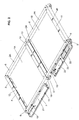
- the second rigid rectangular frame 2B is secured to the first rigid rectangular frame 2A by one or more hinges 8 so that the apparatus is selectively movable from a first extended position in which the first and second frames 2A and 2B, and thus the first and second plates 1A and 1B, are substantially coplanar and relative lateral movement between the frames is prevented, as shown in Fig. 2 , and a second, folded position as shown in Fig. 1 .
- the apparatus is readily portable.
- the first plate 1A is recessed within the first frame 2A, the uppermost surface of the first plate 1A being spaced below the uppermost surface of the first frame 2A
- the second plate 1B is recessed within the second frame 2B, the uppermost surface of the second plate 1B being spaced below the uppermost surface of the second frame 2B.
- upper or uppermost refer to the top of the apparatus as shown in the drawings, as opposed to the bottom or ground-engaging side of the apparatus.
- the apparatus of the illustrated embodiment of the invention is in its extended or unfolded position, as shown in Fig. 2 , wherein a golfer or other user stands with one foot in any location on the first force plate 1A and the other foot in any location on the second force plate 1B.
- the force plates 1A, 1B are rectangular, preferably square, in shape and are sized to accommodate a wide variety of foot sizes and stances. Where portability is desired, however, the force plates 1A, 1B are also not so large that transportation of the apparatus is difficult.
- the force plates 1A, 1B are formed of a material that is strong and rigid, remaining dimensionally stable under the forces experienced during use of the apparatus.
- the force plates 1A, 1B are preferably formed of forged aluminum for its combination of strength and low weight.
- the upper surface of each force plate 1A, 1B is preferably a non-slip surface.
- each of the frames 2A, 2B is formed of a front frame member 6, a back frame member 9, an outer side frame member 12, and an inner side member 13.
- the front and back frame members 6 and 9 are formed of hollow tubes of generally rectangular cross-section, while the outer and inner side frame members 12 and 13 are generally U- shaped, the bottom-facing side being open.
- the innermost side of the outer side frame members 12 are not shown in Figs. 1 and 2 so that the load cells 3 are visible.
- the corresponding cover portion 24 of the inner side frame 13 of frame 2B is shown in Fig. 2 .
- the frame members 6, 9, 12, and 13 are formed of any suitably strong, rigid material, and are preferably welded aluminum.
- each of the force plates 1A and 1B is mounted within the respective first and second rigid frame 2A and 2B by means of one load cell 3 mounted proximate each corner of each rectangular force plate.
- two load cells 3 are attached to the upper side of the outer side frame member 12 so as to be housed therewithin.
- each load cell 3 is secured to the frame member 12 by fasteners 26.
- Each load cell 3 is also secured to the respective force plate, plate 1B in Fig. 5 , preferably at a location proximate the corner of the plate.
- each load cell 3 is secured to the force plate 1B by fasteners 27.
- two load cells 3 are attached to upper side of the inner side frame member 13 so as to be housed therewithin.
- the force plates 1A and 1B are suspended from and mounted beneath the load cells 3, the force plates 1A and 1B are recessed within the frames 2A and 2B and are positioned as close to the surface supporting the apparatus as possible.
- the load cells 3 may be any suitable type, but are preferably binocular-style bending beam type load cells.
- the load cells 3 are selected for being rated for operation to a desired weight depending upon the application, and may typically be rated for operation to 100kg (220 lbs.) as an example.
- the mounting configuration in accordance with a preferred embodiment of the invention limits the deflection of the load cells to prevent the rating from being exceeded.
- Each of the load cells 3 is operably connected to one or more microprocessor devices 21 for receiving a signal generated by each of the load cells 3 indicative of a force applied thereto.
- the load cells 3 directly sense the respective applied forces and transmit this data to a load cell interface printed circuit board PCB 4, housed within the inner side members 13 and outer side frame members 12, and thence to the microprocessor device 21.
- the microprocessor device 21 is housed within an enclosure 7 secured to the back frame member 9 of the frame 2A. As shown, the enclosure 7 also houses an LED status indicator 11 and an embedded antenna 19 for wireless communication with, for example, a computer.
- the top cover portion of the enclosure 7 is shown in Figs. 1 and 3 , but is not shown in Fig. 2 , to aid in illustration.
- a battery enclosure may be secured, for example, to the back frame member 9 of the frame 2B.
- a rechargeable battery 22 preferably formed of individual cells, is housed within the enclosure 25 along with a charger board 23 for recharging of the battery.
- the rechargeable battery 22 allows the cable-free use of the apparatus in outdoor areas where no immediate electrical connection is possible and a standard DC power connection for inside use or to recharge the battery 22.
- a power button 10 may extend through the enclosure 25 so as to be accessible to the user.
- the top cover portion of the enclosure 25 is shown in Figs. 1 and 3 , but is not shown in Fig. 2 , to aid in illustration.
- Ground or support surface engaging feet 5 are provided in a preferred embodiment of the invention, one at the corner of each of the first and second frames 2A and 2B, as shown for example in Fig. 4 .
- one such foot 5 may be secured proximate each end of each of the front frame members 6.
- the ground-engaging feet 5 may be adjustably secured to the respective frame so that the distance between a lowermost surface of the foot and the lowermost surface of the respective frame is capable of being varied, and hence the height of the frame above the ground is adjustable at each of the feet 5. This allows a means to level the apparatus so that the plates 1A and 1B are parallel to the ground, or to cant the entire apparatus at an angle to simulate a desired playing condition.
- the feet 5 may also be provided with interchangeable anchor posts in order to place the device upon different types of surfaces, such as a sand bunker or other non-uniform surface.
- the second rigid rectangular frame 2B is secured to the first rigid rectangular frame 2A so as to prevent relative lateral movement therebetween.
- the first and second frames may be permanently secured together in an orientation such as that illustrated in Figs. 2 and 3 , such as by welding, mechanical fasteners or the like.
- the second rigid rectangular frame 2B is secured to the first rigid rectangular frame 2A by a pair of hinges 8.
- One of the hinges 8 is shown in detail in Figs. 6 and 7 .
- the hinge 8 is an assembly formed of a pair of hinge arms 16, one secured at each of the adjacent ends of the back frame members 9.
- Each of the hinge arms 16 is pivotally mounted to a hinge plate 18 acting as a floating link by means of a respective hinge pin 17.
- the hinge assemblies are configured so that the frames 2A and 2B can be folded, as shown in Fig. 1 , in the direction of their respective bottom or lower surfaces. In the extended position, shown for example in Figs.
- a hinge cover 15, shown in Figs. 1 , 3 and 4 but not in Fig. 2 is preferably provided on the rear hinge assembly to protect the wiring.
- the apparatus of the invention is able to measure forces in four directions simultaneously from each foot.
- the load cells 3 continuously collect data on forces and weight distribution and lateral motion of the front and back, and inside and outside, of each foot through displacement of the attached force plates throughout a golf swing or other sports activity.
- Such data is sent to a microcomputer PCB and transmitted via a wired or wireless connection to, for example, a computer for analysis and display in a continuous and immediate or other manner as desired, as is well known, and preferably in a form which is easy to interpret by the player and can be played back and frozen or slowed during any part of the swing for complete analysis.
- the load cells 3 When, for example, a golfer shifts position or shifts his weight while standing on the force plate apparatus of the invention in preparation for or during the backswing, pause at the top of the swing, downswing, or ball strike, the load cells 3 are able to directly sense the changes in force in a continuous manner and transmit this data to the load cell interface PCB 4 and thence to the microprocessor device 21.
- the apparatus thus provides increased sensitivity to components of the generated data, while being able to continuously measure data from four locations on each force plate.
- the sensitivity is great enough to clearly demonstrate body weight changes at the moment of impact of golf club and golf ball without the need of another method to verify this, although independent means of verifying the moment of ball strike, such as by auditory or visual (via light beam interruption), may also be employed with the apparatus of the invention.
- the dual force plate apparatus of the invention may optionally be utilized in connection with other devices to enhance the information generated and displayed.
- one or more video cameras may be employed to capture the images of the player executing the sports or other biomechanical movement.
- An accelerometer may be used to determine the three dimensional position of the apparatus.
- the dual force plate apparatus of the invention is preferably utilized with a computer-based method of capturing and analyzing data from the load cells 3 by time-stamping all data and correlating that time stamp to all processed signals generated in each moment, including relative magnitudes and positions of the forces, generating real-time weight change, video, and ball strike and trajectory data.
- the force data generated by the load cells 3 may preferably be used to provide direct tracking of the movement of the player's center of gravity throughout the sports action, including ball strike, allow real-time, slow-motion, and freeze-frame playback, and provide simultaneous and/or differential analysis of all elements of the continuum of the activity without the aid of a skilled third party.
- the apparatus of the invention thus provides a means to accurately assess sports, physical and biomechanical performance of a user in virtually any location or environment.
- the invention has been described in what is considered to represent its preferred embodiments.
- the size and shape of the projections may vary considerably.
Landscapes
- Health & Medical Sciences (AREA)
- General Health & Medical Sciences (AREA)
- Physical Education & Sports Medicine (AREA)
- Engineering & Computer Science (AREA)
- Business, Economics & Management (AREA)
- Entrepreneurship & Innovation (AREA)
- Physics & Mathematics (AREA)
- Educational Administration (AREA)
- Educational Technology (AREA)
- General Physics & Mathematics (AREA)
- Theoretical Computer Science (AREA)
- Measurement Of The Respiration, Hearing Ability, Form, And Blood Characteristics Of Living Organisms (AREA)
- Force Measurement Appropriate To Specific Purposes (AREA)
Description
- The invention relates to an apparatus for analyzing a golf swing or other biomechanical movement used repetitively in sports activity or simulated sports environmental activity setting or to assess medical and biomechanical functions of the human body, specifically to such an apparatus employing dual force plates.
- Elements and characteristics of an individual's performance during a physical, biomechanical or other sports activity, such as swinging a golf club or tennis racquet, kicking a soccer ball or football, can be analyzed to improve and optimize performance and develop better technique. This requires computerized input and analysis, since the activity during the relevant action is quick, and multiple elements are occurring nearly simultaneously, often beyond the conscious knowledge of the player involved. When all of the data is collected and analyzed, it needs to be conveyed back to the golfer or other player in an immediate and easily comprehensible way so that difficulties can be noted and corrected with repetition of the activity and comparative re-analysis.
- Sports action analysis devices, often golf swing devices with other adaptations possible, have been available for decades. In their simplest computerized form, the devices include a foot plate or plates and sensors to analyze weight shift. These have evolved in complexity as computers have evolved, and current devices outstrip their predecessors in ability to analyze the components of a golf swing or other repetitive sports move, although an optimum device has yet to be developed.
- Kretsinger (
US. Pat. No. 3,169,022 ) patented a simple device in 1965 that contains two completely independent foot plates and a row of indicator lamps in front of each that light up to show which foot bears most of the weight; the light pattern freezes at the time of ball strike. No memory of the swing is available, and swing to swing comparison is not possible. - Other later devices, such as those seen in work by Bregman (
US Pat. No. 5,118,112 ), Heisler (US Pat. No. 5,150,902 ), Cromarty (US Pat. No. 5,419,562 ), and Nesbit (US Pat. No. 6,402,635 ), feature small, independent footplates that have to be separable and able to be angled in relation to each other to accommodate the golfer's most comfortable stance. Such plates can determine the proportion of total weight on each, but cannot provide data on center of gravity because the computer does not know the position of one in relation to the other. The foot pads can also potentially slip apart during use. - Several of the devices, notably those of Heisler and Cromarty and another by Cecchin (
US Pat. No. 6,039,658 ), include two foot plates that measure total weight on each foot, but are unable to differentiate weights from different portions of the foot, such as the heel and toes or the inside versus the outside of the foot. Data from these devices is often in the form of two continuous, intertwining graphs, one from each foot's weight during the weight shifting of a swing, sometimes shown along with a video image of the golfer. Detailed interpretation of these lines and correction of the swing often requires the assistance of a skilled third party. - Advances in the art produced devices that could differentially measure the forces of the toe and heel portions of the foot. Bregman asserts this, but does not specifically teach how this information is collected. Nesbit and Mooney (
US 7,946,928 ) have cantilevered devices to measure heel and toe weights, but in each case the foot pads, like Bregman's, are separate and movable, so the center of gravity cannot be measured. - Key components of a golf swing have been chosen in the past as the focus of the devices. There has been some disagreement about which features are the most key. Bregman's and Cecchin's devices collect data from three non-identical points in the swing. Cecchin requires the activation of a timer at pre-swing, apparently by a third party, which takes measurements then and at two other timed points, which are presumed to be maximum backswing and follow-through. This raises the possibility that these measurements may be slightly off of the maximums that should be measured if the swing does not progress at the presumed speed.
- Mooney's device concentrates on six featured areas of the swing, from addressing the ball through follow-through. It compares the player's golf swing to previously-loaded typical and probable sequences and times of occurrence of feature events in golf swings. It determines the timing of the selected feature events of the player's swing by assigning probabilities of finding feature events at different time periods of the swing by comparison to when these events occur in the sample information. This also raises the possibility that the actual times when the feature events occur in the player's swing may not be exactly when predicted and measured by the pre-set timing parameters of the device.
- Measuring parameters from the entire swing, not at pre-selected and possibly not entirely accurate moments, would be optimal to give the player data from the true key points and the fullest amount of possible feedback so that he could work on smoothly correcting his deficiencies throughout his sports action and chart his overall improvement.
- In addition, a common disadvantage of the previous devices has been that they have been non-portable and connected to computers via bulky cables. None has been capable of being taken outside for simulation in the yard or at an actual driving range or golf course.
-
WO 2006/120658 A1 discloses a method and apparatus for measuring and analyzing foot related forces during a golf swing or a sports swing which is similar to a golf swing. The apparatus comprises a standing surface for the player, a communication means and a plurality of sensor means which are operable to measure force. In this prior art apparatus, the standing surface comprises two separate foot platforms, for the player's feet, produced as a single polymer moulding, with the upper surface forming a horizontal surface and with integral ribs forming rigid laterally disposed rigid elements. -
US 5,697,791 discloses devices and methods for the assessment and biofeedback training of coordination skills of a subject critical to maximizing the power and accuracy of an athletic ball-strike activity, such as golf. The device comprises a body movement sensor, a ball strike sensor, a display and a computer. The body movement sensor, in this device, includes a force plate on which both feet of the player are placed. The apparatus disclosed inWO 2009/060010 A comprises a force plate which does comprise two separate foot platforms each supported by sensor means. -
US 2007/0207873 A discloses an infrared method and apparatus for the kinematic analysis of a golfer. The apparatus may include a force platform which preferably comprises two plates positioned such that each of the golfer's feet can be placed comfortably on a separate plate. How these plates might be attached is not discussed. A foldable weighing scale is disclosed inGB 2184852 A - From the foregoing, it is apparent that improvements are needed to produce such a more complete and versatile sports action device.
- The present invention provides an apparatus for analyzing a golf swing or other biomechanical movement used repetitively in sports activity or simulated sports environmental activity setting, comprising:
- a first rectangular force plate mounted within a first rigid rectangular frame by means of at least one load cell proximate each corner of the first rectangular force plate; and
- a second rectangular force plate mounted within a second rigid rectangular frame by means of at least one load cell proximate each corner of the first rectangular force plate, the second rigid rectangular frame being secured to the first rigid rectangular frame so as to prevent relative lateral movement therebetween;
- wherein each of the load cells is operably connected to one or more microprocessor devices for receiving a signal generated by each of the load cells indicative of a force applied thereto, and
- wherein the first plate is suspended from and mounted beneath the load cells mounted to the first frame and the second plate is suspended from and mounted beneath the load cells mounted to the second frame.
- The invention, further, provides a computer-based method of capturing and analyzing data to analyze a player's golf swing or other biomechanical movement used repetitively in sports activity or simulated sports environmental activity setting, comprising:
- providing a first rectangular force plate mounted within a first rigid rectangular frame by means of at least one load cell proximate each corner of the first rectangular force plate, and a second rectangular force plate mounted within a second rigid rectangular frame by means of at least one load cell proximate each corner of the first rectangular force plate, the second rigid rectangular frame being secured to the first rigid rectangular frame so as to prevent relative lateral movement therebetween, wherein each of the load cells is operably connected to one or more microprocessor devices for receiving a signal generated by each of the load cells indicative of a force applied thereto, and wherein the first plate is suspended from and mounted beneath the load cells mounted to the first frame and the second plate is suspended from and mounted beneath the load cells mounted to the second frame;
- generating signals from each of the load cells indicative of a force applied thereto during the golf swing or other biomechanical movement, the one or more microprocessor devices receiving the signals; and
- time-stamping and correlating that time stamp to all processed signals generated in each moment, including relative magnitudes and positions of the forces, generating real-time weight change, video, and ball strike and trajectory data.
- An apparatus for analyzing a golf swing or other biomechanical movement includes first and second rectangular force plates mounted within respective first and second rigid rectangular frames by means of at least one load cell proximate each corner of each rectangular force plate. These are rectangular in the sense that each defines a rectangular outline when viewed in plan. The second rigid rectangular frame is secured to the first rigid rectangular frame so as to prevent relative lateral movement therebetween, and each of the load cells is operably connected to one or more microprocessor devices for receiving a signal generated by each of the load cells indicative of a force applied thereto.
- In a preferred embodiment, the second rigid rectangular frame is secured to the first rigid rectangular frame by one or more hinges so that the apparatus is selectively movable from a first extended position in which the first and second frames are substantially coplanar and relative lateral movement between the frames is prevented, and a second folded position. In this embodiment, the apparatus is readily portable.
- In another preferred embodiment, the first plate is recessed within the first frame, the uppermost surface of the first plate being spaced below the uppermost surface of the first frame, and the second plate is recessed within the second frame, the uppermost surface of the second plate being spaced below the uppermost surface of the second frame.
- The advantages of the invention will become readily apparent to those skilled in the art from the following detailed description of various embodiments when considered in the light of the accompanying drawings, in which:
-
Fig. 1 is a top perspective view of the dual force plate apparatus of a preferred embodiment of the invention in a folded configuration; -
Fig. 2 is a perspective view of the dual force plate apparatus ofFig. 1 in an unfolded configuration; -
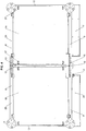
Fig. 3 is a top plan view of the dual force plate apparatus ofFig. 2 ; -
Fig. 4 is a bottom plan view of the dual force plate apparatus ofFig. 2 ; -
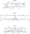
Fig. 5 is an enlarged sectional view taken along the lines A-A ofFig. 3 ; -
Fig. 6 is an enlarged sectional view taken along the lines B-B ofFig. 3 ; -
Fig. 7 is an enlarged sectional view taken along the lines C-C ofFig. 3 ; and -
Fig. 8 is a block diagram of the apparatus of the invention as part of a system for analyzing a golf swing or other biomechanical movement. - It is to be understood that the specific devices and processes illustrated in the attached drawings and described in the following description are simply exemplary embodiments of the inventive concepts defined in the appended claims. Hence, specific dimensions and other physical characteristics relating to the embodiments disclosed herein should not be considered as limiting, unless the claims expressly state otherwise.
- The apparatus of the invention is a golf or other sports action device for use outside, away from home, or wherever the user or player desires, that accurately and sensitively measures weight and forces on each foot, the heel and toe positions, and the positions of the inside and outside of each foot during a golf swing or similar activity by employing a chassis device with two independent but physically joined force plates and frames, each plate being mounted within its respective frame by at least four load cells. The portion of the frame about the first force plate is secured to the portion of the frame about the second force plate such that later movement between the two is prevented.
- Referring now to the drawings, an apparatus in accordance with a preferred embodiment of the invention is illustrated. The apparatus includes first and second
rectangular force plates rectangular frames load cell 3 proximate each corner of each rectangular force plate. In an especially preferred embodiment, theplates frames rectangular frame 2B is secured to the first rigidrectangular frame 2A so as to prevent relative lateral movement therebetween, and each of theload cells 3 is operably connected to one ormore microprocessor devices 21 for receiving a signal generated by each of theload cells 3 indicative of a force applied thereto. Theplates frames - In the illustrated preferred embodiment, the second rigid
rectangular frame 2B is secured to the first rigidrectangular frame 2A by one or more hinges 8 so that the apparatus is selectively movable from a first extended position in which the first andsecond frames second plates Fig. 2 , and a second, folded position as shown inFig. 1 . As a result, in this embodiment the apparatus is readily portable. - In a further aspect of the illustrated preferred embodiment, the
first plate 1A is recessed within thefirst frame 2A, the uppermost surface of thefirst plate 1A being spaced below the uppermost surface of thefirst frame 2A, and thesecond plate 1B is recessed within thesecond frame 2B, the uppermost surface of thesecond plate 1B being spaced below the uppermost surface of thesecond frame 2B. As used herein, upper or uppermost refer to the top of the apparatus as shown in the drawings, as opposed to the bottom or ground-engaging side of the apparatus. With recessedforce plates - In use, the apparatus of the illustrated embodiment of the invention is in its extended or unfolded position, as shown in
Fig. 2 , wherein a golfer or other user stands with one foot in any location on thefirst force plate 1A and the other foot in any location on thesecond force plate 1B. Theforce plates force plates force plates force plates force plate - The first and
second force plates rigid frames load cells 3. In the illustrated embodiment, each of theframes front frame member 6, aback frame member 9, an outerside frame member 12, and aninner side member 13. In the preferred illustrated embodiment, the front andback frame members side frame members side frame members 12 are not shown inFigs. 1 and2 so that theload cells 3 are visible. Thecorresponding cover portion 24 of theinner side frame 13 offrame 2B is shown inFig. 2 . Theframe members - In the illustrated embodiment, each of the
force plates rigid frame load cell 3 mounted proximate each corner of each rectangular force plate. In each case, twoload cells 3 are attached to the upper side of the outerside frame member 12 so as to be housed therewithin. In the illustrated embodiment, as best shown inFig. 5 , eachload cell 3 is secured to theframe member 12 byfasteners 26. Eachload cell 3 is also secured to the respective force plate,plate 1B inFig. 5 , preferably at a location proximate the corner of the plate. In the illustrated embodiment ofFig. 5 , eachload cell 3 is secured to theforce plate 1B byfasteners 27. In a like manner, and with respect to each plate, twoload cells 3 are attached to upper side of the innerside frame member 13 so as to be housed therewithin. As theforce plates load cells 3, theforce plates frames - The
load cells 3 may be any suitable type, but are preferably binocular-style bending beam type load cells. Theload cells 3 are selected for being rated for operation to a desired weight depending upon the application, and may typically be rated for operation to 100kg (220 lbs.) as an example. The mounting configuration in accordance with a preferred embodiment of the invention limits the deflection of the load cells to prevent the rating from being exceeded. - Each of the
load cells 3 is operably connected to one ormore microprocessor devices 21 for receiving a signal generated by each of theload cells 3 indicative of a force applied thereto. In the illustrated embodiment, theload cells 3 directly sense the respective applied forces and transmit this data to a load cell interface printed circuit board PCB 4, housed within theinner side members 13 and outerside frame members 12, and thence to themicroprocessor device 21. In the illustrated embodiment, themicroprocessor device 21 is housed within anenclosure 7 secured to theback frame member 9 of theframe 2A. As shown, theenclosure 7 also houses anLED status indicator 11 and an embeddedantenna 19 for wireless communication with, for example, a computer. The top cover portion of theenclosure 7 is shown inFigs. 1 and3 , but is not shown inFig. 2 , to aid in illustration. - A battery enclosure may be secured, for example, to the
back frame member 9 of theframe 2B. In the preferred illustrated embodiment, arechargeable battery 22, preferably formed of individual cells, is housed within theenclosure 25 along with acharger board 23 for recharging of the battery. Of course, therechargeable battery 22 allows the cable-free use of the apparatus in outdoor areas where no immediate electrical connection is possible and a standard DC power connection for inside use or to recharge thebattery 22. Apower button 10 may extend through theenclosure 25 so as to be accessible to the user. The top cover portion of theenclosure 25 is shown inFigs. 1 and3 , but is not shown inFig. 2 , to aid in illustration. - Ground or support
surface engaging feet 5 are provided in a preferred embodiment of the invention, one at the corner of each of the first andsecond frames Fig. 4 . As further illustrated inFig. 5 , onesuch foot 5 may be secured proximate each end of each of thefront frame members 6. The ground-engagingfeet 5 may be adjustably secured to the respective frame so that the distance between a lowermost surface of the foot and the lowermost surface of the respective frame is capable of being varied, and hence the height of the frame above the ground is adjustable at each of thefeet 5. This allows a means to level the apparatus so that theplates feet 5 may also be provided with interchangeable anchor posts in order to place the device upon different types of surfaces, such as a sand bunker or other non-uniform surface. - As noted above, the second rigid
rectangular frame 2B is secured to the first rigidrectangular frame 2A so as to prevent relative lateral movement therebetween. Thus, in an embodiment of the invention intended for use in a permanent installation (not shown), the first and second frames may be permanently secured together in an orientation such as that illustrated inFigs. 2 and3 , such as by welding, mechanical fasteners or the like. - In the readily portable apparatus of the preferred illustrated embodiment, the second rigid
rectangular frame 2B is secured to the first rigidrectangular frame 2A by a pair of hinges 8. One of the hinges 8 is shown in detail inFigs. 6 and 7 . As shown, the hinge 8 is an assembly formed of a pair ofhinge arms 16, one secured at each of the adjacent ends of theback frame members 9. Each of thehinge arms 16 is pivotally mounted to ahinge plate 18 acting as a floating link by means of arespective hinge pin 17. The hinge assemblies are configured so that theframes Fig. 1 , in the direction of their respective bottom or lower surfaces. In the extended position, shown for example inFigs. 2 ,6 and 7 , the ends of adjacent front and back frame members are abutting, cooperating with the ground or other support surface to maintain the apparatus in the extended position in which the first andsecond frames hinge cover 15, shown inFigs. 1 ,3 and4 but not inFig. 2 , is preferably provided on the rear hinge assembly to protect the wiring. - In use, the apparatus of the invention is able to measure forces in four directions simultaneously from each foot. The
load cells 3 continuously collect data on forces and weight distribution and lateral motion of the front and back, and inside and outside, of each foot through displacement of the attached force plates throughout a golf swing or other sports activity. Such data is sent to a microcomputer PCB and transmitted via a wired or wireless connection to, for example, a computer for analysis and display in a continuous and immediate or other manner as desired, as is well known, and preferably in a form which is easy to interpret by the player and can be played back and frozen or slowed during any part of the swing for complete analysis. - When, for example, a golfer shifts position or shifts his weight while standing on the force plate apparatus of the invention in preparation for or during the backswing, pause at the top of the swing, downswing, or ball strike, the
load cells 3 are able to directly sense the changes in force in a continuous manner and transmit this data to the load cell interface PCB 4 and thence to themicroprocessor device 21. The apparatus thus provides increased sensitivity to components of the generated data, while being able to continuously measure data from four locations on each force plate. The sensitivity is great enough to clearly demonstrate body weight changes at the moment of impact of golf club and golf ball without the need of another method to verify this, although independent means of verifying the moment of ball strike, such as by auditory or visual (via light beam interruption), may also be employed with the apparatus of the invention. - Further, the dual force plate apparatus of the invention may optionally be utilized in connection with other devices to enhance the information generated and displayed. Thus, one or more video cameras may be employed to capture the images of the player executing the sports or other biomechanical movement. An accelerometer may be used to determine the three dimensional position of the apparatus.
- The dual force plate apparatus of the invention is preferably utilized with a computer-based method of capturing and analyzing data from the
load cells 3 by time-stamping all data and correlating that time stamp to all processed signals generated in each moment, including relative magnitudes and positions of the forces, generating real-time weight change, video, and ball strike and trajectory data. The force data generated by theload cells 3 may preferably be used to provide direct tracking of the movement of the player's center of gravity throughout the sports action, including ball strike, allow real-time, slow-motion, and freeze-frame playback, and provide simultaneous and/or differential analysis of all elements of the continuum of the activity without the aid of a skilled third party. - The apparatus of the invention thus provides a means to accurately assess sports, physical and biomechanical performance of a user in virtually any location or environment.
- In accordance with the provisions of the patent statutes, the invention has been described in what is considered to represent its preferred embodiments. As an example, it will be appreciated that, in those embodiments in which the apparatus includes a plurality of projections, the size and shape of the projections may vary considerably.
Claims (14)
- An apparatus for analyzing a golf swing or other biomechanical movement used repetitively in sports activity or simulated sports environmental activity setting, comprising:a first rectangular force plate (1A) mounted within a first rigid rectangular frame (2A) by means of at least one load cell (3) proximate each corner of the first rectangular force plate (1A); anda second rectangular force plate (1B) mounted within a second rigid rectangular frame (2B) by means of at least one load cell (3) proximate each corner of the first rectangular force plate (1A), the second rigid rectangular frame (2B) being secured to the first rigid rectangular frame (2A) so as to prevent relative lateral movement therebetween;wherein each of the load cells (3) is operably connected to one or more microprocessor devices (21) for receiving a signal generated by each of the load cells indicative of a force applied thereto, and characterised in that the first plate (1A) is suspended from and mounted beneath the load cells (3) mounted to the first frame (2A) and the second plate (1B) is suspended from and mounted beneath the load cells mounted to the second frame (2B).
- The apparatus of claim 1, wherein the second rigid rectangular frame (2B) is secured to the first rigid rectangular frame (2A) by one or more hinges (8) so that the apparatus is selectively movable from a first extended position in which the first and second plates (1A, 1B) are substantially coplanar and relative lateral movement between the frames is prevented, and a second folded position in which transportation of the apparatus is facilitated.
- The apparatus of claim 1, wherein the first plate (1A) is recessed within the first frame (2A), the uppermost surface of the first plate (1A) being spaced below the uppermost surface of the first frame (2A), and the second plate (1B) is recessed within the second frame (2B), the uppermost surface of the second plate (1B) being spaced below the uppermost surface of the second frame (2B).
- The apparatus of claim 1, wherein the first and second frames (2A, 2B) maintain the first plate (1A) in a coplanar relationship with the second plate (1B).
- The apparatus of claim 1, further comprising at least two ground-engaging feet (5) mounted to the first frame (2A) and at least two ground-engaging feet (5) mounted to the second frame (2B).
- The apparatus of claim 5, wherein one or more of the ground-engaging feet (5) is adjustably mounted to the respective frame so that the distance between a lowermost surface of the foot and the lowermost surface of the respective frame is capable of being varied.
- The apparatus of claim 1, wherein the first and second rectangular force plates (1A, 1B) and the first and second rectangular frames (2A, 2B) are each square.
- The apparatus of claim 1, wherein the one or more microprocessor devices (21) are in communication data with a computer for analysis and display of data.
- The apparatus of claim 8, wherein the one or more microprocessor devices (21) are in communication data with the computer via a wireless connection.
- The apparatus of claim 8, further comprising a ball striker sensor which is in communication with the computer.
- The apparatus of claim 8, further comprising one or more video cameras capable of capturing images of a user of the apparatus and communicating such images to the computer.
- The apparatus of claim 8, further comprising an accelerometer for determining the three dimensional position of the apparatus and communicating such position to the computer.
- A computer-based method of capturing and analyzing data to analyse a player's golf swing or other biomechanical movement used repetitively in sports activity or simulated sports environmental activity setting, comprising:providing a first rectangular force plate (1A) mounted within a first rigid rectangular frame (2A) by means of at least one load cell (3) proximate each corner of the first rectangular force plate (1A), and a second rectangular force plate (1B) mounted within a second rigid rectangular frame (2B) by means of at least one load cell (3) proximate each corner of the first rectangular force plate (1A), the second rigid rectangular frame (2B) being secured to the first rigid rectangular frame (2A) so as to prevent relative lateral movement therebetween, wherein each of the load cells (3) is operably connected to one or more microprocessor devices (21) for receiving a signal generated by each of the load cells (3) indicative of a force applied thereto, and wherein the first plate (1A) is suspended from and mounted beneath the load cells (3) mounted to the first frame (2A) and the second plate (1B) is suspended from and mounted beneath the load cells (3) mounted to the second frame (2B);generating signals from each of the load cells (3) indicative of a force applied thereto during the golf swing or other biomechanical movement, the one or more microprocessor devices (21) receiving the signals; andtime-stamping and correlating that time stamp to all processed signals generated in each moment, including relative magnitudes and positions of the forces, generating real-time weight change, video, and ball strike and trajectory data.
- The method of claim 13, further comprising:a. directly tracking the movement of the player's center of gravity throughout the golf swing or other biomechanical movement, including at the moment of a ball strike;b. providing computer software that allows for real-time, slow-motion, and freeze-frame playback of the processed signals, andc. providing simultaneous and/or differential analysis of all elements of the continuum of the golf swing or other biomechanical movement without the aid of a skilled third party.
Applications Claiming Priority (2)
| Application Number | Priority Date | Filing Date | Title |
|---|---|---|---|
| US201161485296P | 2011-05-12 | 2011-05-12 | |
| PCT/US2012/037474 WO2012155025A1 (en) | 2011-05-12 | 2012-05-11 | Dual force plate apparatus |
Publications (3)
| Publication Number | Publication Date |
|---|---|
| EP2707107A1 EP2707107A1 (en) | 2014-03-19 |
| EP2707107A4 EP2707107A4 (en) | 2015-09-16 |
| EP2707107B1 true EP2707107B1 (en) | 2017-09-13 |
Family
ID=47139681
Family Applications (1)
| Application Number | Title | Priority Date | Filing Date |
|---|---|---|---|
| EP12782874.7A Not-in-force EP2707107B1 (en) | 2011-05-12 | 2012-05-11 | Dual force plate apparatus |
Country Status (3)
| Country | Link |
|---|---|
| US (1) | US9114300B2 (en) |
| EP (1) | EP2707107B1 (en) |
| WO (1) | WO2012155025A1 (en) |
Families Citing this family (5)
| Publication number | Priority date | Publication date | Assignee | Title |
|---|---|---|---|---|
| US12161477B1 (en) * | 2013-01-19 | 2024-12-10 | Bertec Corporation | Force measurement system |
| US11857331B1 (en) * | 2013-01-19 | 2024-01-02 | Bertec Corporation | Force measurement system |
| USD778746S1 (en) * | 2015-01-28 | 2017-02-14 | PCI Limited | Sports sensor |
| US11502972B2 (en) * | 2016-08-28 | 2022-11-15 | Vmware, Inc. | Capacity optimization in an automated resource-exchange system |
| CN107960757A (en) * | 2017-11-16 | 2018-04-27 | 常州信息职业技术学院 | A kind of portable office hold-down bar |
Citations (2)
| Publication number | Priority date | Publication date | Assignee | Title |
|---|---|---|---|---|
| GB2184852A (en) * | 1985-12-19 | 1987-07-01 | Sharp Kk | Foldable weighing scale |
| US20070207873A1 (en) * | 2006-03-01 | 2007-09-06 | Acushnet Company | IR system for kinematic analysis |
Family Cites Families (17)
| Publication number | Priority date | Publication date | Assignee | Title |
|---|---|---|---|---|
| US5118112A (en) | 1990-12-24 | 1992-06-02 | S & B Enterprises, Inc. | Golf swing balance analyzer |
| US5150902A (en) | 1991-07-09 | 1992-09-29 | Heisler Doyle J | Golfer weight distribution measurement system |
| US5419562A (en) | 1993-08-10 | 1995-05-30 | Cromarty; John I. | Method and apparatus for analyzing movements of an individual |
| US5772522A (en) * | 1994-11-23 | 1998-06-30 | United States Of Golf Association | Method of and system for analyzing a golf club swing |
| US5697791A (en) | 1994-11-29 | 1997-12-16 | Nashner; Lewis M. | Apparatus and method for assessment and biofeedback training of body coordination skills critical and ball-strike power and accuracy during athletic activitites |
| US6402635B1 (en) | 1995-02-09 | 2002-06-11 | U. S. Golf Association | Apparatus and method for measuring reaction forces and weight shifts |
| US6039658A (en) * | 1998-12-10 | 2000-03-21 | Cecchin; Euclid | Golf swing weight distribution indicator |
| US6179724B1 (en) * | 1999-02-25 | 2001-01-30 | Hong Jun Yang | Device for changing inclination angle of golf ball swing table |
| JP2002263235A (en) * | 2001-02-23 | 2002-09-17 | Amuse World Co Ltd | Golf practice device with adjustable tilt angle |
| JP2002346015A (en) * | 2001-05-28 | 2002-12-03 | Hiroaki Yoshiike | Swing diagnostic device |
| KR100489961B1 (en) * | 2003-04-01 | 2005-05-17 | (주) 골프존 | Slope Controllable Foot Plate for Golf Swing Practice Apparatus |
| IES20050288A2 (en) | 2005-05-06 | 2006-11-15 | Brian Francis Mooney | Measurement and analysis of foot related forces during a golf swing |
| US7161097B1 (en) * | 2005-10-17 | 2007-01-09 | Carmelo Gorgone | Container with a built-in scale |
| WO2007136223A1 (en) * | 2006-05-23 | 2007-11-29 | Nam Byung-Ryul | Golf swing training machine |
| CA2704653C (en) * | 2007-11-05 | 2017-06-06 | Brian Francis Mooney | Apparatus and method for analysing a golf swing |
| JP5161182B2 (en) * | 2009-09-28 | 2013-03-13 | 任天堂株式会社 | Information processing program and information processing apparatus |
| US8512142B2 (en) * | 2010-02-25 | 2013-08-20 | William B. Meldeau | Game controller having a stepping exercise platform and a sliding platform |
-
2012
- 2012-05-11 EP EP12782874.7A patent/EP2707107B1/en not_active Not-in-force
- 2012-05-11 US US13/261,777 patent/US9114300B2/en not_active Expired - Fee Related
- 2012-05-11 WO PCT/US2012/037474 patent/WO2012155025A1/en not_active Ceased
Patent Citations (2)
| Publication number | Priority date | Publication date | Assignee | Title |
|---|---|---|---|---|
| GB2184852A (en) * | 1985-12-19 | 1987-07-01 | Sharp Kk | Foldable weighing scale |
| US20070207873A1 (en) * | 2006-03-01 | 2007-09-06 | Acushnet Company | IR system for kinematic analysis |
Also Published As
| Publication number | Publication date |
|---|---|
| WO2012155025A1 (en) | 2012-11-15 |
| WO2012155025A4 (en) | 2012-12-20 |
| EP2707107A1 (en) | 2014-03-19 |
| US20140148929A1 (en) | 2014-05-29 |
| US9114300B2 (en) | 2015-08-25 |
| EP2707107A4 (en) | 2015-09-16 |
Similar Documents
| Publication | Publication Date | Title |
|---|---|---|
| US11000765B2 (en) | Method and system for athletic motion analysis and instruction | |
| US6181647B1 (en) | Vertical jump measuring device | |
| Falco et al. | Influence of the distance in a roundhouse kick's execution time and impact force in Taekwondo | |
| EP0794818B1 (en) | Apparatus and method for training with biofeedback | |
| US20110260890A1 (en) | Motion Analysis Apparatus | |
| US20160213975A1 (en) | Integrated portable device and method implementing an accelerometer for analyzing biomechanical parameters of a stride | |
| US5838638A (en) | Portable verticle jump measuring device | |
| US9114300B2 (en) | Dual force plate apparatus | |
| US20080200287A1 (en) | Trajectory detection and feedfack system for tennis | |
| Słomka et al. | Evaluation of reliability and concurrent validity of of two optoelectric systems used for recording maximum vertical jumping performance versus the gold standard | |
| Saponara | Wearable biometric performance measurement system for combat sports | |
| WO2018158552A1 (en) | System, method and markers for assessing athletic performance | |
| CN206535141U (en) | Altitude touch evaluation system is looked as far as one's eyes can see suitable for basketball and volleyball training | |
| US11193837B2 (en) | Portable strain gauge for improved impulse and peak force detection | |
| JPWO2009093631A1 (en) | Center of gravity balance judgment device | |
| WO2006062310A1 (en) | Apparatus for putting correcting and training | |
| CN110354459B (en) | A proprioceptive training interactive device for the elderly based on plantar pressure perception | |
| KR101263699B1 (en) | Trainning apparatus for boxing | |
| KR101999717B1 (en) | Golf position monitoring system using lattice type pressure sensor | |
| CN108025206A (en) | Golf shot training and calibration device | |
| GB2372220A (en) | Impact measuring target/ergometer for contact sports | |
| CN211935487U (en) | Accurate golf push rod evaluation training system | |
| TWI429471B (en) | Golf training apparatus | |
| CN102631770A (en) | Golf ball hitting simulating system | |
| JP2005253819A (en) | Center of gravity measurement device |
Legal Events
| Date | Code | Title | Description |
|---|---|---|---|
| PUAI | Public reference made under article 153(3) epc to a published international application that has entered the european phase |
Free format text: ORIGINAL CODE: 0009012 |
|
| 17P | Request for examination filed |
Effective date: 20131121 |
|
| AK | Designated contracting states |
Kind code of ref document: A1 Designated state(s): AL AT BE BG CH CY CZ DE DK EE ES FI FR GB GR HR HU IE IS IT LI LT LU LV MC MK MT NL NO PL PT RO RS SE SI SK SM TR |
|
| DAX | Request for extension of the european patent (deleted) | ||
| RA4 | Supplementary search report drawn up and despatched (corrected) |
Effective date: 20150819 |
|
| RIC1 | Information provided on ipc code assigned before grant |
Ipc: A63B 24/00 20060101ALI20150813BHEP Ipc: A63B 69/00 20060101ALN20150813BHEP Ipc: A63B 69/36 20060101AFI20150813BHEP Ipc: A63B 69/38 20060101ALN20150813BHEP Ipc: G09B 19/00 20060101ALI20150813BHEP |
|
| STAA | Information on the status of an ep patent application or granted ep patent |
Free format text: STATUS: EXAMINATION IS IN PROGRESS |
|
| 17Q | First examination report despatched |
Effective date: 20161102 |
|
| GRAP | Despatch of communication of intention to grant a patent |
Free format text: ORIGINAL CODE: EPIDOSNIGR1 |
|
| RIC1 | Information provided on ipc code assigned before grant |
Ipc: A63B 69/36 20060101AFI20170411BHEP Ipc: G09B 19/00 20060101ALI20170411BHEP Ipc: A63B 24/00 20060101ALI20170411BHEP Ipc: A63B 69/38 20060101ALN20170411BHEP Ipc: A63B 69/00 20060101ALN20170411BHEP |
|
| STAA | Information on the status of an ep patent application or granted ep patent |
Free format text: STATUS: GRANT OF PATENT IS INTENDED |
|
| RIC1 | Information provided on ipc code assigned before grant |
Ipc: A63B 69/00 20060101ALN20170502BHEP Ipc: A63B 69/36 20060101AFI20170502BHEP Ipc: A63B 69/38 20060101ALN20170502BHEP Ipc: A63B 24/00 20060101ALI20170502BHEP Ipc: G09B 19/00 20060101ALI20170502BHEP |
|
| INTG | Intention to grant announced |
Effective date: 20170518 |
|
| GRAS | Grant fee paid |
Free format text: ORIGINAL CODE: EPIDOSNIGR3 |
|
| GRAA | (expected) grant |
Free format text: ORIGINAL CODE: 0009210 |
|
| STAA | Information on the status of an ep patent application or granted ep patent |
Free format text: STATUS: THE PATENT HAS BEEN GRANTED |
|
| AK | Designated contracting states |
Kind code of ref document: B1 Designated state(s): AL AT BE BG CH CY CZ DE DK EE ES FI FR GB GR HR HU IE IS IT LI LT LU LV MC MK MT NL NO PL PT RO RS SE SI SK SM TR |
|
| REG | Reference to a national code |
Ref country code: GB Ref legal event code: FG4D |
|
| REG | Reference to a national code |
Ref country code: CH Ref legal event code: EP |
|
| REG | Reference to a national code |
Ref country code: IE Ref legal event code: FG4D |
|
| REG | Reference to a national code |
Ref country code: AT Ref legal event code: REF Ref document number: 927580 Country of ref document: AT Kind code of ref document: T Effective date: 20171015 |
|
| REG | Reference to a national code |
Ref country code: DE Ref legal event code: R096 Ref document number: 602012037339 Country of ref document: DE |
|
| REG | Reference to a national code |
Ref country code: NL Ref legal event code: MP Effective date: 20170913 |
|
| REG | Reference to a national code |
Ref country code: LT Ref legal event code: MG4D |
|
| PG25 | Lapsed in a contracting state [announced via postgrant information from national office to epo] |
Ref country code: HR Free format text: LAPSE BECAUSE OF FAILURE TO SUBMIT A TRANSLATION OF THE DESCRIPTION OR TO PAY THE FEE WITHIN THE PRESCRIBED TIME-LIMIT Effective date: 20170913 Ref country code: SE Free format text: LAPSE BECAUSE OF FAILURE TO SUBMIT A TRANSLATION OF THE DESCRIPTION OR TO PAY THE FEE WITHIN THE PRESCRIBED TIME-LIMIT Effective date: 20170913 Ref country code: FI Free format text: LAPSE BECAUSE OF FAILURE TO SUBMIT A TRANSLATION OF THE DESCRIPTION OR TO PAY THE FEE WITHIN THE PRESCRIBED TIME-LIMIT Effective date: 20170913 Ref country code: NO Free format text: LAPSE BECAUSE OF FAILURE TO SUBMIT A TRANSLATION OF THE DESCRIPTION OR TO PAY THE FEE WITHIN THE PRESCRIBED TIME-LIMIT Effective date: 20171213 Ref country code: LT Free format text: LAPSE BECAUSE OF FAILURE TO SUBMIT A TRANSLATION OF THE DESCRIPTION OR TO PAY THE FEE WITHIN THE PRESCRIBED TIME-LIMIT Effective date: 20170913 |
|
| REG | Reference to a national code |
Ref country code: AT Ref legal event code: MK05 Ref document number: 927580 Country of ref document: AT Kind code of ref document: T Effective date: 20170913 |
|
| PG25 | Lapsed in a contracting state [announced via postgrant information from national office to epo] |
Ref country code: RS Free format text: LAPSE BECAUSE OF FAILURE TO SUBMIT A TRANSLATION OF THE DESCRIPTION OR TO PAY THE FEE WITHIN THE PRESCRIBED TIME-LIMIT Effective date: 20170913 Ref country code: LV Free format text: LAPSE BECAUSE OF FAILURE TO SUBMIT A TRANSLATION OF THE DESCRIPTION OR TO PAY THE FEE WITHIN THE PRESCRIBED TIME-LIMIT Effective date: 20170913 Ref country code: GR Free format text: LAPSE BECAUSE OF FAILURE TO SUBMIT A TRANSLATION OF THE DESCRIPTION OR TO PAY THE FEE WITHIN THE PRESCRIBED TIME-LIMIT Effective date: 20171214 Ref country code: BG Free format text: LAPSE BECAUSE OF FAILURE TO SUBMIT A TRANSLATION OF THE DESCRIPTION OR TO PAY THE FEE WITHIN THE PRESCRIBED TIME-LIMIT Effective date: 20171213 Ref country code: ES Free format text: LAPSE BECAUSE OF FAILURE TO SUBMIT A TRANSLATION OF THE DESCRIPTION OR TO PAY THE FEE WITHIN THE PRESCRIBED TIME-LIMIT Effective date: 20170913 |
|
| PG25 | Lapsed in a contracting state [announced via postgrant information from national office to epo] |
Ref country code: NL Free format text: LAPSE BECAUSE OF FAILURE TO SUBMIT A TRANSLATION OF THE DESCRIPTION OR TO PAY THE FEE WITHIN THE PRESCRIBED TIME-LIMIT Effective date: 20170913 |
|
| PG25 | Lapsed in a contracting state [announced via postgrant information from national office to epo] |
Ref country code: CZ Free format text: LAPSE BECAUSE OF FAILURE TO SUBMIT A TRANSLATION OF THE DESCRIPTION OR TO PAY THE FEE WITHIN THE PRESCRIBED TIME-LIMIT Effective date: 20170913 Ref country code: RO Free format text: LAPSE BECAUSE OF FAILURE TO SUBMIT A TRANSLATION OF THE DESCRIPTION OR TO PAY THE FEE WITHIN THE PRESCRIBED TIME-LIMIT Effective date: 20170913 Ref country code: PL Free format text: LAPSE BECAUSE OF FAILURE TO SUBMIT A TRANSLATION OF THE DESCRIPTION OR TO PAY THE FEE WITHIN THE PRESCRIBED TIME-LIMIT Effective date: 20170913 |
|
| REG | Reference to a national code |
Ref country code: FR Ref legal event code: PLFP Year of fee payment: 7 |
|
| PG25 | Lapsed in a contracting state [announced via postgrant information from national office to epo] |
Ref country code: EE Free format text: LAPSE BECAUSE OF FAILURE TO SUBMIT A TRANSLATION OF THE DESCRIPTION OR TO PAY THE FEE WITHIN THE PRESCRIBED TIME-LIMIT Effective date: 20170913 Ref country code: AT Free format text: LAPSE BECAUSE OF FAILURE TO SUBMIT A TRANSLATION OF THE DESCRIPTION OR TO PAY THE FEE WITHIN THE PRESCRIBED TIME-LIMIT Effective date: 20170913 Ref country code: SK Free format text: LAPSE BECAUSE OF FAILURE TO SUBMIT A TRANSLATION OF THE DESCRIPTION OR TO PAY THE FEE WITHIN THE PRESCRIBED TIME-LIMIT Effective date: 20170913 Ref country code: IS Free format text: LAPSE BECAUSE OF FAILURE TO SUBMIT A TRANSLATION OF THE DESCRIPTION OR TO PAY THE FEE WITHIN THE PRESCRIBED TIME-LIMIT Effective date: 20180113 Ref country code: SM Free format text: LAPSE BECAUSE OF FAILURE TO SUBMIT A TRANSLATION OF THE DESCRIPTION OR TO PAY THE FEE WITHIN THE PRESCRIBED TIME-LIMIT Effective date: 20170913 Ref country code: IT Free format text: LAPSE BECAUSE OF FAILURE TO SUBMIT A TRANSLATION OF THE DESCRIPTION OR TO PAY THE FEE WITHIN THE PRESCRIBED TIME-LIMIT Effective date: 20170913 |
|
| REG | Reference to a national code |
Ref country code: DE Ref legal event code: R097 Ref document number: 602012037339 Country of ref document: DE |
|
| PLBE | No opposition filed within time limit |
Free format text: ORIGINAL CODE: 0009261 |
|
| STAA | Information on the status of an ep patent application or granted ep patent |
Free format text: STATUS: NO OPPOSITION FILED WITHIN TIME LIMIT |
|
| PG25 | Lapsed in a contracting state [announced via postgrant information from national office to epo] |
Ref country code: DK Free format text: LAPSE BECAUSE OF FAILURE TO SUBMIT A TRANSLATION OF THE DESCRIPTION OR TO PAY THE FEE WITHIN THE PRESCRIBED TIME-LIMIT Effective date: 20170913 |
|
| 26N | No opposition filed |
Effective date: 20180614 |
|
| PG25 | Lapsed in a contracting state [announced via postgrant information from national office to epo] |
Ref country code: SI Free format text: LAPSE BECAUSE OF FAILURE TO SUBMIT A TRANSLATION OF THE DESCRIPTION OR TO PAY THE FEE WITHIN THE PRESCRIBED TIME-LIMIT Effective date: 20170913 |
|
| REG | Reference to a national code |
Ref country code: CH Ref legal event code: PL |
|
| REG | Reference to a national code |
Ref country code: BE Ref legal event code: MM Effective date: 20180531 |
|
| PG25 | Lapsed in a contracting state [announced via postgrant information from national office to epo] |
Ref country code: MC Free format text: LAPSE BECAUSE OF FAILURE TO SUBMIT A TRANSLATION OF THE DESCRIPTION OR TO PAY THE FEE WITHIN THE PRESCRIBED TIME-LIMIT Effective date: 20170913 |
|
| REG | Reference to a national code |
Ref country code: IE Ref legal event code: MM4A |
|
| PG25 | Lapsed in a contracting state [announced via postgrant information from national office to epo] |
Ref country code: CH Free format text: LAPSE BECAUSE OF NON-PAYMENT OF DUE FEES Effective date: 20180531 Ref country code: LI Free format text: LAPSE BECAUSE OF NON-PAYMENT OF DUE FEES Effective date: 20180531 |
|
| PG25 | Lapsed in a contracting state [announced via postgrant information from national office to epo] |
Ref country code: LU Free format text: LAPSE BECAUSE OF NON-PAYMENT OF DUE FEES Effective date: 20180511 |
|
| PG25 | Lapsed in a contracting state [announced via postgrant information from national office to epo] |
Ref country code: IE Free format text: LAPSE BECAUSE OF NON-PAYMENT OF DUE FEES Effective date: 20180511 |
|
| PG25 | Lapsed in a contracting state [announced via postgrant information from national office to epo] |
Ref country code: BE Free format text: LAPSE BECAUSE OF NON-PAYMENT OF DUE FEES Effective date: 20180531 |
|
| PGFP | Annual fee paid to national office [announced via postgrant information from national office to epo] |
Ref country code: DE Payment date: 20190530 Year of fee payment: 8 |
|
| PGFP | Annual fee paid to national office [announced via postgrant information from national office to epo] |
Ref country code: FR Payment date: 20190527 Year of fee payment: 8 |
|
| PGFP | Annual fee paid to national office [announced via postgrant information from national office to epo] |
Ref country code: GB Payment date: 20190528 Year of fee payment: 8 |
|
| PG25 | Lapsed in a contracting state [announced via postgrant information from national office to epo] |
Ref country code: MT Free format text: LAPSE BECAUSE OF NON-PAYMENT OF DUE FEES Effective date: 20180511 |
|
| PG25 | Lapsed in a contracting state [announced via postgrant information from national office to epo] |
Ref country code: TR Free format text: LAPSE BECAUSE OF FAILURE TO SUBMIT A TRANSLATION OF THE DESCRIPTION OR TO PAY THE FEE WITHIN THE PRESCRIBED TIME-LIMIT Effective date: 20170913 |
|
| PG25 | Lapsed in a contracting state [announced via postgrant information from national office to epo] |
Ref country code: HU Free format text: LAPSE BECAUSE OF FAILURE TO SUBMIT A TRANSLATION OF THE DESCRIPTION OR TO PAY THE FEE WITHIN THE PRESCRIBED TIME-LIMIT; INVALID AB INITIO Effective date: 20120511 Ref country code: PT Free format text: LAPSE BECAUSE OF FAILURE TO SUBMIT A TRANSLATION OF THE DESCRIPTION OR TO PAY THE FEE WITHIN THE PRESCRIBED TIME-LIMIT Effective date: 20170913 |
|
| PG25 | Lapsed in a contracting state [announced via postgrant information from national office to epo] |
Ref country code: MK Free format text: LAPSE BECAUSE OF NON-PAYMENT OF DUE FEES Effective date: 20170913 Ref country code: CY Free format text: LAPSE BECAUSE OF FAILURE TO SUBMIT A TRANSLATION OF THE DESCRIPTION OR TO PAY THE FEE WITHIN THE PRESCRIBED TIME-LIMIT Effective date: 20170913 |
|
| PG25 | Lapsed in a contracting state [announced via postgrant information from national office to epo] |
Ref country code: AL Free format text: LAPSE BECAUSE OF FAILURE TO SUBMIT A TRANSLATION OF THE DESCRIPTION OR TO PAY THE FEE WITHIN THE PRESCRIBED TIME-LIMIT Effective date: 20170913 |
|
| REG | Reference to a national code |
Ref country code: DE Ref legal event code: R119 Ref document number: 602012037339 Country of ref document: DE |
|
| GBPC | Gb: european patent ceased through non-payment of renewal fee |
Effective date: 20200511 |
|
| PG25 | Lapsed in a contracting state [announced via postgrant information from national office to epo] |
Ref country code: FR Free format text: LAPSE BECAUSE OF NON-PAYMENT OF DUE FEES Effective date: 20200531 Ref country code: GB Free format text: LAPSE BECAUSE OF NON-PAYMENT OF DUE FEES Effective date: 20200511 |
|
| PG25 | Lapsed in a contracting state [announced via postgrant information from national office to epo] |
Ref country code: DE Free format text: LAPSE BECAUSE OF NON-PAYMENT OF DUE FEES Effective date: 20201201 |