EP2706743A2 - Image reading apparatus and image forminng apparatus having the same - Google Patents
Image reading apparatus and image forminng apparatus having the same Download PDFInfo
- Publication number
- EP2706743A2 EP2706743A2 EP13183576.1A EP13183576A EP2706743A2 EP 2706743 A2 EP2706743 A2 EP 2706743A2 EP 13183576 A EP13183576 A EP 13183576A EP 2706743 A2 EP2706743 A2 EP 2706743A2
- Authority
- EP
- European Patent Office
- Prior art keywords
- light
- carriage
- heat dissipating
- scanning direction
- document sheet
- Prior art date
- Legal status (The legal status is an assumption and is not a legal conclusion. Google has not performed a legal analysis and makes no representation as to the accuracy of the status listed.)
- Granted
Links
- 238000001514 detection method Methods 0.000 claims abstract description 63
- 238000003384 imaging method Methods 0.000 description 7
- 230000000694 effects Effects 0.000 description 4
- XAGFODPZIPBFFR-UHFFFAOYSA-N aluminium Chemical compound [Al] XAGFODPZIPBFFR-UHFFFAOYSA-N 0.000 description 3
- 229910052782 aluminium Inorganic materials 0.000 description 3
- 239000004411 aluminium Substances 0.000 description 3
- 238000004512 die casting Methods 0.000 description 3
- 239000000463 material Substances 0.000 description 3
- 238000000034 method Methods 0.000 description 3
- 239000000758 substrate Substances 0.000 description 3
- 238000004140 cleaning Methods 0.000 description 2
- 230000017525 heat dissipation Effects 0.000 description 2
- 230000007246 mechanism Effects 0.000 description 2
- 230000003287 optical effect Effects 0.000 description 2
- 230000002093 peripheral effect Effects 0.000 description 2
- 230000003068 static effect Effects 0.000 description 2
- FGRBYDKOBBBPOI-UHFFFAOYSA-N 10,10-dioxo-2-[4-(N-phenylanilino)phenyl]thioxanthen-9-one Chemical compound O=C1c2ccccc2S(=O)(=O)c2ccc(cc12)-c1ccc(cc1)N(c1ccccc1)c1ccccc1 FGRBYDKOBBBPOI-UHFFFAOYSA-N 0.000 description 1
- 239000004925 Acrylic resin Substances 0.000 description 1
- 229920000178 Acrylic resin Polymers 0.000 description 1
- 230000002238 attenuated effect Effects 0.000 description 1
- 230000008901 benefit Effects 0.000 description 1
- 230000005540 biological transmission Effects 0.000 description 1
- 230000015572 biosynthetic process Effects 0.000 description 1
- 230000000903 blocking effect Effects 0.000 description 1
- 239000011521 glass Substances 0.000 description 1
- 238000005286 illumination Methods 0.000 description 1
- 238000010348 incorporation Methods 0.000 description 1
- 230000008569 process Effects 0.000 description 1
- 230000009467 reduction Effects 0.000 description 1
- 230000000630 rising effect Effects 0.000 description 1
- 239000012780 transparent material Substances 0.000 description 1
- 229910052724 xenon Inorganic materials 0.000 description 1
- FHNFHKCVQCLJFQ-UHFFFAOYSA-N xenon atom Chemical compound [Xe] FHNFHKCVQCLJFQ-UHFFFAOYSA-N 0.000 description 1
Images


Classifications
-
- H—ELECTRICITY
- H04—ELECTRIC COMMUNICATION TECHNIQUE
- H04N—PICTORIAL COMMUNICATION, e.g. TELEVISION
- H04N1/00—Scanning, transmission or reproduction of documents or the like, e.g. facsimile transmission; Details thereof
- H04N1/00519—Constructional details not otherwise provided for, e.g. housings, covers
-
- H—ELECTRICITY
- H04—ELECTRIC COMMUNICATION TECHNIQUE
- H04N—PICTORIAL COMMUNICATION, e.g. TELEVISION
- H04N1/00—Scanning, transmission or reproduction of documents or the like, e.g. facsimile transmission; Details thereof
Definitions
- the present disclosure relates to image reading apparatuses for use in copying machines, facsimile machines, multifunctional peripherals incorporating the entirety or some of functions of these machines, image scanners, or the like, and image forming apparatuses including the image reading apparatuses.
- An image forming apparatus forms an electrostatic latent image on a surface of a photosensitive member by causing an image reading apparatus to read an image, on a document sheet, to be copied, and applying laser light to the photosensitive member that is an image carrier, based on document sheet image data having been read.
- the image reading apparatus applies light from a linearly-arranged light source to the document sheet placed on a document sheet table, and receives light reflected by the document sheet, via a mirror or the like, by a photoelectric converting portion.
- the photoelectric converting portion converts the received light to an electrical signal.
- the document sheet image data is obtained.
- a light source that lights a document sheet a xenon lamp, a light-emitting diode, or the like is used. In recent years, reduction in size and power-saving are required for lighting devices, and image reading apparatuses that use light-emitting diodes as light sources are known.
- lighting devices that use a mode in which multiple light-emitting diodes are disposed along a longitudinal direction (the primary scanning direction) of the lighting device, and lighting devices that use a mode in which light of one light-emitting diode disposed at an end portion in the longitudinal direction is diffused by a light guide member over the entirety of a region in the longitudinal direction, are used.
- cost is low, and mounting operation is relatively easily performed.
- an amount of light with which a document sheet is lit tends to become insufficient, and an amount of light from the lighting device needs to be increased.
- an electric current to be applied to the light-emitting diode needs to be increased.
- increase of an electric current to be applied causes increase in heat emission from the light-emitting diode. If heat emission from the light-emitting diode increases, in a case where document sheet images are read continuously over a long time period, the temperature of the light-emitting diode rises, and the light-emitting diode is thus likely to be damaged or an amount of emitted light is likely to be reduced.
- An associated technique for dissipating heat from a light-emitting diode and reducing rising of temperature in the light-emitting diode is known.
- a light-emitting diode is mounted onto a substrate, and the substrate having the light-emitting diode mounted thereon is joined to a heat dissipating member made of aluminium, through a heat transmission member.
- a plurality of heat-dissipating fins are disposed on an outer surface of the heat dissipating member, thereby dissipating heat generated in the light-emitting diode.
- a plurality of heat dissipating fins are disposed in the heat dissipating member, or the size of the heat dissipating member itself is increased. Therefore, the size of the lighting device having the heat dissipating member provided therein is increased. Further, in the image reading apparatus, in order to perform reading by scanning a document sheet, a carriage having the lighting device is moved in a secondary scanning direction, and when the reading the document sheet is completed, the carriage is returned to an initial position.
- the initial position of the carriage is detected by a position detecting portion having a photointerrupter or the like, and a driving motor for the carriage is stopped based on the detection result.
- a detection member that moves in the secondary scanning direction according to the carriage shuttling, is necessary.
- An image reading apparatus includes a document sheet table, a first carriage, a photoelectric converting portion, and a position detecting portion.
- the document sheet table has a top surface on which a document sheet is placed.
- the first carriage has a lighting portion which applies light from a light source so as to diffuse the light toward the document sheet table in a primary scanning direction, and the first carriage can shuttle in a secondary scanning direction orthogonal to the primary scanning direction.
- the photoelectric converting portion receives, as image light, light obtained by the light applied by the lighting portion being reflected by an image surface of the document sheet, and converts the received image light to an electrical signal.
- the position detecting portion detects an initial position in shuttling of the first carriage.
- the light source is disposed at an end portion, in the primary scanning direction, of the lighting portion.
- the lighting portion includes: a light guide member on which the light from the light source is incident, and which guides the incident light in the primary scanning direction and applies the light to the document sheet table; and a heat dissipating member that dissipates heat generated in the light source.
- the position detecting portion includes: a light emitter that emits light; a light receiver that receives the light emitted from the light emitter; and a detection member that moves in the secondary scanning direction along with the shuttling of the first carriage, in order to detect the initial position of the first carriage.
- the detection member is formed as a flat plate that is integrated with the heat dissipating member and extends in the secondary scanning direction.
- An image forming apparatus includes an image reading apparatus, and an image forming portion that forms an image on a recording medium.
- the image reading apparatus includes a document sheet table, a first carriage, a photoelectric converting portion, and a position detecting portion.
- the document sheet table has a top surface on which a document sheet is placed.
- the first carriage has a lighting portion which applies light from a light source so as to diffuse the light toward the document sheet table in a primary scanning direction, and the first carriage can shuttle in a secondary scanning direction orthogonal to the primary scanning direction.
- the photoelectric converting portion receives, as image light, light obtained by the light applied by the lighting portion being reflected by an image surface of the document sheet, and converts the received image light to an electrical signal.
- the position detecting portion detects an initial position in shuttling of the first carriage.
- the light source is disposed at an end portion, in the primary scanning direction, of the lighting portion.
- the lighting portion includes: a light guide member on which the light from the light source is incident, and which guides the incident light in the primary scanning direction and applies the light to the document sheet table; and a heat dissipating member that dissipates heat generated in the light source.
- the position detecting portion includes: a light emitter that emits light; a light receiver that receives the light emitted from the light emitter; and a detection member that moves in the secondary scanning direction along with the shuttling of the first carriage, in order to detect the initial position of the first carriage.
- the detection member is formed as a flat plate that is integrated with the heat dissipating member and extends in the secondary scanning direction.
- FIG. 1 is a cross-sectional view of an image forming apparatus having an image reading apparatus according to a first embodiment of the present disclosure.
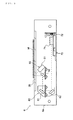
- FIG. 2 is a cross-sectional view of the image reading apparatus shown in FIG. 1 .
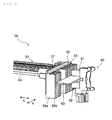
- FIG. 3 is a perspective view illustrating configurations of a lighting portion and a position detecting portion of the image reading apparatus shown in FIG. 1 .
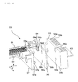
- FIG. 4 is an exploded perspective view of the lighting portion and the position detecting portion shown in FIG. 3 .
- FIG. 5 is a perspective view illustrating configurations of a heat dissipating member and a detection member according to a second embodiment of the present disclosure.
- FIG. 1 is a cross-sectional view illustrating a configuration of an image forming apparatus having an image reading apparatus according to an embodiment of the present disclosure.
- An image forming apparatus 1 includes: a sheet feed portion 2 disposed in the lower portion of the apparatus 1; a sheet conveying portion 3 disposed lateral to the sheet feed portion 2; an image forming portion 4 disposed above the sheet conveying portion 3; a fixing device 5 disposed closer to the discharge side in a sheet conveying direction than the image forming portion 4 is; an image reading apparatus 6 disposed above the image forming portion 4 and the fixing device 5; and a document sheet conveying device 18.
- the document sheet conveying device 18 includes a document sheet feed tray 18a in which document sheets on which characters and images, such as figures, to be copied are drawn, are stacked.
- the document sheet conveying device 18 separates the document sheets one by one from the document sheet feed tray 18a, to convey the separated document sheet to a document sheet table 35 of the image reading apparatus 6.
- Below the document sheet conveying device 18, the document sheet reading device 6 is disposed.
- a document sheet conveyed onto the document sheet table 35 from the document sheet conveying device 18, or a document sheet placed on the document sheet table 35 is scanned by using light, to read an image of the document sheet.
- the sheet feed portion 2 includes a plurality of sheet feed cassettes 7 in which sheets 9 that are recording mediums are stored.
- the sheet feed portion 2 feeds the sheets 9 one by one from a selected one of the plurality of sheet feed cassettes 7 to the sheet conveying portion 3 according to rotation of a sheet feed roller 8.
- the sheet 9 having been fed to the sheet conveying portion 3 is conveyed via a sheet conveying path 10 of the sheet conveying portion 3 toward the image forming portion 4.
- the image forming portion 4 forms a toner image on the sheet 9 by electrophotographic process.
- the image forming portion 4 includes a photosensitive member 11 supported so as to be rotatable in the direction indicated by an arrow in FIG. 1 , a charging portion 12, an exposure portion 13, a developing portion 14, a transfer portion 15, a cleaning portion 16, and a static eliminating portion 17 that are disposed around the photosensitive member 11 along the rotation direction thereof.
- the charging portion 12 includes a charged wire to which a high voltage is applied.
- the charging portion 12 applies a predetermined potential to a surface of the photosensitive member 11 by corona discharge from the charged wire. Thus, the surface of the photosensitive member 11 is uniformly charged.
- the electrostatic latent image on the surface of the photosensitive member 11 is developed by the developing portion 14, to form a toner image on the surface of the photosensitive member 11.
- the toner image is transferred, by the transfer portion 15, to the sheet 9 supplied between the photosensitive member 11 and the transfer portion 15.
- the sheet 9 on which the toner image has been transferred is conveyed toward the fixing device 5 disposed downstream of the image forming portion 4 in the sheet conveying direction.
- the fixing device 5 the sheet 9 is heated and pressurized, and the toner image is fused and fixed onto the sheet 9.
- the sheet 9 on which the toner image has been fixed is discharged by a pair of discharge rollers 20 to a discharge tray 21.
- toner left on the surface of the photosensitive member 11 is removed by the cleaning portion 16. Further, residual charge on the surface of the photosensitive member 11 is eliminated by the static eliminating portion 17. The photosensitive member 11 is charged again by the charging portion 12, and an image is formed in the same manner as described above.
- FIG. 2 is a cross-sectional view illustrating a configuration of the image reading apparatus 6.
- the image reading apparatus 6 includes the document sheet table 35 such as a contact glass, a first carriage 50 disposed below the document sheet table 35, the second carriage 60 disposed to the left of the first carriage 50, and a photoelectric converting portion 70 disposed to the right of the second carriage 60.
- the first carriage 50 and the second carriage 60 are connected to not-illustrated scanning mechanism portions, respectively. Each of the scanning mechanism portions moves at a predetermined rate in the left-right direction in FIG. 2 . Thus, a document sheet M on the document sheet table 35 is exposed to light and scanned, to read the entirety of the surface of the document sheet M.
- the first carriage 50 includes a lighting portion 51 and a first mirror 52.
- the lighting portion 51 applies illumination light to the document sheet M on the document sheet table 35 so as to diffuse the light in the primary scanning direction (the front surface-back surface direction of the sheet of FIG. 2 ).
- the first mirror 52 reflects light reflected by the document sheet M toward the second carriage 60.
- the first mirror 52 is tilted by 45 degrees relative to the vertical direction and is held by the first carriage 50.
- the second carriage 60 includes a second mirror 61 and a third mirror 62.
- the second mirror 61 is disposed so as to oppose the first mirror 52 in the horizontal direction.
- the second mirror 61 is tilted by 45 degrees relative to the vertical direction, in the same direction as the direction in which the first mirror 52 is tilted, and is held by the second carriage 60.
- the third mirror 62 is disposed below the second mirror 61 so as to oppose the second mirror 61.
- the third mirror 62 is tilted by 45 degrees relative to the vertical direction, in the direction opposite to the direction in which the second mirror 61 is tilted, and is held by the second carriage 60.
- the light reflected by the first mirror 52 of the first carriage 50 travels in the horizontal direction, to reach the second mirror 61, and the light reflected by the second mirror 61 travels downward, to reach the third mirror 62, and the light reflected by the third mirror 62 travels in the horizontal direction, to be guided to the photoelectric converting portion 70.
- the photoelectric converting portion 70 includes an imaging lens 71 and an image sensor 72 disposed to the right of the imaging lens 71.
- the photoelectric converting portion 70 is fixed to an apparatus body 6a of the image reading apparatus 6.
- the imaging lens 71 focuses, on the image sensor 72, light that has been reflected by the document sheet M and incident through the third mirror 62.
- the image sensor 72 has imaging elements, such as a CCD, arrayed in the primary scanning direction (the front surface-back surface direction of the sheet of FIG. 2 ), and converts, to an electrical signal, an optical image of the document sheet M formed by the imaging lens 71.
- the document sheet M is lit by the lighting portion 51 of the first carriage 50, and the first carriage 50 moves rightward (in the secondary scanning direction) at a predetermined rate from an initial position shown in FIG. 2 to an end position that is a right end portion of the document sheet M. Further, the second carriage 60 moves rightward (in the secondary scanning direction) from the initial position shown in FIG. 2 at half the rate at which the first carriage 50 moves, in conjunction with the first carriage 50.
- the first carriage 50 moves from the initial position to the end position, thereby reading the document sheet image on the entirety of a surface of the document sheet M.
- the first carriage 50 and the second carriage 60 are returned to the initial positions, respectively.
- the first carriage 50 and the second carriage 60 are held at the initial positions shown in FIG. 2 .
- the document sheet M is conveyed onto the document sheet table 35 by the document sheet conveying device 18 (see FIG. 1 ).
- the document sheet image on the document sheet M is sequentially read at a position, of the document sheet table 35, which opposes the initial positions, to form image data.
- FIG. 3 and FIG. 4 illustrate configurations of the lighting portion 51 of the first carriage 50, and a position detecting portion 80 that detects an initial position of the first carriage 50.
- FIG. 3 is a perspective view illustrating the configurations of the lighting portion 51 and the position detecting portion 80.
- FIG. 4 is an exploded perspective view of components of the lighting portion 51 and the position detecting portion 80.
- FIG. 3 and FIG. 4 illustrate a configuration of a right end portion of the first carriage 50, and illustration of a light emitter 81 and a light receiver 82 of the position detecting portion 80 is omitted in FIG. 4 .
- the lighting portion 51 of the first carriage 50 includes a light guide member 53, a light-emitting diode 54 (see FIG. 4 ) that is a light source, a heat dissipating member 55, a base plate 56 to which the light-emitting diode 54 is mounted, and a frame 57 that is a framework for the first carriage 50.
- a detection member 83 is provided in the first carriage 50.
- the position detecting portion 80 that detects an initial position of the first carriage 50 is constructed by the detection member 83, the light emitter 81, and the light receiver 82.
- the light guide member 53 extends leftward in FIG. 3 . However, the light-emitting diode 54, the heat dissipating member 55, and the position detecting portion 80 are not provided in the left end portion of the first carriage 50.
- the light guide member 53 extends in the primary scanning direction X so as to have a dimension corresponding to the length, in the width direction, of the document sheet table 35 (see FIG. 2 ), and is formed in a predetermined shape by an optically transparent material such as an acrylic resin.
- the light guide member 53 is mounted to the frame 57 (the first carriage 50) such that a light receiving surface 53a formed on the end surface, in the primary scanning direction X, of the light guide member 53 opposes the light-emitting diode 54.
- Light emitted from the light-emitting diode 54 is incident on the light receiving surface 53a of the light guide member 53.
- the light incident on the light receiving surface 53a is guided while being diffused in the light guide member 53 in the primary scanning direction X.
- the light diffused in the primary scanning direction X is applied to the document sheet table 35, to light the document sheet M on the document sheet table 35.
- the light-emitting diode 54 includes a light emitting element 54a that emits light, and a substrate 54b having a circuit pattern formed thereon.
- the light emitting element 54a is disposed so as to oppose the light receiving surface 53a of the light guide member 53, and emits light toward the light receiving surface 53a.
- electric components such as a connector are mounted on the base plate 56.
- the light-emitting diode 54 is mounted to a mounting surface 56a of the base plate 56.
- the base plate 56 is formed in a rectangular shape by a material having a relatively high heat conductivity.
- the heat dissipating member 55 is mounted on a mounting surface 56b of the base plate 56 on a side opposite to the mounting surface 56a side.
- the heat dissipating member 55 is used to dissipate heat generated in the light-emitting diode 54.
- the heat dissipating member 55 is formed by a material, such as aluminium, having a high heat dissipation effect.
- the heat dissipating member 55 has a mounting surface 55c having an area almost equal to an area of the mounting surface 56a of the base plate 56.
- a mounting hole 55e through which the heat dissipating member 55 is mounted to the frame 57 via the base plate 56 is formed.
- a mounting hole 56d is formed so as to oppose the mounting hole 55e of the heat dissipating member 55.
- a screw hole (invisible in FIG. 4 ) is formed so as to oppose the mounting hole 55e of the heat dissipating member 55.
- a positioning hole 55d is formed in the mounting surface 55c of the heat dissipating member 55 in order to position the heat dissipating member 55 and the base plate 56 relative to the frame 57 and mount them to the frame 57.
- a positioning hole 56c is formed in the mounting surface 56a of the base plate 56.
- a projection 57b that fits into the positioning hole 55d and the positioning hole 56c is formed on a mounting surface 57a of the frame 57.
- a plurality of heat dissipating fins 55a are formed on a surface of the heat dissipating member 55 on a side opposite to the mounting surface 55c side.
- a plurality of flat plates are vertically disposed and aligned at predetermined intervals along the secondary scanning direction Y, thereby forming the heat dissipating fins 55a.
- the detection member 83 is formed so as to be integrated with the heat dissipating member 55.
- the detection member 83 has a depth dimension almost equal to the length, in the secondary scanning direction Y, of the heat dissipating member 55, and is formed as a flat plate that extends in the secondary scanning direction Y. Further, the detection member 83 is a flat plate having surfaces that are flat in the up-down direction (the up-down direction in FIG. 4 ).
- the detection member 83 is disposed so as to oppose the projection end portions 55b of the heat dissipating fins 55a, and is formed so as to be integrated with the heat dissipating member 55.
- the heat dissipating member 55 and the detection member 83 are formed, by die casting, so as to be integrated with each other. For example, a mold for die casting is separated into an upper mold and a lower mold at a position corresponding to the detection member 83. Cores that can be laterally moved are used for portions corresponding to the mounting hole 55e and the positioning hole 55d of the mounting surface 55c. Thus, the heat dissipating member 55 and the detection member 83 are formed. After the forming, surfaces of the heat dissipating member 55 and the detection member 83 are treated with black alumite.
- the detection member 83 When the detection member 83 is formed in a flat-plate-like shape, and is integrated with the heat dissipating member 55, heat generated in the light-emitting diode 54 is advantageously dissipated from the detection member 83 as well as the heat dissipating member 55.
- the detection member 83 is further used, together with the light emitter 81 and the light receiver 82 (see FIG. 3 ), to detect an initial position of the first carriage 50. In this configuration, the image reading apparatus 6 for which increase in apparatus size is suppressed, can be obtained.
- the light emitter 81 and the light receiver 82 oppose each other in the up-down direction and are supported by the apparatus body 6a (see FIG. 2 ).
- the light emitter 81 emits light toward the light receiver 82, and the light receiver 82 outputs a signal according to whether the light emitted from the light emitter 81 is received or blocked.
- the light emitter 81 and the light receiver 82 are disposed so as to oppose the detection member 83 when the first carriage 50 is at the initial position shown in FIG. 2 .
- the first carriage 50 shuttles in the secondary scanning direction Y, and then returns to the initial position, the light emitted from the light emitter 81 is blocked by the detection member 83, and the light receiver 82 does not receive light emitted from the light emitter 81.
- the initial position of the first carriage 50 is detected. Specifically, by the first carriage 50 moving in the secondary scanning direction Y, light emitted from the light emitter 81 is blocked by the end surface, in the secondary scanning direction Y, of the detection member 83, so that the light receiver 82 outputs an off signal.
- the surface of the detection member 83 is treated so as to have black color, the light emitted from the light emitter 81 is assuredly blocked by the detection member 83. Therefore, the first carriage 50 is less likely to stop at a position deviated from the initial position. Further, since the surface of the detection member 83 is treated so as to have black color, heat dissipating efficiency is enhanced. Therefore, both the surface of the detection member 83 and the surface of the heat dissipating member 55 are treated so as to have black color, thereby more advantageously dissipating heat generated in the light-emitting diode 54.
- FIG. 5 is a perspective view illustrating configurations of a heat dissipating member 55 and a detection member 83 according to a second embodiment of the present disclosure.
- a plurality of heat dissipating fins 55a are aligned in up-down direction. Difference in configurations of the heat dissipating member 55 and the detection member 83 from those of the first embodiment will be mainly described.
- description of the same components as those of the first embodiment is not given.
- a plurality of heat dissipating fins 55a are formed in the heat dissipating member 55.
- a plurality of flat plates are aligned at predetermined intervals along the up-down direction (the up-down direction in FIG. 5 ) to form the heat dissipating fins 55a.
- one of the flat plates is formed so as to project more greatly than projection end portions 55b of the other flat plates.
- the flat plate located at the center of the plurality of flat plates aligned in up-down direction projects most greatly, and the most greatly projecting flat plate is used as the detection member 83.
- the flat plate used as the detection member 83 may be a flat plate located above or below the flat plate located at the center.
- the heat dissipating member 55 and the detection member 83 are formed into a predetermined shape, by die casting, from a material, such as aluminium, having a high heat dissipation effect, and the surfaces thereof are treated with black alumite.
- the detection member 83 is provided so as to be movable between the light emitter 81 and the light receiver 82 (see FIG. 3 ) that are disposed in the up-down direction so as to oppose each other.
- the detection member 83 When the first carriage 50 is at an initial position (see FIG. 2 ), light emitted from the light emitter 81 is blocked by the detection member 83. Due to this blocking, the light receiver 82 does not receive light emitted from the light emitter 81, thereby detecting the initial position of the first carriage 50.
- the detection member 83 When the detection member 83 is formed in a flat-plate-like shape, and is integrated with the heat dissipating member 55, heat generated in the light-emitting diode 54 is advantageously dissipated from the detection member 83 as well as the heat dissipating member 55, and the detection member 83 is further used, together with the light emitter 81 and the light receiver 82 (see FIG. 3 ), to detect the initial position of the first carriage 50. In this configuration, the image reading apparatus 6 for which increase in apparatus size is suppressed, can be obtained.
- the surface of the detection member 83 is treated so as to have black color, light emitted from the light emitter 81 is assuredly blocked by the detection member 83, and the first carriage 50 is less likely to stop at a position deviated from the initial position. Further, since the surface of the detection member 83 is treated so as to have black color, heat dissipating efficiency is enhanced. Therefore, both the surface of the detection member 83 and the surface of the heat dissipating member 55 are treated so as to have black color, thereby more advantageously dissipating heat generated in the light-emitting diode 54.
- the heat dissipating member 55 and the position detecting portion 80 of each of the first and the second embodiments are applicable to the image reading apparatus 6 that includes the first carriage 50 and the second carriage 60 that move in the secondary scanning direction Y, and the photoelectric converting portion 70 disposed below the first carriage 50.
- the image reading apparatus 6 having this configuration a light path for a document sheet image from the second carriage 60 toward the photoelectric converting portion 70 is formed below the first carriage 50. Therefore, if the position detecting portion 80 including a detection member is disposed, on a lower surface of the first carriage 50, in a primary scanning range for reading, a problem may arise that the light path is interrupted by the detection member or the like.
- the image reading apparatus 6 having the configuration described above is advantageous in that, as in the embodiments, the detection member 83 is disposed in one end portion in the primary scanning direction X, and is further integrated with the heat dissipating member 55.
- the embodiments may be applied to image reading apparatuses other than the image reading apparatus 6 having the configuration described above.
- the embodiments may be applied to an image reading apparatus in which the first carriage 50 includes the lighting portion 51 and the photoelectric converting portion 70, and, when the first carriage 50 moves in the secondary scanning direction Y, the photoelectric converting portion 70 moves together with the lighting portion 51, whereby the document sheet M is scanned and a document sheet image is read.
- the heat dissipating member 55 is disposed in one end portion in the primary scanning direction.
- the present disclosure is not limited thereto.
- the heat dissipating members 55 may be disposed in both end portions in the primary scanning direction X, and the detection member 83 may be integrated with one of the heat dissipating members 55. Also in this case, the same effects as in the embodiments described above are obtained
- the position detecting portion 80 is a photointerrupter in which the light emitter 81 and the light receiver 82 oppose each other.
- the position detecting portion 80 may have a structure in which, when the detection member 83 passes by the light emitter 81, light emitted from the light emitter 81 is reflected by the detection member 83, and the light receiver 82 receives the reflected light, thereby detecting a position.
- the detection member 83 extends in the secondary scanning direction Y, is formed as a flat plate having surfaces that are flat in the primary scanning direction X, opposes the projection end portions 55b of the heat dissipating fins 55a, and integrated with the heat dissipating member 55.
- the detection member 83 may be disposed above or below the heat dissipating fins 55a, and integrated with the heat dissipating member 55. Also in this case, the same effects as in the embodiments described above are obtained.
- the frame 57 includes the projection 57b that fits into the positioning hole 55d and the positioning hole 56c, in order to position the heat dissipating member 55 and the base plate 56 relative to the frame 57 and mount them to the frame 57.
- the present disclosure is not limited thereto.
- the heat dissipating member 55 may have a positioning projection formed therein, and the base plate 56 and the frame 57 may have formed therein positioning holes into which the positioning projection is fitted.
- the present disclosure is applicable to image reading apparatuses that are used for copying machines, facsimile machines, multifunctional peripherals incorporating the entirety or some of functions of these machines, image scanners, and the like, and that scan and read document sheets, and is applicable to image forming apparatuses including the image reading apparatuses.
Landscapes
- Engineering & Computer Science (AREA)
- Multimedia (AREA)
- Signal Processing (AREA)
- Facsimile Scanning Arrangements (AREA)
- Light Sources And Details Of Projection-Printing Devices (AREA)
- Image Input (AREA)
- Optical Systems Of Projection Type Copiers (AREA)
Abstract
Description
- This application is based upon and claims the benefit of priority from the corresponding Japanese Patent Application No.
2012-199325 filed on September 11, 2012 - The present disclosure relates to image reading apparatuses for use in copying machines, facsimile machines, multifunctional peripherals incorporating the entirety or some of functions of these machines, image scanners, or the like, and image forming apparatuses including the image reading apparatuses.
- An image forming apparatus forms an electrostatic latent image on a surface of a photosensitive member by causing an image reading apparatus to read an image, on a document sheet, to be copied, and applying laser light to the photosensitive member that is an image carrier, based on document sheet image data having been read. The image reading apparatus applies light from a linearly-arranged light source to the document sheet placed on a document sheet table, and receives light reflected by the document sheet, via a mirror or the like, by a photoelectric converting portion. The photoelectric converting portion converts the received light to an electrical signal. Thus, the document sheet image data is obtained. As a light source that lights a document sheet, a xenon lamp, a light-emitting diode, or the like is used. In recent years, reduction in size and power-saving are required for lighting devices, and image reading apparatuses that use light-emitting diodes as light sources are known.
- As lighting devices using light-emitting diodes, lighting devices that use a mode in which multiple light-emitting diodes are disposed along a longitudinal direction (the primary scanning direction) of the lighting device, and lighting devices that use a mode in which light of one light-emitting diode disposed at an end portion in the longitudinal direction is diffused by a light guide member over the entirety of a region in the longitudinal direction, are used. In the mode in which one light-emitting diode is disposed at an end portion in the longitudinal direction, cost is low, and mounting operation is relatively easily performed. However, in this mode, an amount of light with which a document sheet is lit tends to become insufficient, and an amount of light from the lighting device needs to be increased. In order to increase an amount of light from the lighting device, a light-emitting diode that has an enhanced brightness is necessary. Therefore, an electric current to be applied to the light-emitting diode needs to be increased. In this case, increase of an electric current to be applied causes increase in heat emission from the light-emitting diode. If heat emission from the light-emitting diode increases, in a case where document sheet images are read continuously over a long time period, the temperature of the light-emitting diode rises, and the light-emitting diode is thus likely to be damaged or an amount of emitted light is likely to be reduced. Further, heat is transmitted to optical components, such as a mirror or a lens, near the light-emitting diode, an image sensor of a photoelectric converting portion, or the like. Therefore, a performance for an image formation on the photoelectric converting portion is likely to be degraded.
- An associated technique for dissipating heat from a light-emitting diode and reducing rising of temperature in the light-emitting diode, is known. For example, in a publicly known image reading apparatus, a light-emitting diode is mounted onto a substrate, and the substrate having the light-emitting diode mounted thereon is joined to a heat dissipating member made of aluminium, through a heat transmission member. A plurality of heat-dissipating fins are disposed on an outer surface of the heat dissipating member, thereby dissipating heat generated in the light-emitting diode.
- In general, in order to enhance a heat dissipating efficiency of the heat dissipating member, a plurality of heat dissipating fins are disposed in the heat dissipating member, or the size of the heat dissipating member itself is increased. Therefore, the size of the lighting device having the heat dissipating member provided therein is increased. Further, in the image reading apparatus, in order to perform reading by scanning a document sheet, a carriage having the lighting device is moved in a secondary scanning direction, and when the reading the document sheet is completed, the carriage is returned to an initial position. In order to stop the carriage at the initial position, the initial position of the carriage is detected by a position detecting portion having a photointerrupter or the like, and a driving motor for the carriage is stopped based on the detection result. In order to detect the initial position of the carriage by means of the position detecting portion, a detection member that moves in the secondary scanning direction according to the carriage shuttling, is necessary. When the detection member is provided on the outer circumferential portion of the carriage as well as the heat dissipating member is provided in the lighting device as described above, the size of the image reading apparatus is further increased.
- An image reading apparatus according to one aspect of the present disclosure includes a document sheet table, a first carriage, a photoelectric converting portion, and a position detecting portion. The document sheet table has a top surface on which a document sheet is placed. The first carriage has a lighting portion which applies light from a light source so as to diffuse the light toward the document sheet table in a primary scanning direction, and the first carriage can shuttle in a secondary scanning direction orthogonal to the primary scanning direction. The photoelectric converting portion receives, as image light, light obtained by the light applied by the lighting portion being reflected by an image surface of the document sheet, and converts the received image light to an electrical signal. The position detecting portion detects an initial position in shuttling of the first carriage. The light source is disposed at an end portion, in the primary scanning direction, of the lighting portion. The lighting portion includes: a light guide member on which the light from the light source is incident, and which guides the incident light in the primary scanning direction and applies the light to the document sheet table; and a heat dissipating member that dissipates heat generated in the light source. The position detecting portion includes: a light emitter that emits light; a light receiver that receives the light emitted from the light emitter; and a detection member that moves in the secondary scanning direction along with the shuttling of the first carriage, in order to detect the initial position of the first carriage. The detection member is formed as a flat plate that is integrated with the heat dissipating member and extends in the secondary scanning direction.
- An image forming apparatus according to another aspect of the present disclosure includes an image reading apparatus, and an image forming portion that forms an image on a recording medium. The image reading apparatus includes a document sheet table, a first carriage, a photoelectric converting portion, and a position detecting portion. The document sheet table has a top surface on which a document sheet is placed. The first carriage has a lighting portion which applies light from a light source so as to diffuse the light toward the document sheet table in a primary scanning direction, and the first carriage can shuttle in a secondary scanning direction orthogonal to the primary scanning direction. The photoelectric converting portion receives, as image light, light obtained by the light applied by the lighting portion being reflected by an image surface of the document sheet, and converts the received image light to an electrical signal. The position detecting portion detects an initial position in shuttling of the first carriage. The light source is disposed at an end portion, in the primary scanning direction, of the lighting portion. The lighting portion includes: a light guide member on which the light from the light source is incident, and which guides the incident light in the primary scanning direction and applies the light to the document sheet table; and a heat dissipating member that dissipates heat generated in the light source. The position detecting portion includes: a light emitter that emits light; a light receiver that receives the light emitted from the light emitter; and a detection member that moves in the secondary scanning direction along with the shuttling of the first carriage, in order to detect the initial position of the first carriage. The detection member is formed as a flat plate that is integrated with the heat dissipating member and extends in the secondary scanning direction.
- This Summary is provided to introduce a selection of concepts in a simplified form that are further described below in the Detailed Description with reference where appropriate to the accompanying drawings. This Summary is not intended to identify key features or essential features of the claimed subject matter, nor is it intended to be used to limit the scope of the claimed subject matter. Furthermore, the claimed subject matter is not limited to implementations that solve any or all disadvantages noted in any part of this disclosure.
-
FIG. 1 is a cross-sectional view of an image forming apparatus having an image reading apparatus according to a first embodiment of the present disclosure. -
FIG. 2 is a cross-sectional view of the image reading apparatus shown inFIG. 1 . -
FIG. 3 is a perspective view illustrating configurations of a lighting portion and a position detecting portion of the image reading apparatus shown inFIG. 1 . -
FIG. 4 is an exploded perspective view of the lighting portion and the position detecting portion shown inFIG. 3 . -
FIG. 5 is a perspective view illustrating configurations of a heat dissipating member and a detection member according to a second embodiment of the present disclosure. - Hereinafter, embodiments of the present disclosure will be described with reference to the drawings. The present disclosure is not limited to the embodiments described below. Further, usages of the present disclosure, terms used herein, and the like are not limited to those described herein.
-
FIG. 1 is a cross-sectional view illustrating a configuration of an image forming apparatus having an image reading apparatus according to an embodiment of the present disclosure. Animage forming apparatus 1 includes: asheet feed portion 2 disposed in the lower portion of theapparatus 1; asheet conveying portion 3 disposed lateral to thesheet feed portion 2; animage forming portion 4 disposed above thesheet conveying portion 3; afixing device 5 disposed closer to the discharge side in a sheet conveying direction than theimage forming portion 4 is; animage reading apparatus 6 disposed above theimage forming portion 4 and thefixing device 5; and a documentsheet conveying device 18. - The document
sheet conveying device 18 includes a documentsheet feed tray 18a in which document sheets on which characters and images, such as figures, to be copied are drawn, are stacked. The documentsheet conveying device 18 separates the document sheets one by one from the documentsheet feed tray 18a, to convey the separated document sheet to a document sheet table 35 of theimage reading apparatus 6. Below the documentsheet conveying device 18, the documentsheet reading device 6 is disposed. In the documentsheet reading device 6, a document sheet conveyed onto the document sheet table 35 from the documentsheet conveying device 18, or a document sheet placed on the document sheet table 35 is scanned by using light, to read an image of the document sheet. - The
sheet feed portion 2 includes a plurality ofsheet feed cassettes 7 in whichsheets 9 that are recording mediums are stored. Thesheet feed portion 2 feeds thesheets 9 one by one from a selected one of the plurality ofsheet feed cassettes 7 to thesheet conveying portion 3 according to rotation of asheet feed roller 8. - The
sheet 9 having been fed to thesheet conveying portion 3 is conveyed via asheet conveying path 10 of thesheet conveying portion 3 toward theimage forming portion 4. Theimage forming portion 4 forms a toner image on thesheet 9 by electrophotographic process. Theimage forming portion 4 includes aphotosensitive member 11 supported so as to be rotatable in the direction indicated by an arrow inFIG. 1 , a chargingportion 12, anexposure portion 13, a developingportion 14, atransfer portion 15, a cleaningportion 16, and a static eliminatingportion 17 that are disposed around thephotosensitive member 11 along the rotation direction thereof. - The charging
portion 12 includes a charged wire to which a high voltage is applied. The chargingportion 12 applies a predetermined potential to a surface of thephotosensitive member 11 by corona discharge from the charged wire. Thus, the surface of thephotosensitive member 11 is uniformly charged. - Light based on image data of a document sheet read by the
image reading apparatus 6 is applied, from theexposure portion 13, to thephotosensitive member 11 having been charged. Thus, potential on the surface of thephotosensitive member 11 is selectively attenuated, thereby forming an electrostatic latent image on the surface of thephotosensitive member 11. - Next, the electrostatic latent image on the surface of the
photosensitive member 11 is developed by the developingportion 14, to form a toner image on the surface of thephotosensitive member 11. The toner image is transferred, by thetransfer portion 15, to thesheet 9 supplied between thephotosensitive member 11 and thetransfer portion 15. - The
sheet 9 on which the toner image has been transferred is conveyed toward the fixingdevice 5 disposed downstream of theimage forming portion 4 in the sheet conveying direction. In thefixing device 5, thesheet 9 is heated and pressurized, and the toner image is fused and fixed onto thesheet 9. Next, thesheet 9 on which the toner image has been fixed is discharged by a pair ofdischarge rollers 20 to adischarge tray 21. - After the toner image has been transferred to the
sheet 9 by thetransfer portion 15, toner left on the surface of thephotosensitive member 11 is removed by the cleaningportion 16. Further, residual charge on the surface of thephotosensitive member 11 is eliminated by the static eliminatingportion 17. Thephotosensitive member 11 is charged again by the chargingportion 12, and an image is formed in the same manner as described above. -
FIG. 2 is a cross-sectional view illustrating a configuration of theimage reading apparatus 6. Theimage reading apparatus 6 includes the document sheet table 35 such as a contact glass, afirst carriage 50 disposed below the document sheet table 35, thesecond carriage 60 disposed to the left of thefirst carriage 50, and a photoelectric convertingportion 70 disposed to the right of thesecond carriage 60. - The
first carriage 50 and thesecond carriage 60 are connected to not-illustrated scanning mechanism portions, respectively. Each of the scanning mechanism portions moves at a predetermined rate in the left-right direction inFIG. 2 . Thus, a document sheet M on the document sheet table 35 is exposed to light and scanned, to read the entirety of the surface of the document sheet M. - The
first carriage 50 includes alighting portion 51 and afirst mirror 52. Thelighting portion 51 applies illumination light to the document sheet M on the document sheet table 35 so as to diffuse the light in the primary scanning direction (the front surface-back surface direction of the sheet ofFIG. 2 ). Thefirst mirror 52 reflects light reflected by the document sheet M toward thesecond carriage 60. Thefirst mirror 52 is tilted by 45 degrees relative to the vertical direction and is held by thefirst carriage 50. - The
second carriage 60 includes asecond mirror 61 and athird mirror 62. Thesecond mirror 61 is disposed so as to oppose thefirst mirror 52 in the horizontal direction. Thesecond mirror 61 is tilted by 45 degrees relative to the vertical direction, in the same direction as the direction in which thefirst mirror 52 is tilted, and is held by thesecond carriage 60. Thethird mirror 62 is disposed below thesecond mirror 61 so as to oppose thesecond mirror 61. Thethird mirror 62 is tilted by 45 degrees relative to the vertical direction, in the direction opposite to the direction in which thesecond mirror 61 is tilted, and is held by thesecond carriage 60. - Therefore, the light reflected by the
first mirror 52 of thefirst carriage 50 travels in the horizontal direction, to reach thesecond mirror 61, and the light reflected by thesecond mirror 61 travels downward, to reach thethird mirror 62, and the light reflected by thethird mirror 62 travels in the horizontal direction, to be guided to the photoelectric convertingportion 70. - The photoelectric converting
portion 70 includes an imaging lens 71 and animage sensor 72 disposed to the right of the imaging lens 71. The photoelectric convertingportion 70 is fixed to anapparatus body 6a of theimage reading apparatus 6. The imaging lens 71 focuses, on theimage sensor 72, light that has been reflected by the document sheet M and incident through thethird mirror 62. Theimage sensor 72 has imaging elements, such as a CCD, arrayed in the primary scanning direction (the front surface-back surface direction of the sheet ofFIG. 2 ), and converts, to an electrical signal, an optical image of the document sheet M formed by the imaging lens 71. - In a case where a document sheet image is read in a state where the document sheet M is placed on the document sheet table 35, the document sheet M is lit by the
lighting portion 51 of thefirst carriage 50, and thefirst carriage 50 moves rightward (in the secondary scanning direction) at a predetermined rate from an initial position shown inFIG. 2 to an end position that is a right end portion of the document sheet M. Further, thesecond carriage 60 moves rightward (in the secondary scanning direction) from the initial position shown inFIG. 2 at half the rate at which thefirst carriage 50 moves, in conjunction with thefirst carriage 50. At the positions, in the secondary scanning direction, on which each carriage moves, light reflected by the document sheet M due to light illuminated by thelighting portion 51 of thefirst carriage 50 is reflected by thefirst mirror 52 toward thesecond mirror 61 of thesecond carriage 60. In thesecond carriage 60, the light reflected by the document sheet M is reflected by thesecond mirror 61 toward thethird mirror 62. The reflected light is further guided from thethird mirror 62 to the imaging lens 71 of the photoelectric convertingportion 70, and is focused, as an image, on theimage sensor 72 by the imaging lens 71. A document sheet image formed on theimage sensor 72 is converted to an electrical signal by a not-illustrated image processing circuit, to form image data. Thus, while the document sheet M is being lit by thelighting portion 51, thefirst carriage 50 moves from the initial position to the end position, thereby reading the document sheet image on the entirety of a surface of the document sheet M. When reading of the document sheet image is completed, thefirst carriage 50 and thesecond carriage 60 are returned to the initial positions, respectively. - In a case where an image on the document sheet M is read by a sheet through method, the
first carriage 50 and thesecond carriage 60 are held at the initial positions shown inFIG. 2 . The document sheet M is conveyed onto the document sheet table 35 by the document sheet conveying device 18 (seeFIG. 1 ). Thus, the document sheet image on the document sheet M is sequentially read at a position, of the document sheet table 35, which opposes the initial positions, to form image data. -
FIG. 3 andFIG. 4 illustrate configurations of thelighting portion 51 of thefirst carriage 50, and aposition detecting portion 80 that detects an initial position of thefirst carriage 50.FIG. 3 is a perspective view illustrating the configurations of thelighting portion 51 and theposition detecting portion 80.FIG. 4 is an exploded perspective view of components of thelighting portion 51 and theposition detecting portion 80.FIG. 3 andFIG. 4 illustrate a configuration of a right end portion of thefirst carriage 50, and illustration of alight emitter 81 and alight receiver 82 of theposition detecting portion 80 is omitted inFIG. 4 . - As shown in
FIG. 3 , thelighting portion 51 of thefirst carriage 50 includes alight guide member 53, a light-emitting diode 54 (seeFIG. 4 ) that is a light source, aheat dissipating member 55, abase plate 56 to which the light-emittingdiode 54 is mounted, and aframe 57 that is a framework for thefirst carriage 50. Further, adetection member 83 is provided in thefirst carriage 50. Theposition detecting portion 80 that detects an initial position of thefirst carriage 50 is constructed by thedetection member 83, thelight emitter 81, and thelight receiver 82. Thelight guide member 53 extends leftward inFIG. 3 . However, the light-emittingdiode 54, theheat dissipating member 55, and theposition detecting portion 80 are not provided in the left end portion of thefirst carriage 50. - As shown in
FIG. 4 , thelight guide member 53 extends in the primary scanning direction X so as to have a dimension corresponding to the length, in the width direction, of the document sheet table 35 (seeFIG. 2 ), and is formed in a predetermined shape by an optically transparent material such as an acrylic resin. Thelight guide member 53 is mounted to the frame 57 (the first carriage 50) such that alight receiving surface 53a formed on the end surface, in the primary scanning direction X, of thelight guide member 53 opposes the light-emittingdiode 54. Light emitted from the light-emittingdiode 54 is incident on thelight receiving surface 53a of thelight guide member 53. The light incident on thelight receiving surface 53a is guided while being diffused in thelight guide member 53 in the primary scanning direction X. The light diffused in the primary scanning direction X is applied to the document sheet table 35, to light the document sheet M on the document sheet table 35. - The light-emitting
diode 54 includes alight emitting element 54a that emits light, and asubstrate 54b having a circuit pattern formed thereon. Thelight emitting element 54a is disposed so as to oppose thelight receiving surface 53a of thelight guide member 53, and emits light toward thelight receiving surface 53a. On thebase plate 56, electric components such as a connector are mounted. The light-emittingdiode 54 is mounted to a mountingsurface 56a of thebase plate 56. Thebase plate 56 is formed in a rectangular shape by a material having a relatively high heat conductivity. On a mountingsurface 56b of thebase plate 56 on a side opposite to the mountingsurface 56a side, theheat dissipating member 55 is mounted. - The
heat dissipating member 55 is used to dissipate heat generated in the light-emittingdiode 54. Theheat dissipating member 55 is formed by a material, such as aluminium, having a high heat dissipation effect. Theheat dissipating member 55 has a mountingsurface 55c having an area almost equal to an area of the mountingsurface 56a of thebase plate 56. - In the mounting
surface 55c, a mountinghole 55e through which theheat dissipating member 55 is mounted to theframe 57 via thebase plate 56 is formed. Further, in thebase plate 56, a mountinghole 56d is formed so as to oppose the mountinghole 55e of theheat dissipating member 55. Further, in theframe 57, a screw hole (invisible inFIG. 4 ) is formed so as to oppose the mountinghole 55e of theheat dissipating member 55. Further, apositioning hole 55d is formed in the mountingsurface 55c of theheat dissipating member 55 in order to position theheat dissipating member 55 and thebase plate 56 relative to theframe 57 and mount them to theframe 57. Further, apositioning hole 56c is formed in the mountingsurface 56a of thebase plate 56. On the other hand, aprojection 57b that fits into thepositioning hole 55d and thepositioning hole 56c is formed on a mountingsurface 57a of theframe 57. - After the
projection 57b is fitted into thepositioning hole 55d and thepositioning hole 56c, and theheat dissipating member 55 and thebase plate 56 are positioned relative to theframe 57, a screw is screwed into the screw hole of theframe 57 through the mountinghole 55e and the mountinghole 56d. Thus, theheat dissipating member 55 and thebase plate 56 are accurately mounted to theframe 57. Further, the mountingsurface 55c of theheat dissipating member 55 is mounted in close contact with the mountingsurface 56b of thebase plate 56. Therefore, heat generated in the light-emittingdiode 54 is transmitted to theheat dissipating member 55 via thebase plate 56, and advantageously dissipated from theheat dissipating member 55. - On a surface of the
heat dissipating member 55 on a side opposite to the mountingsurface 55c side, a plurality ofheat dissipating fins 55a are formed. A plurality of flat plates are vertically disposed and aligned at predetermined intervals along the secondary scanning direction Y, thereby forming theheat dissipating fins 55a. When heat is dissipated from theheat dissipating member 55, hot air flowing from the lower side toward the upper side is generated around theheat dissipating member 55. Therefore, when the flat plates are aligned at predetermined intervals along the secondary scanning direction Y, upward airflow is generated in spaces between the adjacent flat plates due to the hot air. Thus, heat transmitted to theheat dissipating member 55 is dissipated with an enhanced efficiency. - At
projection end portions 55b of theheat dissipating fins 55a, thedetection member 83 is formed so as to be integrated with theheat dissipating member 55. Thedetection member 83 has a depth dimension almost equal to the length, in the secondary scanning direction Y, of theheat dissipating member 55, and is formed as a flat plate that extends in the secondary scanning direction Y. Further, thedetection member 83 is a flat plate having surfaces that are flat in the up-down direction (the up-down direction inFIG. 4 ). Therefore, in a state where spaces are each formed between the flat plates of adjacent ones of the plurality ofheat dissipating fins 55a, thedetection member 83 is disposed so as to oppose theprojection end portions 55b of theheat dissipating fins 55a, and is formed so as to be integrated with theheat dissipating member 55. Theheat dissipating member 55 and thedetection member 83 are formed, by die casting, so as to be integrated with each other. For example, a mold for die casting is separated into an upper mold and a lower mold at a position corresponding to thedetection member 83. Cores that can be laterally moved are used for portions corresponding to the mountinghole 55e and thepositioning hole 55d of the mountingsurface 55c. Thus, theheat dissipating member 55 and thedetection member 83 are formed. After the forming, surfaces of theheat dissipating member 55 and thedetection member 83 are treated with black alumite. - When the
detection member 83 is formed in a flat-plate-like shape, and is integrated with theheat dissipating member 55, heat generated in the light-emittingdiode 54 is advantageously dissipated from thedetection member 83 as well as theheat dissipating member 55. Thedetection member 83 is further used, together with thelight emitter 81 and the light receiver 82 (seeFIG. 3 ), to detect an initial position of thefirst carriage 50. In this configuration, theimage reading apparatus 6 for which increase in apparatus size is suppressed, can be obtained. Namely, even when thedetection member 83 used to detect an initial position for document sheet reading is provided as well as theheat dissipating member 55 used to dissipate heat generated in the light-emittingdiode 54 as a light source for lighting is provided, increase in sizes of theimage reading apparatus 6 andimage forming apparatus 1 can be suppressed. - As shown in
FIG. 3 , thelight emitter 81 and thelight receiver 82 oppose each other in the up-down direction and are supported by theapparatus body 6a (seeFIG. 2 ). Thelight emitter 81 emits light toward thelight receiver 82, and thelight receiver 82 outputs a signal according to whether the light emitted from thelight emitter 81 is received or blocked. Thelight emitter 81 and thelight receiver 82 are disposed so as to oppose thedetection member 83 when thefirst carriage 50 is at the initial position shown inFIG. 2 . - Therefore, when the
first carriage 50 shuttles in the secondary scanning direction Y, and then returns to the initial position, the light emitted from thelight emitter 81 is blocked by thedetection member 83, and thelight receiver 82 does not receive light emitted from thelight emitter 81. Thus, the initial position of thefirst carriage 50 is detected. Specifically, by thefirst carriage 50 moving in the secondary scanning direction Y, light emitted from thelight emitter 81 is blocked by the end surface, in the secondary scanning direction Y, of thedetection member 83, so that thelight receiver 82 outputs an off signal. When a predetermined time period has elapsed after the output of the off signal, namely, when thedetection member 83 is positioned relative to thelight receiver 82 such that almost the center, in the depth direction (the secondary scanning direction), of thedetection member 83 is on thelight receiver 82, driving of a motor (not-shown) that drives thefirst carriage 50 is stopped, thereby holding thefirst carriage 50 at the initial position. - Since the surface of the
detection member 83 is treated so as to have black color, the light emitted from thelight emitter 81 is assuredly blocked by thedetection member 83. Therefore, thefirst carriage 50 is less likely to stop at a position deviated from the initial position. Further, since the surface of thedetection member 83 is treated so as to have black color, heat dissipating efficiency is enhanced. Therefore, both the surface of thedetection member 83 and the surface of theheat dissipating member 55 are treated so as to have black color, thereby more advantageously dissipating heat generated in the light-emittingdiode 54. -
FIG. 5 is a perspective view illustrating configurations of aheat dissipating member 55 and adetection member 83 according to a second embodiment of the present disclosure. In the second embodiment, a plurality ofheat dissipating fins 55a are aligned in up-down direction. Difference in configurations of theheat dissipating member 55 and thedetection member 83 from those of the first embodiment will be mainly described. Hereinafter, description of the same components as those of the first embodiment is not given. - In the
heat dissipating member 55, a plurality ofheat dissipating fins 55a are formed. A plurality of flat plates are aligned at predetermined intervals along the up-down direction (the up-down direction inFIG. 5 ) to form theheat dissipating fins 55a. When the first carriage 50 (seeFIG. 2 ) moves in the secondary scanning direction Y, airflow in the secondary scanning direction Y is generated, around theheat dissipating member 55, relative to spaces in which thefirst carriage 50 moves, due to movement of thefirst carriage 50. Therefore, when the flat plates are aligned at predetermined intervals along the up-down direction, airflow in the secondary scanning direction Y is generated in spaces between the adjacent flat plates, thereby dissipating heat transmitted to theheat dissipating member 55 with an enhanced efficiency. - In the plurality of
heat dissipating fins 55a, one of the flat plates is formed so as to project more greatly thanprojection end portions 55b of the other flat plates. In the present embodiment, the flat plate located at the center of the plurality of flat plates aligned in up-down direction projects most greatly, and the most greatly projecting flat plate is used as thedetection member 83. The flat plate used as thedetection member 83 may be a flat plate located above or below the flat plate located at the center. Theheat dissipating member 55 and thedetection member 83 are formed into a predetermined shape, by die casting, from a material, such as aluminium, having a high heat dissipation effect, and the surfaces thereof are treated with black alumite. - As in the first embodiment, the
detection member 83 is provided so as to be movable between thelight emitter 81 and the light receiver 82 (seeFIG. 3 ) that are disposed in the up-down direction so as to oppose each other. When thefirst carriage 50 is at an initial position (seeFIG. 2 ), light emitted from thelight emitter 81 is blocked by thedetection member 83. Due to this blocking, thelight receiver 82 does not receive light emitted from thelight emitter 81, thereby detecting the initial position of thefirst carriage 50. - When the
detection member 83 is formed in a flat-plate-like shape, and is integrated with theheat dissipating member 55, heat generated in the light-emittingdiode 54 is advantageously dissipated from thedetection member 83 as well as theheat dissipating member 55, and thedetection member 83 is further used, together with thelight emitter 81 and the light receiver 82 (seeFIG. 3 ), to detect the initial position of thefirst carriage 50. In this configuration, theimage reading apparatus 6 for which increase in apparatus size is suppressed, can be obtained. - Since the surface of the
detection member 83 is treated so as to have black color, light emitted from thelight emitter 81 is assuredly blocked by thedetection member 83, and thefirst carriage 50 is less likely to stop at a position deviated from the initial position. Further, since the surface of thedetection member 83 is treated so as to have black color, heat dissipating efficiency is enhanced. Therefore, both the surface of thedetection member 83 and the surface of theheat dissipating member 55 are treated so as to have black color, thereby more advantageously dissipating heat generated in the light-emittingdiode 54. - The
heat dissipating member 55 and theposition detecting portion 80 of each of the first and the second embodiments are applicable to theimage reading apparatus 6 that includes thefirst carriage 50 and thesecond carriage 60 that move in the secondary scanning direction Y, and the photoelectric convertingportion 70 disposed below thefirst carriage 50. In theimage reading apparatus 6 having this configuration, a light path for a document sheet image from thesecond carriage 60 toward the photoelectric convertingportion 70 is formed below thefirst carriage 50. Therefore, if theposition detecting portion 80 including a detection member is disposed, on a lower surface of thefirst carriage 50, in a primary scanning range for reading, a problem may arise that the light path is interrupted by the detection member or the like. Therefore, theimage reading apparatus 6 having the configuration described above is advantageous in that, as in the embodiments, thedetection member 83 is disposed in one end portion in the primary scanning direction X, and is further integrated with theheat dissipating member 55. The embodiments may be applied to image reading apparatuses other than theimage reading apparatus 6 having the configuration described above. For example, the embodiments may be applied to an image reading apparatus in which thefirst carriage 50 includes thelighting portion 51 and the photoelectric convertingportion 70, and, when thefirst carriage 50 moves in the secondary scanning direction Y, the photoelectric convertingportion 70 moves together with thelighting portion 51, whereby the document sheet M is scanned and a document sheet image is read. - Further, in the first and the second embodiments, the
heat dissipating member 55 is disposed in one end portion in the primary scanning direction. However, the present disclosure is not limited thereto. In an image reading apparatus that reads a document sheet in which a width (the length in the primary scanning direction) of a document sheet size is great, in a case where the light-emittingdiodes 54 are disposed in both end portions in the primary scanning direction X, theheat dissipating members 55 may be disposed in both end portions in the primary scanning direction X, and thedetection member 83 may be integrated with one of theheat dissipating members 55. Also in this case, the same effects as in the embodiments described above are obtained - Further, in the first and the second embodiments, the
position detecting portion 80 is a photointerrupter in which thelight emitter 81 and thelight receiver 82 oppose each other. However, the present disclosure is not limited thereto. Theposition detecting portion 80 may have a structure in which, when thedetection member 83 passes by thelight emitter 81, light emitted from thelight emitter 81 is reflected by thedetection member 83, and thelight receiver 82 receives the reflected light, thereby detecting a position. In this case, thedetection member 83 extends in the secondary scanning direction Y, is formed as a flat plate having surfaces that are flat in the primary scanning direction X, opposes theprojection end portions 55b of theheat dissipating fins 55a, and integrated with theheat dissipating member 55. Alternatively, thedetection member 83 may be disposed above or below theheat dissipating fins 55a, and integrated with theheat dissipating member 55. Also in this case, the same effects as in the embodiments described above are obtained. - Further, in the first and the second embodiments, the
frame 57 includes theprojection 57b that fits into thepositioning hole 55d and thepositioning hole 56c, in order to position theheat dissipating member 55 and thebase plate 56 relative to theframe 57 and mount them to theframe 57. The present disclosure is not limited thereto. Theheat dissipating member 55 may have a positioning projection formed therein, and thebase plate 56 and theframe 57 may have formed therein positioning holes into which the positioning projection is fitted. - The present disclosure is applicable to image reading apparatuses that are used for copying machines, facsimile machines, multifunctional peripherals incorporating the entirety or some of functions of these machines, image scanners, and the like, and that scan and read document sheets, and is applicable to image forming apparatuses including the image reading apparatuses.
- It is to be understood that the embodiments herein are illustrative and not restrictive, since the scope of the invention is defined by the appended claims rather than by the description preceding them, and all changes that fall within metes and bounds of the claims, or equivalence of such metes and bounds thereof are therefore intended to be embraced by the claims.
Claims (10)
- An image reading apparatus(6) comprising:a document sheet table(35) having a top surface on which a document sheet(M) is placed;a first carriage(50) that has a lighting portion which applies light from a light source(54) so as to diffuse the light toward the document sheet table(35) in a primary scanning direction, and that can shuttle in a secondary scanning direction orthogonal to the primary scanning direction;a photoelectric converting portion(70) that receives, as image light, light obtained by the light applied by the lighting portion(51) being reflected by an image surface of the document sheet(M), and that converts the received image light to an electrical signal; anda position detecting portion(80) that detects an initial position in shuttling of the first carriage(50), whereinthe light source(54) is disposed at an end portion, in the primary scanning direction, of the lighting portion(51),the lighting portion(51) includes: a light guide member(53) on which the light from the light source(54) is incident, and which guides the incident light in the primary scanning direction and applies the light to the document sheet table(35) ; and a heat dissipating member(55) that dissipates heat generated in the light source(54),the position detecting portion(80) includes: a light emitter(81) that emits light; a light receiver(82) that receives the light emitted from the light emitter(81); and a detection member(83) that moves in the secondary scanning direction along with the shuttling of the first carriage(50), in order to detect the initial position of the first carriage(50), andthe detection member(83) is formed as a flat plate that is integrated with the heat dissipating member(55) and extends in the secondary scanning direction.
- The image reading apparatus(6) according to claim 1, wherein the heat dissipating member(55) has a plurality of flat plates aligned at predetermined intervals in the secondary scanning direction, and the detection member(83) is integrated with projecting end portions of the plurality of flat plates.
- The image reading apparatus(6) according to claim 1, wherein the heat dissipating member(55) has a plurality of flat plates aligned at predetermined intervals in an up-down direction, and one of the plurality of flat plates is used as the detection member(83) and projects more greatly than the others of the plurality of flat plates.
- The image reading apparatus(6) according to anyone claims 1 to 3, wherein
the position detecting portion(80) has the light emitter(81) and the light receiver(82) that oppose each other, and the detection member(83) is disposed so as to move between the light emitter(81) and the light receiver(82), and
when a predetermined time period elapses since reception of the light emitted from the light emitter(81) is stopped in the light receiver(82) due to the light emitted from the light emitter(81) being blocked by the detection member(83), the first carriage(50) is stopped, to position the first carriage(50) at the initial position. - The image reading apparatus(6) according to anyone claims 1 to 4, wherein a surface of each of the heat dissipating member(55) and the detection member(83) is black in color.
- The image reading apparatus(6) according to anyone claims 1 to 5,
wherein
both the light source(54) and the heat dissipating member(55) are disposed in each of both end portions, in the primary scanning direction, of the lighting portion(51), and
the detection member(83) is integrated with the heat dissipating member(55) in one of the end portions. - The image reading apparatus(6) according to anyone claims 1 to 6, wherein
the light source(54) includes a light-emitting diode, and a base plate to which the light-emitting diode is mounted, and
the heat dissipating member(55) is mounted to a surface of the base plate on a side opposite to a side on which the light-emitting diode is mounted. - The image reading apparatus(6) according to anyone claims 1 to 7, wherein the heat dissipating member(55) is positioned by a projection formed in the first carriage(50), and positioning holes which are formed in the base plate and the heat dissipating member(55), respectively, and into which the projection is fitted, and the heat dissipating member(55) is mounted to the first carriage(50) through the base plate.
- The image reading apparatus(6) according to anyone claims 1 to 8, wherein
the first carriage(50) has a first mirror(52) that reflects, in a predetermined direction, light reflected by a document sheet(M),
the image reading apparatus(6) comprising
a second carriage including a second mirror(61) that reflects downward the light reflected by the first mirror(52), and a third mirror(62) that is disposed below the second mirror and reflects the light from the second mirror toward the photoelectric converting portion(70) in the horizontal direction, the second carriage(60) being able to shuttle in the secondary scanning direction. - An image forming apparatus(1) comprising
the image reading apparatus(6) according to anyone of claims 1 to 9.
Applications Claiming Priority (1)
| Application Number | Priority Date | Filing Date | Title |
|---|---|---|---|
| JP2012199325A JP5723841B2 (en) | 2012-09-11 | 2012-09-11 | Image reading apparatus and image forming apparatus having the same |
Publications (3)
| Publication Number | Publication Date |
|---|---|
| EP2706743A2 true EP2706743A2 (en) | 2014-03-12 |
| EP2706743A3 EP2706743A3 (en) | 2015-01-28 |
| EP2706743B1 EP2706743B1 (en) | 2016-11-02 |
Family
ID=49117754
Family Applications (1)
| Application Number | Title | Priority Date | Filing Date |
|---|---|---|---|
| EP13183576.1A Not-in-force EP2706743B1 (en) | 2012-09-11 | 2013-09-09 | Image reading apparatus and image forminng apparatus having the same |
Country Status (4)
| Country | Link |
|---|---|
| US (1) | US8891141B2 (en) |
| EP (1) | EP2706743B1 (en) |
| JP (1) | JP5723841B2 (en) |
| CN (1) | CN103685832B (en) |
Families Citing this family (7)
| Publication number | Priority date | Publication date | Assignee | Title |
|---|---|---|---|---|
| JP6059508B2 (en) * | 2012-10-30 | 2017-01-11 | ニスカ株式会社 | Illumination apparatus and image reading apparatus using the illumination apparatus |
| JP6355446B2 (en) * | 2014-06-16 | 2018-07-11 | シャープ株式会社 | Image reading apparatus and image forming apparatus having the same |
| JP6222473B2 (en) * | 2014-08-29 | 2017-11-01 | 京セラドキュメントソリューションズ株式会社 | Image reading apparatus and image forming apparatus provided with the image reading apparatus |
| TWI567475B (en) * | 2014-12-02 | 2017-01-21 | 明基電通股份有限公司 | Projection fixing apparatus |
| JP6350506B2 (en) * | 2015-12-15 | 2018-07-04 | コニカミノルタ株式会社 | Image reading apparatus and image forming system |
| CN115508349A (en) * | 2021-06-22 | 2022-12-23 | 鸿富锦精密电子(郑州)有限公司 | Detection device |
| TWI845119B (en) * | 2023-01-10 | 2024-06-11 | 群光電子股份有限公司 | Camera device |
Family Cites Families (16)
| Publication number | Priority date | Publication date | Assignee | Title |
|---|---|---|---|---|
| JP2957310B2 (en) * | 1991-05-13 | 1999-10-04 | 株式会社リコー | Speed control device for copier optical system |
| JPH07326843A (en) * | 1994-05-30 | 1995-12-12 | Mitsubishi Gas Chem Co Inc | Manufacturing method of three-dimensional wiring board |
| JP4485618B2 (en) * | 1999-06-18 | 2010-06-23 | 東芝テック株式会社 | Image reading device |
| JP2002296703A (en) * | 2001-03-30 | 2002-10-09 | Fuji Photo Optical Co Ltd | Attaching structure for inverter circuit board for light source lamp of image reader |
| CN1199433C (en) * | 2001-05-16 | 2005-04-27 | 尼司卡股份有限公司 | Image access mechanism and device thereof |
| CN100384204C (en) * | 2002-10-31 | 2008-04-23 | 宇东科技股份有限公司 | Light collecting device of scanner |
| JP3948417B2 (en) * | 2003-02-28 | 2007-07-25 | ノーリツ鋼機株式会社 | Light source unit |
| TW200714024A (en) * | 2005-09-27 | 2007-04-01 | Primax Electronics Ltd | Image scanner with heat radiating device |
| US20080291508A1 (en) * | 2007-05-21 | 2008-11-27 | Huang Chingchu K | Scan flow alignment |
| JP2009025679A (en) * | 2007-07-23 | 2009-02-05 | Canon Components Inc | Line illuminator, image sensor with the same, and image reader |
| JP2010130056A (en) * | 2008-11-25 | 2010-06-10 | Ricoh Co Ltd | Light irradiation apparatus, image reading apparatus and image forming apparatus |
| JP5483153B2 (en) * | 2009-03-16 | 2014-05-07 | 株式会社リコー | Light irradiation apparatus, image reading apparatus, and image forming apparatus |
| JP2010283436A (en) * | 2009-06-02 | 2010-12-16 | Mitsubishi Electric Corp | Reader |
| JP5271174B2 (en) * | 2009-06-29 | 2013-08-21 | 日本コヴィディエン株式会社 | Connection structure between fistula catheter and fluid supply tube |
| JP5706093B2 (en) * | 2010-03-08 | 2015-04-22 | ニスカ株式会社 | Image reading device |
| US8610969B2 (en) * | 2010-12-28 | 2013-12-17 | Lexmark International, Inc. | Illumination assembly for a scanner with thermally conductive heat sink |
-
2012
- 2012-09-11 JP JP2012199325A patent/JP5723841B2/en not_active Expired - Fee Related
-
2013
- 2013-09-02 CN CN201310392471.7A patent/CN103685832B/en not_active Expired - Fee Related
- 2013-09-09 EP EP13183576.1A patent/EP2706743B1/en not_active Not-in-force
- 2013-09-10 US US14/023,277 patent/US8891141B2/en active Active
Non-Patent Citations (1)
| Title |
|---|
| None |
Also Published As
| Publication number | Publication date |
|---|---|
| US20140071500A1 (en) | 2014-03-13 |
| US8891141B2 (en) | 2014-11-18 |
| CN103685832A (en) | 2014-03-26 |
| EP2706743A3 (en) | 2015-01-28 |
| CN103685832B (en) | 2016-03-23 |
| JP2014057132A (en) | 2014-03-27 |
| JP5723841B2 (en) | 2015-05-27 |
| EP2706743B1 (en) | 2016-11-02 |
Similar Documents
| Publication | Publication Date | Title |
|---|---|---|
| EP2706743B1 (en) | Image reading apparatus and image forminng apparatus having the same | |
| US20100232834A1 (en) | Light Projection unit, image reading device including same, and image forming apparatus including the image reading device | |
| CN102565984B (en) | The mounting structure of optics, image read-out and image processing system | |
| JP6359898B2 (en) | Illumination apparatus, image reading apparatus, and image forming apparatus including the same | |
| JP6528989B2 (en) | Illuminating device, image reading device and image forming apparatus | |
| US9118799B2 (en) | Reading apparatus and composite apparatus | |
| CN102811301B (en) | Image read-out and image processing system | |
| US10244140B2 (en) | Illumination device, image scanning apparatus, and image forming apparatus | |
| CN102111523B (en) | Image reading apparatus and image formation apparatus | |
| US10187541B2 (en) | Image reading apparatus and image forming apparatus | |
| JP5188893B2 (en) | Image reading apparatus and image forming apparatus having the same | |
| JP5811595B2 (en) | Document illumination device, image reading device, and image forming device | |
| JP5987072B2 (en) | Image reading apparatus and image forming apparatus having the same | |
| JP2016067012A (en) | Image reading apparatus and image forming apparatus having the same | |
| JP5622672B2 (en) | Image reading apparatus and image forming apparatus having the same | |
| JP6256307B2 (en) | Lighting device | |
| JP2014192885A (en) | Illumination device, image reading device including the same, and image forming apparatus | |
| JP2013118523A (en) | Scanner light source unit, image reader and image forming device | |
| JP2011087122A (en) | Original lighting device, scanning optical unit, image reading apparatus, and image forming apparatus | |
| JP2008205843A (en) | Image reader and image forming apparatus | |
| JP6205458B2 (en) | Image reading apparatus and image forming apparatus | |
| WO2015146470A1 (en) | Image reading apparatus and image forming apparatus comprising same | |
| JP6287517B2 (en) | Image reading apparatus and image forming apparatus | |
| JP5951565B2 (en) | Image reading apparatus and image forming apparatus | |
| JP2011071609A (en) | Light guide, image reader and image forming apparatus |
Legal Events
| Date | Code | Title | Description |
|---|---|---|---|
| PUAI | Public reference made under article 153(3) epc to a published international application that has entered the european phase |
Free format text: ORIGINAL CODE: 0009012 |
|
| AK | Designated contracting states |
Kind code of ref document: A2 Designated state(s): AL AT BE BG CH CY CZ DE DK EE ES FI FR GB GR HR HU IE IS IT LI LT LU LV MC MK MT NL NO PL PT RO RS SE SI SK SM TR |
|
| AX | Request for extension of the european patent |
Extension state: BA ME |
|
| PUAL | Search report despatched |
Free format text: ORIGINAL CODE: 0009013 |
|
| AK | Designated contracting states |
Kind code of ref document: A3 Designated state(s): AL AT BE BG CH CY CZ DE DK EE ES FI FR GB GR HR HU IE IS IT LI LT LU LV MC MK MT NL NO PL PT RO RS SE SI SK SM TR |
|
| AX | Request for extension of the european patent |
Extension state: BA ME |
|
| RIC1 | Information provided on ipc code assigned before grant |
Ipc: H04N 1/00 20060101AFI20141222BHEP |
|
| 17P | Request for examination filed |
Effective date: 20150709 |
|
| RBV | Designated contracting states (corrected) |
Designated state(s): AL AT BE BG CH CY CZ DE DK EE ES FI FR GB GR HR HU IE IS IT LI LT LU LV MC MK MT NL NO PL PT RO RS SE SI SK SM TR |
|
| GRAP | Despatch of communication of intention to grant a patent |
Free format text: ORIGINAL CODE: EPIDOSNIGR1 |
|
| INTG | Intention to grant announced |
Effective date: 20160506 |
|
| GRAS | Grant fee paid |
Free format text: ORIGINAL CODE: EPIDOSNIGR3 |
|
| GRAA | (expected) grant |
Free format text: ORIGINAL CODE: 0009210 |
|
| AK | Designated contracting states |
Kind code of ref document: B1 Designated state(s): AL AT BE BG CH CY CZ DE DK EE ES FI FR GB GR HR HU IE IS IT LI LT LU LV MC MK MT NL NO PL PT RO RS SE SI SK SM TR |
|
| REG | Reference to a national code |
Ref country code: GB Ref legal event code: FG4D |
|
| REG | Reference to a national code |
Ref country code: AT Ref legal event code: REF Ref document number: 842858 Country of ref document: AT Kind code of ref document: T Effective date: 20161115 Ref country code: CH Ref legal event code: EP |
|
| REG | Reference to a national code |
Ref country code: IE Ref legal event code: FG4D |
|
| REG | Reference to a national code |
Ref country code: DE Ref legal event code: R096 Ref document number: 602013013413 Country of ref document: DE |
|
| PG25 | Lapsed in a contracting state [announced via postgrant information from national office to epo] |
Ref country code: LV Free format text: LAPSE BECAUSE OF FAILURE TO SUBMIT A TRANSLATION OF THE DESCRIPTION OR TO PAY THE FEE WITHIN THE PRESCRIBED TIME-LIMIT Effective date: 20161102 |
|
| REG | Reference to a national code |
Ref country code: NL Ref legal event code: MP Effective date: 20161102 |
|
| REG | Reference to a national code |
Ref country code: LT Ref legal event code: MG4D |
|
| REG | Reference to a national code |
Ref country code: AT Ref legal event code: MK05 Ref document number: 842858 Country of ref document: AT Kind code of ref document: T Effective date: 20161102 |
|
| PG25 | Lapsed in a contracting state [announced via postgrant information from national office to epo] |
Ref country code: LT Free format text: LAPSE BECAUSE OF FAILURE TO SUBMIT A TRANSLATION OF THE DESCRIPTION OR TO PAY THE FEE WITHIN THE PRESCRIBED TIME-LIMIT Effective date: 20161102 Ref country code: NL Free format text: LAPSE BECAUSE OF FAILURE TO SUBMIT A TRANSLATION OF THE DESCRIPTION OR TO PAY THE FEE WITHIN THE PRESCRIBED TIME-LIMIT Effective date: 20161102 Ref country code: SE Free format text: LAPSE BECAUSE OF FAILURE TO SUBMIT A TRANSLATION OF THE DESCRIPTION OR TO PAY THE FEE WITHIN THE PRESCRIBED TIME-LIMIT Effective date: 20161102 Ref country code: NO Free format text: LAPSE BECAUSE OF FAILURE TO SUBMIT A TRANSLATION OF THE DESCRIPTION OR TO PAY THE FEE WITHIN THE PRESCRIBED TIME-LIMIT Effective date: 20170202 Ref country code: GR Free format text: LAPSE BECAUSE OF FAILURE TO SUBMIT A TRANSLATION OF THE DESCRIPTION OR TO PAY THE FEE WITHIN THE PRESCRIBED TIME-LIMIT Effective date: 20170203 |
|
| PG25 | Lapsed in a contracting state [announced via postgrant information from national office to epo] |
Ref country code: PT Free format text: LAPSE BECAUSE OF FAILURE TO SUBMIT A TRANSLATION OF THE DESCRIPTION OR TO PAY THE FEE WITHIN THE PRESCRIBED TIME-LIMIT Effective date: 20170302 Ref country code: ES Free format text: LAPSE BECAUSE OF FAILURE TO SUBMIT A TRANSLATION OF THE DESCRIPTION OR TO PAY THE FEE WITHIN THE PRESCRIBED TIME-LIMIT Effective date: 20161102 Ref country code: AT Free format text: LAPSE BECAUSE OF FAILURE TO SUBMIT A TRANSLATION OF THE DESCRIPTION OR TO PAY THE FEE WITHIN THE PRESCRIBED TIME-LIMIT Effective date: 20161102 Ref country code: HR Free format text: LAPSE BECAUSE OF FAILURE TO SUBMIT A TRANSLATION OF THE DESCRIPTION OR TO PAY THE FEE WITHIN THE PRESCRIBED TIME-LIMIT Effective date: 20161102 Ref country code: FI Free format text: LAPSE BECAUSE OF FAILURE TO SUBMIT A TRANSLATION OF THE DESCRIPTION OR TO PAY THE FEE WITHIN THE PRESCRIBED TIME-LIMIT Effective date: 20161102 Ref country code: PL Free format text: LAPSE BECAUSE OF FAILURE TO SUBMIT A TRANSLATION OF THE DESCRIPTION OR TO PAY THE FEE WITHIN THE PRESCRIBED TIME-LIMIT Effective date: 20161102 Ref country code: IS Free format text: LAPSE BECAUSE OF FAILURE TO SUBMIT A TRANSLATION OF THE DESCRIPTION OR TO PAY THE FEE WITHIN THE PRESCRIBED TIME-LIMIT Effective date: 20170302 Ref country code: RS Free format text: LAPSE BECAUSE OF FAILURE TO SUBMIT A TRANSLATION OF THE DESCRIPTION OR TO PAY THE FEE WITHIN THE PRESCRIBED TIME-LIMIT Effective date: 20161102 |
|
| PG25 | Lapsed in a contracting state [announced via postgrant information from national office to epo] |
Ref country code: RO Free format text: LAPSE BECAUSE OF FAILURE TO SUBMIT A TRANSLATION OF THE DESCRIPTION OR TO PAY THE FEE WITHIN THE PRESCRIBED TIME-LIMIT Effective date: 20161102 Ref country code: SK Free format text: LAPSE BECAUSE OF FAILURE TO SUBMIT A TRANSLATION OF THE DESCRIPTION OR TO PAY THE FEE WITHIN THE PRESCRIBED TIME-LIMIT Effective date: 20161102 Ref country code: DK Free format text: LAPSE BECAUSE OF FAILURE TO SUBMIT A TRANSLATION OF THE DESCRIPTION OR TO PAY THE FEE WITHIN THE PRESCRIBED TIME-LIMIT Effective date: 20161102 Ref country code: CZ Free format text: LAPSE BECAUSE OF FAILURE TO SUBMIT A TRANSLATION OF THE DESCRIPTION OR TO PAY THE FEE WITHIN THE PRESCRIBED TIME-LIMIT Effective date: 20161102 Ref country code: EE Free format text: LAPSE BECAUSE OF FAILURE TO SUBMIT A TRANSLATION OF THE DESCRIPTION OR TO PAY THE FEE WITHIN THE PRESCRIBED TIME-LIMIT Effective date: 20161102 |
|
| REG | Reference to a national code |
Ref country code: DE Ref legal event code: R097 Ref document number: 602013013413 Country of ref document: DE |
|
| REG | Reference to a national code |
Ref country code: FR Ref legal event code: PLFP Year of fee payment: 5 |
|
| PG25 | Lapsed in a contracting state [announced via postgrant information from national office to epo] |
Ref country code: BG Free format text: LAPSE BECAUSE OF FAILURE TO SUBMIT A TRANSLATION OF THE DESCRIPTION OR TO PAY THE FEE WITHIN THE PRESCRIBED TIME-LIMIT Effective date: 20170202 Ref country code: IT Free format text: LAPSE BECAUSE OF FAILURE TO SUBMIT A TRANSLATION OF THE DESCRIPTION OR TO PAY THE FEE WITHIN THE PRESCRIBED TIME-LIMIT Effective date: 20161102 Ref country code: SM Free format text: LAPSE BECAUSE OF FAILURE TO SUBMIT A TRANSLATION OF THE DESCRIPTION OR TO PAY THE FEE WITHIN THE PRESCRIBED TIME-LIMIT Effective date: 20161102 Ref country code: BE Free format text: LAPSE BECAUSE OF FAILURE TO SUBMIT A TRANSLATION OF THE DESCRIPTION OR TO PAY THE FEE WITHIN THE PRESCRIBED TIME-LIMIT Effective date: 20161102 |
|
| PLBE | No opposition filed within time limit |
Free format text: ORIGINAL CODE: 0009261 |
|
| STAA | Information on the status of an ep patent application or granted ep patent |
Free format text: STATUS: NO OPPOSITION FILED WITHIN TIME LIMIT |
|
| 26N | No opposition filed |
Effective date: 20170803 |
|
| PG25 | Lapsed in a contracting state [announced via postgrant information from national office to epo] |
Ref country code: SI Free format text: LAPSE BECAUSE OF FAILURE TO SUBMIT A TRANSLATION OF THE DESCRIPTION OR TO PAY THE FEE WITHIN THE PRESCRIBED TIME-LIMIT Effective date: 20161102 |
|
| REG | Reference to a national code |
Ref country code: CH Ref legal event code: PL |
|
| PG25 | Lapsed in a contracting state [announced via postgrant information from national office to epo] |
Ref country code: MC Free format text: LAPSE BECAUSE OF FAILURE TO SUBMIT A TRANSLATION OF THE DESCRIPTION OR TO PAY THE FEE WITHIN THE PRESCRIBED TIME-LIMIT Effective date: 20161102 |
|
| REG | Reference to a national code |
Ref country code: IE Ref legal event code: MM4A |
|
| PG25 | Lapsed in a contracting state [announced via postgrant information from national office to epo] |
Ref country code: LU Free format text: LAPSE BECAUSE OF NON-PAYMENT OF DUE FEES Effective date: 20170909 |
|
| PG25 | Lapsed in a contracting state [announced via postgrant information from national office to epo] |
Ref country code: LI Free format text: LAPSE BECAUSE OF NON-PAYMENT OF DUE FEES Effective date: 20170930 Ref country code: IE Free format text: LAPSE BECAUSE OF NON-PAYMENT OF DUE FEES Effective date: 20170909 Ref country code: CH Free format text: LAPSE BECAUSE OF NON-PAYMENT OF DUE FEES Effective date: 20170930 |
|
| REG | Reference to a national code |
Ref country code: FR Ref legal event code: PLFP Year of fee payment: 6 |
|
| PG25 | Lapsed in a contracting state [announced via postgrant information from national office to epo] |
Ref country code: MT Free format text: LAPSE BECAUSE OF NON-PAYMENT OF DUE FEES Effective date: 20170909 |
|
| PG25 | Lapsed in a contracting state [announced via postgrant information from national office to epo] |
Ref country code: HU Free format text: LAPSE BECAUSE OF FAILURE TO SUBMIT A TRANSLATION OF THE DESCRIPTION OR TO PAY THE FEE WITHIN THE PRESCRIBED TIME-LIMIT; INVALID AB INITIO Effective date: 20130909 |
|
| PG25 | Lapsed in a contracting state [announced via postgrant information from national office to epo] |
Ref country code: CY Free format text: LAPSE BECAUSE OF NON-PAYMENT OF DUE FEES Effective date: 20161102 |
|
| PG25 | Lapsed in a contracting state [announced via postgrant information from national office to epo] |
Ref country code: MK Free format text: LAPSE BECAUSE OF FAILURE TO SUBMIT A TRANSLATION OF THE DESCRIPTION OR TO PAY THE FEE WITHIN THE PRESCRIBED TIME-LIMIT Effective date: 20161102 |
|
| PG25 | Lapsed in a contracting state [announced via postgrant information from national office to epo] |
Ref country code: TR Free format text: LAPSE BECAUSE OF FAILURE TO SUBMIT A TRANSLATION OF THE DESCRIPTION OR TO PAY THE FEE WITHIN THE PRESCRIBED TIME-LIMIT Effective date: 20161102 |
|
| PG25 | Lapsed in a contracting state [announced via postgrant information from national office to epo] |
Ref country code: AL Free format text: LAPSE BECAUSE OF FAILURE TO SUBMIT A TRANSLATION OF THE DESCRIPTION OR TO PAY THE FEE WITHIN THE PRESCRIBED TIME-LIMIT Effective date: 20161102 |
|
| PGFP | Annual fee paid to national office [announced via postgrant information from national office to epo] |
Ref country code: FR Payment date: 20210812 Year of fee payment: 9 |
|
| PGFP | Annual fee paid to national office [announced via postgrant information from national office to epo] |
Ref country code: DE Payment date: 20210727 Year of fee payment: 9 Ref country code: GB Payment date: 20210804 Year of fee payment: 9 |
|
| REG | Reference to a national code |
Ref country code: DE Ref legal event code: R119 Ref document number: 602013013413 Country of ref document: DE |
|
| GBPC | Gb: european patent ceased through non-payment of renewal fee |
Effective date: 20220909 |
|
| PG25 | Lapsed in a contracting state [announced via postgrant information from national office to epo] |
Ref country code: FR Free format text: LAPSE BECAUSE OF NON-PAYMENT OF DUE FEES Effective date: 20220930 Ref country code: DE Free format text: LAPSE BECAUSE OF NON-PAYMENT OF DUE FEES Effective date: 20230401 |
|
| PG25 | Lapsed in a contracting state [announced via postgrant information from national office to epo] |
Ref country code: GB Free format text: LAPSE BECAUSE OF NON-PAYMENT OF DUE FEES Effective date: 20220909 |