EP2706640A1 - Power management and distribution with auxiliary DC bus - Google Patents
Power management and distribution with auxiliary DC bus Download PDFInfo
- Publication number
- EP2706640A1 EP2706640A1 EP20130176067 EP13176067A EP2706640A1 EP 2706640 A1 EP2706640 A1 EP 2706640A1 EP 20130176067 EP20130176067 EP 20130176067 EP 13176067 A EP13176067 A EP 13176067A EP 2706640 A1 EP2706640 A1 EP 2706640A1
- Authority
- EP
- European Patent Office
- Prior art keywords
- auxiliary
- bus
- switch
- controller
- main
- Prior art date
- Legal status (The legal status is an assumption and is not a legal conclusion. Google has not performed a legal analysis and makes no representation as to the accuracy of the status listed.)
- Granted
Links
Images




Classifications
-
- H—ELECTRICITY
- H02—GENERATION; CONVERSION OR DISTRIBUTION OF ELECTRIC POWER
- H02H—EMERGENCY PROTECTIVE CIRCUIT ARRANGEMENTS
- H02H3/00—Emergency protective circuit arrangements for automatic disconnection directly responsive to an undesired change from normal electric working condition with or without subsequent reconnection ; integrated protection
- H02H3/02—Details
- H02H3/025—Disconnection after limiting, e.g. when limiting is not sufficient or for facilitating disconnection
-
- H—ELECTRICITY
- H02—GENERATION; CONVERSION OR DISTRIBUTION OF ELECTRIC POWER
- H02H—EMERGENCY PROTECTIVE CIRCUIT ARRANGEMENTS
- H02H3/00—Emergency protective circuit arrangements for automatic disconnection directly responsive to an undesired change from normal electric working condition with or without subsequent reconnection ; integrated protection
- H02H3/08—Emergency protective circuit arrangements for automatic disconnection directly responsive to an undesired change from normal electric working condition with or without subsequent reconnection ; integrated protection responsive to excess current
-
- H—ELECTRICITY
- H02—GENERATION; CONVERSION OR DISTRIBUTION OF ELECTRIC POWER
- H02J—ELECTRIC POWER NETWORKS; CIRCUIT ARRANGEMENTS OR SYSTEMS FOR SUPPLYING OR DISTRIBUTING ELECTRIC POWER; SYSTEMS FOR STORING ELECTRIC ENERGY
- H02J1/00—Circuit arrangements for DC mains or DC distribution networks
- H02J1/10—Parallel operation of DC sources
Definitions
- the present invention is related to power management and distribution (PMAD) systems and in particular to PMAD systems employing hybrid solid-state circuit breaker (SSCB) circuits.
- PMAD power management and distribution
- SSCB solid-state circuit breaker
- PMAD Power management and distribution
- Circuit breakers and switches are commonly employed by these systems to not only control the supply of power to the various loads but also to protect the load from fault conditions.
- solid-state circuit breakers SSCBs
- SSCBs solid-state circuit breakers
- power semiconductor devices such as metal-oxide semiconductor field effect transistors (MOSFETs) or insulated gate bipolar transistors (IGBT) are commonly employed by SSCBs to control the distribution of power to a load.
- MOSFETs metal-oxide semiconductor field effect transistors
- IGBT insulated gate bipolar transistors
- power MOSFETs are commonly employed due to their low conduction losses when conducting.
- the SSCB is part of a solid-state power controller (SSPC) that includes a controller, current and voltage sensors to monitor the current and voltage, respectively, provided to the load by a power semiconductor device and emulates traditional circuit breaker functionality by turning the power semiconductor device Off to protect the associated load from fault conditions.
- SSPC solid-state power controller
- Thermal sensors may also be employed to protect the SSCB.
- SSCB One of the specifics of SSCB is high overload requirements that may exceed 1000% of the rated current. To achieve this high current rating, a large number of MOSFET devices are connected in parallel. MOSFETS can be easily paralleled, because of the positive thermal coefficient of their on-state resistance. However, during overload transient conditions the MOSFETs within SSCB may be subject to a current imbalance that results in a particular device exceeding its peak current or continuous thermal ratings. This condition creates reliability concerns. Unbalance may be caused by parameter mismatches between semiconductor devices, gate drive parameter mismatches, and/or power circuit parameter mismatches. There is a need to improve SSCB and PMAD architecture to meet high overload transient requirements without over sizing the SSCB.
- a power management and distribution (PMAD) system includes a main DC bus, an auxiliary DC bus, a power converter, one or more hybrid solid-state circuit breakers, and a controller.
- the power converter converts power from the main DC bus to provide a regulated output to the auxiliary bus.
- Each hybrid SSCB includes a main switch connected between the main DC bus and a load and an auxiliary switch connected between the auxiliary DC bus and the load.
- the controller selectively turns the main switch and the auxiliary switch On/Off to selectively supply power from the main DC bus and/or the auxiliary DC bus to the load, and to selectively regulate the voltage on the auxiliary DC bus.
- Fig. 1 is a block diagram of a direct current (DC) power management distribution (PMAD) system according to an embodiment of the present invention.
- DC direct current
- PMAD power management distribution
- Fig. 2 is a circuit diagram of a DC hybrid solid-state circuit breaker (SSCB) according to an embodiment of the present invention.
- SSCB solid-state circuit breaker
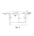
- Fig. 3 is a circuit diagram of a DC power converter according to an embodiment of the present invention.
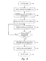
- Fig. 4 is a flowchart illustrating functions performed by a PMAD controller to provide pre-charge according to an embodiment of the present invention.
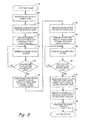
- Fig. 5 is a flowchart illustrating functions preferred by a PMAD controller to provide pre-charge according to another embodiment of the present invention.
- Fig. 6 is a flowchart illustrating functions performed by a PMAD controller to provide overload protection according to an embodiment of the present invention.
- Fig. 7 is a flowchart illustrating functions performed by a PMAD controller to provide current limiting according to an embodiment of the present invention.
- Fig. 1 is a block diagram of direct current (DC) power management and distribution (PMAD) system 10 according to an embodiment of the present invention.
- Power distribution system 10 includes power converter 12, hybrid solid-state circuit breakers (SSCB) 14a, 14b, 14c, and 14d, loads 16a, 16b, 16c, and 16d, and PMAD controller 17.
- Hybrid SSCB 14a, 14b, 14c, and 14d are selectively connected to distribute power to loads 16a, 16b, 16c, and 16d, respectively.
- Each hybrid SSCB 14a, 14b, 14c, and 14d is connected to receive power from main DC bus 18 and auxiliary DC bus 20.
- auxiliary DC bus 20 is provided by power converter 12, which receives power from main DC bus 18.
- PMAD controller 17 generates control signals to control the operation of power converter 12, and each of the plurality of hybrid SSCBs 14a, 14b, 14c, and 14d.
- Control signal 22 is provided to power converter 12 to enable and regulate the DC power supplied to auxiliary DC bus 20.
- Control signals 24a, 24a' are provided to hybrid SSCB 14a to control the supply of power from main DC bus 18 and auxiliary DC bus 20 to load 16a.
- control signal 24a is a main gate control signal that controls the distribution of power from main DC bus 18 to load 16a
- control signal 24a' is an auxiliary gate control signal that controls the distribution of power from auxiliary DC bus 20.
- control signals 24b, 24b', 24c, 24c', and 24d, 24d' are provided to hybrid SSCBs 14b, 14c, and 14d, respectively, to selectively control the supply of power from main DC bus 18 and auxiliary DC bus 20 to loads 16b, 16c, and 16d, respectively.
- Fig. 2 is a circuit diagram of DC hybrid solid-state circuit breaker (SSCB) 14a according to an embodiment of the present invention.
- Hybrid SSCB 14a includes main switch device 26, auxiliary switch device 28, and diode 30.
- main switch 26 is a power metal-oxide semiconductor field-effect transistor (MOSFET) device, although in other embodiments other well-known solid-state switch devices (SSSDs) may be employed.
- Main switch 26 is connected between main DC bus 18 and load 16a and is selectively turned On and Off via main gate signal 24a supplied by PMAD controller 17. When main switch 26 is On (i.e., "conductive"), then power from main DC bus 18 is supplied via main switch 26 to load 16a.
- MOSFET power metal-oxide semiconductor field-effect transistor
- SSSDs solid-state switch devices
- main switch 26 When main switch 26 is Off (i.e., "non-conductive"), then power from main DC bus 18 is prevented from being supplied via switch 26 to load 16a.
- a single main switch device 26 is illustrated, although in other embodiments a plurality of switching devices may be connected in parallel to satisfy desired power loss requirements.
- auxiliary switch device 28 is a thyristor (SCR), although in other embodiments other well-known SSSDs may be employed.
- Diode 30 is connected between the positive output provided to a load and a return line.
- auxiliary switch device 28 is a thyristor, selected for its high current rating as composed with MOSFET devices.
- Auxiliary switch 28 is connected between auxiliary DC bus 20 and load 16a and is selectively turned On and Off via auxiliary gate control signal 24a'. When auxiliary switch 28 is On (i.e., "conductive"), power from auxiliary DC bus 20 is supplied to load 16a. When auxiliary switch 28 is Off (i.e., "non-conductive"), then power from auxiliary DC bus 20 is prevented from being supplied via auxiliary switch 28 to load 16a.
- main DC bus 18 In general, during normal operation the gates of main switch 26 and auxiliary switch 28 are On. However, the voltage provided by main DC bus 18 is typically higher than the voltage supplied by auxiliary DC bus 20, and therefore the auxiliary SCR device is reversed bias, and power supplied to load 16a is provided by main DC bus 18 via main switch 26.
- Auxiliary DC bus 20 is utilized to implement various modes of operation that require regulation of the input power supplied to one or more loads. For example, PMAD controller 17 regulates auxiliary DC bus 20 during a pre-charge mode, overload protection mode, or current limiting mode. PMAD controller 17 regulates the power supplied to auxiliary DC bus 20 via power converter 12 (shown in Fig. 1 ).
- Fig. 3 is a circuit diagram of DC power converter 12 according to an embodiment of the present invention, which includes regulator switch 32, capacitor 34, diode 36, inductor 38, and capacitor 39.
- DC power converter 12 and associated components are arranged in a non-isolated step-down (buck) converter topology.
- buck step-down
- other DC-DC power converter topologies may be employed to provide a regulated DC output on auxiliary DC bus 20 from main DC bus 18.
- Regulator switch 32 is connected between main DC bus 18 and auxiliary DC bus 20.
- PMAD controller 17 controls the state of regulator switch 32 via control signal 22.
- regulator switch 32 When regulator switch 32 is turned On, voltage supplied by main DC bus 18 is provided directly to auxiliary DC bus 20, such that auxiliary DC bus 20 is unregulated.
- the duty ratio of regulator switch 32 By varying the duty ratio of regulator switch 32, the voltage supplied by main DC bus 18 is stepped down to a lower voltage for supply to auxiliary DC bus 20.
- PMAD system 10 (as shown in Fig. 1 ) utilizes power converter 12 and the plurality of hybrid SSCBs 14a-14d to implement various modes of operation, normal, pre-charge, overload protection, and current limiting. Each mode of operation is discussed in brief, with Figs. 4-7 providing additional details on functions performed during each mode of operation.
- PMAD system 10 operates to provide power to loads 16a-16d via the main switch (e.g., main switch 26 shown in Fig. 2 ). However, for operations that require regulation of the bus power provided to hybrid SSCBs 14a-14d, then PMAD controller 17 turns off the main switch and turns on the auxiliary switch (e.g., auxiliary switch 28 shown in Fig. 2 ). PMAD controller 17 then regulates auxiliary DC bus 20 via regulator switch 32 in power converter 12.
- Fig. 4 is a flowchart illustrating functions performed by PMAD controller 17 during a pre-charge operation according to an embodiment of the present invention.
- the pre-charge mode is used with respect to capacitive loads that may otherwise cause large in-rush currents at start-up.
- Pre-charge is implemented by utilizing power supplied by auxiliary DC bus 20 to charge the one or more capacitive loads, wherein PMAD controller 17 regulates the voltage on auxiliary DC bus 20 to prevent large in-rush currents.
- the functions are described with respect to pre-charge of capacitive load 16a.
- PMAD controller 17 initiates a pre-charge operation. This may be in response to a system start-up signal, or other input. Typically, a pre-charge operation is initiated prior to a normal operating mode.
- PMAD controller 17 turns Off main switch 26 (shown in Fig. 2 ) of hybrid SSCB 14a via control signal 24a.
- Auxiliary switch 28 is Off, and thus no power is supplied to load 16a.
- PMAD controller 17 regulates the voltage on auxiliary DC bus 20 to an initial level.
- PMAD controller 17 modulates control signal 22 to control the duty cycle of regulator switch 32 (shown in Fig. 3 ) to regulate the output voltage of power converter 12.
- PMAD controller 17 turns on auxiliary switch 28 via control signal 24a'.
- power is supplied to load 16a from auxiliary DC bus 20.
- the voltage (and therefore in-rush current) supplied to load 16a remains limited and allows pre-charging of capacitor load 16a.
- PMAD controller 17 increases the voltage on auxiliary DC bus 20 by regulating the voltage supplied by power converter 12. As discussed with respect to Fig. 3 , PMAD controller 17 increases the voltage supplied by power converter 12 by increasing the duty cycle of regulator switch 32. In one embodiment, PMAD controller 17 increases the voltage provided by power converter 12 at a pre-determined rate to gradually increase the voltage supplied to the load without creating large in-rush currents.
- PMAD controller 17 determines whether the voltage on auxiliary DC bus 20 has reached a threshold or rated level. If the voltage on auxiliary DC bus 20 has not reached the threshold level, then the process continues at step 48, with PMAD controller 17 continually increasing the voltage on auxiliary DC bus 20. If the voltage on auxiliary DC bus 20 has reached the threshold level, then at step 52 PMAD controller 17 turns on main switch 26 and turns off the gate of auxiliary switch 28. As a result, power from main DC bus 18 is supplied to load 14a. At step 54, PMAD controller 54 provides a signal or otherwise announces that pre-charge is complete. At step 56, operation in the pre-charge mode is exited.
- Fig. 5 is a flowchart illustrating functions performed by PMAD controller 17 during a pre-charge operation of two or more loads according to an embodiment of the present invention.
- PMAD controller 17 In contrast with the embodiment described with respect to Fig. 4 , in the embodiment shown in Fig. 5 two or more capacitive loads are charged via a pre-charge process. To illustrate, the functions are described with respect to pre-charge of respective loads 16a and 16b.
- PMAD controller 17 initiates a pre-charge operation. This may be in response to a system start-up signal, or other input.
- PMAD controller 17 turns Off the main switch of hybrid SSCBs 14a-14d. For example, if loads 16a and 16b are capacitive loads to be pre-charged, then PMAD controller 17 turns Off the main switches associated with each hybrid SSCB via control signals 24a and 24b. Auxiliary switches associated with hybrid SSCBs 14a and 14b are Off, and thus no power is supplied to the load.
- PMAD controller 17 regulates the output voltage of power converter 12 to a desired level for provision to auxiliary DC bus 20.
- PMAD controller 17 regulates the duty cycle of regulator switch 32 (shown in Fig. 3 ) to regulate the output voltage of power converter 12.
- PMAD controller 17 turns on auxiliary switch 28 employed in a first hybrid SSCB associated with a first capacitive load. For example, if load 16a is to be pre-charged first, then PMAD controller 17 turns on auxiliary switch 28 located in hybrid SSCB 14a via control signal 24a', while maintaining other auxiliary SSCBs located in hybrid SSCBs 14b-14d Off. As a result, power is supplied to load 16a from auxiliary DC bus 20 at a voltage determined by the regulated output of by power converter 12, while no power is supplied to loads 16b-16d. By maintaining the voltage provided by power converter 12 at a relatively low voltage (as described at step 66), the voltage (and therefore in-rush current) supplied to load 16a remains limited.
- PMAD controller 17 increases the voltage on auxiliary DC bus 20 by regulating the voltage supplied by power converter 12. As discussed with respect to Fig. 3 , PMAD controller 17 increases the voltage supplied by power converter 12 by increasing the duty cycle of regulator switch 32, controlled via control signal 22. In one embodiment, PMAD controller 17 increases the voltage provided by power converter 12 at a pre-determined rate. As a result, the voltage and current supplied to the load (e.g., load 16a) is increased gradually, thereby eliminating in-rush currents.
- PMAD controller 17 determines whether the voltage on auxiliary DC bus 20 has reached a threshold or rated level. If the voltage on auxiliary DC bus 20 has not reached the threshold level, then the process continues at step 70 with PMAD controller 17 increasing the voltage on auxiliary DC bus 20. If the voltage on auxiliary DC bus 20 has reached the threshold level, then at step 74 PMAD controller 17 turns On main switch 26 and turns Off the gate of auxiliary switch 28 of the hybrid SSCB (e.g., hybrid SSCB 14a) associated with the first capacitive load (e.g., load 16a). As a result, power is supplied to the first capacitive load from main DC bus 18.
- the hybrid SSCB e.g., hybrid SSCB 14a
- PMAD controller 17 begins the process for turning On the next or second capacitive load (e.g., load 16b).
- PMAD controller 17 reduces the voltage on auxiliary DC bus 18 to the initial level discussed with respect to step 66.
- PMAD controller 17 regulates the voltage on auxiliary DC bus 18 via power converter 12.
- PMAD controller 17 turns On the auxiliary switch (not shown) of hybrid SSCB 14b via control signal 24b'. In this way, the second capacitive load begins receiving power from auxiliary DC bus 20, but in-rush currents are prevented because the voltage on auxiliary DC bus 20 is regulated to a relatively low level.
- PMAD controller 17 increases the voltage on auxiliary DC bus 20.
- PMAD controller 17 increases the voltage at a pre-determined rate by regulating the output of power converter 12.
- PMAD controller 17 determines whether the voltage on auxiliary DC bus 20 has reached a threshold or rated level. If the voltage on auxiliary DC bus 20 has not reached the threshold level, then the process continues at step 80 with PMAD controller 17 increasing the voltage on auxiliary DC bus 20. If the voltage on auxiliary DC bus 20 has reached the threshold level, then at step 84 PMAD controller 17 turns On the main switch and turns Off the auxiliary switch (not shown) of hybrid SSCB 14b associated with second capacitive load 16b. As a result, power is supplied to the second capacitive load 16b from main DC bus 18.
- PMAD controller 17 turns On the auxiliary switch 28 associated with the first hybrid SSCB 14a and maintains in the On state the auxiliary switch associated with second hybrid SSCB 14b. In this way, the auxiliary switches associated with each hybrid SSCB, as well as the main switches, are turned On as PMAD controller 17 transitions from pre-charge mode to normal mode.
- PMAD controller 17 announces that pre-charge is complete, and at step 90 exits the pre-charge mode. In this way, PMAD controller provides sequential pre-charge of each capacitive load, thereby avoiding in-rush currents for each capacitive load.
- Fig. 6 is a flowchart illustrating functions performed by PMAD controller 17 to initiate and provide overload protection according to an embodiment of the present invention. To illustrate, the functions are described with respect to an overload condition detected with respect to hybrid SSCB 14a and respective load 16a.
- PMAD controller 17 routes power through the auxiliary switch of the hybrid SSCB, wherein the auxiliary switch is capable of handling higher currents. If the overload condition persists, then the auxiliary switch is turned Off and auxiliary DC bus 20 is de-energized (i.e., voltage is reduced).
- Overload protection is initiated at step 96. This does not mean that PMAD controller 17 enters an overload protection mode, only that PMAD controller 17 is beginning the process of monitoring for overload conditions. In one embodiment, overload protection may be initiated when PMAD controller 17 exits the pre-charge mode and begins normal operating mode.
- PMAD controller 17 turns On main switch 26 of hybrid SSCB 14a. If main switch 26 is already On, then PMAD controller 17 maintains main switch 26 in an On state. In addition, PMAD controller 17 turns on regulator switch 32 associated with power converter 12 to provide an unregulated DC output to auxiliary DC bus 20. This represents the "normal" operating mode for PMAD system 10.
- PMAD controller 17 determines whether the load current exceeds a rated level. In one embodiment, PMAD controller 17 compares the monitored load current to a trip threshold. In another embodiment PMAD controller 17 utilizes a trip curve to determine the presence of an overload condition. If the monitored current does not exceed a rated level, then monitoring continues at step 100. If the monitored current does exceed a rated level, then PMAD controller 17 initiates overload protection mode at step 102.
- PMAD controller 17 turns off main switch 26 within hybrid SSCB 14a to prevent power from main DC bus 18 being supplied to load 16a.
- Auxiliary switch 28 remains On, and power is supplied to load 16a from auxiliary DC bus 20.
- auxiliary DC bus 20 is unregulated at this point, and therefore provides a voltage very similar to the voltage supplied by main DC bus 18.
- PMAD controller 17 determines whether the load current exceeds a second rated (I ⁇ 2t trip curve) threshold value. If at step 104, PMAD controller 17 determines that the second rated threshold (or trip curve) has not been exceeded, then at step 106 PMAD controller 17 determines whether the monitored load current still exceeds the first rated threshold value utilized at step 100. If the monitored current does exceed the first rated threshold value, then PMAD controller 17 continue monitoring the current and comparing it to the second rated threshold value at step 104. If the monitored current no longer exceeds the first rated threshold value, then at step 108 PMAD controller 17 turns On main switch 26 to supply power to load 16a from main DC bus 18.
- PMAD controller 17 may turn Off auxiliary switch 28, although in other embodiments auxiliary switch 28 may remain On, with a majority of the current being supplied from main DC bus 18 via main switch 26.
- the overload protection mode is exited and the normal operating mode continues.
- PMAD controller 17 determines that the monitored current exceeds the second rated (I ⁇ 2t) threshold, then at step 112 PMAD controller 17 turns Off the gate of auxiliary switch 28.
- auxiliary switch 28 can only be turn off by reducing anode to cathode voltage so the current falls below the minimum holding current level.
- PMAD controller 17 reduces the voltage on auxiliary DC bus 20 to a minimum level (via power converter 12).
- PMAD controller 17 determines whether the load current falls below a third rated threshold level.
- the third rated threshold level employed at step 114 is less than the holding current level of the thyristor (i.e., SCR). If the current has not decreased below the third rated threshold level, then the process continues at step 112 with PMAD controller 17 maintaining the gate of auxiliary switch 28 in the Off position and reducing the auxiliary DC bus voltage 20 to a minimum level.
- step 114 If at step 114 the monitored load current does fall below the third rated threshold level, this indicates that the power has been successfully disconnected from the faulty load.
- PMAD controller 17 turns on power converter 12 to supply power to auxiliary DC bus 20.
- step 118 PMAD controller 17 announces the presence of an overload fault with respect to the faulty load, and exits the overload protection mode at step 110.
- Fig. 7 is a flowchart illustrating functions performed by PMAD controller 17 to provide current limiting according to an embodiment of the present invention. To illustrate, the functions are described with respect to an overload condition detected with respect to hybrid SSCB 14a and respective load 16a. In general, current limiting is provided in response to an overcurrent condition, in which PMAD controller 17 turns Off the main switch and limits the current by limiting the voltage made available on auxiliary DC bus 20.
- PMAD controller 17 turns On main switch 26.
- PMAD controller 17 turns On regulator switch 32 associated with power converter 12, if not already On, to supply power to auxiliary DC bus 20.
- PMAD controller 17 determines whether the load current exceeds a first rated threshold, which may be the same or different than the rated threshold level employed in the overload protection mode of operation. If the monitored load current does not exceed the first rated threshold, then PMAD controller 17 continues monitoring the load current at step 126. If the monitored load current does exceed the rated threshold level, then at step 128 PMAD controller 17 turns Off main switch 26 and turns On (if not already On) auxiliary switch 28. In this way, power is supplied to load 16a from auxiliary DC bus 20.
- a first rated threshold which may be the same or different than the rated threshold level employed in the overload protection mode of operation. If the monitored load current does not exceed the first rated threshold, then PMAD controller 17 continues monitoring the load current at step 126. If the monitored load current does exceed the rated threshold level, then at step 128 PMAD controller 17 turns Off main switch 26 and turns On (if not already On) auxiliary switch 28. In this way, power is supplied to load 16a from auxiliary DC bus 20.
- PMAD controller 17 regulates the voltage on auxiliary DC bus 20 via power converter 12 to maintain a desired current through auxiliary switch 28.
- PMAD controller 17 selectively increases or decreases the voltage supplied by power converter 12 to regulate the current monitored through auxiliary switch 28.
- PMAD controller 17 determines whether the period of operation of the current limiting mode has exceeded a predetermined time limit. If the predetermined time limit has not been exceeded, then PMAD controller 17 determines at step 134 whether the load current exceeds a second rated threshold. In one embodiment, the second rated threshold is the same as the first rated threshold employed at step 126, although in other embodiments different thresholds could be employed. If the second rated threshold is still exceeded, then the process continues at step 130 with PMAD controller 17 regulating the current through auxiliary switch 28 via current regulator 12.
- PMAD controller 17 determines that the load fault has cleared and normal operation can resume.
- PMAD controller 17 increases the voltage supplied by power converter 12 to auxiliary DC bus 20. In one embodiment, controller 17 turns On regulator switch 32 to provide an unregulated DC output to auxiliary DC bus 20. At step 140, PMAD controller exits the current limiting mode.
- PMAD controller 17 turns Off auxiliary switch 28.
- PMAD controller 17 reduces the voltage supplied by power converter 12 to auxiliary DC bus 20 to allow the current through auxiliary switch 28 to fall below the holding current (if implemented with an thyristor), resulting in auxiliary switch 28 turning off and disconnecting power to the faulty load 16a.
- PMAD controller 17 determines whether the monitored load current has fallen below a third threshold level below the holding current level of auxiliary switch 28, when implemented as a thyristor). If the monitored load current has not decreased below the third threshold, then at step 142 PMAD controller 17 continues maintaining auxiliary switch 28 in the Off state and reducing the voltage made available on auxiliary DC bus 20 to allow current through auxiliary switch 28 to fall below the holding current level, resulting in auxiliary switch 28 (when implemented as an SCR) turning Off and disconnecting power to the faulty load 16a.
- step 146 If the monitored current is less than the third rated threshold, then an overcurrent condition is announced at step 146.
- Main switch 26 and auxiliary switch 28 remain Off to isolate faulty load 16a, but at step 138 PMAD controller 17 controls power converter 12 to supply power once again to auxiliary DC bus 20.
- step 140 the current limiting mode is exited.
Landscapes
- Engineering & Computer Science (AREA)
- Power Engineering (AREA)
- Direct Current Feeding And Distribution (AREA)
Description
- The present invention is related to power management and distribution (PMAD) systems and in particular to PMAD systems employing hybrid solid-state circuit breaker (SSCB) circuits.
- Power management and distribution (PMAD) systems control the supply of DC and/or AC power to various loads. Circuit breakers and switches are commonly employed by these systems to not only control the supply of power to the various loads but also to protect the load from fault conditions. More recently, solid-state circuit breakers (SSCBs) have been employed to provide fast response time, eliminate arcing during turn-off, and prevent bouncing during turn-on transients. For example, power semiconductor devices such as metal-oxide semiconductor field effect transistors (MOSFETs) or insulated gate bipolar transistors (IGBT) are commonly employed by SSCBs to control the distribution of power to a load. In particular, power MOSFETs are commonly employed due to their low conduction losses when conducting. The SSCB is part of a solid-state power controller (SSPC) that includes a controller, current and voltage sensors to monitor the current and voltage, respectively, provided to the load by a power semiconductor device and emulates traditional circuit breaker functionality by turning the power semiconductor device Off to protect the associated load from fault conditions. Thermal sensors may also be employed to protect the SSCB.
- One of the specifics of SSCB is high overload requirements that may exceed 1000% of the rated current. To achieve this high current rating, a large number of MOSFET devices are connected in parallel. MOSFETS can be easily paralleled, because of the positive thermal coefficient of their on-state resistance. However, during overload transient conditions the MOSFETs within SSCB may be subject to a current imbalance that results in a particular device exceeding its peak current or continuous thermal ratings. This condition creates reliability concerns. Unbalance may be caused by parameter mismatches between semiconductor devices, gate drive parameter mismatches, and/or power circuit parameter mismatches. There is a need to improve SSCB and PMAD architecture to meet high overload transient requirements without over sizing the SSCB.
- A power management and distribution (PMAD) system includes a main DC bus, an auxiliary DC bus, a power converter, one or more hybrid solid-state circuit breakers, and a controller. The power converter converts power from the main DC bus to provide a regulated output to the auxiliary bus. Each hybrid SSCB includes a main switch connected between the main DC bus and a load and an auxiliary switch connected between the auxiliary DC bus and the load. The controller selectively turns the main switch and the auxiliary switch On/Off to selectively supply power from the main DC bus and/or the auxiliary DC bus to the load, and to selectively regulate the voltage on the auxiliary DC bus.
-
Fig. 1 is a block diagram of a direct current (DC) power management distribution (PMAD) system according to an embodiment of the present invention. -
Fig. 2 is a circuit diagram of a DC hybrid solid-state circuit breaker (SSCB) according to an embodiment of the present invention. -
Fig. 3 is a circuit diagram of a DC power converter according to an embodiment of the present invention. -
Fig. 4 is a flowchart illustrating functions performed by a PMAD controller to provide pre-charge according to an embodiment of the present invention. -
Fig. 5 is a flowchart illustrating functions preferred by a PMAD controller to provide pre-charge according to another embodiment of the present invention. -
Fig. 6 is a flowchart illustrating functions performed by a PMAD controller to provide overload protection according to an embodiment of the present invention. -
Fig. 7 is a flowchart illustrating functions performed by a PMAD controller to provide current limiting according to an embodiment of the present invention. -
Fig. 1 is a block diagram of direct current (DC) power management and distribution (PMAD)system 10 according to an embodiment of the present invention.Power distribution system 10 includespower converter 12, hybrid solid-state circuit breakers (SSCB) 14a, 14b, 14c, and 14d, loads 16a, 16b, 16c, and 16d, and PMAD controller 17.Hybrid SSCB hybrid SSCB main DC bus 18 andauxiliary DC bus 20. In the embodiment shown inFig. 1 ,auxiliary DC bus 20 is provided bypower converter 12, which receives power frommain DC bus 18. - PMAD controller 17 generates control signals to control the operation of
power converter 12, and each of the plurality ofhybrid SSCBs Control signal 22 is provided topower converter 12 to enable and regulate the DC power supplied toauxiliary DC bus 20.Control signals main DC bus 18 andauxiliary DC bus 20 to load 16a. In particular,control signal 24a is a main gate control signal that controls the distribution of power frommain DC bus 18 to load 16a andcontrol signal 24a' is an auxiliary gate control signal that controls the distribution of power fromauxiliary DC bus 20. Likewise, control signals 24b, 24b', 24c, 24c', and 24d, 24d' are provided tohybrid SSCBs main DC bus 18 andauxiliary DC bus 20 to loads 16b, 16c, and 16d, respectively. -
Fig. 2 is a circuit diagram of DC hybrid solid-state circuit breaker (SSCB) 14a according to an embodiment of the present invention. Hybrid SSCB 14a includesmain switch device 26,auxiliary switch device 28, anddiode 30. In the embodiment shown inFig. 2 ,main switch 26 is a power metal-oxide semiconductor field-effect transistor (MOSFET) device, although in other embodiments other well-known solid-state switch devices (SSSDs) may be employed.Main switch 26 is connected betweenmain DC bus 18 and load 16a and is selectively turned On and Off viamain gate signal 24a supplied by PMAD controller 17. Whenmain switch 26 is On (i.e., "conductive"), then power frommain DC bus 18 is supplied viamain switch 26 to load 16a. Whenmain switch 26 is Off (i.e., "non-conductive"), then power frommain DC bus 18 is prevented from being supplied viaswitch 26 to load 16a. In the embodiment shown inFig. 2 , a singlemain switch device 26 is illustrated, although in other embodiments a plurality of switching devices may be connected in parallel to satisfy desired power loss requirements. - In the embodiment shown in
Fig. 2 ,auxiliary switch device 28 is a thyristor (SCR), although in other embodiments other well-known SSSDs may be employed.Diode 30 is connected between the positive output provided to a load and a return line. In the embodiment shown inFig. 2 auxiliary switch device 28 is a thyristor, selected for its high current rating as composed with MOSFET devices.Auxiliary switch 28 is connected betweenauxiliary DC bus 20 and load 16a and is selectively turned On and Off via auxiliarygate control signal 24a'. Whenauxiliary switch 28 is On (i.e., "conductive"), power fromauxiliary DC bus 20 is supplied to load 16a. Whenauxiliary switch 28 is Off (i.e., "non-conductive"), then power fromauxiliary DC bus 20 is prevented from being supplied viaauxiliary switch 28 to load 16a. - In general, during normal operation the gates of
main switch 26 andauxiliary switch 28 are On. However, the voltage provided bymain DC bus 18 is typically higher than the voltage supplied byauxiliary DC bus 20, and therefore the auxiliary SCR device is reversed bias, and power supplied to load 16a is provided bymain DC bus 18 viamain switch 26.Auxiliary DC bus 20 is utilized to implement various modes of operation that require regulation of the input power supplied to one or more loads. For example, PMAD controller 17 regulatesauxiliary DC bus 20 during a pre-charge mode, overload protection mode, or current limiting mode. PMAD controller 17 regulates the power supplied toauxiliary DC bus 20 via power converter 12 (shown inFig. 1 ). -
Fig. 3 is a circuit diagram ofDC power converter 12 according to an embodiment of the present invention, which includesregulator switch 32,capacitor 34,diode 36,inductor 38, andcapacitor 39. In the embodiment shown inFig. 3 ,DC power converter 12 and associated components are arranged in a non-isolated step-down (buck) converter topology. In other embodiments, other DC-DC power converter topologies may be employed to provide a regulated DC output onauxiliary DC bus 20 frommain DC bus 18. -
Regulator switch 32 is connected betweenmain DC bus 18 andauxiliary DC bus 20. PMAD controller 17 controls the state ofregulator switch 32 viacontrol signal 22. Whenregulator switch 32 is turned On, voltage supplied bymain DC bus 18 is provided directly toauxiliary DC bus 20, such thatauxiliary DC bus 20 is unregulated. By varying the duty ratio ofregulator switch 32, the voltage supplied bymain DC bus 18 is stepped down to a lower voltage for supply toauxiliary DC bus 20. PMAD system 10 (as shown inFig. 1 ) utilizespower converter 12 and the plurality ofhybrid SSCBs 14a-14d to implement various modes of operation, normal, pre-charge, overload protection, and current limiting. Each mode of operation is discussed in brief, withFigs. 4-7 providing additional details on functions performed during each mode of operation. In general,PMAD system 10 operates to provide power to loads 16a-16d via the main switch (e.g.,main switch 26 shown inFig. 2 ). However, for operations that require regulation of the bus power provided tohybrid SSCBs 14a-14d, then PMAD controller 17 turns off the main switch and turns on the auxiliary switch (e.g.,auxiliary switch 28 shown inFig. 2 ). PMAD controller 17 then regulatesauxiliary DC bus 20 viaregulator switch 32 inpower converter 12. -
Fig. 4 is a flowchart illustrating functions performed by PMAD controller 17 during a pre-charge operation according to an embodiment of the present invention. The pre-charge mode is used with respect to capacitive loads that may otherwise cause large in-rush currents at start-up. Pre-charge is implemented by utilizing power supplied byauxiliary DC bus 20 to charge the one or more capacitive loads, wherein PMAD controller 17 regulates the voltage onauxiliary DC bus 20 to prevent large in-rush currents. To illustrate, the functions are described with respect to pre-charge of capacitive load 16a. - At
step 40, PMAD controller 17 initiates a pre-charge operation. This may be in response to a system start-up signal, or other input. Typically, a pre-charge operation is initiated prior to a normal operating mode. - At
step 42, PMAD controller 17 turns Off main switch 26 (shown inFig. 2 ) ofhybrid SSCB 14a viacontrol signal 24a.Auxiliary switch 28 is Off, and thus no power is supplied to load 16a. - At
step 44, PMAD controller 17 regulates the voltage onauxiliary DC bus 20 to an initial level. In the embodiment shown inFig. 3 , PMAD controller 17 modulates controlsignal 22 to control the duty cycle of regulator switch 32 (shown inFig. 3 ) to regulate the output voltage ofpower converter 12. - At
step 46, PMAD controller 17 turns onauxiliary switch 28 viacontrol signal 24a'. As a result, power is supplied to load 16a fromauxiliary DC bus 20. By maintaining the voltage provided bypower converter 12 toauxiliary DC bus 20 at a relatively low voltage (as described at step 44), the voltage (and therefore in-rush current) supplied to load 16a remains limited and allows pre-charging of capacitor load 16a. - At
step 48, PMAD controller 17 increases the voltage onauxiliary DC bus 20 by regulating the voltage supplied bypower converter 12. As discussed with respect toFig. 3 , PMAD controller 17 increases the voltage supplied bypower converter 12 by increasing the duty cycle ofregulator switch 32. In one embodiment, PMAD controller 17 increases the voltage provided bypower converter 12 at a pre-determined rate to gradually increase the voltage supplied to the load without creating large in-rush currents. - At
step 50, PMAD controller 17 determines whether the voltage onauxiliary DC bus 20 has reached a threshold or rated level. If the voltage onauxiliary DC bus 20 has not reached the threshold level, then the process continues atstep 48, with PMAD controller 17 continually increasing the voltage onauxiliary DC bus 20. If the voltage onauxiliary DC bus 20 has reached the threshold level, then atstep 52 PMAD controller 17 turns onmain switch 26 and turns off the gate ofauxiliary switch 28. As a result, power frommain DC bus 18 is supplied to load 14a. Atstep 54,PMAD controller 54 provides a signal or otherwise announces that pre-charge is complete. Atstep 56, operation in the pre-charge mode is exited. -
Fig. 5 is a flowchart illustrating functions performed by PMAD controller 17 during a pre-charge operation of two or more loads according to an embodiment of the present invention. In contrast with the embodiment described with respect toFig. 4 , in the embodiment shown inFig. 5 two or more capacitive loads are charged via a pre-charge process. To illustrate, the functions are described with respect to pre-charge ofrespective loads 16a and 16b. - At
step 62, PMAD controller 17 initiates a pre-charge operation. This may be in response to a system start-up signal, or other input. Atstep 64, PMAD controller 17 turns Off the main switch ofhybrid SSCBs 14a-14d. For example, ifloads 16a and 16b are capacitive loads to be pre-charged, then PMAD controller 17 turns Off the main switches associated with each hybrid SSCB viacontrol signals 24a and 24b. Auxiliary switches associated withhybrid SSCBs - At
step 66, PMAD controller 17 regulates the output voltage ofpower converter 12 to a desired level for provision toauxiliary DC bus 20. In one embodiment, PMAD controller 17 regulates the duty cycle of regulator switch 32 (shown inFig. 3 ) to regulate the output voltage ofpower converter 12. - At
step 68, PMAD controller 17 turns onauxiliary switch 28 employed in a first hybrid SSCB associated with a first capacitive load. For example, if load 16a is to be pre-charged first, then PMAD controller 17 turns onauxiliary switch 28 located inhybrid SSCB 14a viacontrol signal 24a', while maintaining other auxiliary SSCBs located inhybrid SSCBs 14b-14d Off. As a result, power is supplied to load 16a fromauxiliary DC bus 20 at a voltage determined by the regulated output of bypower converter 12, while no power is supplied toloads 16b-16d. By maintaining the voltage provided bypower converter 12 at a relatively low voltage (as described at step 66), the voltage (and therefore in-rush current) supplied to load 16a remains limited. - At
step 72, PMAD controller 17 increases the voltage onauxiliary DC bus 20 by regulating the voltage supplied bypower converter 12. As discussed with respect toFig. 3 , PMAD controller 17 increases the voltage supplied bypower converter 12 by increasing the duty cycle ofregulator switch 32, controlled viacontrol signal 22. In one embodiment, PMAD controller 17 increases the voltage provided bypower converter 12 at a pre-determined rate. As a result, the voltage and current supplied to the load (e.g., load 16a) is increased gradually, thereby eliminating in-rush currents. - At
step 74, PMAD controller 17 determines whether the voltage onauxiliary DC bus 20 has reached a threshold or rated level. If the voltage onauxiliary DC bus 20 has not reached the threshold level, then the process continues atstep 70 with PMAD controller 17 increasing the voltage onauxiliary DC bus 20. If the voltage onauxiliary DC bus 20 has reached the threshold level, then atstep 74 PMAD controller 17 turns Onmain switch 26 and turns Off the gate ofauxiliary switch 28 of the hybrid SSCB (e.g.,hybrid SSCB 14a) associated with the first capacitive load (e.g., load 16a). As a result, power is supplied to the first capacitive load frommain DC bus 18. - At
step 76, with the first capacitive load fully On and receiving power frommain DC bus 18, PMAD controller begins the process for turning On the next or second capacitive load (e.g.,load 16b). Atstep 76, PMAD controller 17 reduces the voltage onauxiliary DC bus 18 to the initial level discussed with respect to step 66. Once again, PMAD controller 17 regulates the voltage onauxiliary DC bus 18 viapower converter 12. - At
step 78, PMAD controller 17 turns On the auxiliary switch (not shown) ofhybrid SSCB 14b via control signal 24b'. In this way, the second capacitive load begins receiving power fromauxiliary DC bus 20, but in-rush currents are prevented because the voltage onauxiliary DC bus 20 is regulated to a relatively low level. - At step 80, PMAD controller 17 increases the voltage on
auxiliary DC bus 20. In one embodiment, PMAD controller 17 increases the voltage at a pre-determined rate by regulating the output ofpower converter 12. - At
step 82, PMAD controller 17 determines whether the voltage onauxiliary DC bus 20 has reached a threshold or rated level. If the voltage onauxiliary DC bus 20 has not reached the threshold level, then the process continues at step 80 with PMAD controller 17 increasing the voltage onauxiliary DC bus 20. If the voltage onauxiliary DC bus 20 has reached the threshold level, then atstep 84 PMAD controller 17 turns On the main switch and turns Off the auxiliary switch (not shown) ofhybrid SSCB 14b associated withsecond capacitive load 16b. As a result, power is supplied to thesecond capacitive load 16b frommain DC bus 18. - At
step 86, PMAD controller 17 turns On theauxiliary switch 28 associated with thefirst hybrid SSCB 14a and maintains in the On state the auxiliary switch associated with secondhybrid SSCB 14b. In this way, the auxiliary switches associated with each hybrid SSCB, as well as the main switches, are turned On as PMAD controller 17 transitions from pre-charge mode to normal mode. - At
step 88, PMAD controller 17 announces that pre-charge is complete, and atstep 90 exits the pre-charge mode. In this way, PMAD controller provides sequential pre-charge of each capacitive load, thereby avoiding in-rush currents for each capacitive load. -
Fig. 6 is a flowchart illustrating functions performed by PMAD controller 17 to initiate and provide overload protection according to an embodiment of the present invention. To illustrate, the functions are described with respect to an overload condition detected with respect tohybrid SSCB 14a and respective load 16a. In general, with a detected overload condition, PMAD controller 17 routes power through the auxiliary switch of the hybrid SSCB, wherein the auxiliary switch is capable of handling higher currents. If the overload condition persists, then the auxiliary switch is turned Off andauxiliary DC bus 20 is de-energized (i.e., voltage is reduced). - Overload protection is initiated at step 96. This does not mean that PMAD controller 17 enters an overload protection mode, only that PMAD controller 17 is beginning the process of monitoring for overload conditions. In one embodiment, overload protection may be initiated when PMAD controller 17 exits the pre-charge mode and begins normal operating mode.
- At
step 98, PMAD controller 17 turns Onmain switch 26 ofhybrid SSCB 14a. Ifmain switch 26 is already On, then PMAD controller 17 maintainsmain switch 26 in an On state. In addition, PMAD controller 17 turns onregulator switch 32 associated withpower converter 12 to provide an unregulated DC output toauxiliary DC bus 20. This represents the "normal" operating mode forPMAD system 10. - At
step 100, PMAD controller 17 determines whether the load current exceeds a rated level. In one embodiment, PMAD controller 17 compares the monitored load current to a trip threshold. In another embodiment PMAD controller 17 utilizes a trip curve to determine the presence of an overload condition. If the monitored current does not exceed a rated level, then monitoring continues atstep 100. If the monitored current does exceed a rated level, then PMAD controller 17 initiates overload protection mode atstep 102. - At
step 102, in response to the monitored current exceeding the rated level, PMAD controller 17 turns offmain switch 26 withinhybrid SSCB 14a to prevent power frommain DC bus 18 being supplied to load 16a.Auxiliary switch 28 remains On, and power is supplied to load 16a fromauxiliary DC bus 20. In one embodiment,auxiliary DC bus 20 is unregulated at this point, and therefore provides a voltage very similar to the voltage supplied bymain DC bus 18. - At
step 104, PMAD controller 17 determines whether the load current exceeds a second rated (I^2t trip curve) threshold value. If atstep 104, PMAD controller 17 determines that the second rated threshold (or trip curve) has not been exceeded, then atstep 106 PMAD controller 17 determines whether the monitored load current still exceeds the first rated threshold value utilized atstep 100. If the monitored current does exceed the first rated threshold value, then PMAD controller 17 continue monitoring the current and comparing it to the second rated threshold value atstep 104. If the monitored current no longer exceeds the first rated threshold value, then atstep 108 PMAD controller 17 turns Onmain switch 26 to supply power to load 16a frommain DC bus 18. In addition, PMAD controller 17 may turn Offauxiliary switch 28, although in other embodimentsauxiliary switch 28 may remain On, with a majority of the current being supplied frommain DC bus 18 viamain switch 26. At step 110, with the monitored current now below both the first rated threshold and the second rated threshold, the overload protection mode is exited and the normal operating mode continues. - If at
step 104, PMAD controller 17 determines that the monitored current exceeds the second rated (I^2t) threshold, then atstep 112 PMAD controller 17 turns Off the gate ofauxiliary switch 28. To prevent power from being supplied to the load from eithermain DC bus 18 orauxiliary DC bus 20, both main and auxiliary switches must be turn-off. When implemented as a thyristor,auxiliary switch 28 can only be turn off by reducing anode to cathode voltage so the current falls below the minimum holding current level. Thus, PMAD controller 17 reduces the voltage onauxiliary DC bus 20 to a minimum level (via power converter 12). - At
step 114, PMAD controller 17 determines whether the load current falls below a third rated threshold level. The third rated threshold level employed atstep 114 is less than the holding current level of the thyristor (i.e., SCR). If the current has not decreased below the third rated threshold level, then the process continues atstep 112 with PMAD controller 17 maintaining the gate ofauxiliary switch 28 in the Off position and reducing the auxiliaryDC bus voltage 20 to a minimum level. - If at
step 114 the monitored load current does fall below the third rated threshold level, this indicates that the power has been successfully disconnected from the faulty load. Atstep 116, PMAD controller 17 turns onpower converter 12 to supply power toauxiliary DC bus 20. Atstep 118, PMAD controller 17 announces the presence of an overload fault with respect to the faulty load, and exits the overload protection mode at step 110. -
Fig. 7 is a flowchart illustrating functions performed by PMAD controller 17 to provide current limiting according to an embodiment of the present invention. To illustrate, the functions are described with respect to an overload condition detected with respect tohybrid SSCB 14a and respective load 16a. In general, current limiting is provided in response to an overcurrent condition, in which PMAD controller 17 turns Off the main switch and limits the current by limiting the voltage made available onauxiliary DC bus 20. - Current limiting mode of operation is enabled at
step 122, although current limiting will not be initiated unless a faulty load is detected. Once again, operation is discussed with respect tohybrid SSCB 14a and corresponding load 16a. Atstep 124, PMAD controller 17 turns Onmain switch 26. In addition, PMAD controller 17 turns Onregulator switch 32 associated withpower converter 12, if not already On, to supply power toauxiliary DC bus 20. - At
step 126, PMAD controller 17 determines whether the load current exceeds a first rated threshold, which may be the same or different than the rated threshold level employed in the overload protection mode of operation. If the monitored load current does not exceed the first rated threshold, then PMAD controller 17 continues monitoring the load current atstep 126. If the monitored load current does exceed the rated threshold level, then atstep 128 PMAD controller 17 turns Offmain switch 26 and turns On (if not already On)auxiliary switch 28. In this way, power is supplied to load 16a fromauxiliary DC bus 20. - At
step 130, PMAD controller 17 regulates the voltage onauxiliary DC bus 20 viapower converter 12 to maintain a desired current throughauxiliary switch 28. PMAD controller 17 selectively increases or decreases the voltage supplied bypower converter 12 to regulate the current monitored throughauxiliary switch 28. - At
step 132, PMAD controller 17 determines whether the period of operation of the current limiting mode has exceeded a predetermined time limit. If the predetermined time limit has not been exceeded, then PMAD controller 17 determines atstep 134 whether the load current exceeds a second rated threshold. In one embodiment, the second rated threshold is the same as the first rated threshold employed atstep 126, although in other embodiments different thresholds could be employed. If the second rated threshold is still exceeded, then the process continues atstep 130 with PMAD controller 17 regulating the current throughauxiliary switch 28 viacurrent regulator 12. - If the second rated threshold level has been exceeded, then at
step 136 PMAD controller 17 turns Onmain switch 26 and turns Off the gate ofauxiliary switch 28 to supply power to load 16a frommain DC bus 18. That is, PMAD controller 17 determines that the load fault has cleared and normal operation can resume. - At
step 138, PMAD controller 17 increases the voltage supplied bypower converter 12 toauxiliary DC bus 20. In one embodiment, controller 17 turns Onregulator switch 32 to provide an unregulated DC output toauxiliary DC bus 20. Atstep 140, PMAD controller exits the current limiting mode. - If at
step 132, the pre-determined time limit threshold is exceeded, then atstep 142 PMAD controller 17 turns Offauxiliary switch 28. In addition, PMAD controller 17 reduces the voltage supplied bypower converter 12 toauxiliary DC bus 20 to allow the current throughauxiliary switch 28 to fall below the holding current (if implemented with an thyristor), resulting inauxiliary switch 28 turning off and disconnecting power to the faulty load 16a. - At
step 144, PMAD controller 17 determines whether the monitored load current has fallen below a third threshold level below the holding current level ofauxiliary switch 28, when implemented as a thyristor). If the monitored load current has not decreased below the third threshold, then atstep 142 PMAD controller 17 continues maintainingauxiliary switch 28 in the Off state and reducing the voltage made available onauxiliary DC bus 20 to allow current throughauxiliary switch 28 to fall below the holding current level, resulting in auxiliary switch 28 (when implemented as an SCR) turning Off and disconnecting power to the faulty load 16a. - If the monitored current is less than the third rated threshold, then an overcurrent condition is announced at
step 146.Main switch 26 andauxiliary switch 28 remain Off to isolate faulty load 16a, but atstep 138 PMAD controller 17controls power converter 12 to supply power once again toauxiliary DC bus 20. Atstep 140 the current limiting mode is exited. - While the invention has been described with reference to an exemplary embodiment(s), it will be understood by those skilled in the art that various changes may be made and equivalents may be substituted for elements thereof without departing from the scope of the invention defined by the appended claims.
Claims (15)
- A power management and distribution (PMAD) system comprising:a main direct current (DC) bus (18);an auxiliary DC bus (20);a power converter (12) configured to receive power from the main DC bus and to provide auxiliary power to the auxiliary DC bus;one or more hybrid solid-state circuit breakers (SSCBs) (14) that includes a main switch connected between the main DC bus and a load and an auxiliary switch connected between the auxiliary DC bus and the load; anda controller (17) configured to control the power converter and the hybrid SSCB, wherein the controller is configured to selectively turns the main switch and the auxiliary switch On/Off to selectively supply power from the main DC bus and/or the auxiliary DC bus to the load, and to selectively regulate the voltage on the auxiliary DC bus.
- The (PMAD) system of claim 1, wherein during a pre-charge operation the controller turns Off the main switch, regulates the voltage provided by the power converter to an initial voltage less than the voltage on the main DC bus, and turns On the auxiliary switch.
- The PMAD system of claim 2, wherein the controller gradually increases the voltage provided by the power converter and turns On the main switch when the voltage provided by the power converter reaches a threshold level.
- The PMAD system of claim 1, wherein during an overload operation the controller monitors current supplied to the load, turns Off the main switch and turns On the auxiliary switch in response to the monitored current exceeding a first rated threshold.
- The PMAD system of claim 4, wherein if the monitored current exceeds a second rated threshold while the auxiliary switch is On, the controller turns Off the auxiliary switch and reduces the voltage supplied by the power converter to a minimum level, and wherein if the monitored current falls below the first rated threshold, the controller turns On the main switch.
- The PMAD system of claim 5, wherein if the monitored current falls below a third rated threshold while the main switch and auxiliary switch are Off, then the controller increases the voltage supplied by the power converter to the auxiliary DC bus.
- The PMAD system of claim 1, wherein during a current limiting operation the controller monitors current supplied to the load, turns Off the main switch and turns On the auxiliary switch in response to the monitored current exceeding a first rated threshold, and regulates the voltage supplied by the power converter based on the monitored current.
- A controller that manages the distribution of power to one or more loads via a hybrid solid-state circuit breaker (SSCB) having at least a main switch connected between a main direct current (DC) bus and a load, and an auxiliary switch connected between an auxiliary DC bus and a load, wherein a power converter receives power from the main DC bus and provides a regulated output to the auxiliary DC bus, the controller configured for:providing a first control signal connected to control the state of the main switch , wherein the main switch distributes power from the main DC bus to the load when On and prevents the distribution of power from the main DC bus to the load when Off;providing a second control signal connected to control the state of the auxiliary switch, wherein the auxiliary switch distributes power from the auxiliary DC bus to the load when On and prevents the distribution of power from the auxiliary DC bus to the load when off; andproviding a third control signal that regulates the output provided by the power converter to the auxiliary DC bus
- The controller of claim 8, wherein the controller pre-charges capacitive loads by turning Off the main switch via the first control signal, regulating the auxiliary DC bus to an initial level via the third control signal, and turning On the auxiliary switch to supply power to the load via the auxiliary DC bus.
- The controller of claim 9, wherein the controller gradually increases the voltage on the auxiliary DC bus via the third control signal, and turns On the main switch and turns Off the auxiliary switch when the voltage on the auxiliary DC bus reaches a threshold level.
- The controller of claim 9, wherein the controller provides overload protection by turning Off the main switch and turning On the auxiliary switch in response to a monitored current exceeding a first rated threshold.
- The controller of claim 11, wherein the controller turns Off the auxiliary switch if the monitored current exceeds a second rated threshold, and decreases voltage on the auxiliary DC bus, wherein the second rated threshold is higher than the first rated threshold.
- The controller of claim 9, wherein the controller provides current limiting by turning Off the main switch and turning On the auxiliary switch in response to a monitored current exceeding a first rated threshold value, wherein the controller regulates the voltage on the auxiliary DC bus based on the monitored current.
- A hybrid solid-state circuit breaker (SSCB) comprising:a main switch (26) connected between a main DC bus and a load; andan auxiliary switch (28) connected between an auxiliary DC bus and the load, wherein the auxiliary switch has a higher current rating that the main switch.
- The hybrid SSCB of claim 14, wherein the main switch is a power metal-oxide semiconductor field-effect transistor (MOSFET) and the auxiliary switch is a thyristor.
Applications Claiming Priority (1)
| Application Number | Priority Date | Filing Date | Title |
|---|---|---|---|
| US13/557,783 US9537299B2 (en) | 2012-07-25 | 2012-07-25 | Power management and distribution with auxiliary DC bus |
Publications (2)
| Publication Number | Publication Date |
|---|---|
| EP2706640A1 true EP2706640A1 (en) | 2014-03-12 |
| EP2706640B1 EP2706640B1 (en) | 2018-05-30 |
Family
ID=48748067
Family Applications (1)
| Application Number | Title | Priority Date | Filing Date |
|---|---|---|---|
| EP13176067.0A Active EP2706640B1 (en) | 2012-07-25 | 2013-07-11 | Power management and distribution with auxiliary DC bus |
Country Status (2)
| Country | Link |
|---|---|
| US (1) | US9537299B2 (en) |
| EP (1) | EP2706640B1 (en) |
Cited By (2)
| Publication number | Priority date | Publication date | Assignee | Title |
|---|---|---|---|---|
| CN103138171A (en) * | 2013-02-08 | 2013-06-05 | 国家电网公司 | Power electronic transformer substation |
| WO2018104441A1 (en) * | 2016-12-09 | 2018-06-14 | Eaton Industries (Austria) Gmbh | Low-voltage circuit breaker device |
Families Citing this family (15)
| Publication number | Priority date | Publication date | Assignee | Title |
|---|---|---|---|---|
| US9819224B2 (en) | 2015-07-30 | 2017-11-14 | Hamilton Sundstrand Corporation | Dual-source multi-mode vehicle power supply |
| US10516189B2 (en) | 2016-11-15 | 2019-12-24 | Ford Global Technologies, Llc | High voltage bus contactor fault detection |
| EP3379673A1 (en) * | 2017-03-23 | 2018-09-26 | Siemens Aktiengesellschaft | Method for operating a dc network and dc network |
| US11024589B2 (en) * | 2017-10-13 | 2021-06-01 | Oracle International Corporation | Distributing on chip inductors for monolithic voltage regulation |
| US10770987B2 (en) * | 2018-05-11 | 2020-09-08 | Hamilton Sunstrand Corporation | Motor drive architecture for variable frequency alternating current loads |
| US11444457B2 (en) | 2018-07-06 | 2022-09-13 | Pass & Seymour, Inc. | Circuit and method for denying power to a solenoid in a wiring device |
| CN111181137B (en) * | 2018-11-12 | 2022-02-08 | 维谛技术有限公司 | Contactor protection method and circuit of wind energy converter |
| CN109672030B (en) * | 2018-11-30 | 2024-07-02 | 浙江金莱勒电气有限公司 | Adapter |
| CN116114136B (en) * | 2021-03-10 | 2025-10-10 | 江苏时代新能源科技有限公司 | Protection circuits, high-voltage circuits, electrical devices, control methods, equipment, and media |
| KR20240078602A (en) * | 2021-10-19 | 2024-06-04 | 라이테크 래보러토리즈 엘엘씨 | power system |
| US12519412B2 (en) | 2022-06-09 | 2026-01-06 | Hamilton Sundstrand Corporation | Common mode current feed fault protection |
| US12352825B2 (en) * | 2022-06-09 | 2025-07-08 | Hamilton Sundstrand Corporation | Common mode voltage feed fault protection |
| WO2025182030A1 (en) * | 2024-02-29 | 2025-09-04 | 三菱電機株式会社 | Selective cooperation system for semiconductor circuit breaker |
| CN119636435B (en) * | 2024-12-10 | 2025-11-04 | 国能朔黄铁路发展有限责任公司 | A locomotive converter system and method integrating main and auxiliary power supply functions |
| CN121283019A (en) * | 2025-12-08 | 2026-01-06 | 中山福昆航空科技有限公司 | Power supply control system and method for eVTOL low-voltage distribution box |
Citations (3)
| Publication number | Priority date | Publication date | Assignee | Title |
|---|---|---|---|---|
| US20100066165A1 (en) * | 2008-09-16 | 2010-03-18 | Evgeni Ganev | Method and system for improving peak power capability of an aircraft |
| EP2398146A2 (en) * | 2010-06-16 | 2011-12-21 | Honeywell International, Inc. | High power DC SSPC with capability of soft turn-on to large capacitive loads |
| US20130278193A1 (en) * | 2012-04-24 | 2013-10-24 | Hamilton Sundstrand Corporation | Direct current generating, management and distribution system |
Family Cites Families (4)
| Publication number | Priority date | Publication date | Assignee | Title |
|---|---|---|---|---|
| US4812672A (en) * | 1987-10-01 | 1989-03-14 | Northern Telecom Limited | Selective connection of power supplies |
| US7400065B2 (en) | 2004-08-24 | 2008-07-15 | Honeywell International Inc. | Electrical power distribution system and method with active load control |
| JP4439443B2 (en) * | 2005-07-08 | 2010-03-24 | 富士通株式会社 | Electronic equipment including DC voltage conversion function and DC voltage conversion circuit |
| US8200990B2 (en) * | 2007-12-22 | 2012-06-12 | International Business Machines Corporation | Apparatus, system, and method for a high efficiency redundant power architecture |
-
2012
- 2012-07-25 US US13/557,783 patent/US9537299B2/en active Active
-
2013
- 2013-07-11 EP EP13176067.0A patent/EP2706640B1/en active Active
Patent Citations (3)
| Publication number | Priority date | Publication date | Assignee | Title |
|---|---|---|---|---|
| US20100066165A1 (en) * | 2008-09-16 | 2010-03-18 | Evgeni Ganev | Method and system for improving peak power capability of an aircraft |
| EP2398146A2 (en) * | 2010-06-16 | 2011-12-21 | Honeywell International, Inc. | High power DC SSPC with capability of soft turn-on to large capacitive loads |
| US20130278193A1 (en) * | 2012-04-24 | 2013-10-24 | Hamilton Sundstrand Corporation | Direct current generating, management and distribution system |
Non-Patent Citations (3)
| Title |
|---|
| ANDREI BLINOV ET AL: "Energy-efficient high-voltage switch based on parallel connection of IGBT and IGCT", COMPATIBILITY AND POWER ELECTRONICS (CPE), 2011 7TH INTERNATIONAL CONFERENCE-WORKSHOP, IEEE, 1 June 2011 (2011-06-01), pages 360 - 364, XP031957166, ISBN: 978-1-4244-8806-3, DOI: 10.1109/CPE.2011.5942261 * |
| BRAUN C G ED - INSTITUTE OF ELECTRICAL AND ELECTRONICS ENGINEERS: "Hybrid power switch concept", 1995 PULSED POWER CONFERENCE. ALBUQUERQUE, JULY 3 - 6, 1995; [PULSED POWER CONFERENCE], NEW YORK, IEEE, US, 3 July 1995 (1995-07-03), pages 1488, XP032374601, ISBN: 978-0-7803-2791-7, DOI: 10.1109/PPC.1995.599828 * |
| TENNAKOON S B ET AL: "Short-circuit interruption performance of thyristor circuit breakers", APPLIED POWER ELECTRONICS CONFERENCE AND EXPOSITION, 1994. APEC '94. C ONFERENCE PROCEEDINGS 1994., NINTH ANNUAL ORLANDO, FL, USA 13-17 FEB. 1994, NEW YORK, NY, USA,IEEE, 13 February 1994 (1994-02-13), pages 832 - 838, XP010118484, ISBN: 978-0-7803-1456-6, DOI: 10.1109/APEC.1994.316312 * |
Cited By (5)
| Publication number | Priority date | Publication date | Assignee | Title |
|---|---|---|---|---|
| CN103138171A (en) * | 2013-02-08 | 2013-06-05 | 国家电网公司 | Power electronic transformer substation |
| CN103138171B (en) * | 2013-02-08 | 2016-01-20 | 国家电网公司 | A kind of power electronic transformer substation |
| WO2018104441A1 (en) * | 2016-12-09 | 2018-06-14 | Eaton Industries (Austria) Gmbh | Low-voltage circuit breaker device |
| CN110036547A (en) * | 2016-12-09 | 2019-07-19 | 伊顿智能动力有限公司 | Under-voltage circuit breaker equipment |
| US11217412B2 (en) | 2016-12-09 | 2022-01-04 | Eaton Intelligent Power Limited | Low-voltage circuit breaker device |
Also Published As
| Publication number | Publication date |
|---|---|
| US20140028094A1 (en) | 2014-01-30 |
| US9537299B2 (en) | 2017-01-03 |
| EP2706640B1 (en) | 2018-05-30 |
Similar Documents
| Publication | Publication Date | Title |
|---|---|---|
| EP2706640B1 (en) | Power management and distribution with auxiliary DC bus | |
| US8625243B2 (en) | Multi-functional solid state power controller | |
| US9024609B2 (en) | Circuit and method for providing hold-up time in a DC-DC converter | |
| EP2852018A2 (en) | Inrush control with multiple switches | |
| US11283258B2 (en) | Fault current mitigation method and system for solid state circuit breaker | |
| JP2017118754A (en) | DCDC converter | |
| KR102609928B1 (en) | direct current power supply | |
| US20200021194A1 (en) | Single Inductor Multiple Output Power Converter with Overload Control | |
| CN114207975B (en) | Method for coordinating protection devices in an electric power distribution network | |
| US12015266B2 (en) | DC distribution panel | |
| US12609525B2 (en) | Solid state circuit breaker and control method therefor | |
| US20190288678A1 (en) | Drive circuit | |
| US20210143634A1 (en) | Current limiting circuit | |
| KR20250042113A (en) | System and method for transfer switch utilizing recloser operations | |
| KR101785662B1 (en) | Apparatus for protecting a battery | |
| US20210119474A1 (en) | Uninterruptible power supply | |
| JP7046384B2 (en) | Power supply circuit for break circuit | |
| US10886835B2 (en) | Solid state regulator and circuit breaker for high-power DC bus distributions | |
| US20250260303A1 (en) | Switch having an electronic trip unit | |
| KR20190043351A (en) | Protect device for direct current distributio line and control method thereof | |
| CN119401347B (en) | Fuse protector and soft start control method thereof | |
| TWI651607B (en) | Apparatus and method for voltage control | |
| JP2021151069A (en) | Uninterruptible power supply | |
| WO2024189941A1 (en) | Protection system, dc power system, and protection method | |
| KR20250062748A (en) | Apparatus capable of soft-closing for protection of dc system and method thereof |
Legal Events
| Date | Code | Title | Description |
|---|---|---|---|
| PUAI | Public reference made under article 153(3) epc to a published international application that has entered the european phase |
Free format text: ORIGINAL CODE: 0009012 |
|
| AK | Designated contracting states |
Kind code of ref document: A1 Designated state(s): AL AT BE BG CH CY CZ DE DK EE ES FI FR GB GR HR HU IE IS IT LI LT LU LV MC MK MT NL NO PL PT RO RS SE SI SK SM TR |
|
| AX | Request for extension of the european patent |
Extension state: BA ME |
|
| 17P | Request for examination filed |
Effective date: 20140903 |
|
| RBV | Designated contracting states (corrected) |
Designated state(s): AL AT BE BG CH CY CZ DE DK EE ES FI FR GB GR HR HU IE IS IT LI LT LU LV MC MK MT NL NO PL PT RO RS SE SI SK SM TR |
|
| STAA | Information on the status of an ep patent application or granted ep patent |
Free format text: STATUS: EXAMINATION IS IN PROGRESS |
|
| 17Q | First examination report despatched |
Effective date: 20170127 |
|
| GRAP | Despatch of communication of intention to grant a patent |
Free format text: ORIGINAL CODE: EPIDOSNIGR1 |
|
| STAA | Information on the status of an ep patent application or granted ep patent |
Free format text: STATUS: GRANT OF PATENT IS INTENDED |
|
| INTG | Intention to grant announced |
Effective date: 20171214 |
|
| GRAS | Grant fee paid |
Free format text: ORIGINAL CODE: EPIDOSNIGR3 |
|
| GRAA | (expected) grant |
Free format text: ORIGINAL CODE: 0009210 |
|
| STAA | Information on the status of an ep patent application or granted ep patent |
Free format text: STATUS: THE PATENT HAS BEEN GRANTED |
|
| AK | Designated contracting states |
Kind code of ref document: B1 Designated state(s): AL AT BE BG CH CY CZ DE DK EE ES FI FR GB GR HR HU IE IS IT LI LT LU LV MC MK MT NL NO PL PT RO RS SE SI SK SM TR |
|
| REG | Reference to a national code |
Ref country code: GB Ref legal event code: FG4D |
|
| REG | Reference to a national code |
Ref country code: CH Ref legal event code: EP |
|
| REG | Reference to a national code |
Ref country code: AT Ref legal event code: REF Ref document number: 1004593 Country of ref document: AT Kind code of ref document: T Effective date: 20180615 |
|
| REG | Reference to a national code |
Ref country code: FR Ref legal event code: PLFP Year of fee payment: 6 |
|
| REG | Reference to a national code |
Ref country code: IE Ref legal event code: FG4D |
|
| REG | Reference to a national code |
Ref country code: DE Ref legal event code: R096 Ref document number: 602013038041 Country of ref document: DE |
|
| REG | Reference to a national code |
Ref country code: NL Ref legal event code: MP Effective date: 20180530 |
|
| REG | Reference to a national code |
Ref country code: LT Ref legal event code: MG4D |
|
| PG25 | Lapsed in a contracting state [announced via postgrant information from national office to epo] |
Ref country code: SE Free format text: LAPSE BECAUSE OF FAILURE TO SUBMIT A TRANSLATION OF THE DESCRIPTION OR TO PAY THE FEE WITHIN THE PRESCRIBED TIME-LIMIT Effective date: 20180530 Ref country code: NO Free format text: LAPSE BECAUSE OF FAILURE TO SUBMIT A TRANSLATION OF THE DESCRIPTION OR TO PAY THE FEE WITHIN THE PRESCRIBED TIME-LIMIT Effective date: 20180830 Ref country code: FI Free format text: LAPSE BECAUSE OF FAILURE TO SUBMIT A TRANSLATION OF THE DESCRIPTION OR TO PAY THE FEE WITHIN THE PRESCRIBED TIME-LIMIT Effective date: 20180530 Ref country code: BG Free format text: LAPSE BECAUSE OF FAILURE TO SUBMIT A TRANSLATION OF THE DESCRIPTION OR TO PAY THE FEE WITHIN THE PRESCRIBED TIME-LIMIT Effective date: 20180830 Ref country code: CY Free format text: LAPSE BECAUSE OF FAILURE TO SUBMIT A TRANSLATION OF THE DESCRIPTION OR TO PAY THE FEE WITHIN THE PRESCRIBED TIME-LIMIT Effective date: 20180530 Ref country code: LT Free format text: LAPSE BECAUSE OF FAILURE TO SUBMIT A TRANSLATION OF THE DESCRIPTION OR TO PAY THE FEE WITHIN THE PRESCRIBED TIME-LIMIT Effective date: 20180530 Ref country code: ES Free format text: LAPSE BECAUSE OF FAILURE TO SUBMIT A TRANSLATION OF THE DESCRIPTION OR TO PAY THE FEE WITHIN THE PRESCRIBED TIME-LIMIT Effective date: 20180530 |
|
| PG25 | Lapsed in a contracting state [announced via postgrant information from national office to epo] |
Ref country code: RS Free format text: LAPSE BECAUSE OF FAILURE TO SUBMIT A TRANSLATION OF THE DESCRIPTION OR TO PAY THE FEE WITHIN THE PRESCRIBED TIME-LIMIT Effective date: 20180530 Ref country code: LV Free format text: LAPSE BECAUSE OF FAILURE TO SUBMIT A TRANSLATION OF THE DESCRIPTION OR TO PAY THE FEE WITHIN THE PRESCRIBED TIME-LIMIT Effective date: 20180530 Ref country code: HR Free format text: LAPSE BECAUSE OF FAILURE TO SUBMIT A TRANSLATION OF THE DESCRIPTION OR TO PAY THE FEE WITHIN THE PRESCRIBED TIME-LIMIT Effective date: 20180530 Ref country code: GR Free format text: LAPSE BECAUSE OF FAILURE TO SUBMIT A TRANSLATION OF THE DESCRIPTION OR TO PAY THE FEE WITHIN THE PRESCRIBED TIME-LIMIT Effective date: 20180831 |
|
| REG | Reference to a national code |
Ref country code: AT Ref legal event code: MK05 Ref document number: 1004593 Country of ref document: AT Kind code of ref document: T Effective date: 20180530 |
|
| PG25 | Lapsed in a contracting state [announced via postgrant information from national office to epo] |
Ref country code: NL Free format text: LAPSE BECAUSE OF FAILURE TO SUBMIT A TRANSLATION OF THE DESCRIPTION OR TO PAY THE FEE WITHIN THE PRESCRIBED TIME-LIMIT Effective date: 20180530 |
|
| PG25 | Lapsed in a contracting state [announced via postgrant information from national office to epo] |
Ref country code: CZ Free format text: LAPSE BECAUSE OF FAILURE TO SUBMIT A TRANSLATION OF THE DESCRIPTION OR TO PAY THE FEE WITHIN THE PRESCRIBED TIME-LIMIT Effective date: 20180530 Ref country code: RO Free format text: LAPSE BECAUSE OF FAILURE TO SUBMIT A TRANSLATION OF THE DESCRIPTION OR TO PAY THE FEE WITHIN THE PRESCRIBED TIME-LIMIT Effective date: 20180530 Ref country code: AT Free format text: LAPSE BECAUSE OF FAILURE TO SUBMIT A TRANSLATION OF THE DESCRIPTION OR TO PAY THE FEE WITHIN THE PRESCRIBED TIME-LIMIT Effective date: 20180530 Ref country code: DK Free format text: LAPSE BECAUSE OF FAILURE TO SUBMIT A TRANSLATION OF THE DESCRIPTION OR TO PAY THE FEE WITHIN THE PRESCRIBED TIME-LIMIT Effective date: 20180530 Ref country code: EE Free format text: LAPSE BECAUSE OF FAILURE TO SUBMIT A TRANSLATION OF THE DESCRIPTION OR TO PAY THE FEE WITHIN THE PRESCRIBED TIME-LIMIT Effective date: 20180530 Ref country code: SK Free format text: LAPSE BECAUSE OF FAILURE TO SUBMIT A TRANSLATION OF THE DESCRIPTION OR TO PAY THE FEE WITHIN THE PRESCRIBED TIME-LIMIT Effective date: 20180530 Ref country code: PL Free format text: LAPSE BECAUSE OF FAILURE TO SUBMIT A TRANSLATION OF THE DESCRIPTION OR TO PAY THE FEE WITHIN THE PRESCRIBED TIME-LIMIT Effective date: 20180530 |
|
| PG25 | Lapsed in a contracting state [announced via postgrant information from national office to epo] |
Ref country code: IT Free format text: LAPSE BECAUSE OF FAILURE TO SUBMIT A TRANSLATION OF THE DESCRIPTION OR TO PAY THE FEE WITHIN THE PRESCRIBED TIME-LIMIT Effective date: 20180530 Ref country code: SM Free format text: LAPSE BECAUSE OF FAILURE TO SUBMIT A TRANSLATION OF THE DESCRIPTION OR TO PAY THE FEE WITHIN THE PRESCRIBED TIME-LIMIT Effective date: 20180530 |
|
| REG | Reference to a national code |
Ref country code: CH Ref legal event code: PL |
|
| REG | Reference to a national code |
Ref country code: DE Ref legal event code: R097 Ref document number: 602013038041 Country of ref document: DE |
|
| PG25 | Lapsed in a contracting state [announced via postgrant information from national office to epo] |
Ref country code: MC Free format text: LAPSE BECAUSE OF FAILURE TO SUBMIT A TRANSLATION OF THE DESCRIPTION OR TO PAY THE FEE WITHIN THE PRESCRIBED TIME-LIMIT Effective date: 20180530 Ref country code: LU Free format text: LAPSE BECAUSE OF NON-PAYMENT OF DUE FEES Effective date: 20180711 |
|
| REG | Reference to a national code |
Ref country code: BE Ref legal event code: MM Effective date: 20180731 |
|
| PLBE | No opposition filed within time limit |
Free format text: ORIGINAL CODE: 0009261 |
|
| STAA | Information on the status of an ep patent application or granted ep patent |
Free format text: STATUS: NO OPPOSITION FILED WITHIN TIME LIMIT |
|
| REG | Reference to a national code |
Ref country code: IE Ref legal event code: MM4A |
|
| PG25 | Lapsed in a contracting state [announced via postgrant information from national office to epo] |
Ref country code: IE Free format text: LAPSE BECAUSE OF NON-PAYMENT OF DUE FEES Effective date: 20180711 Ref country code: LI Free format text: LAPSE BECAUSE OF NON-PAYMENT OF DUE FEES Effective date: 20180731 Ref country code: CH Free format text: LAPSE BECAUSE OF NON-PAYMENT OF DUE FEES Effective date: 20180731 |
|
| 26N | No opposition filed |
Effective date: 20190301 |
|
| PG25 | Lapsed in a contracting state [announced via postgrant information from national office to epo] |
Ref country code: BE Free format text: LAPSE BECAUSE OF NON-PAYMENT OF DUE FEES Effective date: 20180731 Ref country code: SI Free format text: LAPSE BECAUSE OF FAILURE TO SUBMIT A TRANSLATION OF THE DESCRIPTION OR TO PAY THE FEE WITHIN THE PRESCRIBED TIME-LIMIT Effective date: 20180530 |
|
| PG25 | Lapsed in a contracting state [announced via postgrant information from national office to epo] |
Ref country code: AL Free format text: LAPSE BECAUSE OF FAILURE TO SUBMIT A TRANSLATION OF THE DESCRIPTION OR TO PAY THE FEE WITHIN THE PRESCRIBED TIME-LIMIT Effective date: 20180530 |
|
| PG25 | Lapsed in a contracting state [announced via postgrant information from national office to epo] |
Ref country code: MT Free format text: LAPSE BECAUSE OF NON-PAYMENT OF DUE FEES Effective date: 20180711 |
|
| PG25 | Lapsed in a contracting state [announced via postgrant information from national office to epo] |
Ref country code: TR Free format text: LAPSE BECAUSE OF FAILURE TO SUBMIT A TRANSLATION OF THE DESCRIPTION OR TO PAY THE FEE WITHIN THE PRESCRIBED TIME-LIMIT Effective date: 20180530 |
|
| PG25 | Lapsed in a contracting state [announced via postgrant information from national office to epo] |
Ref country code: HU Free format text: LAPSE BECAUSE OF FAILURE TO SUBMIT A TRANSLATION OF THE DESCRIPTION OR TO PAY THE FEE WITHIN THE PRESCRIBED TIME-LIMIT; INVALID AB INITIO Effective date: 20130711 Ref country code: PT Free format text: LAPSE BECAUSE OF FAILURE TO SUBMIT A TRANSLATION OF THE DESCRIPTION OR TO PAY THE FEE WITHIN THE PRESCRIBED TIME-LIMIT Effective date: 20180530 |
|
| PG25 | Lapsed in a contracting state [announced via postgrant information from national office to epo] |
Ref country code: MK Free format text: LAPSE BECAUSE OF NON-PAYMENT OF DUE FEES Effective date: 20180530 |
|
| PG25 | Lapsed in a contracting state [announced via postgrant information from national office to epo] |
Ref country code: IS Free format text: LAPSE BECAUSE OF FAILURE TO SUBMIT A TRANSLATION OF THE DESCRIPTION OR TO PAY THE FEE WITHIN THE PRESCRIBED TIME-LIMIT Effective date: 20180930 |
|
| P01 | Opt-out of the competence of the unified patent court (upc) registered |
Effective date: 20230522 |
|
| PGFP | Annual fee paid to national office [announced via postgrant information from national office to epo] |
Ref country code: GB Payment date: 20250619 Year of fee payment: 13 |
|
| PGFP | Annual fee paid to national office [announced via postgrant information from national office to epo] |
Ref country code: FR Payment date: 20250620 Year of fee payment: 13 |
|
| PGFP | Annual fee paid to national office [announced via postgrant information from national office to epo] |
Ref country code: DE Payment date: 20250620 Year of fee payment: 13 |